1
206-97040A
Feb. 2008
INSTRUCTION MANUAL
System User's Guide
UV-1800
SHIMADZU
SPECTROPHOTOMETER
Read the instruction manual thoroughly before you use the
product. Keep this instruction manual for future reference.
This page is intentionally left blank.
Introduction
Read this manual thoroughly before using the instrument.
Thank you for purchasing this instrument. This manual describes installation, operation,
hardware validation, cautions for use, and details on accessories and options. Read the
manual thoroughly before using the instrument. Use the instrument in accordance with
the manual's instructions. Keep this manual for future reference.
IMPORTANT
• If the user or usage location changes, be sure this Instruction Manual is always kept together with the
product.
• If this documentation or the warning labels on the instrument become lost or damaged, promptly obtain
replacements from your Shimadzu representative.
• To ensure safe operation, read the Safety Instructions before using the instrument.
• To ensure safe operation, contact your Shimadzu representative if product installation, adjustment, or reinstallation (after the product is moved) is required.
COPYRIGHT
• Information in this publication is subject to change without notice and does not
represent a commitment on the part of the vendor.
• Any errors or omissions which may have occurred in this publication despite the
utmost care taken in its production will be corrected as soon as possible, but not
necessarily immediately upon detection.
• All rights are reserved, including those to reproduce this publication or parts thereof in
any form without permission in writing from Shimadzu Corporation.
• Microsoft and Windows are registered trademarks of Microsoft Corporation in the
United States and/or other countries. Other company names and product names
mentioned in this manual are trademarks or registered trademarks of their respective
companies. TM and ® marks are omitted in this manual.
© 2007-2008 Shimadzu Corporation. All rights reserved.
UV-1800 SERIES
i
Safety Instructions
• To ensure safe operation of the instrument, read these Safety Instructions carefully before use.
• Observe all of the WARNINGS and CAUTIONS described in this section. They are extremely important for
safety.
In this manual, warnings and cautions are indicated using the following conventions:
WARNING
Indicates a potentially hazardous situation which, if not avoided, could result in serious
injury or possibly death.
CAUTION
Indicates a potentially hazardous situation which, if not avoided, may result in minor to
moderate injury or equipment damage.
NOTE
Emphasizes additional information that is provided to ensure the proper use of this
product.
The symbol used in this manual is as follows:
^
ii
Indication of location for related information in the instruction manuals
UV-1800 SERIES
Installation Site Precautions
WARNING
When using flammable and toxic samples, be sure to install ventilation equipment at an
installation site.
CAUTION
• The weight of this instrument is 15 kg. During installation, consider the entire weight
combined with other instruments.
The lab table on which this instrument is installed should be strong enough to support
the total weight of this instrument. It should be level stable, and have depth of at least
600 mm.
Otherwise, the instrument could tip over or fall off the table.
• Avoid installation sites that are exposed to corrosive gases or excessive dust.
These adverse conditions may be detrimental to maintaining instrument performance
and may shorten its service life.
UV-1800 SERIES
iii
Installation Precautions
To ensure safe operation, contact your Shimadzu representative for installation, adjustment, or re-installation
after moving the instrument to a different site.
WARNING
• Take measures to prevent the instrument from falling in the event of earthquake or
other disaster.
Strong vibrations could cause the instrument to fall over, resulting in injury.
• The power supply voltages and power consumptions of this instrument are listed below.
The power supply voltage of the instrument is indicated on the label on the side of the
instrument. Connect the instrument only to a power supply of the voltage indicated;
otherwise, fire or electric shock could result. Check that the power supply voltage is
stable and that its current capacity is sufficient to operate all the components of the
system. If not, the instrument will not operate at its rated performance.
Power Supply Voltage
(Indicated on the instrument)
Power
Consumption
Frequency
AC100 V-120 V and AC220 V-240 V
(100-120 V and 220-240 V ~)
140 VA
50-60 Hz
• Ground the instrument
Grounding is necessary to prevent electric shock in the event of an accident or
electrical discharge, and important for ensuring stable operation.
• Do not place heavy objects on the power cord, and keep any hot items away.
The cord could be damaged, resulting in fire, electrical shock or malfunction. If the cord
becomes damaged, contact your Shimadzu representative immediately.
• Do not modify the cord in any way. Do not bend it excessively or pull on it.
The cord could be damaged, resulting in fire, electrical shock or malfunction. If the cord
becomes damaged, contact your Shimadzu representative immediately.
iv
UV-1800 SERIES
Operation Precautions
WARNING
• Always wear protective gloves when handling any toxic or biologically infectious
samples.
• Do not use flammable sprays (hair sprays, insecticide sprays, etc.) near the instrument.
They could ignite and cause a fire.
CAUTION
• Do not use mobile phones near the instrument.
They could damage data.
Precautions for Instrument Inspection, Maintenance,
Adjustment and Care.
WARNING
• Unplug the instrument before inspection, maintenance, or parts replacement.
Otherwise, electrical shock or short-circuit accidents could occur.
• Never remove the main cover.
This may cause injury or malfunction of the instrument.
The main cover does not need to be removed for routine maintenance, inspection and adjustment.
Have your Shimadzu representative perform any repairs requiring removal of the main cover.
• If the power cord plug gets dusty, remove the plug from the power outlet and wipe away
the dust with a dry cloth.
If dust is allowed to accumulate, fire could result.
• Replacement parts must be of the specifications given in "1.1 UV-1800 Configuration"
and "6.2 Maintenance Parts".
Use of any other parts may result in instrument damage and malfunction.
• If any water gets onto the instrument, wipe it away immediately to prevent rust. Never
use alcohol or thinner solvents for cleaning the instrument.
They could cause discoloration.
• Dispose waste liquid properly and in accordance with the instructions of your
administrative department.
UV-1800 SERIES
v
Emergency Operation
In an emergency situation, press the "
1800 to turn OFF the instrument.
" side of the power switch located on the right side bottom of the UV-
("
Power OFF
" side is pressed in.)
Operation at Power Outage
In case of electrical failure, perform the following operations:
1. Press the "
instrument.
" side of the power switch located on the right side bottom of the UV-1800 to turn OFF the
2. After the power comes back on, start up the UV-1800 normally by following "Installation Precautions" and
"Operation Precautions".
vi
UV-1800 SERIES
Warning Labels
For safety operation, warning labels are affixed where special attention is required.
Should any of these labels peel off or be damaged, obtain replacements from Shimadzu Corporation.
(Right side)
High Temperature
Light source and light source chamber
are very hot. When replacing the light
source, be sure to turn OFF the power
and check that the light source is
completely cooled.
UV-1800 SERIES
vii
Product Warranty
Our company provides a warranty on this product, as stated below.
Details
1. Warranty Period:
Please consult your Shimadzu representative for information about the extent of
the warranty.
2. Warranty Description: If failure occurs for reasons attributable to our company during the warranty
period, our company will provide repairs or the replacement of parts without
charge (including USB dongles). However, we may not be able to provide identical
products in the case of products such as PCs, and their peripherals and parts,
which have a short lifespan in the market.
3. Warranty Exceptions:
The failures caused by the following events are excluded from the warranty, even
if they occur during the warranty period.
1)
The product is handled in an improper way.
2)
Repairs or modifications are performed by companies or people
other than our company and our designated companies.
3)
This product was used in combination with hardware or software
other than those designated by our company.
4)
Device failures and damage to data and software, including the
basic software, that are caused by computer viruses.
5)
Device failures and damage to data and software, including the
basic software, that are caused by power failures, including power
outages and sudden drops of voltage.
6)
Device failures and damage to data and software, including the
basic software, that are caused by powering off the device without
the proper shutdown procedure.
7)
Failures caused by reasons other than the device itself.
8)
Failures caused by use in harsh environments, such as in high
temperature or humidity, corrosive gas, or vibration.
9)
Failures caused by fires and earthquakes or any other act of
providence, contamination by radio active substances and
hazardous substances, or any other force majeure event including
wars, riots, and crimes.
10) Problems occur because the device is transferred or transported
after installation.
11) Expendable items and parts
Note: Recording media such as floppy disks and CD-ROMs are
considered expendables.
* If there is a document such as a warranty attached to the product, or there is a separate contract agreed upon
that includes warranty conditions, the rules stated in those documents shall be followed.
Warranty periods for products with special specifications and systems are provided separately.
viii
UV-1800 SERIES
After-Sales Service and Replacement Parts Availability
After-Sales Service
If any problem occurs with this instrument, inspect it and take appropriate
corrective action as described in the Section "Troubleshooting". If the problem
persists, or symptoms not covered in the Troubleshooting section occur, contact
your Shimadzu representative.
Replacement Parts
Availability
Replacement parts for this instrument will be available for a period of seven (7)
years after the discontinuation of the product. Thereafter, such parts may cease to
available. Note, however, that the availability of parts not manufactured by
Shimadzu shall be determined by the relevant manufacturers.
Disposal Precautions
Disposal of UV-1800
When disposing of the UV-1800, contact your Shimadzu representative.
Otherwise, be sure to dispose of the product separately from general garbage, in compliance with the
applicable laws or regulations in the country or region where it is used.
When disposing of deuterium (D2) lamp
If the deuterium (D2) lamp should be broken or its life is finished, dispose of the lamp separately from
general garbage. When disposing of the deuterium (D2) lamp supplied from Shimadzu Corporation, select a
method which will not adversely influence the environment or human body, or ask a special disposal dealer
for advice or assistance.
The materials of deuterium (D2) lamp are as follows.
•
•
•
•
Metals (Tungsten)
Quartz glass
Ceramic
Plastic
Action for Environment (WEEE)
To all users of Shimadzu equipment in the European Union:
Equipment marked with this symbol indicates that it was sold on or after 13th August 2005,
which means it should not be disposed of with general household waste. Note that our
equipment is for industrial/professional use only.
Contact Shimadzu service representative when the equipment has reached the end
of its life. They will advise you regarding the equipment take-back.
WEEE Mark
With your co-operation we are aiming to reduce contamination from waste electronic and electrical equipment
and preserve natural resource through reuse and recycling.
Do not hesitate to ask Shimadzu service representative, if you require further information.
UV-1800 SERIES
ix
Regulatory Information
For Europe:
The product complies with the requirements of the EMC Directive 2004/108/EC and Low Voltage Directive
2006/95/EC.
Product Name:
UV-Visible Spectrophotometer
Model Name:
UV-1800
Manufacturer:
SHIMADZU CORPORATION
ANALYTICAL & MEASURING INSTRUMENTS DIVISION
Address:
1, NISHINOKYO-KUWABARACHO,
NAKAGYO-KU, KYOTO, 604-8511, JAPAN
Authorized Representative in EU: Shimadzu Europa GmbH
Address:
x
Albert-Hahn-Strasse 6-10, 47269 Duisburg, F.R. Germany
UV-1800 SERIES
CONTENTS
Chapter 1 General
1.1
1.2
UV-1800 Configuration ...................................................................................................................... 1-2
Components ...................................................................................................................................... 1-3
1.2.1 UV-1800 Main Body, Front and Top Views .......................................................................... 1-3
1.2.2 UV-1800 Main Body, Left Side View..................................................................................... 1-4
1.2.3 UV-1800 Main Body, Right Side View .................................................................................. 1-5
1.2.4 Sample Compartment........................................................................................................... 1-6
1.2.5 Keypad.................................................................................................................................. 1-7
1.2.6 Light Source Compartment................................................................................................... 1-8
Chapter 2 Installation
2.1
2.2
2.3
2.4
2.5
2.6
2.7
Installation Site .................................................................................................................................. 2-2
2.1.1 Installation Requirements and Preparation........................................................................... 2-2
2.1.2 Installation Space ................................................................................................................. 2-3
Connecting Power ............................................................................................................................. 2-4
2.2.1 Verifying Power Supply Voltage ........................................................................................... 2-4
2.2.2 Connecting to the Power Outlet............................................................................................ 2-5
2.2.3 Grounding ............................................................................................................................. 2-6
Checking the Light Source Lamp (D2) .............................................................................................. 2-7
Operation Precautions ....................................................................................................................... 2-8
Turning ON the Power and Initialization ............................................................................................ 2-9
2.5.1 Power ON/OFF ..................................................................................................................... 2-9
2.5.2 Initialization Operation ........................................................................................................ 2-10
2.5.3 Switching System Language .............................................................................................. 2-12
Instrument Baseline Correction ....................................................................................................... 2-13
Performance Check after Installation .............................................................................................. 2-15
2.7.1 Parameter Settings ............................................................................................................. 2-15
2.7.2 Performing Validation ......................................................................................................... 2-16
Chapter 3 Maintenance & Inspection
3.1
3.2
3.3
3.4
3.5
Inspection and Maintenance.............................................................................................................. 3-2
3.1.1 List of Periodic Inspection & Maintenance Items .................................................................. 3-2
Inspecting the Sample Compartment ................................................................................................ 3-3
Checking and Resetting the Lamp Usage Time ................................................................................ 3-4
3.3.1 Checking Procedure ............................................................................................................. 3-4
3.3.2 Resetting Procedure ............................................................................................................. 3-5
Replacing the Light Source ............................................................................................................... 3-7
3.4.1 Light Source Specifications .................................................................................................. 3-7
3.4.2 Lamp Replacement Procedure ............................................................................................. 3-8
Cleaning the Exterior ....................................................................................................................... 3-15
Chapter 4 Replacing the Sample Compartment Parts
4.1
4.2
4.3
Removing/Installing the Cell Holder................................................................................................... 4-2
4.1.1 Removing the Cell Holder..................................................................................................... 4-2
4.1.2 Installing the Cell Holder....................................................................................................... 4-3
Removing/Installing the Sample Compartment Unit (Standard) ........................................................ 4-4
4.2.1 Removing the Sample Compartment Unit ............................................................................ 4-4
4.2.2 Installing the Sample Compartment Unit .............................................................................. 4-5
Removing/Installing the Sample Compartment Front Cover ............................................................. 4-7
4.3.1 Removing the Sample Compartment Front Cover and Installing the Front Plate................. 4-7
4.3.2 Installing the Sample Compartment Front Cover.................................................................. 4-8
UV-1800 SERIES
xi
Chapter 5 Troubleshooting
5.1
5.2
Errors during Initialization .................................................................................................................. 5-2
Problems: Symptoms and Solutions.................................................................................................. 5-4
Chapter 6 Reference
6.1
6.2
6.3
6.4
6.5
6.6
xii
Specifications..................................................................................................................................... 6-2
6.1.1 Hardware Specifications ....................................................................................................... 6-2
6.1.2 Software Specifications......................................................................................................... 6-3
Maintenance Parts............................................................................................................................. 6-8
6.2.1 Consumable Parts ................................................................................................................ 6-8
6.2.2 Maintenance Parts ................................................................................................................ 6-8
6.2.3 Repair Parts .......................................................................................................................... 6-8
Spectrophotometer Basics................................................................................................................. 6-9
6.3.1 What is Light? ....................................................................................................................... 6-9
6.3.2 Ultraviolet/Visible Spectrum ................................................................................................ 6-11
6.3.3 Bouguer-Beer's Law ........................................................................................................... 6-12
6.3.4 Qualitative Analysis and Quantitative Analysis ................................................................... 6-13
6.3.5 Calibration Curve ................................................................................................................ 6-14
6.3.6 Solvent Selection ................................................................................................................ 6-15
6.3.7 Calibration Curve Curvature ............................................................................................... 6-16
6.3.8 Spectrophotometer Types................................................................................................... 6-18
Measurement System...................................................................................................................... 6-22
6.4.1 Optical System.................................................................................................................... 6-22
6.4.2 Electrical System ................................................................................................................ 6-24
List of Cells ...................................................................................................................................... 6-25
Cleaning the Cell ............................................................................................................................. 6-28
UV-1800 SERIES
1
1 Installation
1
1
Chapter 1 General
1
1
1
1
CONTENTS
1.1
1.2
1
UV-1800 Configuration ...................................................................................................................... 1-2
Components ...................................................................................................................................... 1-3
1
1
1
1
1
UV-1800 SERIES
1-1
1.1
1.1
UV-1800 Configuration
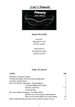
This instrument is shipped with the following items. Upon opening the shipping container, confirm that
all of the listed parts are accounted for in your shipment.
1
2
1
1
1
5
1
Fig. 1.1 Standard Contents
1
Table 1.1 Standard Contents
1
Check
1
Description
Part No.
Qty.
1
Spectrophotometer
206-25201-91
1
2
AC Power Cable
071-60816-12
1
1
3
UV-1800 Instruction Manual-System User's
Guide (This manual)
206-97040
1
1
4
UV-1800 Instruction Manual-Operation
Guide
206-97042
1
5
UVProve Software (Install CD)
206-21439-91
1
6
UVProve Tutorial (Instruction Manual)
206-94459
1
7
Shimadzu User Authentication Tool
Instruction Manual
223-10410
1
1
1
1
1
1-2
UV-1800 SERIES
1.2
1.2
Components
1.2.1 UV-1800 Main Body, Front and Top Views
1
6
1
1
3
1
1
2
1
5
1
1
1
4
1
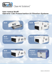
Fig. 1.2 Front and Top Views of UV-1800
1
No.
Name
1
LCD
2
Keypad
Description
This displays the operation menus and measurement results.
1
This is the input component for giving operation commands and numeric
values to the instrument, etc.
^ "1.2.5 Keypad"
1
3
Sample Compartment
Cover
Open/close this cover when setting the measured sample.
^ "1.2.4 Sample Compartment"
4
Sample Compartment
Set Screws
These are screws for fastening the sample compartment unit.
^ "4.2 Removing/Installing the Sample Compartment Unit (Standard)"
5
LED
6
Light Source
Compartment Cover
1
This lights when the power to the unit is ON.
This is the cover of the light source compartment. Open/close this cover
when replacing the light source lamp.
^ "3.4 Replacing the Light Source"
UV-1800 SERIES
1-3
1.2 Components
1.2.2 UV-1800 Main Body, Left Side View
1
1
1
1
100-120, 220-240V~
50-60HZ 140VA
AC IN
1
2
1
4
1
SIPPER
3
100-120, 220-240V~
50-60HZ 140VA
AC IN
1
SIPPER
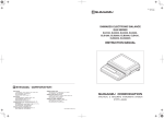
Fig. 1.3 Left Side View of UV-1800
1
1
No.
Name
Description
1
USB Connector
You can use these connecters for any of printer, or USB memory stick.
You can also connect special accessories described below. In such
cases, however, it is necessary to purchase separately and connect the
designated USB conversion adaptor to each accessory.
• 6-cell electronic temperature control cell positioner CPS-240A/B
Ö USB adaptor for CPS (P/N 206-25234-91)
• Auto sample changer ASC-5
Ö USB adaptor for ASC (P/N 206-25235-91)
For installation and connection procedures, refer to the instruction
manual of each accessory.
2
USB Connector (for PC)
This is the connector for connecting PC during external control
operation.
^ Operation Guide, "17.1 Connecting to a PC"
3
Optional Unit Connector
This is the connector to connect the "Sipper 160" or "Syringe sipper"
(special accessories).
For installation and connection procedures, refer to the instruction
manual of each accessory.
4
AC Power Connector
1
1
1
1
1-4
UV-1800 SERIES
Connect the enclosed AC power cable to the supply power from an AC
electrical outlet.
^ "2.2 Connecting Power"
1.2 Components
1.2.3 UV-1800 Main Body, Right Side View
1
1
1
1
1
1
1
1
2
Fig. 1.4 Right Side View of UV-1800
No.
Name
1
USB Connector
2
Power Switch
1
1
Description
Plug in the USB memory to this connector.
1
Use this switch to turn ON/OFF the instrument. Press the "I" side on the
switch to turn ON; press the "O" side to turn OFF.
1
1
1
1
UV-1800 SERIES
1-5
1.2 Components
1.2.4 Sample Compartment
1
1
1
4
1
1
Reference side
cell holder
1
2
1
Measurement
side cell holder
1
1
3
Fig. 1.5 Sample Compartment
1
1
No.
Name
Description
1
Cell Holder
The cell holder for the rectangular 10 mm light path cells has one sample
cell holder and one reference cell holder.
^ "6.5 List of Cells"
2
Cell Holder Set Screws
The cell holder can be easily removed by loosening the cell holder set
screws.
^ "4.1 Removing/Installing the Cell Holder"
3
Sample Compartment
Front Cover
When using a flow cell, etc., holes are needed to pass tubing, etc.
through. Therefore, this "Sample Compartment" can be removed and
exchanged with different types of front panels.
^ "4.3 Removing/Installing the Sample Compartment Front Cover"
4
Multi-cell Holder Drive
Connector
This is the connector for connecting the control cables for multi-cell
sample compartment and 8/16-cell micro multi cell holder (MMC-1600)
(special accessories).
1
1
1
1-6
UV-1800 SERIES
1.2 Components
1.2.5 Keypad
1
6
1
7
5
1
8
1
1
9
a
0
1
1
Fig. 1.6 Keypad
No.
Name
1
Description
This is the key for starting and stopping measurement once the
parameter setting has been completed.
1
1
When you press this key, the absorbance (transmittance) at the current
wavelength will automatically be set to 0Abs (100 %T). Make sure that
prior to sample measurement a blank cuvette is placed in both sample
and reference sides.
1
3
This is the key that is used to change the current wavelength.
1
4
When you enter a value, press this key after the value to set the entering
value.
1
2
Use these keys to move the cursor on the screen upward/downward, or
left/right. The left cursor key can also be used to enter a negative (–)
value when entering numeric values.
1
6
These are the keys corresponding to the functions that are displayed at
the bottom of the screen.
1
7
Use this key to display to the previous screen.
8
Use this key to adjust the screen contrast. Using cursor keys
while holding down this key changes the contrast.
9
Use this key to output a hard copy of the screen.
0
Use these keys to enter numeric values.
5
a
Use this key to clear a numeric value entry error. When you press this
key, the numeric value which has been entered will be cleared and then
you may reenter the appropriate value.
UV-1800 SERIES
1-7
1.2 Components
1.2.6 Light Source Compartment
1
1
1
3
1
1
1
1
2
1
1
Fig. 1.7 Light Source Compartment
1
1
No.
Name
Description
1
Deuterium Lamp (D2
Lamp)
This is the ultraviolet range (190 nm to light source switch wavelength*)
light source. For the D2 lamp replacement procedure, refer to "3.4
Replacing the Light Source".
2
Tungsten Halogen
Lamp (WI Lamp)
This is the visible & near infrared range (light source switch wavelength*
to 1100 nm) light source. For the WI lamp replacement procedure, refer
to "3.4 Replacing the Light Source".
3
3rd light source (on
installation site)
You can install a light source other than the standard lamps or the
introduction unit of external light source.
1
1
* Light source switch wavelength
The light source switch can be set anywhere in the range from 295 nm to 364 nm in 0.1 nm increments.
For details, refer to the Operation Guide, "12.2 Explanation for Setting Instrument Parameters", [4. Light
Source Switching Wavelength].
1
1-8
UV-1800 SERIES
2
2 Installation
2
2
Chapter 2 Installation
2
2
2
2
CONTENTS
2.1
2.2
2.3
2.4
2.5
2.6
2.7
2
Installation Site .................................................................................................................................. 2-2
Connecting Power ............................................................................................................................. 2-4
Checking the Light Source Lamp (D2) .............................................................................................. 2-7
Operation Precautions ....................................................................................................................... 2-8
Turning ON the Power and Initialization ............................................................................................ 2-9
Instrument Baseline Correction ....................................................................................................... 2-13
Performance Check after Installation .............................................................................................. 2-15
2
2
2
2
2
2
UV-1800 SERIES
2-1
2.1
2.1
Installation Site
2.1.1 Installation Requirements and Preparation
2
To use the UV-1800 properly and safely, install the instrument in an appropriate location that meets
the following requirements.
2
WARNING
When using flammable and toxic samples, be sure to install ventilation equipment at
installation site.
2
2
2
CAUTION
2
• DO NOT install the UV-1800 in an environment filled with dust or corrosive gas.
These conditions will adversely affect the durability and performance of the UV-1800.
2
• DO NOT install the UV-1800 near an instrument that produces strong magnetic fields.
2
Magnetic fields may adversely affect the accurate performance of the instrument.
Filters may be added to the power supply lines to reduce any electrical noise.
2
• To ensure instrument performance, the installation site should meet the following
requirements.
2
• The ambient temperature must be between 15 °C and 35 °C with minimal temperature
variations.
• Air currents from air conditioners and heating systems must be avoided.
• Exposure to direct sunlight must be avoided.
• The site must be free from vibration.
• Humidity must remain between 35 % and 80 %. No condensation.
(Humidity must be maintained at under 70 % at ambient temperatures over 30 °C.)
2
2
2
2-2
UV-1800 SERIES
2.1 Installation Site
2.1.2 Installation Space
2
2
CAUTION
• The weight of the UV-1800 is 15 kg. When selecting the installation location, take into
account the total weight of the UV-1800 and other devices.
Use a desk or stand for installation that can sufficiently support the total instrument
weight, having a flat and stable surface with at least 600 mm depth. If these
requirements are not satisfied, the instrument may tip over or fall down, causing an
accident.
2
2
• Ensure that there is at least 100 mm of clearance between the left side of the UV-1800
and the wall.
2
The power supply unit and the light source unit cooling fan are located on the left side
of the instrument. If location specifications are not met, the air cooling system with fan
may work improperly, overheating the instrument and deteriorating its performance.
2
2
The dimensions of the UV-1800 are as given in the figure below.
2
2
2
490 mm
2
2
2
450 mm
2
270 mm
Fig. 2.1
UV-1800 SERIES
2-3
2.2
2.2
Connecting Power
2.2.1 Verifying Power Supply Voltage
2
2
WARNING
The power supply voltage is indicated on the power supply connector on the side of the
instrument. Be sure to connect the power supply that meets the indicated
specifications.
Operating the UV-1800 at supply voltages other than the specified could cause fire,
electric shock, and instrument malfunction.
2
2
2
2
2
2
Power voltage
indication
100-120, 220-240V~
50-60HZ 140VA
AC IN
2
SIPPER
2
Fig. 2.2
2
The following table shows the power supply voltage, power consumption, and frequency of the UV-1800.
2
Power Supply Voltage
(Indication on product nameplate)
Power Consumption
Frequency
100 V - 120 V AC, 220 V - 240 V AC
(100-120, 220-240 V -)
140 VA
50 - 60 Hz
Verify that the outlet to be used has a sufficient power capacity. Insufficient power capacity may cause blackouts
and voltage drops, affecting other instruments that use the same power supply.
The range of the allowable voltage fluctuation is within ±10 %. If the fluctuation exceeds 10 %, be sure to use a
voltage stabilizer.
2
2-4
UV-1800 SERIES
2.2 Connecting Power
2.2.2 Connecting to the Power Outlet
2
2
WARNING
Handle the power supply cable carefully.
Follow the warnings below to avoid cable
damage and the consequent risk of fire,
electric shock, and instrument malfunction.
2
• Do not place heavy objects on the power supply
cable.
• Keep thermal appliances away from the power
supply cable.
• Do not modify the power supply cable.
• Do not forcefully bend or stretch the power supply
cable.
• Hold the plug when inserting in and removing the
cable from the power outlet.
2
2
2
Should the power supply cable become
damaged, contact your Shimadzu
representative.
2
2
2
CAUTION
2
Verify that the power switch of the UV-1800 is
OFF (i.e., "O" is pressed in) before connecting
the electric plug to the outlet.
2
2
2
1
Insert the connector of the power supply cable (accessory) into the power supply connector (Fig.
1.3) on the left side of the UV-1800.
2
Insert the electric plug of the power supply cable into the power outlet.
UV-1800 SERIES
2
2-5
2.2 Connecting Power
2.2.3 Grounding
2
2
WARNING
Ground the instrument to prevent electric shock and provide reliable performance of the
UV-1800.
2
The power supply cable supplied with the UV-1800 consists of three wires including a ground wire. When
installing the instrument, be sure to insert the cable into the three-wire system outlet.
2
2
2
2
2
2
2
2
2
2
2-6
UV-1800 SERIES
2.3
2.3
Checking the Light Source Lamp (D2)
2
WARNING
2
• Before opening the light source compartment cover, turn OFF the instrument power
switch and remove the electric plug from the outlet. Failure to do so may result in fire,
electric shock, and instrument malfunction. DO NOT turn ON the instrument power
while the light source compartment is visually exposed. Ultraviolet light may be
generated, a serious health hazard.
2
• If the UV-1800 has been operating before opening the cover, turn OFF the instrument
and let it stand until the lamp cools down sufficiently. Touching the lamp when it is still
hot will burn you.
2
2
CAUTION
2
• When removing and installing the light source compartment cover, avoid hitting the
protrusion on the top of the D2 (deuterium) lamp (Fig. 3.8) against the back of the
cover. Doing so may cause a vacuum leak in the lamp tube.
2
• Be sure to wear gloves when handling the light source so as not to leave fingerprints on
the glass part. A fingerprint will burn onto the bulb when the light source gets hot, and
light transmission will deteriorate.
2
2
• Be careful not to break the lamp.
2
According to the procedure described below, check to be sure that the light source D2 (deuterium) lamp did not
become dislodged from the designated position during transportation.
For details on the components on the light source compartment, and the procedure to remove the cover, refer to
"3.4 Replacing the Light Source".
1
2
2
2
Remove the light source compartment cover.
Check to be sure that the D2 lamp is seated well in
the socket with no gap.
2
D2 lamp
Socket
If the lamp is mounted at an angle or there is any
gap, reinstall the lamp so that there is no gap in
between.
3
2
Mounted to the socket with no gap.
Reinstall the light source compartment cover.
Mounted at an angle
There is a gap
Fig. 2.3 Checking D2 lamp installation
UV-1800 SERIES
2-7
2.4
2.4
Operation Precautions
Precautions Before Operation
2
2
CAUTION
• Before turning ON the power switch, check to be sure that nothing is placed in the
sample compartment and cell holder.
If the power is turned ON when a sample cell is mounted to the UV-1800, the light
source energy check and wavelength check may be judged as "NG" since the light
beam is obstructed.
When this occurs, first turn OFF the power switch, remove the cell, and then turn ON
the power switch again.
2
2
2
• If "Sipper 160" (special accessory) is mounted, turn ON the power switch with the flow
cell filled with distilled water.
2
If the sample remains halfway within the cell, the light source energy check and
wavelength check may be judged as "NG" since the beam is refracted or scattered on
the remaining sample.
If this occurs, turn OFF the power switch and turn it ON again while pressing down the
sipper 160 suction lever. After the pump of the sipper 160 starts rotating, suction the
distilled water from the sample suction port. When the distilled water starts being
drained, release the lever and finish the suction operation.
2
2
2
Precautions During Operation
2
CAUTION
2
• Keep the sample compartment cover closed during measurement or 100 %T (0 Abs)
correction. Any outside light detected on the spectrometer may interfere with accurate
measurement and correction.
2
NOTE
100 %T (0 Abs) is the function to correct the current photometric value to 100 %T for transmittance
measurement, and 0 Abs for absorbance measurement. Performing this correction only for the specified
wavelength is called "Auto-zero", and performing within the specified wavelength range is "Baseline
correction".
2
2-8
UV-1800 SERIES
2.5
2.5
Turning ON the Power and Initialization
2.5.1 Power ON/OFF
2
2
2
2
Power switch
2
Fig. 2.4 UV-1800 Power Switch
Turning ON the Power
2
1
2
Press "I" on the power switch (Fig. 2.4) to turn ON
the power.
2
2
The items to be initialized appear on the screen, and
start being initialized or checked sequentially.
^ "2.5.2 Initialization Operation"
2
2
2
2
3
When all initialization items are judged "OK", the
Mode menu screen appears.
2
2
NOTE
If the security function is ON, the Login screen is
displayed prior to the Mode menu screen.
^ Operation Guide, "1.3 Login Screen"
UV-1800 SERIES
2-9
2.5 Turning ON the Power and Initialization
2
Turning OFF the Power
2
1
Press "O" on the power switch to turn OFF the
power.
2.5.2 Initialization Operation
When the instrument power is turned ON, the spectrometer executes various initializations and
checks for the items shown in Fig. 2.5. The time required for this initialization is approximately four
minutes.
2
2
Light Source Lamp Icon
Indicates the illumination status of
the light source lamp.
"W" and "D" stand for the halogen
lamp and deuterium lamp,
respectively. This icon is displayed
when the lamp is ON, and not
displayed when it is OFF. A blinking
icon indicates that the lamp is OFF
with some errors.
2
2
2
2
2
Fig. 2.5 Initialization screen
2
2
2
2
2-10
UV-1800 SERIES
2.5 Turning ON the Power and Initialization
Table 2.1 Initialization items
Initialization items
2
Description
2
LSI Initialize
Initializes each I/O device.
ROM Check
Checks program ROM.
RAM Check
Checks memory elements (RAM).
Filter Initialize
Detects the reference position of the stray light filter.
Lamp Motor Initialize
Detects the reference position of the motor that drives the light source
switching mirror.
WL Motor Initialize
Detects the mechanical wavelength origin position.
2
WI Lamp Energy
Checks whether or not the WI (halogen) lamp light energy is at a sufficient
level.
2
2
WL Origin search
Checks 0-order light which is the optical origin.
D2 Lamp Energy
Checks whether or not the D2 lamp (deuterium) lamp light energy is at a
sufficient level.
2
WL Check
Checks wavelength by detecting the emission line at 656.1 nm using the
D2 lamp.
2
Each item is initialized in order, and if the initialization of the item is properly completed, "OK" is displayed next
to the item. If any abnormality is detected, however, "NG" is displayed and the initialization process is
terminated. In such a case, note the item for which "NG" is displayed, and turn OFF the instrument. To learn the
check points when an error occurred, refer to "5.1 Errors during Initialization".
2
2
2
2
2
2
2
UV-1800 SERIES
2-11
2.5 Turning ON the Power and Initialization
2.5.3 Switching System Language
2
You can arbitrarily change the UV-1800 system language.
If Japanese language instruction manuals are necessary, please contact your Shimadzu
representative and purchase them separately.
2
• UV-1800series System Use's Guide....................... P/N 206-97039
• UV-1800series Operation Guide............................. P/N 206-97041
Switching Procedure (English to Japanese)
2
1
2
2
2
2
Turn ON the UV-1800 by pressing the "I" side of the
power switch (Fig. 2.4) while holding down the
key on the keypad.
The UV-1800 starts up in Japanese mode, and the
initialization operation begins.
^ "2.5 Turning ON the Power and Initialization"
2
2
2
Fig. 2.6
2
NOTE
2
The language mode is switched only when turning ON the power switch with the
key
pressed. When not intending to change the language mode, turn ON the power switch as usual
without holding down the
key.
2
2
2-12
UV-1800 SERIES
2.6
2.6
Instrument Baseline Correction
After installing the UV-1800, perform the instrument baseline correction.
The UV-1800 has the following two types of baseline correction:
1
2
2
Instrument Baseline Correction
This corrects the optical balance of the spectrometer itself. The baseline is corrected with a
shorter interval within the entire wavelength range (190 nm - 1100 nm), and the correction data is
stored.
NOTE
2
If the instrument baseline correction is interrupted, the stored data is not overwritten.
2
2
Baseline Correction
This corrects the baseline within the specified wavelength range to 100 %T (0 Abs). This
correction is completed quickly since it is executed within a relatively wide interval.
2
The UV-1800 uses the correction data obtained from 1 when performing 2. Therefore, the steps and
shock noises can be removed in a short time. Usually they can be removed only when corrections are
performed with the same interval as that used when the measurement data is obtained.
2
The procedure to perform "instrument baseline correction" is given below.
It takes approximately 17 minutes to complete the correction. Other UV-1800 operations are not
available during that period.
2
2
1
Verify that nothing is set on the cell holder in the sample compartment, and close the sample
compartment cover.
2
Select the
screen (Fig. 2.7).
2
[Mainte.] key in the Mode menu
2
2
2
2
Fig. 2.7
3
2
Select
[Instrument Baseline Correction] in
the Maintenance screen (Fig. 2.8).
Fig. 2.8
UV-1800 SERIES
2-13
2.6 Instrument Baseline Correction
4
2
Select [Yes] using the
keys, and
press the
key.
The instrument baseline correction is started.
2
Fig. 2.9
5
2
During the correction process, a message will be
displayed at the bottome of the screen.
To terminate the instrument baseline correction,
press the
key.
Fig. 2.10
2
2
2
2
2
2
2
2
2
2
2-14
UV-1800 SERIES
2.7
2.7
Performance Check after Installation
Once the installation is complete, validate the performance for the following items:
• Noise level
• Baseline flatness
• Wavelength accuracy
2
2
Use the instrument validation function in order to check the performance of the UV-1800. For details
on how to use the function, refer to the Operation Guide, "16. Instrument Validation Function".
2.7.1 Parameter Settings
2
Set validation parameters in the Parameter Input screen for each item as follows:
Noise level
2
Perform the validation using the parameters below.
Wavelength
: 700 nm
Tolerance
P-P : 0.30 mAbs or less
RMS : 0.05 mAbs or less
2
2
2
2
Fig. 2.11 Validation parameters for noise level
Baseline flatness
2
Perform the validation using the parameters below.
2
Scan range: 1100 - 200 nm
Tolerance : ±0.6 mAbs
2
2
2
Fig. 2.12 Validation parameters for baseline
flatness
Wavelength accuracy (D2 emission line)
2
Perform the validation using the parameters below.
Wavelength: 656.1 nm, 486.0 nm
Tolerance
656.1 nm: ±0.10 nm
486.0 nm: ±0.30 nm
Fig. 2.13 Validation parameters for
wavelength accuracy (D2 emission line)
UV-1800 SERIES
2-15
2.7 Performance Check after Installation
2.7.2 Performing Validation
2
Connect the printer to the UV-1800, and start the validation by the following procedure:
2
1
Press the
[Settings] key in the Parameter
Input screen for the instrument validation.
2
2
2
Fig. 2.14
2
2
2
In the Settings screen, set [1.Auto Print] and [Print
Init. status] to [ON].
3
Press the
key to return to the Parameter
Input screen for the instrument validation.
2
2
2
Fig. 2.15
2
4
In the screen, press the
validation.
2
5
The check result is printed out for each validation
item when the validation is complete.
6
Check the performance of each item by referring to
the printed result.
key to start the
2
Fig. 2.16
2-16
UV-1800 SERIES
3
3 Maintenance & Inspection
3
3
Chapter 3 Maintenance &
Inspection
3
3
3
CONTENTS
3.1
3.2
3.3
3.4
3.5
3
Inspection and Maintenance.............................................................................................................. 3-2
Inspecting the Sample Compartment ................................................................................................ 3-3
Checking and Resetting the Lamp Usage Time ................................................................................ 3-4
Replacing the Light Source ............................................................................................................... 3-7
Cleaning the Exterior ....................................................................................................................... 3-15
3
3
3
3
3
3
UV-1800 SERIES
3-1
3.1
3.1
Inspection and Maintenance
To use the UV-1800 safely, be sure to perform inspection and maintenance on the instrument.
3
WARNING
3
Unless otherwise specified, be sure to turn OFF the UV-1800 and remove the electric
plug from the outlet before performing inspection and maintenance. Failure to do so
may result in fire, electric shock, and instrument malfunction.
3
3
CAUTION
3
• When replacing parts, always use the parts specified in "1.1 UV-1800 Configuration" or
"6.2 Maintenance Parts". Using parts other than those specified may damage the parts,
causing injuries or system malfunction.
3
• DO NOT remove the cover of the UV-1800. Ignoring this may cause injuries or system
malfunction.
3
For internal repair of the UV-1800, contact your Shimadzu representative.
3
3.1.1 List of Periodic Inspection & Maintenance Items
3
Inspection and maintenance
item
3
1 year
2 years
3 years
Reference
Sample compartment
inspection
"3.2 Inspecting the
Sample
Compartment"
Lamp usage time check
"3.3 Checking and
Resetting the Lamp
Usage Time"
WI (halogen) lamp
replacement
"3.4 Replacing the
Light Source"
D2 (deuterium) lamp
replacement
"3.4 Replacing the
Light Source"
3
3
3-2
Everyday
UV-1800 SERIES
3.2
3.2
Inspecting the Sample Compartment
CAUTION
3
DO NOT spill water or organic solvent on the UV-1800. Doing so may result in electrical
failure or instrument malfunction.
3
3
When analyzing liquid sample, check that no solution sample is spilled on the sample compartment
before and after measurement. Should you spill any liquid sample, wipe it up immediately.
NOTE
If spilled sample is left in the sample compartment for a while, it evaporates and fills the
compartment, corroding the internal components and interfering with correct measurement results.
3
If solution sample is spilled on the sample compartment bottom, wipe up the spilled solution after
removing the sample compartment unit. For the procedure to remove/install the sample compartment
unit, refer to "4.2 Removing/Installing the Sample Compartment Unit (Standard)".
3
3
3
3
3
3
3
3
3
UV-1800 SERIES
3-3
3.3
3.3
Checking and Resetting the Lamp Usage Time
The UV-1800 has a function to record and display the accumulated usage time of the WI (halogen)
and D2 (deuterium) lamps used for the light source.
Even though the accumulated usage time is saved to the instrument after the power is turned OFF, the
data will be cleared if any electrical problem occurs. Therefore, if you wish to use the usage time data
through this function as a reference for lamp replacement, write down the usage time on the
inspection record periodically. For the service life of each lamp, refer to "3.4.1 Light Source
Specifications".
3
3
3.3.1 Checking Procedure
3
1
Press the
screen.
[Mainte.] key in the Mode menu
3
3
3
Fig. 3.1
3
2
3
3
3
The Maintenance screen (Fig. 3.2) appears and the
accumulated usage time of the light source lamps
are displayed.
Press the
screen (Fig. 3.1).
key to return to the Mode menu
3
3
Fig. 3.2
3
3-4
UV-1800 SERIES
3.3 Checking and Resetting the Lamp Usage Time
3.3.2 Resetting Procedure
3
After replacing the light source lamp, reset the data of accumulated usage time by the following
procedure.
For the light source replacement, refer to "3.4.2 Lamp Replacement Procedure".
The procedure for resetting the lamp usage time is given below, using the D2 lamp as an example.
1
Press the
screen (Fig. 3.3).
3
[Maint.] key in the Mode menu
3
3
3
Fig. 3.3
2
Press the
[3. Reset lamp usage time] key
in the Maintenance screen (Fig. 3.4).
3
3
3
3
Fig. 3.4
3
The window for selecting the lamp whose usage is to
be reset appears.
Use the
keys to move the cursor
to [D2 lamp] (Fig. 3.5), and press the
key.
3
3
Cursor
3
Fig. 3.5
UV-1800 SERIES
3
3-5
3.3 Checking and Resetting the Lamp Usage Time
4
Use the
press the
keys to select [Yes], and
key.
The lamp usage time will be reset.
3
3
3
Fig. 3.6
5
You will return to the [Maintenance] screen (Fig. 3.7).
Verify that [D2 lamp usage time] is reset to "0 hours".
6
Press the
screen (Fig. 3.3).
3
3
key to return to the Mode menu
3
3
Fig. 3.7
3
3
3
3
3
3-6
UV-1800 SERIES
3.4
3.4
Replacing the Light Source
3.4.1 Light Source Specifications
The UV-1800 uses two types of light source lamps: D2 (deuterium) lamp and WI (halogen) lamp. The
D2 lamp and WI lamp are used for ultraviolet region (190 nm - light source switching wavelength*1)
and visible/near-infrared region (light source switching wavelength*1 - 1100 nm), respectively.
The closer the lamp service life comes to its end, the smaller the light intensity of each lamp, and the
greater the noise in photometric data.
Replace the light source lamp by referring to the "Rating life*2" described in the table below.
3
3
*1 The light source switching wavelength can be arbitrarily specified within the range between 295 nm
and 364 nm in increments of 0.1 nm. For details, refer to the Operation Guide, "14.1 Setting
Instrument Parameters", [4. Light source].
3
*2 The rating life below has been determined based on "average life" of a large number of lamps by
the lamp manufacturer. Please note that some lamps may burn out before they reach the end of
their rating lives.
3
Table 3.1
Name
Part No.
Type
3
Rating Life
1 WI (halogen) lamp
062-65005
NA55917
Appox. 2000 hours
2 D2 (deuterium lamp)
062-65055-05
L6380
Appox. 2000 hours
3
3
Protrusion on top
3
3
3
Beam port
3
Beam port
3
1 WI (halogen) lamp
2 D2 (deuterium) lamp
3
Fig. 3.8 Light source appearances
UV-1800 SERIES
3-7
3.4 Replacing the Light Source
3.4.2 Lamp Replacement Procedure
3
WARNING
3
• Before replacing the lamp, turn OFF the instrument power switch and remove the
electric plug from the outlet. Failure to do so may result in fire, electric shock, and
instrument malfunction. DO NOT turn ON the instrument power while the light source
compartment is visually exposed. Ultraviolet light may be generated, a serious health
hazard.
3
• Before replacing the lamp, turn OFF the instrument and let it stand until the lamp cools
down sufficiently. Touching the lamp when it is still hot will burn you.
3
3
CAUTION
3
• When removing and installing the light source compartment cover, avoid hitting the
protrusion on the top of the D2 (deuterium) lamp (Fig. 3.8) against the back of the
cover. Doing so may cause a vacuum leak in the lamp tube.
3
• Be sure to wear gloves when handling the light source so as not to leave fingerprints on
the glass part. A fingerprint will burn onto the bulb when the light source gets hot, and
light transmission will deteriorate.
3
• Be careful not to break the lamp.
3
• When replacing the WI (halogen) lamp, your hand may contact the D2 lamp. Cover the
D2 lamp with a clean paper or cloth or remove the D2 lamp before the work.
3
• After inserting the WI lamp into the socket, DO NOT forcedly move it to right and left or
up and down. The connection part between the pin and glass may crack, which makes
it impossible for the lamp to illuminate.
3
3
3-8
UV-1800 SERIES
3.4 Replacing the Light Source
Removing the light source compartment cover
1
3
Using a Philips screwdriver, loosen the fixing screw
located on the side of the light source compartment
cover.
3
3
Fixing
screw
2
3
Lift up the side part of the cover to release the notch
from the fixing screw.
3
3
3
3
Notch (on the light
source compartment
cover)
3
3
3
Fixing screw
While sliding the light source compartment cover
and lifting it up at an angled (following the arrow
direction in Fig. 3.9), remove it from the main body.
3
3
3
Fig. 3.9 Removing the light source
compartment cover
UV-1800 SERIES
3-9
3.4 Replacing the Light Source
3
5
3
3
4
2
1
3
3
3
3
1 WI lamp
4 D2 lamp
2 WI lamp socket
5 Light source switching mechanism
3 WI lamp retainer spring
Fig. 3.10 Interior of light source compartment
3
Replacing the WI (halogen) lamp
3
When replacing the WI (halogen) lamp, your hand may contact the D2 lamp. Cover the D2 lamp with a clean
paper or cloth or remove the D2 lamp before the work. To remove the D2 lamp, refer to " Replacing the D2
lamp" in this section.
3
1
3
Remove the WI lamp retainer spring from the top of
the WI lamp.
3
3
Fig. 3.11
3-10
UV-1800 SERIES
3.4 Replacing the Light Source
2
Pull out the WI lamp from the socket.
3
3
3
Fig. 3.12
3
4
Wear gloves. Hold the new WI lamp at the top and
bottom so as not to taint its beam port.
Insert the new WI lamp into the socket. Push it
forward until the two pins of the WI lamp contact the
back of the socket and stop.
3
3
NOTE
The two pins of the WI lamp do not have polarity.
Either pin can be the upper side.
5
3
Fig. 3.13
3
Return the WI lamp retainer spring, removed in
procedure 1, to the original position.
3
3
3
3
3
Fig. 3.14
6
7
8
Reinstall the D2 lamp to the original position. Make
sure that no paper or cloth used for the work is left in
the light source compartment.
Install the light source compartment cover by the
reverse procedure of that described in " Removing
the light source compartment cover" in this section.
3
Fig. 3.15
Insert the electric plug into the outlet, and switch ON
the UV-1800. (Press the "|" side on the switch.)
UV-1800 SERIES
3-11
3.4 Replacing the Light Source
9
3
The initialization process starts. Verify that the
initialization for all items is successfully completed.
(i.e., "OK" is displayed for all items.)
the Mode menu screen is displayed, follow the
10 When
procedure in "3.3.2 Resetting Procedure" to reset
3
the WI lamp usage time.
3
Fig. 3.16
3
3
3
3
3
3
3
3
3
3-12
UV-1800 SERIES
3.4 Replacing the Light Source
Replacing the D2 lamp
1
Wear gloves. Hold the resin part of the D2 lamp, and
slowly pull it straight up.
2
Slowly extract the D2 lamp upward to remove it from
the socket.
3
3
3
3
Fig. 3.17
3
Insert the new D2 lamp into the socket. Fit the
locating lug at the bottom of the D2 lamp to the
socket notch.
Make sure that the lamp is inserted all the way.
3
3
4
Install the light source compartment cover by the
reverse procedure of that described in " Removing
the light source compartment cover" in this section.
3
3
Notch (on the socket)
3
Locating lug
3
3
Fig. 3.18
5
Insert the electric plug into the outlet, and switch ON
the UV-1800. (Press the "|" side on the switch.)
3
3
Fig. 3.19
UV-1800 SERIES
3-13
3.4 Replacing the Light Source
6
3
7
3
The initialization process starts. Verify that the
initialization for all items is successfully completed.
(i.e., "OK" is displayed for all items.)
When the Mode menu screen is displayed, follow the
procedure in "3.3.2 Resetting Procedure" to reset
the D2 lamp usage time.
3
Fig. 3.20
3
3
3
3
3
3
3
3
3
3-14
UV-1800 SERIES
3.5
3.5
Cleaning the Exterior
When the instrument case, sample compartment cover, and operation keypad get dirty or stained,
wipe them with a dry, soft cloth or tissue.
Remove more stubborn stains by the following procedure:
1
3
Dip a cloth into watered-down mild detergent and wring it well. Wipe the instrument with it.
3
2
Dip a cloth into water and wring it well. Wipe off any detergent residue on the instrument completely.
Then, wipe the moisture off with a dry cloth.
3
NOTE
DO NOT leave any spilled water on the UV-1800. DO NOT use alcohol or paint thinner solvents for
cleaning. Doing so may cause the instrument surface to rust or discolor.
3
3
3
3
3
3
3
3
3
3
UV-1800 SERIES
3-15
3.5 Cleaning the Exterior
3
3
3
3
3
3
3
This page is intentionally left blank.
3
3
3
3
3
3-16
UV-1800 SERIES
4
4 Replacing the Sample Compartment Parts
Chapter 4 Replacing the
Sample Compartment
Parts
4
4
4
4
CONTENTS
4.1
4.2
4.3
4
Removing/Installing the Cell Holder................................................................................................... 4-2
Removing/Installing the Sample Compartment Unit (Standard) ........................................................ 4-4
Removing/Installing the Sample Compartment Front Cover ............................................................. 4-7
4
4
4
4
4
4
UV-1800 SERIES
4-1
4.1
4.1
Removing/Installing the Cell Holder
To install some special accessories, such as Ultra-micro cell holder (P/N 206-14334), it is necessary
to replace the standard cell holder in the sample compartment.
In such a case, remove/install the cell holder by the following procedure:
4
Sample compartment
cover
4
Standard cell holder
Knurled screw
4
4
4
Fig. 4.1 Sample compartment (standard)
4
4.1.1 Removing the Cell Holder
4
1
2
4
Open the sample compartment cover.
Loosen the knurled screw fixing the cell holder.
Remove the cell holder.
Knurled screw
4
4
Cell holder
4
Fig. 4.2
4-2
UV-1800 SERIES
4.1 Removing/Installing the Cell Holder
4.1.2 Installing the Cell Holder
1
While aligning the locating hole on the cell holder
with the locating pin on the sample compartment
unit, place the cell holder on the sample
compartment unit.
Arrow mark
4
Knurled screw
NOTE
4
Install the cell holder so that the beam passes
through it as directed by the arrow mark.
2
Cell holder
Fix the cell holder with the knurled screw.
4
4
4
Locating pin
4
Locating hole
4
Fig. 4.3
4
4
4
4
4
UV-1800 SERIES
4-3
4.2
4.2
Removing/Installing the Sample Compartment
Unit (Standard)
To install some special accessories, such as Sipper 160 series (P/N 206-23790-91, etc.), it is
necessary to replace the standard sample compartment unit in the sample compartment. In such a
case, remove/install the standard sample compartment unit by the procedure described below. For
installing/removing those special accessories, refer to the instruction manual of each special
accessory.
4
Sample compartment
cover
4
4
Sample compartment
unit fixing screws
Fig. 4.4 Main body front view
4
4.2.1 Removing the Sample Compartment Unit
4
1
4
4
2
4
Loosen two of the sample compartment unit fixing
screws located at the bottom of the sample
compartment.
Fixing pin (on the UV-1800)
Notch (on the sample
compartment unit)
Open the sample compartment cover to remove
the sample compartment unit.
1)
4
Pull out the sample compartment in the
direction that releases the notch from the
fixing pin.
NOTE
4
DO NOT loosen the fixing pin. You can
release the notch without loosening the
fixing pin.
4
2)
Fig. 4.5
While slightly lifting up the sample
compartment unit, pull the unit out from the
fixing pin at an angle.
Fig. 4.6
4-4
UV-1800 SERIES
4.2 Removing/Installing the Sample Compartment Unit (Standard)
4.2.2 Installing the Sample Compartment Unit
4
CAUTION
Fix the sample compartment unit securely to the instrument main body using the fixing
screws (knurled screws). If the sample compartment unit is not seated properly, outside
light from the gap makes it impossible to obtain accurate measurement data.
1
4
Open the sample compartment cover and install the sample compartment unit.
1)
At an angle from above, insert the notch on
the sample compartment unit to the locating
pin at the far side of the sample
compartment.
Notch (on the sample
compartment unit)
Locating pin
(on the UV-1800)
4
4
4
4
4
Fig. 4.7
2)
4
Push the sample compartment unit forward
so that the notch is pressed into the locating
pin.
4
4
4
Fig. 4.8
UV-1800 SERIES
4
4-5
4.2 Removing/Installing the Sample Compartment Unit (Standard)
3)
4
Make sure that the sample compartment
unit front cover and the UV-1800 main body
fit together snugly.
If they don't, press the sample compartment
unit down to the sample compartment
bottom.
4
4
Fig. 4.9
4
2
4
Tighten two of the sample compartment fixing
screws (Fig. 4.4) to fix the sample compartment
unit.
4
NOTE
Align the screw holes on the sample
compartment unit with the knurled screws
by moving the unit back and forth.
4
4
3
4
Close the sample compartment cover (Fig. 4.4).
Fig. 4.10
4
4
4-6
UV-1800 SERIES
4.3
4.3
Removing/Installing the Sample Compartment
Front Cover
To install some special accessories, such as syringe sipper (P/N 206-23890-91), it is necessary to
install the designated front plate on the sample compartment.
In such a case, remove/install the sample compartment front cover by the procedure described below.
For installing/removing those special accessories, refer to the instruction manual of each special
accessory.
4
4
Fig. 4.11 Front plate for syringe sipper (switching unit)
4
4.3.1 Removing the Sample Compartment Front Cover and Installing the
Front Plate
1
Remove the sample compartment unit from the UV-1800 by the procedure described in "4.2.1
Removing the Sample Compartment Unit".
2
Turn the sample compartment unit upside down. Press the tabs (2 places) on the cover in the arrow
direction as shown in Fig. 4.12 to release them from the unit. (Fig. 4.13)
4
4
4
4
Tabs
4
4
4
Fig. 4.12 Tabs on the sample compartment front cover
4
4
Sample compartment unit
(without cover)
Sample compartment front
cover
Fig. 4.13 Sample compartment unit
UV-1800 SERIES
4-7
4.3 Removing/Installing the Sample Compartment Front Cover
4
3
Install the sample compartment unit (without cover) to the UV-1800 main body by the procedure
described in "4.2.2 Installing the Sample Compartment Unit".
4
Install the designated front plate (special accessory) to the sample compartment unit.
4
4
Fig. 4.14 Installing the front plate
4
4
5
4
4.3.2 Installing the Sample Compartment Front Cover
4
1
4
2
4
Close the sample compartment cover (Fig. 4.4).
Open the sample compartment cover and remove
the designated front plate (special accessory).
Sample compartment front plate
Remove the sample compartment unit from the UV1800 main body by the procedure described in "4.2.1
Removing the Sample Compartment Unit".
4
Fig. 4.15 Sample compartment front
plate
4
4-8
UV-1800 SERIES
4.3 Removing/Installing the Sample Compartment Front Cover
3
Fit the protruded parts on the sample compartment unit
to the corresponding protruded parts on the front cover
(2 places).
Protruded part on the front
cover
Protruded part on the
sample compartment unit
4
4
4
Fig. 4.16 Fitting the sample
compartment front cover
4
5
6
4
4
Snap the sample compartment front cover into the
sample compartment unit. Push the cover in the
arrow direction in Fig. 4.17 until it snaps.
4
Install the sample compartment unit to the UV-1800
main body by the procedure described in "4.2.2
Installing the Sample Compartment Unit".
Close the sample compartment cover (Fig. 4.4).
4
4
Fig. 4.17 Snapping the sample
compartment front cover
4
4
4
4
UV-1800 SERIES
4-9
4.3 Removing/Installing the Sample Compartment Front Cover
4
4
4
4
4
4
This page is intentionally left blank.
4
4
4
4
4
4-10
UV-1800 SERIES
5
5 Troubleshooting
Chapter 5
Troubleshooting
5
5
5
CONTENTS
5.1
5.2
5
Errors during Initialization .................................................................................................................. 5-2
Problems: Symptoms and Solutions.................................................................................................. 5-4
5
5
5
5
5
5
UV-1800 SERIES
5-1
5.1
5.1
Errors during Initialization
After the power is turned ON, the UV-1800 initializes and checks the following items listed in the table
below.
5
1
2
3
4
5
6
7
5
8
9
0
5
Fig. 5.1 Initialization screen
5
Table 5.1 Initialization items
5
Item No.
Initialization items
Description
1
LSI Initialize
Initializes each I/O device.
2
ROM Check
Checks program ROM.
3
RAM Check
Checks memory elements (RAM).
4
Filter Initialize
Detects the reference position of the stray light filter.
5
Lamp Motor Initialize
Detects the reference position of the motor that drives the light
source switching mirror.
6
WL Motor Initialize
Detects the mechanical wavelength origin position.
5
7
WI Lamp Energy
Checks whether or not the WI (halogen) lamp light energy is at a
sufficient level.
5
8
WL Origin search
Checks 0-order light which is the optical origin.
9
D2 Lamp Energy
Checks whether or not the D2 (deuterium) lamp light energy is at a
sufficient level.
0
WL Check
Checks wavelength by detecting the emission line at 656.1 nm
using the D2 lamp.
5
5
5
5
5-2
UV-1800 SERIES
5.1 Errors during Initialization
When [NG] is displayed during initialization, perform the appropriate remedial actions by referring to
the table below. If the problem is not resolved by these actions, contact your Shimadzu representative.
Item No.
Check Point
1~6
7, 8
5
Reference
Page
Remedial Action
Turn OFF the UV-1800 power switch, and turn
it ON to initialize the instrument again.
P2-9
Is there anything
obstructing the beam
in the sample
compartment cell
holder?
Turn OFF the UV-1800 power switch.
Remove the obstruction and turn ON the power
switch again.
P2-9
Is the light source
lamp icon [W]
displayed on the upper
right of the screen?
If the icon is not displayed (i.e., only frame is
displayed), it means that the WI lamp is
currently OFF.
5
P2-9
P3-7
5
5
Fig. 5.2
Turn OFF the UV-1800 power switch, and turn
it ON again. If the lamp still does not illuminate,
replace the WI lamp by the procedure
described in "3.4 Replacing the Light Source".
9, 0
Is there anything
obstructing the beam
in the sample
compartment cell
holder?
Turn OFF the UV-1800 power switch. Remove
the obstruction and turn ON the power switch
again.
Is the light source
lamp icon [D]
displayed on the upper
right of the screen?
If the icon is not displayed (i.e., only frame is
displayed), it means that the WI lamp is OFF.
5
5
P2-9
5
5
P2-9
P3-7
5
5
Fig. 5.3
5
Turn OFF the UV-1800 power switch, and turn
it ON again. If the lamp still does not illuminate,
replace the WI lamp by the procedure
described in "3.4 Replacing the Light Source".
UV-1800 SERIES
5-3
5.2
5.2
Problems: Symptoms and Solutions
Check whether the problem exhibits the following symptoms before requesting a repair.
Contact your Shimadzu representative if the error cannot be resolved through the remedial action
described below, or if the symptom is not covered in the table.
5
Typical Cause
Turning ON the power
switch does not supply
the power.
Is the AC power cable
plug connected
properly?
Connect the AC power cable plug
correctly.
Is the AC power cable
trapped underneath or
twisted?
Replace the AC power cable with the
cable of the same type if it is
damaged.
Does the supplied
power satisfy the
power supply
specification of the
UV-1800?
Use the power supply that satisfies
the instrument power supply
specification of the UV-1800.
5
5
[NG] is displayed next
to initialization items.
5
Nothing appears on
the screen.
5
Reference
Page
Symptom
——————
Is the display contrast
properly adjusted?
Remedial Action
Perform an appropriate action by
following the instruction in "5.1 Errors
during Initialization".
P2-5
P1-2
P2-5
P2-4
P5-2
Adjust the display contrast by using
the
keys while
holding down the
key on
P1-7
the keypad.
5
5
5
Numbers cannot be
entered from the
keypad.
Is an incorrect value
being entered?
Example:
, 1150 (nm)
Enter the correct value.
Photometry values are
odd.
Is the light source
lamp lit?
Check if the light source lamp icon
([W] or [D]) is displayed.
——
5
Fig. 5.4
5
When the icon is not displayed
(Only frame is displayed)
[Action]
The lamp is currently OFF.
1)Turn OFF the UV-1800 power
switch, and turn it ON again.
2)When the result of the energy
check during initialization is [NG]
(^ Fig. 4.1), replace the lamp by
the procedure in "3.4 Replacing the
Light Source".
5
5-4
UV-1800 SERIES
P2-9
P3-7
5.2 Problems: Symptoms and Solutions
Symptom
Photometry values are
odd.
Baseline curve does
not meet normal
specifications.
(^ "6.1.1 Hardware
Specifications")
Typical Cause
Is the light source
lamp lit?
Remedial Action
Reference
Page
When the icon is blinking
[Action]
The lamp is currently OFF with some
errors.
The fan is not working or the thermo
censor on the circuit board has
detected overheating.
Turn OFF the UV-1800 power switch
and contact your Shimadzu
representative.
——
Did you mistakenly
press the
key during
measurement?
Return to the blank condition
(reference condition) and press the
key again.
Is the cell being used
an appropriate one?
Do not use a glass cell in the
ultraviolet range.
Is a cell phone being
used near the
instrument?
The measured value may be
influenced depending on the types of
cell phones and the radio waves
conditions. Avoid using a cell phone
near the instrument during
measurement.
5
5
P1-7
5
——
5
——
5
5
When correcting the
baseline, did you put a
solvent with high
absorbance in the cell
holder on only one
side?
Place cells with the same solvent in
both the sample side and the
reference side and perform baseline
correction again.
Is the beam on only
one side restricted?
Set the beam conditions so that they
are identical on both the sample side
and the reference side.
——
Are you using an
optional accessory?
Some of the unit specifications may
not be met when certain optional
accessories are installed.
——
5
If none of the above
three scenarios
applies.
Correct the instrument baseline
according to "2.6 Instrument Baseline
Correction".
P2-13
5
——
5
5
UV-1800 SERIES
5
5-5
5.2 Problems: Symptoms and Solutions
5
Symptom
Neither light source
lamp lights.
"It failed in the access
to the file."
5
5
5
"Cannot load this file."
5
5
Typical Cause
Is the Cooling fan
working?
Check if air is expelled from the
exhaust port located on the left side
rear of the instrument.
If the fan has stopped, turn OFF the
UV-1800 power switch and contact
your Shimadzu representative.
Reference
Page
——
Is the USB memory or
its file system intact?
Use a normal USB memory.
Did you unplug the
USB memory during
file access?
Reconnect the USB memory and
retry accessing the file.
Is the USB memory
write-protected?
Turn OFF the USB memory write
protection function.
Is the USB memory
drive encrypted by its
security function?
Cancel the encryption of the USB
memory.
——
Has the file been
saved in the
UVProbe?
The files once saved in the UVProbe
cannot be loaded on the UV-1800.
——
Has the file been
properly saved?
The selected file may be corrupted.
In that case, the file cannot be
loaded.
5
5
5
5
5
5-6
Remedial Action
UV-1800 SERIES
——
——
——
——
6
6 Reference
Chapter 6 Reference
6
6
CONTENTS
6.1
6.2
6.3
6.4
6.5
6.6
6
Specifications .................................................................................................................................... 6-2
Maintenance Parts............................................................................................................................. 6-8
Spectrophotometer Basics ................................................................................................................ 6-9
Measurement System...................................................................................................................... 6-22
List of Cells ...................................................................................................................................... 6-25
Cleaning the Cell ............................................................................................................................. 6-28
6
6
6
6
6
6
UV-1800 SERIES
6-1
6.1
Specifications
6.1
6.1.1 Hardware Specifications
6
Measurement Wavelength Range
190~1100 nm
Spectral Band Width (Resolution)
1±0.2 nm
Wavelength Accuracy
±0.1 nm (656.1 nm D2), ±0.3 nm (All region)
Wavelength Repeatability
±0.1 nm
Wavelength Scanning Speeds
When shifting wavelength: approx. 6000 nm/min
When scanning wavelength:approx. 3000 nm/min ~ 2 nm/min
Light Source Switching
Automatic switching with wavelength range. Can be set anywhere in
range from 295 nm to 364 nm (0.1 nm units)
Stray Light
0.02 % or less (220 nm, NaI)
0.02 % or less (340 nm, NaNO2)
1 % or less (198 nm, KCl)
Photometric System
Double beam optics
Photometric Range
Absorbance: -4~4 Abs, Transmittance: 0~400 %
Photometric Accuracy
±0.002 Abs (at 0.5 Abs), ±0.004 Abs (at 1 Abs), ±0.006 Abs (at
2 Abs); Tested by using NIST930D or NIST1930, or other appropriate
standard filter.
Photometric Repeatability
0.001 Abs or less (at 0.5 Abs), 0.001 Abs or less (at 1 Abs),
0.003 Abs or less (at 2 Abs)
Noise Level
Within 0.00005 Abs (700 nm)
Baseline Flatness
±0.0006 Abs (190 nm ~ 1100 nm)
1 hour after the light source is ON.
Baseline Stability
Within 0.0003 Abs/h (700 nm)
1 hour after the light source is ON.
6
Light Source
20 W halogen lamp, Deuterium lamp
Built-in light source position automatic adjustment mechanism
6
Monochromator
Czerny-Turner spectrometer
Uses blazed holographic grating
Detector
Silicon photodiode
Sample Compartment
Interior dimensions: 110 × 250 × 115 (mm) (W × D × H)
Dimensions
450 × 490 × 270 (mm) (W × D × H)
Weight
15 kg
Operating Temperature
15 °C ~ 35 °C
Operating Humidity
30 % ~ 80 % (No condensation, 70 % or less at 30 °C or higher)
Power Supply
AC 100 V/120 V/220 V/230 V/240 V, 50/60 Hz
Power Consumption
140 VA
6
6
6
6
6
6
6
6-2
UV-1800 SERIES
6.1 Specifications
6.1.2 Software Specifications
Photometric
6
One-wavelength measurement
(1) Photometric modes: Absorbance (Abs), transmittance (%T)
(2) Simple quantification by K-factor method
(3) Save/Load table data function
Multi-wavelength measurement
(1) Photometric modes: Absorbance (Abs), transmittance (%T)
(2) Max. 8 wavelengths (Wavelength setting is possible by the unit of
0.1 nm.)
(3) Wavelength calculation function:
Calculation using data at up to 4 wavelengths is possible.
• Ratio and difference between the photometric values of
two wavelengths, three wavelength calculation
• 4 data calculation: (K1 × A1 + K2 × A2 + K3 × A3 + K4 ×
A4) × K5
• 4 data calculation: K5 × (K1 × A1 + K2 × A2)/(K3 × A3
+K4 × A4)
* An (n = 1 to 4) indicates absorbance at the measurement
wavelength of λn (n = 1 to 4)
Spectrum
6
6
6
(1) Measurement mode: Absorbance (Abs), transmittance (%T), and
energy (E)
6
(2) Scan range: 190 nm to 1100 nm
(3) Scan speeds: Fast, Medium, Fast, Medium, Slow, Very slow
6
(4) Vertical axis recording range: Abs; -4.000 to 4.000 (Min. range;
- 0.001 to 0.001)
%T, E; -400.0 to 400.0 (Min. range;
- 0.1 to 0.1)
6
(5) Scan repetitions: 1 to 99
6
(6) Recording method: Overlay/ Sequential selectable
6
(7) Reduce/Expand [zoom], Display data with cursor
(8) Save/Load data function
6
UV-1800 SERIES
6-3
6.1 Specifications
6
Quantitation
(1) Measurement method:
One-wavelength/Two-wavelength/Three-wavelength quantitation,
Quantitation by derivative (1 to 4 order) calculation
(2) Functions regarding calibration curve
Automatically calculate concentration by K-factor method
Automatically calculate concentration by one-point calibration
curve method
Multi-point calibration curve
1 to 3 order regression calibration curve
Number of standard samples (1 to 10)
Select pass-through-origin conditions
Display of calibration curve formula
Display of relative coefficient of calibration curve
(3) Measurement parameter
Quantitation by repeat measurement (1 to 10 times) and taking
the average measurement value
6
(4) Save/Load table data function
(5) Automatic data print function: Results are automatically output on
hard-copy printer for every
measurement.
6
(6) Special accessories
• Linked measurement with multi-cell, 8/16 micro-multicell
and CPS-240 is possible.
• Sipper: linked measurement with the ASC-5 is possible
6
6
Kinetics
Kinetics
(1) Measure Abs time change and calculate activity values.
6
(2) Measurement time: 1 to 9999 sec/min
6
(3) Measurement using Abs difference between two wavelengths is
possible.
6
Rate-measurement
6
(1) Measure Abs time change and calculate the change in
absorbance quautity.
(2) Measurement time: 1 to 9999 sec/min
6
(3) Determine whether the measured reaction result is progressing in
linear fashion.
6-4
UV-1800 SERIES
6.1 Specifications
Time Scan
6
(1) Measure time course change in photometric values.
(2) Measurement mode: A Absorbance (Abs), transmittance (%T),
energy (E)
(3) Measurement time: 1 to 9999 sec/min
(4) Linked measurement with multi-cell, 8/16 micro-multicell and
CPS-240 is possible.
(5) Reduce/Expand [zoom], Display data with cursor
(6) Save/Load data function
Multi-Component Analysis
(1) Up to 8 components
(2) Pure and mixed samples of each constituent component can be
used as standard samples
6
(3) Besides measurement wavelengths, standard sample data can
be filed.
(4) Quantitation can be done by calling up spectra
Bio-method
DNA quantitation
6
(1) Calculate DNA/Protein concentrations and Abs ratio.
DNA concentration =K1×A1-K2×A2
Protein concentration = K3×A2-K4×A1
6
(2) Factor/measurement wavelength can be set arbitrarily.
6
(3) Background correction can be applied.
Protein quantitation
6
(1) Quantitation method: Lowry method, BCA method, Biuret
method, CBB method (Bradford method),
UV absorption method
6
6
6
6
UV-1800 SERIES
6-5
6.1 Specifications
6
Maintenance and Inspection
Function
(1) Instrument baseline correction function
(2) Display/Reset of lamp lighting time
(3) Security setting
Faculty limitation can be set for each user account.
(4) Unit validation function
1)
Correspond to 9 items
Wavelength accuracy, wavelength repeatability, spectral
band width, stray light, photometric accuracy,
photometric repeatability, baseline flatness, baseline
stability, noise level, initialization result record
2)
Semi-automatic test:
For items requiring test jigs, test can be progressed in
the form of dialog.
3)
Full automatic test:
Test is automatically performed from measurement to
pass/fail judgment/result printing.
4)
Setting test conditions/pass fail judgment criteria
5)
Detailed printing of the test results
6)
Printing of all test result
6
6
File Management Function
6
(1) Convert spectrum and time course curve to CSV format.
(2) Copy and delete files.
6
Data Processing Function
6
6
6
6
6
6-6
UV-1800 SERIES
Following processings can be performed on curve data such as
spectrum and time course curve.
• Peak/Valley detection (both possible up to 20 pcs.)
• The four rules of arithmetic
• Derivative processing
• Smoothing processing
• Area calculation
• Point-pick processing
• Print processing (printing waveform data in text format)
6.1 Specifications
Common Function
6
(1) Selection function of the setting conditions after power is
supplied, Standby at the condition setting menu of each
measurement mode, Specifying a condition file is possible
(2) Selection function of data display digits below decimal point
Abs (3 digits) %T (1 digit) or Abs (4 digits) %T (2 digits)
(3) Number of files that can be stored (built-in memory)
Measurement conditions: Max. 24 files
Curve data
: Max. 8 files
Table data
: Max. 8 files
(4) Accumulation time set function (for fixed wavelength
measurement)
(5) External control function
UV-1800 can be controlled from PC.
This function is applied for the control with bundled UVProve
software.
6
* USB cable (that supports USB 1.1) separately required
6
6
6
6
6
6
6
6
UV-1800 SERIES
6-7
6.2
Maintenance Parts
6.2
6.2.1 Consumable Parts
6
Part Name
Part No.
Remarks
Replacement Cycle
Tungsten iodine lamp
062-65005
Light source
2 years
Deuterium lamp
062-65055-05
Light source
2 years
* Replacement cycle above is a recommended value.
6.2.2 Maintenance Parts
Part Name
6
Part No.
Remarks
Light source
switching mirror
Replacement Cycle
Mirror, R(30.60)-FR
206-25347-91
3 years
Quartz plate
206-25346-91
3 years
Lens
206-25348-91
3 years
* Replacement cycle above is a recommended value.
6
6.2.3 Repair Parts
6
Part Name
6
6
6
6
AC power cable
071-60816-12
Fuse, 218 004
072-02004-22
Battery, CR2032H 38
074-73306-08
O-ring
036-15501-21
Alternate Sample Compartment
206-60184-07
Standard cell holder
206-82009-91
Sample compartment front cover
ASSY
206-25269
Sample compartment cover
206-25269
6
6
6-8
Part No.
UV-1800 SERIES
Remarks
For 100-120 V, 220-240 V
Used for fixing the quartz plate.
6.3
Spectrophotometer Basics
6.3
6.3.1 What is Light?
6
Light is a type of electromagnetic radiation with a speed of 3.0 x 10 8 m/sec in a vacuum.
Electromagnetic radiation includes X-ray, ultraviolet ray, visible ray, infrared ray, and radio waves.
(Wavelength)
20,000
m
Long wave
2,000
m
Intermediate wave
200
m
Radio waves
50
6
m
Short wave
10
m
Ultra-short wave
1
m
6
Microwave
1 mm
Far-infrared
6
Thermal rays
25 µm
Mid-infrared
Infrared rays
6
3 µm
Near-infrared
700 nm
6
Visible rays
Visible
Measured range by
spectrophotometer
400 nm
6
Near-ultraviolet
200 nm
Far-ultraviolet
(vacuum ultraviolet)
Ultraviolet rays
50 nm
X-rays
6
5 pm
(0.05 Å)
6
γ-ray
(Note) 1 mm = 10-3 m, 1 µm =
10-6
m, 1 nm = 10-9 m, 1 pm = 10-12 m
6
Fig. 6.1 Types of electromagnetic waves
UV-1800 SERIES
6-9
6.3 Spectrophotometer Basics
Wavelength is defined as the length of a single cycle and is usually indicated by a sign called lambda,
λ.
For the range of ultraviolet ray and visible lights, a unit called nm (nanometer) is used.
6
Wavelength (λ)
Wavelength (λ)
Fig. 6.2 Wavelength
6
Wavelength 400
6
450
550
600
650
Near-infrared
Purplish red
Red
500
Orange
Yellow
Blue
6
Violet
Ultraviolet
6
Green
6
Greenish blue
Bluish green
Generally, rays of various wavelengths are mixed in the light emitted from a light source (although
some emit rays of specific wavelength such as laser light source, or others emit light of several
specific wavelengths such as mercury lamps). The light of a certain wavelength extracted selectively
by the use of a monochromator is called monochromatic light. Light that includes all the rays in the
wavelength range of visible rays is called white light.
The relation between wavelength and color is as follows:
700 (nm)
Fig. 6.3 Wavelength and color of light
6
When white light is irradiated on some substance and the substance absorbs the blue light, it appears
yellow, which is the (additive) complementary color of blue. If blue monochromatic light is irradiated on
this substance, the light is absorbed and the substance appears black, indicating that no color exists.
6
6
6
6-10
Wavelength
(nm)
Color
Complementary
color
Wavelength
(nm)
Color
Complementary
color
400 - 435
Violet
Yellow green
560 - 580
Yellow green
Violet
435 - 480
Blue
Yellow
580 - 595
Yellow
Blue
480 - 490
Greenish blue
Orange
595 - 610
Orange
Greenish blue
490 - 500
Bluish green
Red
610 - 680
Red
Bluish green
500 - 560
Green
Purplish red
680 - 700
Purplish red
Green
UV-1800 SERIES
6.3 Spectrophotometer Basics
6.3.2 Ultraviolet/Visible Spectrum
6
The energy (E) of light can be expressed as follows.
E = ch/ λ
c is the velocity of light, h is Planck's constant, and λ is wavelength.
When light is irradiated on a substance, the light of certain wavelengths is absorbed according to the
molecule structure of that substance. This happens as the result of the fact that the electrons existing
at the ground state of the molecule absorb light energy and a transition to excitation state occurs. The
amount of absorption differs depending on wavelength, and so the absorption spectrum (the curve
measuring absorption when monochromatic light is irradiated to a substance with varying
wavelengths) becomes unique to that substance. The analysis of substances based on this principle
is called absorptiometry and this method allows (1) Identification, (2) Quantitative analysis, and (3)
Analysis of electron state. Also, the excited molecule loses energy due to heat and collision with other
molecules and returns to its original ground state. This process is called "radiationless transition".
In addition, the molecule may emit the absorbed light energy as light when returning to the ground
state. Fluorescent light and phosphorescence exhibit the behavior and analysis utilizing these
phenomena is called fluorometry.
6
Excited state 2
6
Phosphorescence
Radiationless transition
Fluorescence
Light
Absorbance
Excited state 1
6
Ground state
6
Fig. 6.4 Molecule energy
6
6
6
6
6
UV-1800 SERIES
6-11
6.3 Spectrophotometer Basics
6.3.3 Bouguer-Beer's Law
6
This law, which is the basic principle of quantitative analysis, is also called Lambert-Beer's law.
Incident light Io
Sample
-kcl
concentration Transmission light I = Io x 10
c
Optical pass length I
6
Fig. 6.5 Bouguer-Beer's law
When light with the intensity of Io is irradiated on a certain substance and the light with the
intensity of I has transmitted, the following relational formula is established, where K stands for
proportional constant.
At this time, I/Io is called transmittance (T), I/Io × 100 is percent transmittance (%T) and (1/T) = log (Io/
I) is called absorbance (Abs).
T = I/Io = 10 -k•c•l
Abs = log (1/T)= log (Io/I) = k • c • l
As known from the above formula, transmittance is not proportional to the concentration of the
sample, but absorbance is proportional to the concentration of the sample (Beer's law) and is
proportional to light path length (Bouguer's law). Also, the proportional constant at the time when the
light path length is 1 cm and the concentration of object component is 1 mol/l is called molar
absorptivity and is represented by the sign of ε. This molar absorptivity becomes a value unique to the
substance under specific conditions.
To fulfil Bouguer-Beer's law, it is necessary to satisfy conditions such as being free from stray light,
emission, scattering, and reflection.
6
6
6
6
6
6
6
6
6-12
UV-1800 SERIES
6.3 Spectrophotometer Basics
6.3.4 Qualitative Analysis and Quantitative Analysis
6
To analyze what a substance is and what substances it consists of is called qualitative analysis, while
analysis of the amount of these substances is called quantitative analysis.
Spectrum and Chemical Structure (Qualitative Analysis)
The absorbance of ultraviolet/visible light is determined by chromophore (functional group that
absorbs light such as C = C, C = O, N = N, and N = O, having multiplet bonding) and auxochrome
(functional group that bonds with chromophore and changes its absorbance position and intensity
such as - OH, -NH2, and -SH, having non-bonding electron pair), and so is related to the chemical
structure. In this case, absorbance may change depending on introduction of substitution group and
types of solvent. Movement of the absorbance wavelength to a longer wavelength is called
"bathochromic movement", and its movement to a shorter wavelength is called "hypsochromic
movement". Also, an increase of absorbance is called the "hyperchromic effect" and a decrease is
called the "hypochromic effect".
6
Colorimetric Analysis (Quantitative Analysis)
Analysis to perform quantitative analysis by comparing the color darkness of a substance is called
colorimetric analysis. When the substance is transparent, if absorbance exists in the invisible
ultraviolet/near infrared area, it is measured. The latter is broadly included in colorimetric analysis.
6
6
6
6
6
6
6
6
UV-1800 SERIES
6-13
6.3 Spectrophotometer Basics
6.3.5 Calibration Curve
6
The quantitative method to measure the concentration of a sample with unknown concentration from
the absorption of a sample with known concentration is provided in two methods: (1) Calibration curve
method and (2) Standard additive method.
1 Calibration curve method
2 Standard additive method
6
Absorbance
Absorbance
Absorbance of unknown
sample
Concentration of
unknown sample
Concentration of
unknown sample
Standard sample concentration
6
Standard sample concentration
Fig. 6.6 Calibration curve
In the calibration curve method, standard samples are operated according to an established method
and then measured for absorbance. A calibration curve is prepared by using the absorbance obtained
here in the vertical axis and the standard sample in the horizontal axis. There are times when the
calibration curve does not make a straight line such as when the solution to be measured is a
suspension. Although the calibration curve is sure to pass the origin when a blank solution is used, if it
is not used, the curve may not pass the origin. Next, the concentration of the object components in the
unknown sample is obtained using this calibration curve.
In the standard additive method, standard sample is added by stages to four or more samples of
measurement sample solution of the same concentration. Similarly to the calibration curve method, a
relation curve between added value and absorbance is prepared. The concentration of the object
component in the unknown sample is obtained from the point where the related curve crosses the
vertical axis. This method is applied only when the related curve is straight as far as to the low
concentration range.
Generally, extra-large absorbance wavelength is used as measurement wavelength for quantitative
analysis.
6
6
6
6
6
6
6
6-14
UV-1800 SERIES
6.3 Spectrophotometer Basics
6.3.6 Solvent Selection
6
Generally when a sample is analyzed, it is measured as a solution. Accordingly, the type and the
concentration of the solvent must be adequate. A solvent that dissolves the sample well and that is
free from mutual action, has small absorbance in measurement wavelength range and has small
volatility is desired. A cell with a lid is necessary for volatile solvent.
As a solvent, water is excellent for measuring absorbance in visible/ultraviolet range, as it has no
absorbance itself. On the other hand, many of the normally used organic solvents are transparent to
the human eye, so it can be mistakenly believed that absorbance does not exist in ultra-violet range
either. The solvents and their available operating wavelength ranges are as follows:
200
250
300
350
400
450 (nm)
Water
6
Methanol
Ethanol
Isopropanol
Methylcyclohexan
6
Cyclohexan
Acetnitrile
6
Hexane
Dioxane
Glycerin
6
n-pentane
Dichloromethane
6
Chloroform
Metylacetate
6
Metyl formic acid
Carbon tetrachloride
6
Dimethyl sulfoxide
Benzene
6
Xylene
Toluene
6
Ethylene tetrachloride
Acetone
Bromoform
Nitro methane
Carbon disulfide
200
250
300
350
400
450 (nm)
Fig. 6.7 Wavelength range for solvent to be used (using a 10 mm cell)
UV-1800 SERIES
6-15
6.3 Spectrophotometer Basics
6.3.7 Calibration Curve Curvature
6
A calibration curve is generally straight. However, it may bend due to various reasons. The probable
causes are 1 drift of measurement circuit, 2 fluorescent sample, 3 stray light, 4 broad band width,
and 5 measurement at the spectrum shoulder.
1
As a spectrophotometer has some drift immediately after power is supplied to it, it should be
allowed to warm up for 30 min. to one hour. Also, drift may be observed over a long period of
time, so it is important to check the wavelength accuracy and measurement accuracy periodically
using a filter etc.
2
When a sample emits fluorescent light and if that light enters the detector, the absorbance may
appear low and the amount of fluorescent light increases as sample concentration becomes
higher. As a result, the calibration curve may be bent toward the lower side. If this occurs, it is
necessary to reduce the influence of fluorescent light as much as possible by increasing the
distance between the sample and the detector or by inserting a mask between the sample and
the detector.
3
Stray light is the total of the light of the wavelength deviated from a certain spectrum width having
the set wavelength of the monochromator placed in the center and the light emitted from
monochromator, but does not transmit the sample and pass the side of the sample. For example,
with 0.1% of stray light included in the monochromatic light, when a sample with the wavelength
of λ o and absorbance of 2 (transmittance 1%) is measured, because 0.1% stray light is added in
addition to 1% of the light with the wavelength of λ o, the transmitted light will have 1.1% of
transmittance (absorbance 1.959), causing 2% error. As known from this, the higher the sample
absorbance is, the larger the error due to stray light becomes. To reduce stray light, it is generally
effective to form a double-monochromator by connecting two monochromators. Although it is
expensive due to the complex mechanism, the amount of stray light is reduced from one-fiftieth
(1/50) to one-one thousandth (1/1000) of that of normal single monochromator.
6
6
6
6
6
Table 6.1 Absorbance error due to stray light
6
6
6
6
Stray
light
(%)
0.8
1.0
1.2
1.5
1.8
2.0
2.5
3.0
4.0
1
0.0222
0.0370
0.0595
0.1150
0.2081
0.2967
0.6150
1.0370
2.0000
0.5
0.0133
0.0190
0.0309
0.0615
0.1169
0.1739
0.4096
0.7759
1.7059
0.2
0.0045
0.0077
0.0126
0.0257
0.0507
0.0783
0.2119
0.4762
1.3213
0.1
0.0022
0.0038
0.0063
0.0130
0.0261
0.0409
0.1188
0.3005
1.0409
0.05
0.0011
0.0019
0.0032
0.0065
0.0132
0.0209
0.0635
0.1758
0.7799
0.02
0.0004
0.0007
0.0012
0.0026
0.0053
0.0085
0.0365
0.0790
0.4770
0.01
0.0002
0.0003
0.0006
0.0013
0.0026
0.0042
0.0134
0.0413
0.3009
0.005
0.0001
0.0001
0.0003
0.0006
0.0013
0.0021
0.0067
0.0211
0.1791
0.002
0.0000
0.0000
0.0001
0.0003
0.0005
0.0008
0.0027
0.0085
0.0791
0.001
0.0000
0.0000
0.0000
0.0001
0.0002
0.0004
0.0013
0.0043
0.0413
0.0001
0.0000
0.0000
0.0000
0.0000
0.0000
0.0000
0.0001
0.0004
0.0043
Absorbance
(Test and Engineering Vol.9 No.9,702,1981)
6-16
UV-1800 SERIES
6.3 Spectrophotometer Basics
4
A halogen lamp or deuterium lamp are used as the light source of a spectrophotometer.
Because these lamps emit a continuous spectrum, taking out 500 nm monochromatic light from
the monochromator does not mean that only the light of 500 nm is taken out, but the light in a
wavelength range having a certain width is taken out.
6
Energy of light
1/2
Band width
6
Wavelength width to be taken out
Band width
1
Area
1
Total amount of energy of light 1
1/2
1/4
1/4
1/4
1/16
1/16
6
Fig. 6.8 Band width and energy of light
6
Because the absorption coefficient of a substance differs depending on wavelength, even if the
central wavelength is the same, with different bandwidth, the wavelength width of the light to be taken
out varies. This causes the absorption coefficient to be changed in appearance and this results in
absorbance change. It is sufficient to set the bandwidth of a spectrophotometer from one-eighth (1/8)
to one-tenth (1/10) of the half width of a sample's absorbance spectrum. The half-width of the
absorbance spectrum means the width at the half of the peak of the absorbance spectrum. Because
the absorbance spectrum often has a broad half-width in colorimetric analysis, a bandwidth of 10 nm
is sufficient. Making the bandwidth extremely narrow generates large noise due to energy shortage
and may result in poor measurement accuracy. If the bandwidth is made large, the peak height
becomes low in appearance and this may cause the calibration curve to be bent.
6
6
6
6
Peak height actually measured
Real peak height
6
6
Spectrum band width
Real spectrum half-width
Fig. 6.9 Band width and peak height
UV-1800 SERIES
6-17
6.3 Spectrophotometer Basics
6.3.8 Spectrophotometer Types
6
Spectrophotometers can be categorized broadly by optical systems as follows:
Single beam configuration
Measurement optical system
Double beam configuration
Single detector configuration
Double detector configuration
Single and Double Beam Configurations
• Single beam configuration
This configuration allows only one beam to pass through the sample compartment. First, set the
transmittance to 100 % or the absorbance to 0 using the cell filled with solvent. Then replace it with
the cell containing sample and perform measurement.
6
Cell
6
Light source
Monochromator
6
Sample compartment
Detector
Amplifier
Display
Fig. 6.10 Single beam configuration
6
• Double beam configuration
This configuration divides the monochromatic light into two beams using mirrors, such as a rotating
mirror and a semi-transparent mirror, so as to make two beams, the sample beam and reference
beam. When the sample cell with sample in it is placed for the sample beam and the reference cell
with solvent in it is placed for reference beam in the sample compartment, each transmitted light
enters the detector. The feature of this configuration then is that transmittance and absorbance can
be measured once from the sample sign I and the reference sign Io simultaneously.
6
6
6
Reference
side
6
Cell
Light source
6
Monochromator
(Rotating mirror, semitransparent mirror)
Sample
side
Sample compartment
Detector
Amplifier
Fig. 6.11 Double beam configuration
6-18
UV-1800 SERIES
Display
6.3 Spectrophotometer Basics
Single and Double Detector Configuration
6
• Double beam - single detector configuration
In this configuration, a sample beam and reference beam alternately enter one detector.
So unlike the double-detector configuration, the result is less likely to be influenced by the difference
in characteristics of the two detectors.
WI:
D2:
W:
S1-2:
M1-10:
G:
F:
CH:
PM:
Halogen lamp
Deuterium lamp
Window plate
Slit
Mirror
Grating
Filter
Chopper mirror
Photomultiplier
6
6
6
Fig. 6.12 Double beam - single detector configuration (UV-2400 series)
• Double beam - double detector configuration
In this configuration, the sample beam and the reference beam enter different detectors
respectively. Thus, it is necessary to use two detectors with similar characteristics. The advantage
of this configuration is that it is not necessary to always pass two beams to the same detector as in
the case of the single detector configuration, and so a larger space is possible in the sample
compartment, convenient for measuring unclear samples by keeping them in close contact with the
light receiving surface. However, in the case of the photomultiplier, this configuration is not used
because matching the detector is difficult.
6
6
6
6
WI:
D2:
W:
S1-2:
L.M.:
M1-5:
GR:
F:
B.S.:
Sam:
Ref:
L:
P.D.:
Halogen lamp
Deuterium lamp
Window plate
Slit
Light-source switching mirror
Mirror
Grating
Filter
Beam splitter
Sample side cell
Reference side cell
Lens
Photodiode
6
6
Fig. 6.13 Double beam - double detector configuration (UV-1800)
UV-1800 SERIES
6-19
6.3 Spectrophotometer Basics
Single Monochromator and Double Monochromator
6
A single monochromator system has one monochromator and a double monochromator system has
two monochromators aligned in a series. Accordingly, when two monochromators are aligned in
parallel as in the case of a two-wavelength spectrophotometer, the system is not called a doublemonochromator even though it has two monochromators.
The double monochromator disperses the monochromatic light emerging from the first
monochromator again by means of the second monochromator. So stray light is greatly reduced and a
calibration curve of good linearity is obtained even though absorbance becomes high, allowing
analysis of samples with a broad concentration range.
6
WI:
D2:
W:
S1-3:
M1-12:
G1-2:
F:
CH:
PM:
6
Halogen lamp
Deuterium lamp
Window plate
Slit
Mirror
Grating
Filter
Chopper mirror
Photomultiplier
6
6
Fig. 6.14 Double monochromator configuration (UV-2500 series)
6
6
6
6
6
6-20
UV-1800 SERIES
6.3 Spectrophotometer Basics
6
M3
S2
M4
G3,G4
G1,G2
M2
S1
WI
W1
M15
S3
D2
F
InGaAs.PbS
M13
M14
Ref
M11
W4,W5
Reference
Beam
Smp
PMT
D2:
S1:
S2:
S3:
F:
G1, G2:
Deuterium lamp
Entrance Slit
Intermediate slit
Exit Slit
Filter
Diffraction grating
(First monochromator)
G3, G4: Diffraction grating
(Second monochromator)
C.H.:
Chopper mirror
M5
M7
M9
W2,W3 M6
C.H.
M12
M10
M1
Sample
Beam
6
M8
WI:
M1-15:
PbS:
InGaAs:
PM:
Reference:
Sample:
W1 ~ W3:
W4 ~ W5:
Halogen lamp
Mirror
PbS cell
InGaAs cell
Photomultiplier
Reference side cell
Sample side cell
Window plate (ø 30 mm)
Window plate (ø 40 mm)
6
6
Fig. 6.15 Double monochromator configuration (UV-3600 series)
6
6
6
6
6
6
UV-1800 SERIES
6-21
6.4
6.4
Measurement System
6.4.1 Optical System
6
A schematic of the optical system for the UV-1800 is shown in Fig. 6.16.
6
6
6
6
D2:
WI:
F:
GR:
S1:
S2:
W:
6
Deuterium lamp
Halogen lamp
Filter
Grating
Entrance slit
Exit slit
Window Plate
L.M.:
M1~M5:
B.S.:
L:
Sam:
Ref:
P.D.:
Light-source switching mirror
Mirrors
Beam splitter
Lens
Sample cell
Reference cell
Photodiodes
6
Fig. 6.16 Schematic of optical system
6
The light coming from the light source (deuterium lamp D2 or halogen lamp WI) is reflected by mirror
L.M. and then enters the monochromator. Light source switching is entirely automatic, with the
instrument selecting the next light source by rotating the mirror L.M. according to the wavelength.
6
Deuterium lamp: 190 nm to light source switch wavelength
Halogen lamp: Light source switch wavelength to 1100 nm
The light source switch wavelength can be set anywhere in the range from 295.0 to 364.0 nm
(default setting: 340.8 nm).
6
6-22
UV-1800 SERIES
6.4 Measurement System
With the exception of the light sources and light source mirrors, the optical system is constructed so
as to prevent exposure to dust and contaminants.
The monochromator slit aperture is fixed at 1 nm.
The Shimadzu blazed holographic grading is used for the diffraction grading.
The light coming out of the monochromator passes through a stray light cutting filter F and strikes the
mirror M3 and is then split by the beam splitter B.S. into the sample-side beam and the reference-side
beam, which then pass through their respective cells and strike the detectors (photodiodes).
The relationship between the positions of the cell holders and the beams is as shown in Fig. 6.17.
The image of the exit slit S2 appears near the cell position in the sample compartment. The
dimensions of the cross section of the beam on the image plane are
Width approx. 0.8 mm Height approx. 9 mm
Whenever possible, please use black cells for the microcells when using them, as they are minimally
affected by scattered light. (^ "6.5 List of Cells")
6
6
Cell
Cell Holder
6
Light beam
6
6
6
6
6
Fig. 6.17 Positional relationship of cell holder (cell) and light beam
6
6
UV-1800 SERIES
6-23
6.4 Measurement System
6.4.2 Electrical System
6
A schematic of the electrical system for the UV-1800 is shown in Fig. 6.18.
The center of control is the microcomputer (CPU), which performs all controls of light sources,
switching of light sources, filter switching, wavelength scanning pulse motor, LCD monitor display,
keyboard and printer, USB interface etc.
After the sample-side beam and reference-side beam are picked up by detectors (photodiodes) and
converted into the voltage by the pre-amplifier, the signal is then fed into an A/D converter and finally
read by the CPU.
On energy-measurement mode (of spectrum mode) only the signal from the sample-side beam is
read. In this case, S/R switching status is "Normal". If the status "Reverse", only the signal from the
reference-side beam is read.
Reference
Cell
WI
PD
Pre
Amp
A/D Converter
6
Monochromator
A/D Converter
D2
Sample Cell
Filter
Control
Wavelength
Control
Lamp
Control
6
CPU
6
LightSource
Switch Control
6
LCD
USB I/F
Key
6
Personal
Computer
6
Fig. 6.18 Schematic of electrical system
6
6
6
6-24
UV-1800 SERIES
6.5
6.5
List of Cells
Table 6.1 List of Optional Cells
Name
shape
Quartz (S cell)
6
Glass (G cell)
Q'ty
1
Special holder
Square cell, optical length 10 mm
A
200-3442
200-34565
Not required
Square cell, matching type
A
201-98716
200-98746
Sealed-type square cell, optical length 10 mm
B
200-34444
200-34444-01
1
Not required
Semi microcell, optical length 10 mm required
sample volume 1.0mL or more
C
200-66501
200-66501-01
1
Not required
Semi-micro black cell, optical length 10 mm
required sample volume 1.0 mL or more
D
200-66551
1
Not required
2/sets Not required
Ultra-micro black cell, optical path length: 5 mm
Required sample volume: 25 µl or more
K
208-92116
1
Ultra micro cell
holder (20655050-91) is
req'd
Super-micro black cell, with 10 mm optical path
and required sample volume of 50 µl more
L
200-66578-11
1
Super-micro
cell holder (20655050-91) req'd
Micro black cell, with 10 mm optical path and
required sample volume of 50 µl more
M
200-66578-12
1
Super-micro
cell holder (20655050-91) req'd
200-34448
200-34448-01
(quartz window) (glass window)
1
L = 20 mm
200-34472
200-34472-01
(quartz window) (glass window)
1
L = 50 mm
200-34447-01
200-34473-03
(quartz window) (glass window)
1
L = 100 mm
200-34473-02
200-34473-04
(quartz window) (glass window)
1
L = 20 mm
200-34446
200-34446-01
1
200-34944
200-34944-01
1
L = 100 mm
200-34676
200-34676-01
1
L = 1 mm
200-34660-01
200-34662-01
1
200-34655
200-34662-11
1
200-34449
200-34449-01
1
L (Optical.length)
= 10 mm
Cylindrical cell
(OD 25µ")
(ID 22µ")
E
F
Square long absorption cell
Short optical length cell
L = 50 mm
L = 2 mm
G
H
L = 5 mm
for 1 mm
Spacer for short optical length
for 2 mm
cell K
for 5 mm
Micro multi-cell (8 cells) optical length 10 mm and
required sample volume of 100 µl more
Micro multi-cell (16 cells) optical length 10 mm
and required sample volume of 100 µl more
6
6
Cylindrical cell
holder (20406216) req'd
6
6
Long-path
rectangular cell
holder (20423118-01) req'd
6
6
Short optical
length cell
spacer req'd
6
204-21473-03
J
204-21473-01
1
Not required
6
204-21473-02
N
P
208-92089
208-92088
1
Micro multi-cell
holder req'd
(206-23680-91
206-23690-91)
1
Micro multi-cell
holder req'd
(206-23680-91
206-23690-91)
UV-1800 SERIES
6
6-25
6.5 List of Cells
6
Name
6
Shape
Capacity
30 µl
ø2
Unnecessary
With tube
208-92113
80 µl
ø3
Unnecessary
With tube
208-92005
390 µl
3.5 × 11
Unnecessary
With tube
1.5 mL
Square flow cell (ultra-micro)
for syringe sipper, optical path
length: 10 mm
Standard required sample
volume: 0.9 ml or more
Q
208-92114
Square flow cell (micro) for
syringe sipper, light path
length: 10 mm
Standard required sample
volume: 1.0 ml or more
R
Square flow cell (semi-micro)
for syringe sipper, light path
length: 10 mm
Standard required sample
volume: 5.0 ml or more
S
6
6
6
6
6
UV-1800 SERIES
Remarks
For general
use Without
tube
200-34670
6
Special holder
4×36
I
6
Optical width
of cell
Unnecessary,
but front plate
with holes is
necessary
Flow cell, optical path length:
10 mm
6
6-26
Quartz cell
(S cell)
6.5 List of Cells
6
A
B
C
D
E
F
6
12.5
12
12.5
G
H
I
J
2
K
L
6
6
35
12.5
M
N
9 mm pitch
12.5
R
4.5 mm pitch
Q
6
35
35
12.5
P
6
12.5
12.5
S
6
12.5
6
unit : mm
Fig. 6.19 Optional Cell Shapes
6
6
UV-1800 SERIES
6-27
6.6
6.6
Cleaning the Cell
Remove the sample from the cell immediately after the completion of measurement.
After measurement of water solution samples, wash the cell with water thoroughly, then wash it with ethanol
lightly, and let it dry well.
6
Wash with distilled water
Wash with ethanol
Dry
If the cell is stained, remove the stain by dipping the cell into cleaning agent or acid.
Dip into cleaning agent (30 °C - 50 °C) - Approx.10 minutes
6
Wash with distilled water
6
Dip into diluted nitric acid + small amount of hydrogen peroxide - Approx. 30 minutes
6
Wash with distilled water
6
Dry
6
If the cell gets stained with organic matter, first dip it into an organic solvent such as acetone and then wash it
with distilled water.
However, when washing the flow cell for the sipper 160 series (special accessory), it is required to replace the
"PVC tube for peristaltic pump" since the tube corrodes and hardens from the solvent.
Be sure to fill the flow cell with distilled water after washing. If the flow cell is left empty, the cell may get stained
and it becomes hard to clean afterwards.
6
6
6
6
6-28
UV-1800 SERIES
Record of Revision
Date
Revision
2/2008
A
Note)
A ...Added Page No.
D ...Deleted Page No.
Changed Page
Front, 2-15, 6-2, 6-8, and more
A: Record of Revision
Description