1
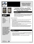
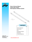
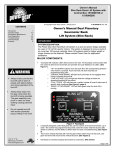
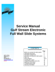
e-SYNC™
SLIDEOUT SYSTEM
SERVICE
MANUAL
82-S0347
09-02
TABLE OF CONTENTS
PAGE #
1
SERVICE MANUAL
1. SERVICE PARTS
2-4
2. REPLACEMENT PARTS & KITS
4
2.1 MECHANICAL COMPONENTS
4
2.2 ELECTRICAL COMPONENTS
4
2.3 GEARMOTORS
4
3. TROUBLESHOOTING THE SLIDEOUT SYSTEM
5-6
4. COMPONENT PART REPLACEMENT INSTRUCTIONS
8
8
4.1 GEARMOTOR
5. REQUIRED INFORMATION FOR ORDERING PARTS
9
APPENDIX
10-14
WARRANTY
15
FIGURES
Figure 1
Figure 2
Figure 3
2
3
7
SERVICE MANUAL
!!! CAUTION !!!
THE FOLLOWING INFORMATION IS FOR AUTHORIZED
RV DEALERS AND SERVICE TECHNICIANS.
RV OWNERS SHOULD NOT ATTEMPT THESE REPAIRS
OR PROCEDURES.
ANYONE OTHER THAN A RV AUTHORIZED SERVICE
TECHNICIAN ATTEMPTING REPAIRS WILL VOID
WARRANTY.
!!! CAUTION !!!
1
Fig. 1 - Typical e-SYNC™ Lo-Pro Rail Slideout System
(Motor orientation may be different)
2
Fig. 2 - Typical e-SYNC™ Tube Rail Slideout System
(Motor orientation may be different)
3
2. POWER GEAR SLIDEOUT SYSTEM REPLACEMENT KITS
2.1 MECHANICAL COMPONENTS
CONTACT POWER GEAR SERVICE FOR PART NUMBERS, REPLACEMENT PARTS,
AND SERVICE INFORMATION.
2.2 ELECTRICAL COMPONENT REPLACEMENT KITS
KIT P/N
DESCRIPTION
800003
KIT, ELECTRICAL, e-SYNC™
Contents of kit:
Description
HARNESS CNTL BOX TO MTR
CNTRL BOX DUAL MTR
Quantity per Kit
2
1
2.3 REPLACEMENT GEARMOTORS
MOTOR P/N
DESCRIPTION
522609
MOTOR ASSY DS MT e-SYNC™
4
Quantity per System
2
3. TROUBLESHOOTING THE SLIDEOUT SYSTEM
If a problem occurs with a Power Gear Slideout System Consult the following table. If a problem is not listed or you require further
assistance, please call Power Gear and talk to our Customer Service Department at 1-800-334-4712.
NOTE: BEFORE REPLACING PARTS ON THE SLIDEOUT SYSTEM MAKE SURE THE BATTERY HAS BEEN DISCONNECTED.
Problem
Check/Inspect
Electrical wiring and
components.
Probable Cause
Bad wiring or components.
Excessive drag on the room.
The room will move slightly
then stop.
The room does NOT
move and the motor
does NOT turn.
Motor turns but gear shaft does
not turn.
Spur gear spins freely on shaft.
Check for motor brake lever in
‘
engaged’position.
The room does
NOT seal.
One side seals and the other
side does not seal.
Gear shaft pin or coupler
broken.
Pin in motor output shaft
broken.
Sheared Woodruff key.
Motor brake lever
disengaged.
Stops not programmed
correctly.
Room height misadjusted.
Room/opening not square.
5
Solution
Check wiring and components.
Check to insure the transit bars
are removed.
Check for proper fit of room.
Refer to TIP sheet #82
Replace motor/gear shaft.
Refer to replacement instructions.
Replace gearmotor assembly.
Refer to replacement instructions.
Replace key and reprogram stops.
Refer to replacement instructions.
Engage brake lever.
Refer to Fig. 3
Reprogram stops.
Refer to TIP sheet #167
Check for proper room height.
Refer to TIP sheet #82
Measure room/opening for proper fit.
Problem
Check/Inspect
The room STARTS
to move but then
STOPS.
Test by visual inspection.
The room moves
VERY slowly.
System makes a
LOUD chatter noise
When operating.
The room moves slowly when it
is nearly in or beginning to go
out.
The room moves slowly all the
way in or out.
Check the slideout room height
adjustment.
Probable Cause
Transit bar still installed.
An obstruction blocking
path of travel of the room.
Debris lodged between the
gear and rack.
Dirt or corrosion build-up.
Improper room height
setting, rails are pinching.
Room is binding.
Check for 12 Volts DC at the
motor while room is in
operation. If not 12 volts...
Slideout room height out of
adjustment.
6
Solution
Remove transit bar.
Remove obstruction or
relocate the unit.
Remove the debris.
Remove dirt and lubricate
with LIGHT coat of oil.
Check for proper room height.
Refer to TIP sheet #82
Adjust item binding room.
Recharge or replace battery.
Check wiring harnesses.
Readjust slideout room.
Refer to TIP sheet #82
!!! WARNING !!!
WHEN THE MOTOR BRAKE IS DISENGAGED THE SLIDEOUT ROOM WILL NOT LOCK
INTO PLACE; THEREFORE, THE ROOM WILL NOT BE SEALED. WHEN THE ROOM HAS
BEEN MANUALLY RETRACTED, BE SURE TO INSTALL THE TRANSIT BARS (IF SO
EQUIPPED) AND RETURN THE MOTOR BRAKE LEVER TO ITS NORMAL ENGAGED
POSITION IN ORDER TO SEAL AND LOCK THE ROOM INTO POSITION.
Fig. 3 Motor Brake Lever
7
4. COMPONENT PART REPLACEMENT INSTRUCTIONS
NOTE: BEFORE REPLACING PARTS ON THE SLIDEOUT SYSTEM MAKE SURE
THE BATTERY HAS BEEN DISCONNECTED.
4.1 Replacing the Electric Gearmotor
1. Disconnect battery.
2. Disconnect motor harness.
3. Remove the (4) motor mounting bolts with a ½”socket/wrench and remove
the gearmotor.
4. Install the new gearmotor and bolt into place. NOTE: Refer to Part Ordering
Information in Section 5.
5. Check to ensure the brake lever on the motor is in the engaged position.
6. Reconnect the motor harness.
7. Reconnect the battery and test the system operation.
8. Reprogram the in and out stops for the new motor. NOTE: Refer to TIP
Sheet #167 for programming instructions.
8
5. REQUIRED INFORMATION FOR ORDERING PARTS
WHEN ORDERING PARTS, PLEASE PROVIDE THE FOLLOWING INFORMATION:
YOUR NAME
COMPANY NAME
PHONE NUMBER
SHIPPING ADDRESS
BILLING ADDRESS
PURCHASE ORDER NUMBER
FOR EACH PART NEEDED:
COACH / TRAILER
VIN or S/N
MAKE
MODEL
WHEEL BASE (IF APPLICABLE)
MILEAGE (IF APPLICABLE)
SINGLE OR DOUBLE RAIL SLIDEOUT SYSTEM
SIDE OF COACH / TRAILER THE SLIDEOUT ROOM IS ON (ROADSIDE OR
CURBSIDE)
PART NUMBER
DESCRIPTION
QUANTITY
NOTE
ALL REPAIRS MUST BE MADE BY AN AUTHORIZED SERVICE CENTER. SYSTEMS
THAT HAVE BEEN TAMPERED WITH, MODIFIED, ADJUSTED OR REPAIRED BY
ANY PARTY OTHER THAN AN AUTHORIZED SERVICE CENTER WILL VOID ALL
WARRANTIES.
9
APPENDIX
TIP SHEET # DESCRIPTION
PAGE #
82
SLIDEOUT ROOM HEIGHT ADJUSTMENT
11
167
e-SYNC™ INITIALIZATION PROCEEDURE
12
168
e-SYNC™ INSTALLATION AND TROUBLESHOOTING
13-14
10
SLIDE-OUT ROOM HEIGHT ADJUSTMENT
For proper slide-out operation the slide-out room floor to slide-out rail height must be set.
This procedure is to be performed at the factory during room installation and should be
checked periodically.
To set the room height please refer to the Figure below.
B=A
1/8"
0"
The distance between the bottom of the floor and the top of the inner rail must be the same
distance (A=B) or the distance at the end of the inner rail can be 1/8”greater than the inside
distance (B=A+1/8”).
Tip Sheet # 82
81-1299 REV. 2
11
1217 E. 7th Street
Mishawaka, IN 46544
Phone: 1-800-334-4712
1-888-339-2539
Fax:
574-256-6743
T.I.P. Troubleshooting Information on Power Gear
E-SYNC INITIALIZATION PROCEDURE
1.
Plug SETUP CONTROL harness into control box.
2.
Hold “CLEAR”, and push “ROOM OUT”or “ROOM IN”to clear stop settings.
3.
Plug both five pin Molex connectors from motors into control box. Motor on right side of slideout,
from out side of room, is plugged into plug zone next to the negative connection.
4.
When ”ROOM OUT”is pressed both pieces of steel must move out, if one or both of the arms
moves in the wrong direction, move the plug in that zone.
1.
Move room IN, using “ROOM IN”button, until seals are compressed, (use “MOTOR STOP”left
or right button to hold one motor while the other runs further, as necessary).
2.
Move room OUT, using “ROOM OUT”button, until inside fascia seal is compressed (use
“MOTOR STOP”left or right button to hold one motor while the other runs further, as necessary).
3.
Move room IN until desired position is reached; (use “MOTOR STOP”left or right button to hold
one motor while the other runs further, as necessary).
4.
Push and hold “SET”.
5.
While holding “SET”, push “ROOM IN”. This sets the room IN stop positions.
6.
Move room OUT until desired position is reached; (use “MOTOR STOP”left or right button to
hold one motor while the other runs further, as necessary).
7.
Push and hold “SET”.
8.
While holding “SET”, push “ROOM OUT”. This sets the room OUT stop positions.
9.
Procedure is complete.
NOTE:
Once the stop points are set operation is as follows;
The IN stops are used as the “room square”reference. During room travel, the slideout will be kept in
that relative relationship, during room extension and retraction. During room extension, if one of the set
points is further than the other, one tube will stop when it reaches its set point and the other will continue
moving until it reaches its set point. When first retracting the tube that has extended the furthest will move
until it reaches the “room square”reference, they will then move together synchronized until they both
reach the IN stop points.
12
TIP Sheet #167
82-S0343 -T REV. 0
07-02
1217 E. 7th Street
Mishawaka, IN 46544
Phone: 1-800-334-4712
1-888-339-2539
Fax:
574-256-6743
T.I.P. Troubleshooting Information on Power Gear
e-SYNC™ INSTALLATION AND TROUBLESHOOTING
1.
The location for the control box needs to be dry, away from the elements, and near enough to the
motors so that the 10 foot harnesses will reach. (Orientation of box is not important.)
2. Connection to control box is as follows:
a) Positive and negative terminals need to be connected to a 12V battery source.
b) The red, blue, and green wires need to be connected to the wires coming from the room slide out switch
using the attached butt splices.
3. Motor connections and initialization procedure can be found on TIP Sheet #167. More detailed
description of the motor connections can be found below.
Motor to Control Box Connections
Both motors outboard of rails:
Both motors to right side:
Both motors inboard of rails:
Both motors on left side:
13
TIP Sheet #168
82-S0344-T REV. 0
09-02
1217 E. 7th Street
Mishawaka, IN 46544
Phone: 1-800-334-4712
1-888-339-2539
Fax:
574-256-6743
T.I.P. Troubleshooting Information on Power Gear
Troubleshooting
Description of Problem
Solution
Motors will not run.
Check all connections.
Check in-line fuse to switch.
Check that harnesses are connected to proper plug
and that only one plug is each motor zone.
Need to reprogram out stops.
Need to reprogram in stops.
Reset controller.
Switch the blue and green wires going to the switch.
Switch one motor plug in its respective zone.
Room does not stop going out.
Room does not stop coming in.
After switching motor connections, nothing moves.
Motors run backwards from switch designation.
Motors run in opposite directions.
14
TIP Sheet #168
82-S0344-T REV. 0
09-02
POWER GEAR
LIMITED WARRANTY
Power Gear warrants to the original retail purchaser that the product will be free from defects in material and workmanship
for a period of one (1) year following the retail sales date. Power Gear will, at its option, repair or replace any part covered
by this limited warranty which, following examination by Power Gear or its authorized distributors or dealers, is found to be
defective under normal use and service. No claims under this warranty will be valid unless Power Gear or its authorized
distributor or dealer is notified in writing of such claim prior to the expiration of the warranty period. Warranty is nontransferable.
THIS WARRANTY SHALL NOT APPLY TO:
• Failure due to normal wear and tear, accident, misuse, abuse, or negligence.
• Products which are modified or altered in a manner not authorized by Power Gear in writing.
• Failure due to misapplication of product.
• Telephone, telegraph, teletype or other communication expenses.
• Living or travel expenses of person performing service.
• Overtime labor.
• Failures created by improper installation of the product’s slideout system or slideout room to include
final adjustments made at the plant for proper room extension/retraction; sealing interface between
slideout rooms and side walls; synchronization of inner rails; or improper wiring or ground problems.
• Failures created by improper installation of leveling systems, including final adjustments made at the
plant, or low fluid level, wiring or ground problems.
• Replacement of normal maintenance items including lubricants and fuses.
There is no other express warranty other than the foregoing warranty. THERE ARE NO IMPLIED WARRANTIES OF
MERCHANTIBILITY OR FITNESS FOR A PARTICULAR PURPOSE. IN NO EVENT SHALL POWER GEAR BE
LIABLE FOR ANY INCIDENTAL OR CONSEQUENTIAL DAMAGES. This warranty gives you specific legal rights, and
you may also have other rights which vary from state to state. Some states do not allow the limitations of implied warranties,
or the exclusion of incidental or consequential damages, so the above limitations and exclusions may not apply to you.
For service contact your nearest Power Gear authorized warranty service facility or call 1-800-334-4712. Warranty service
can be performed only by a Power Gear authorized service facility. This warranty will not apply to service at any other
facility. At the time of requesting warranty service, evidence of original purchase date must be presented.
Power Gear
a unit of APW Engineered Solutions
950 Green Valley Road
P.O. Box 695
Beaver Dam, WI 53916-0695
800/334-4712
15