1
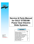
Automatic Hydraulic Leveling Operation Manual © Power Gear 12/07 #3010001460 Rev. 0A Automatic Hydraulic Leveling Operation Manual Touch Pad #500629 (140-1226) & Control Box 1010001284 CONTENTS Introduction Operating Safety System Operation Jack Retraction Manual Override Maintenance Troubleshooting Warranty ! 1 1 2 2 2-3 3 3-4 4 WARNING This is a leveling system only and is not intended to lift your coach tire(s) completely off the ground. Attempting to lift your coach completely off the ground (for example, to use this leveling system to change a tire) could cause damage to the system and serious injury to the parties involved. If a tire should require changing, please have the proper equipment and/or contact a professional. Introduction This coach is equipped with a Power Gear Hydraulic Leveling system that utilizes 4 power down, spring return jacks, hydraulic pump, controlbox and touchpad. Please read the entire operation manual prior to using your leveling system. Before You Level Your Coach 1. Engine must be running. 2. Park brake must be set and transmission must be in “park” (“neutral” for diesel coaches) before jacks will operate. 3. Check leveling site to make sure obstructions have been cleared away for proper jack operation. 4. Selecting a site: When the coach is parked on an excessive slope the leveling requirements may exceed the jack lift stroke capability. If the coach is parked on an excessive slope, the coach should be moved to a more level surface before the leveling system is deployed. ! WARNING 1. Keep people clear of coach prior to turning the leveling system on and while leveling system is in use. 2. Never expose hands or other parts of the body near hydraulic leaks. Highpressure oil leaks may cut and penetrate the skin causing serious injury. ! CAUTION 1. If your coach is equipped with a slide out(s) always level your unit first, and then operate the slide out room(s). When retracting the slide(s), always retract the room(s) first then retract the leveling jacks. Following this procedure will produce the least amount of stress on your chassis. 1217 E. 7th Street Mishawaka, IN 46544 888-334-4712 www.powergearus.com 2. Please read the owners’ manual from the manufacturer who built and designed your motor home for further leveling and slide out room operating information and safety features. Page 2 Automatic Hydraulic Leveling Operating Instructions Automatic mode button Front Jacks Button “LEVEL” Indicator Manual operation button (push and hold for 3-5 seconds) LEVELING YOUR COACH 1. Start the engine. Your leveling control will start a self check sequence indicated by the lights on the panel blinking in a rotating pattern. It will turn off when it has finished it’s self check within a few seconds. Right Jack Button 2. Push the "On/Off" button on control panel. The system is now operational and the “On/Off” LED will turn on. 3. Check to see that the engage park brake light is not illuminated. If so, engage the parking brake. (Your coach will have to be in neutral or park to operate the system). 4. Push the “AUTO” button. The automatic leveling system will begin it’s leveling procedure. Please avoid Rear Jacks Left Jack movement in the coach during automatic leveling as it Button Button can cause errors in operation. The green LEVEL indicator LED will illuminate when the auto levelilng Note: Visually inspect jacks process is complete. Check to make sure that all jacks are on the ground. Also to ensure all pads are touchcheck to make sure that no tire is off the ground. If so, your leveling process is ing ground. Should one of complete. If further adjustments are needed, refer to the “Manual Operation” section. the rear jacks not be touch5. You can then turn the system off by pushing the on/off button again. ing the ground, press the corresponding left or right Retracting Your Jacks rear jack buttons to lower the appropriate jack to the 1. Start the engine. ground. Never lift the wheels 2. Turn on the system by pushing the “on/off” button. The system is now operational off the ground to level the and the “On/Off” LED will turn on. coach. This can lead to an 3. Push the “ALL JACKS” retract button. When the “JACKS DOWN” light turns off, unsafe condition and visually check to make sure that all jacks have fully retracted. If so, your coach damage to the leveling leveling system is ready to travel. system or coach. Manual Operation NOTE: The right and left rear jacks are used to level the coach side to side. Pushing the “LEFT” button on the control panel will extend the left rear jack. Pushing the “RIGHT” button on the control panel will extend the right rear jack. There is no individual control of the right or left front jacks on 4 jack systems. Automatic pressure equalization built into the system automatically shifts the front jacks. There are certain conditions where manually leveling your coach may be desirable. Conditions where large amounts of side to side or front to rear leveling are necessary may work better using the manual leveling procedures that follows. 1. Start the engine. 2. Push the “On/Off” button to turn on the system. 3. Push and hold the “MANUAL” button for 3-5 seconds in order for the system to switch to the manual mode. It will signal that it is in the manual mode when the light under the “MANUAL” button is illuminated. 4. Push “FRONT” button until the front of the coach rises approximately 3 “. This is important and necessary to allow the coach to pivot when leveling side to side. If there is insufficient jack stroke to lift the front of the coach at least 3 inches the coach will have to be moved to an area with less front to rear slope. 5. Push the “REAR” button until both rear jacks contact the ground. 6. Level the coach from front to rear by pushing the “REAR” button if the light under the “REAR” button is illuminated. If the light is illuminated above the “FRONT “ button, push the “FRONT” button. In either case, keep button depressed until the green center “LEVEL” light is illuminated, or both front and rear lights have turned off. Page 3 Automatic Hydraulic Leveling NOTE: If the “Wait” light is ever flashing by itself, it means the control is busy and you cannot operate the jacks. After a short period of time (from 5 to 30 seconds), the “Wait” light will go off again, and you can resume operation as normal. 7. Level the coach from side to side by pushing the “RIGHT” button if the light beside the “RIGHT” button is illuminated. If the light beside the “LEFT” button is illuminated, push the “LEFT” button until the “LEVEL” light is illuminated. 8. Repeat steps 6 and 7 if needed. 9. Turn power off to leveling system by pushing “ON/OFF” button. 10. Visually inspect jacks to ensure all pads are touching ground. Should one of the rear jacks not be touching the ground, press the corresponding left or right rear jack buttons to lower the appropriate jack to the ground. Never lift the wheels off the ground to level the coach. This can lead to an unsafe condition and damage to the leveling system or coach. Preventative Maintenance ! WARNING Your coach should be supported at both front and rear axles with jack stands before working underneath, failure to do so may result in personal injury or death. 1. Check and/or fill the reservoir with the jacks and room(s) in the fully retracted position, each month. ATF fluid should be added to the top of the fill port on the reservoir. 2. Change fluid every 24 months (if necessary). 3. Inspect and clean all hydraulic pump electrical connections every 12 months. 4. Remove dirt and road debris from jacks as needed. 5. If jacks are down for extended periods, it is recommended to protect exposed leveling jack chrome rods with a silicone lubricant every 5 to 7 days for protection. 6. If your coach is located in a salty environment (within 60 miles of coastal areas), it is recommended to spray the rods every 2 to 3 days with a silicone lubricant. 7. Grease the fitting on the bottom of each jack cylinder with Lithium grease every 20-30 uses. Do not overfill. RECOMMENDED HYDRAULIC FLUIDS FOR YOUR HYDRAULIC PUMP Your unit is filled with Automatic Transmission Fluid (ATF) from the factory. In most applications, Type A automatic transmission fluid (ATF, Dexron III, etc.,) will work satisfactorily. Mercon V is also recommended as an alternative fluid for Power Gear hydraulic systems. Do not use “hydraulic oil” fluids in conjuction with ATF. If operating in cold temperatures (less than 10° F) the jacks may extend and retract slowly. For cold weather operation, fluid formulated for low temperatures may be desirable. Mobil DTE 11M, Texaco Rando HDZ 15HVI, Kendall Hyden Glacial Blu, or any Mil. Spec. H5606 hydraulic fluids are recommended for cold weather operation. Do not mix ATF and hydraulic oils. Please consult factory before using any other fluids than those specified here. Troubleshooting Locations of breakers, fuses, fuse panels, etc. are coach specific. Consult your coach owner’s manual or the coach manufacture for locations of these components. The following information will guide you to repairs that may be made on site. For problems not covered here, contact your service center or our website for more extensive troubleshooting information in the service manual for your system. PROBLEM System will not turn on, indicator light does not light. Jacks will not extend, pump is not running. PROBABLE CAUSE CORRECTIVE ACTION Coach ignition not in run position. Turn ignition to run position. Transmission not in park or neutral. Place transmission in park or neutral. Parking brake not set. Set brake. Control has been left on for more than four minutes, auto shut off. Push on/off button twice. Battery voltage is low. Recharge battery. Coach must be running. Page 4 Automatic Hydraulic Leveling PROBLEM PROBABLE CAUSE CORRECTIVE ACTION Jacks will not extend, pump is running. Fluid level low. Fill tank to proper level with Dexron III Automatic Transmission Fluid. All jacks will not retract or will not fully retract. System overfilled with fluid. Drain fluid to recommended level. Any one or two jacks will not retract at all. Weak or obstructed jack spring(s). Replace jack spring or remove obstruction. Jack rod guide is rusted or dirty. Clean chrome rod, grease rod guide if equipped with grease fittings. Otherwise lubricate with lithium grease. It may be necessary to reseal jack or replace. Any jack retracts very slowly Jack rod is rusted or dirty. Clean chrome rod, grease rod guide if equipped with grease fittings. Otherwise lubricate with lithium grease. It may be necessary to reseal jack or replace. Panel “jacks down” light illuminated, jacks are retracted. Low fluid level. Fill tank to proper level with Dexron III Automatic Transmission Fluid. Panel “jacks down” light and alarm on while driving, jacks retracted. Low fluid level. Fill tank to proper level with Dexron III Automatic Transmission Fluid. Power Gear Limited Warranty Power Gear warrants to the original retail purchaser that the product will be free from defects in material and workmanship for a period of (2) years. Labor to repair these components will be covered for two years. Power Gear will, at its option, repair or replace any part covered by this limited warranty which, following examination by Power Gear or its authorized distributors or dealers, is found to be defective under normal use and service. No claims under this warranty will be valid unless Power Gear or its authorized distributor or dealer is notified in writing of such claim prior to the expiration of the warranty period. Warranty is transferable pending documentation of original sale date of product. THIS WARRANTY SHALL NOT APPLY TO: • Failure due to normal wear and tear, accident, misuse, abuse, or negligence. • Products which are modified or altered in a manner not authorized by Power Gear in writing. • Failure due to misapplication of product. • Living or travel expenses. • Telephone or other communication expenses. • Overtime labor. • Failures created by improper installation of the product’s slideout system or slideout room to include final adjustments made at the plant for proper room extension/retraction; sealing interface between slideout rooms and side walls; synchronization of inner rails; or improper wiring or ground problems. • Failures created by improper installation of leveling systems, including final adjustments made at the plant, or low fluid level, wiring or ground problems. • Replacement of normal maintenance items. 1217 E. 7th Street Mishawaka, In 46544 800-334-4712 www.powergearus.com There is no other express warranty other than the foregoing warranty. THERE ARE NO IMPLIED WARRANTIES OF MERCHANTABILITY OR FITNESS FOR A PARTICULAR PURPOSE. IN NO EVENT SHALL POWER GEAR BE LIABLE FOR ANY INCIDENTAL OR CONSEQUENTIAL DAMAGES. This warranty gives you specific legal rights, and you may also have other rights, which vary from state to state. Some states do not allow the limitations of implied warranties, or the exclusion of incidental or consequential damages, so the above limitations and exclusions may not apply to you. For service contact your nearest Power Gear authorized warranty service facility or call 1-800-334-4712. Warranty service can be performed only by a Power Gear authorized service facility. This warranty will not apply to service at any other facility. At the time of requesting warranty service, evidence of original purchase date must be presented.