1
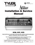
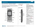
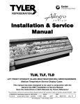
Installation & Service
Manual
NLH
LIFT FRONT CURVED GLASS HOT FOOD SERVICE MERCHANDISERS
Hot Temperature Service Display Cases
Save the Instructions in this Manual for Future Reference!!
This merchandiser conforms to the American National Standard Institute & NSF International Health and Sanitation standard ANSI/NSF 4 - 2003.
PRINTED IN Specifications subject to REPLACES
IN U.S.A.
change without notice. EDITION
11/05
ISSUE
DATE
5/07
Tyler Refrigeration * Niles, Michigan 49120
PART
NO.
9037169
REV.
B
ATTENTION
The information contained in this manual is provided by Custom Deli’s
Equipment, Inc. and is furnished by Tyler Refrigeration to our customers as a
reference manual only. Tyler Refrigeration assumes no responsibility or liability
for the accuracy or detail of the information contained herein. All information
contained in this manual is subject to change.
Installation & Service Manual
NLH
CONTENTS
Page
Specifications
NLH Specification Sheet . . . . . . . . . . . . . . . . . . . . . . . . . . . . . . . . 4
Installation Procedures
Inspect the Unit . . . . . . . . . . . . . . . . . . . . . . . . . . . . . . . . . . . . . . . . 5
Preliminary Location . . . . . . . . . . . . . . . . . . . . . . . . . . . . . . . . . . . . 5
Lift Glass Caution . . . . . . . . . . . . . . . . . . . . . . . . . . . . . . . . . . . . . . . 6
Lift Front Glass Leveling Instructions . . . . . . . . . . . . . . . . . . . . . . 7
Installation Check List . . . . . . . . . . . . . . . . . . . . . . . . . . . . . . . . . . . 8
Wiring Diagrams
NLH 4 208/240 Volt 60Hz 1Ph. 3W . . . . . . . . . . . . . . . . . . . . . . . . . 9
NLH 4 208/240 Volt 60Hz 3Ph. 4W . . . . . . . . . . . . . . . . . . . . . . . . 10
NLH 6 208/240 Volt 60Hz 1Ph. 3W . . . . . . . . . . . . . . . . . . . . . . . . 11
NLH 6 208/240 Volt 60Hz 3Ph. 4W . . . . . . . . . . . . . . . . . . . . . . . . 12
NLH 8 208/240 Volt 60Hz 3Ph. 4W . . . . . . . . . . . . . . . . . . . . . . . . 13
NLH 12 208/240 Volt 60Hz 3Ph. . . . . . . . . . . . . . . . . . . . . . . . . . . 14
Cleaning and Sanitation
Care and Upkeep . . . . . . . . . . . . . . . . . . . . . . . . . . . . . . . . . . . . . . 15
Food Stains . . . . . . . . . . . . . . . . . . . . . . . . . . . . . . . . . . . . . . . . . . 15
Stainless Steel Cleaning Precautions . . . . . . . . . . . . . . . . . . . . . . . 15
Steam Table Cleaning Instructions . . . . . . . . . . . . . . . . . . . . . . . 16
Cleaning Instructions . . . . . . . . . . . . . . . . . . . . . . . . . . . . . . . . . . . 16
Stainless Steel Cleaning Methods . . . . . . . . . . . . . . . . . . . . . . . . 16
General Information . . . . . . . . . . . . . . . . . . . . . . . . . . . . . . . . . . . . . . . . . 18
Proper Use of the Hot Food Deli Service Case . . . . . . . . . . . . . 19
Air Vent Adjustments . . . . . . . . . . . . . . . . . . . . . . . . . . . . . . . . . . . 19
Controls and Locations . . . . . . . . . . . . . . . . . . . . . . . . . . . . . . . . . 20
Steam Table Operation Instructions . . . . . . . . . . . . . . . . . . . . . . . 21
Service Instructions
Rear Sliding Door Removal and Installation . . . . . . . . . . . . . . . 22
Lift Glass Hinge Replacement . . . . . . . . . . . . . . . . . . . . . . . . . . . 23
Lift Glass Replacement . . . . . . . . . . . . . . . . . . . . . . . . . . . . . . . . . 24
Parts Information
Operational Parts List . . . . . . . . . . . . . . . . . . . . . . . . . . . . . . . . . . 25
Cladding and Trim Parts List . . . . . . . . . . . . . . . . . . . . . . . . . . . . . 26
Warranty . . . . . . . . . . . . . . . . . . . . . . . . . . . . . . . . . . . . . . . . . . . . . . . . . . 28
The following Lift Glass Hot Food Service Merchandiser models are covered in this
manual:
MODEL
DESCRIPTION
NLH
4’, 6’, 8’ & 12’ LIFT GLASS HOT FOOD SERVICE MERCHANDISER
May, 2007
Page 3
NLH
SPECIFICATIONS
NLH Lift Front Curved Glass Hot Food Service Merchandisers
Page 4
April, 2008
Installation & Service Manual
NLH
INSTALLATION PROCEDURES
Inspect the Unit
Preliminary Location
The unit should be carefully examined for
damage sustained during transit, before
and after unloading. The carrier must be
immediately notified of any damage and the
delivery receipt should be ammended noting
the unit was received in damaged condition.
The unit is shipped on a skid and in some
cases with end steel channel braces. The
unit should be located as closely as possible
to its final location before any crating and
bracing is removed.
The carrier should also be notified if
concealed damage is discovered.
This fixture is designed to display food
in or below the food pans only. Food
displayed above the level of the food pans
may not maintain proper temperatures!
CAUTION
• This unit is not constructed to support any
top load, therefore any weight in excess of
25 pounds, such as a person on top, or
other equipment placed on the top, could
cause damage to the unit and serious
personal injury.
• Your “Deli” case is designed and classified
as short term equipment, enclosed and
electrically heated, which when preheated,
is intended to receive food at no less than
180°F (82°C) and hold the food at not less
than 140°F (60°C) when connected to a
power source.
• This case does not have the thermal
capacity to heat food rapidly, but is
designed to hold food at the desired temperature once the food has been heated
throughout using some other device.
• Foods that have been cooked and refrigerated should be reheated rapidly to 170°F
or higher throughout before being placed
in your “deli” case.
• In accordance with ANSI/NSF 4 - 2003
from the FOOD SERVICE AND
SANITATION MANUAL.
November, 2005
Page 5
NLH
CAUTION
NOTICE TO INSTALLER & OPERATOR!
• DO NOT LEAVE GLASS RAISED AND UNATTENDED.
• NOTICE FRONT EDGE WHEN WORKING NEAR RAISED
GLASS.
This case is designed so the front glass can be raised for cleaning and
merchandising only. It is recommended that any cleaning or merchandising be done when the store is closed. If this is not possible, then it should
be done at a time when customer traffic is low.
The raised glass should not be left unattended and should be
lowered whenever leaving the case.
The glass front edge is marked with bright tags to make it noticable when
in the raised position. These tags are not to be removed. Caution
should be used when working or walking near the raised glass as it projects in front of the case.
Page 6
May, 2007
Installation & Service Manual
NLH
Lift Front Glass Leveling Instructions
Accurate leveling is critical for the proper
operation of the lift glass on this case.
In some instances, setting the case on an
apparently level floor can cause the lift glass
to fit improperly. If there is any twist in the
body, it could cause the lift glass not to fit or
work properly.
The emphasis when leveling this case must
be on making sure the lift glass works and
seals properly.
If the lift glass still doesn’t close or line-up
properly, add shims to case corners.
Shimming will ensure proper operation and
alignment of the lift glass.
The handle on the lift glass must rest evenly
on the color band. Proper lift glass sealing is
essential for good product refrigeration.
NOTE
• Do not anchor the base to the floor or
enclose the case until the lift glass is fitting properly and working correctly.
• Make sure all lift glass hinge stops have
been removed to ensure proper operation.
To remove lift glass hinge stops:
1. Open rear of fixture and locate the hinge
assemblies (2 on 4’ glass and 3 on 6’
glass).
The case should be leveled across the top
(1), close to the hinge, and on the color band
(2). A 4 foot level is recommended, and both
places should be level! This will enable the
lift glass to fit and work properly.
November, 2005
2. Remove all hinge stops (1) from the
shanks of the hex head bolts (2).
Page 7
NLH
Installation Check List
In addition to the standard practices which should be used in the
installation of this case, the installer should pay particular attention to
the following items:
Is water connected to a hot water feed for wet operation?
Is the lower well thermostat set for 180-190°F?
Is the top heat at the factory setting of 6 1/2?
Is the voltage correct at 208V or 230V to match heater ratings?
Are rear vents open for wet operation?
Is food being introduced to the wells at temperatures above 140°F?
SAVE TIME - AVOID CALL BACKS
Page 8
May, 2007
Installation & Service Manual
NLH
WIRING DIAGRAMS
NLH-4 208/240 Volt 60Hz 1Ph. 3W
November, 2005
Page 9
NLH
NLH-4 208/240 Volt 60Hz 3Ph. 4W
Page 10
May, 2007
Installation & Service Manual
NLH
NLH-6 208/240 Volt 60Hz 1Ph. 3W
November, 2005
Page 11
NLH
NLH-6 208/240 Volt 60Hz 3Ph. 4W
Page 12
May, 2007
Installation & Service Manual
NLH
NLH-8 208/240 Volt 60Hz 3Ph. 4W
November, 2005
Page 13
NLH-12 208/240 Volt 60Hz 3Ph.
Page 14
November, 2005
Installation & Service Manual
NLH
CLEANING AND SANITATION
Care and Upkeep
Wells operated moist will contain oxide (lime)
and other salts from the evaporating water.
Use detergents, mild abrasive cleaners or
Bon Ami to remove food which accidentally
spills into wells. DO NOT USE ORDINARY
STEEL WOOL PADS because they may
cause corrosion of the wells.
Never put food directly into the wells. Always
use food pans. Never let spilled food harden
or bake into stainless steel as it will cause
pitting of the surface.
When hard water evaporates in a unit, it often
leaves a mineral deposit. If this deposit is not
removed it can shorten the life of the heating
elements greatly. To remove this, swab or
cover the bottom of the unit with a water
solution containing vinegar (about 25% by
volume). Follow with cleansing powder,
then wash, rinse and dry.
Wells operated dry will discolor or brown at
the operating temperatures within the range
of this unit. To clean, use detergents, mild
abrasive cleansers, or Bon Ami.
With only a little care, your stainless steel hot
case will remain clean and bright and provide
you with excellent service for many years to
come.
Food Stains
Foods that burn and stick on other metals
can discolor stainless steel too. But with a
stainless steel unit you can remove discoloration by applying a mildly abrasive cleanser
such as Bon Ami. To soften an extremely
hard layer of burnt-on grease, cover the layer
with an ammonia soaked cloth for 10 to 15
minutes. You may also use a plastic or
stainless steel sponge. Then wash and dry
the surface as usual.
November, 2005
Stainless Steel Cleaning Precautions
1. Strong bleaches tend to corrode many
materials and should not come in contact
with stainless steel sinks or utensils
longer than 30 minutes. When these
chemicals are used, the stainless steel
should be rinsed thoroughly.
2. Tincture of iodine or iron should not
remain in contact with stainless surfaces.
These solutions, which cause stainless
steel to discolor, should be rinsed off
immediately after exposure.
3. Some foods, such as mustard, mayonnaise, lemon juice, vinegar and salt (or
dressings containing these ingredients)
will attack and corrode stainless steel.
You should never store them in stainless
containers.
4. Ordinary steel wool should be used
sparingly to clean stainless steel; because
particles may lodge in the surface and
rust. Allowing the wool to rest on a
stainless surface may cause a rusty
appearance. For difficult cleaning jobs
such as removing burned-on foods,
stainless steel “sponge” or pads are
recommended. When cleaning a highly
polished, mirror finish with a metal pad,
be especially careful that it does not
scratch the finish.
5. Gritty, hard abrasive will mar stainless
steel finish and are not recommended.
6. Sharp knives or choppers usually have
hard carbon steel edges and will leave
their mark on stainless surfaces.
Page 15
NLH
Steam Table Cleaning Instructions
When loading chicken into the case, use tongs to load individual pieces in a uniformed manner.
This will help prevent grease from building up on the case and the lights.
Make sure all infinite switch controls and flood lamps are in the “OFF” position. When unit is
“COOL” use a mild soapy solution to wipe off surface. DO NOT leave any soapy residue in the
case. Use a dry dish cloth to complete cleaning and wipe down.
** NEVER USE OVEN CLEANER. **
Clean all miscellaneous food particles out of stem table wells.
Never use “DRANO”, or any other type of drain cleaners in wells.
Never attempt to clean front glass while unit is hot. Use a quality glass cleaner.
It is very important to remove any grease splatter that may cling to the flood lamps.
Failure to do this may result in lamp overheating and premature deterioration. Do so
gently as excess force may cause damage to the bulbs.
Proper care and cleaning of your steam table will ensure longer life and prevent unnecessary
repairs.
Cleaning Instructions
WARNING
TYLER Refrigeration does not recommend the use of high pressure cleaning equipment on
display cases!! High pressure cleaners can penetrate and/or damage joint seals. Damaged
seals allow water leaks and/or air leaks that can cause poor case operation.
CAUTION
• When cleaning this case, try not to introduce water into the case faster than it can be
carried away by the waste outlet.
• Liquid chlorine bleach is corrosive to metals. The use of bleach or products containing
bleach will damage metal surfaces and void the case warranty.
• Sanitize the case with Quaternary Ammonium Solutions (ex: KAYQUAT II, J-512 Sanitizer,
SANIQUAT 512, etc...) approved per 21CFR 178.1010, followed by adequate draining and
air drying. These solutions may be obtained from Kay Chemical Co., Johnson Wax
Professional, Coastwide Laboratories, etc....
• Always use a soft cloth or sponge with mild detergent and water to clean any glass.
Never use abrasives or scouring pads to clean glass. They can scratch and/or damage
the glass.
See “General (UL/NSF) I&S Manual” for case cleaning instructions.
Stainless Steel Cleaning Methods
The cleaning data in the following stainless steel cleaning chart was supplied by AISI. The information was supplied by
Prime Metals Division, Alumax Aluminum Corporation.
TYPE OF CLEANING
CLEANING AGENT*
APPLICATION METHOD**
EFFECT ON FINISH
Routine cleaning
Soap, ammonia or detergent and water.
Sponge with cloth, then
rinse with clear water and
wipe dry.
Satisfactory for use on all
finishes.
Smears and fingerprints
Arcal 20, Lac-O-Nu, Lumin
Wash O’Cedar Cream
Polish, Stainless Shine
Rub with cloth as directed
on the package.
Satisfactory for use on all
finishes. Provides barrier film
Page 16
May, 2007
Installation & Service Manual
TYPE OF CLEANING
CLEANING AGENT*
NLH
APPLICATION METHOD**
EFFECT ON FINISH
Apply with damp sponge or
cloth.
Satisfactory for use on all
finishes.
Rub with damp cloth.
Satisfactory for use on all
finishes if rubbing is light.
Grade FFF Italian pumice,
whiting or talc
Rub with damp cloth.
Use in direction of polish lines
on No. 4 (polished) finish.
May scratch No. 2 (mill) and
No. 7 and 8 (polished) finishes.
Liquid NuSteel
Rub with dry cloth. Use a
small amount of cleaner.
Use in direction of polish lines
on No. 4 (polished) finish.
May scratch No. 2 (mill) and
No. 7 and 8 (polished) finishes.
Paste NuSteel or DuBois
Temp
Rub with dry cloth. Use a
small amount of cleaner.
Use in direction of polish lines
on No. 4 (polished) finish.
May scratch No. 2 (mill) and
No. 7 and 8 (polished) finishes.
Cooper’s Stainless Steel
Cleaner, Revere Stainless
Steel Cleaner
Apply with damp sponge or.
cloth.
Use in direction of polish lines
on No. 4 (polished) finish.
May scratch No. 2 (mill) and
No. 7 and 8 (polished) finishes.
Stubborn spots and
Allchem Concentrated
stains, baked-on
Cleaner
splatter, and other light
discolorations
Samae, Twinkle, or Cameo
Copper Cleaner
Grade F Italian pumice, Steel Rub with a damp cloth.
Bright, Lumin Cleaner, Zud or
Restoro
Use in direction of polish lines
on No. 4 (polished) finish.
May scratch No. 2 (mill) and
No. 7 and 8 (polished) finishes.
Penny-Brite or Copper-Brite
Rub with a dry cloth. Use a
small amount of cleaner.
Use in direction of polish lines
on No. 4 (polished) finish.
May scratch No. 2 (mill) and
No. 7 and 8 (polished) finishes.
Penny-Brite or Copper-Brite
Rub with a dry cloth.
Use in direction of polish lines
on No. 4 (polished) finish.
May scratch No. 2 (mill) and
No. 7 and 8 (polished) finishes.
Paste NuSteel or DuBois
Temp
Rub with dry cloth. Use a
small amount of cleaner.
Use in direction of polish lines
on No. 4 (polished) finish.
May scratch No. 2 (mill) and
No. 7 and 8 (polished) finishes.
Revere Stainless Steel
Cleaner
Apply with a damp sponge
or cloth.
Use in direction of polish lines
on No. 4 (polished) finish.
May scratch No. 2 (mill) and
No. 7 and 8 (polished) finishes.
Allen Polish, Steel Bright,
Wyandotte or Zud
Rub with a damp cloth.
Use in direction of polish lines
on No. 4 (polished) finish.
May scratch No. 2 (mill) and
No. 7 and 8 (polished) finishes.
Burnt-on foods and
grease, fatty acids,
milkstone (where swabbing or rubbing is not
practical)
Easy-Off, De-Grease-It, 4-6%
hot solution of such agents
as trisodium tripolyphospate,
or 5-15% caustic soda
solution
Apply generous coating.
Allow to stand for 10-15 min.
Repeated application may
be necessary.
Excellent removal, satisfactory
for use on all finishes.
Tenacious deposits,
rusty discolorations,
industrial atmospheric
stains
Oakite No. 33, Dilac, Texo 12,
Texo N.Y., Flash-Klenz,
Caddy Cleaner, Turco Scale
4368 or Permag 57.
Swab and soak with clean
cloth. Let stand 15 minutes
or more according to directions on package. Rinse
and dry.
Satisfactory for use on all
finishes.
Heat tint or heavy
discoloration
May, 2007
Page 17
NLH
TYPE OF CLEANING
CLEANING AGENT*
APPLICATION METHOD**
EFFECT ON FINISH
Hard water spots
and scale
Vinegar
Swab or wipe with a cloth.
Rinse with water and dry.
Satisfactory for use on all
finishes.
5% oxalic acid, 5% sulamic
acid, 5-10% phospheric acid,
or Dilac, Oakite No. 33,
Texo 12 or Texo N.Y.
Swab or soak with a cloth.
Let stand 10-15 minutes.
Always follow with neutralizer
rinse, and dry.
Satisfactory for use on all
finshes. Effective on tenacious
deposites or where scale has
built up.
Organic solvents such as
carbon tetrachloride, trichlorethylene, acetone, kerosene, gasoline, benzene,
alcohol and chlorethane n.u.
Rub with a cloth. Organic
solvents may be flammable
and/or toxic. Observe all
precautions against fire.
Do not smoke while vapors
are present. Be sure area
is well ventilated.
Satisfactory for use on all
finishes.
Grease and oil
*
Use of proprietary names is intended only to indicate a type of cleaner, and does not constitute an endorsement, nor is
omission of any proprietary cleanser to imply its inadequacy. It should be emphasized that all products should be used
in strict accordance with instructions on package.
**
In all applications a sponge or fibrous brush or pad are recommended. DO NOT use ordinary steel wool, steel brushes,
chlorine bleach or products containing bleach for cleaning or sanitizing stainless steel.
GENERAL INFORMATION
This manual will provide the installer, serviceman and user with information and assist in
the proper installation, servicing and use of
the Tyler-Custom Deli Equipment, Inc. Hot
Food Case.
As used herein, wet operation of this case
means that water is introduced into the hot
well and remains at a constant predetermined
level by means of an automatic water feeder.
Water vapor (steam) becomes the heat transfer medium. This is the most efficient means
of heat transfer with a minimum of product
dehydration.
CAUTION
The use of any medium other than water,
or the addition of substances to the water
to raise the boiling point could seriously
damage the wells.
Page 18
Dry operation of the case means that water is
not present in the heat well and the heat is
transferred by the air heated in the heat wells.
Models may be operated totally wet or totally
dry. If the well has been operated dry, the
wells must be allowed to cool to room temperature befroe converting to wet operation.
CAUTION
Introduction of cold water into a hot dry
well could cause the well to rupture and
severely damage the unit.
The heating of the well and the operation of
the overhead floodlamps are all controlled to
afford the operator maximum variation on
product placement flexibility and a wide variety of heat and humidity conditions to best
suit the food being merchandised.
May, 2007
Installation & Service Manual
A pilot light beside each control will glow
when the control is in any position other than
“OFF”. The heating elements below each
well have been sized and contained to
perform their function at highest efficiency
for maximum energy conservation. It is not
unusual for the element to shut off intermittently and come back on automatically as the
desired temperatur is maintained in the well.
In order to present the best appearance of
the pre-cooked convenience foods, as well as
to allow proper operation of the automatic
water feeder, make certain at installation that
the case is leveled front to back at each end.
Shim the base as required to obtain level.
Refer to page 7 in this manual for proper
leveling instructions.
Proper Use of the Hot Food Deli
Service Case
The choice of dry or moist heat and the
desired food maintenance varies with the type
of food, the water content od the food, other
personal preferences of the food manager
and the requirements of the local health
authorities. The National Sanitation Foundation (NSF) recommends maintenance of a
minimum of 140°F (60°C) in the food product.
Your Tyler-Custom Deli Equipment, Inc.
Hot Food Case is designed to enable the
conscientious operator to meet the most
rigorous demands for outstanding presentations and display of pre-cooked convenience
foods.
Do not attempt to cook foods in the “Deli”
Case. It is designed to maintain pre-cooked
foods at their taste tempting best condition in
a controlled heat and humidity atmosphere.
The experienced operator knows that
holding foods at elevated temperatures for
a prolonged period of time is a delicate
operation demanding operator skill, attention
and desire.
May, 2007
NLH
Normal wet operation at desired temperatures
leaves the front glass free of condensate. In
the event condensate does form as the case
is being brought to temperature for the day’s
operation, opening the rear doors should
clear the front glass quickly. Air vents are
provided at each end of the door tracks as
shown on this page. In the event that the
condensate reappears, check to make certain
that all wells being operated wet have food
pans in place. It is imperative your deli has a
complete compliment of food pans in each
well during “Wet” operation to minimize
steam loss and front glass condensation.
Check the temperature of the food in the
food pans to see that they are not too high,
indicating the temperature in the heat well
has the water at a hard boil.
Air Vent Adjustments
This model is equipped with two air vents;
one located at each end of the rear sliding
glass door opening.
Make certain that the air vents are
unobstructed.
Page 19
NLH
Controls and Locations
8 FOOT CASE SHOWN
1. Pilot Light: Glows when Thermostat is in any position other than OFF.
2. 150W Heat Lamps: Ranges from 0° to 100°.
3. Lower Well Heaters: Ranges from LO to HI.
4’ case has 3 wells
6’ case has 5 wells
8’ case has 7 wells
12’ case has 10 wells
4. Water Fill Valve: To be (Fill) horizontal position during wet operation
and (Drain) vertical position during dry operation.
5. Name Plate: Shows electrical information.
6. Toggle Switch: Turns on and off 60W interior top lights only.
7. 15 Amp Fuse: For interior lighting.
8. Electrical Junction Box.
Page 20
May, 2007
Installation & Service Manual
NLH
Steam Table Operation Instructions
**Start Up 45 Minutes Prior to Use.**
Auto Fill Water System
NOTE:
Unit must be level for system to operate
properly. See page 7.
1. To operate the Auto Fill systems, turn all Thandled valves to the “FILL” horizontal
position. Turn the field furnished 3/8” ball
valve to the “ON” fill position. It will take
approximately 30 minutes for the initial fill
up. But, once this is done all wells will
maintain a 2” water level automatically for
the rest of the days operation.
2. After all wells are full, cover all wells with
deli pans. Turn all flood lamps (small
black dials) to 100% (HIGH). Turn all
infinite switch controls (large black dials)
to #3 setting. #3 setting is the preheat
setting. After 45 minutes set all infinite
switch controls to LO setting.
NOTE
Infinite control switches for baked
chicken, fried chicken and meat
products should be left at the #3
setting. This is very important!
3. Now fill display pans with preheated
(cooked) product only. All product must
be at a minimum of 180°F going in the
steam table. Make sure all pans fit
properly.
4. Some adjustments may be required on
flood lamps during operations.
NOTE
Overhear flood lamps over baked and
fried chicken should be left at 100%
(HIGH). This is very important!
At the above setting all products should
maintain 145°F as required by most health
departments.
NOTE
There may be some condensation at
start-up when loading products.
Do not panic, it will go away.
May, 2007
Manual Fill With Filler Hose
1. Make sure all cutoffs (ball valves) on
drain system are in the “FILL” horizontal
position.
2. Fill each steam table well with 2 1/2” of
water using “FILLER HOSE”. Do not
over fill! Cover all wells with pan well
covers.
3. After filling steam table wells, turn all flood
lamps (small black dials) to 100% (HIGH).
Turn all infinite switch controls (large black
dials) to #3 setting. #3 setting is the
preheat setting. After 45 minutes, set all
infinite switch controls to LO setting.
NOTE
Infinite control switches for baked
chicken, fried chicken and meat
products should be left at the #3
setting. This is very important!
4. Now fill display pans with preheated
(cooked) product only. All product must
be at a minimum of 180°F going in the
steam table. Make sure all pans fit
properly.
5. Some adjustments may be required on
flood lamps during operations.
NOTE
Overhear flood lamps over baked and
fried chicken should be left at 100%
(HIGH). This is very important!
At the above setting all products should
maintain 145°F as required by most health
departments.
NOTE
There may be some condensation at
start-up when loading products.
Do not panic, it will go away.
6. To drain tubs, turn T-handled valves to the
“DRAIN” vertical position. This will allow
wells to drain.
NOTE
Prior to draining, turn all infinite switch
controls to “OFF” position.
Page 21
NLH
SERVICE INSTRUCTIONS
Rear Sliding Door Removal and Installation
The sliding doors come installed from the
factory in the door frame. These doors are
removable for cleaning and to aid in case
maintenance.
NOTE
DO NOT fully immerse doors when cleaning.
1. Remove the outer door by first sliding it to
the right end of the door frame (within an
inch of being closed).
2. Firmly grasp either side of the door and lift
into the upper track until it clears the lower
track.
Page 22
3. Tilt the door so that the bottom comes out
of the track.
4. Lower the door so that it seperates from
the upper track. The door should now be
free. Next remove the inner door in the
same manner.
5. To replace the doors, follow the above
steps in the reverse sequence. First
check to see that the sealing strips are in
their proper place. Remember to insert
the inner door first.
May, 2007
Installation & Service Manual
Lift Glass Hinge Replacement
NOTE
All product should be removed from the
case and the surrounding area before
making this repair.
1. Remove the lift glass by following the
instructions on the previous page.
2. Mark the position of the defective hinge
(1) on the top interior of the case.
3. Remove screws (2) from back edge of
stainless steel top (3). Lift up and pull out
on back edge of stainless steel top (3) to
remove it from top of case (4).
4. Remove four screws (5) from top of case
(4) and remove defective hinge assembly
(1) from inside top of case (4).
May, 2007
NLH
WARNING
Do not take hinge apart! The glass
assembly is extremely heavy and could
fall without proper support. Glass breakage and/or personal injury could result.
5. Position new hinge assembly (1) inside
top of case (4) as marked during removal
and secure with four screws (5). After
rechecking the hinge positioning, tighten
the four screws (5) to 125 lb-in. of torque.
6. Push front edge of stainless steel top (3)
under “T” rail (6) and insert back edge
behind door frame trim. Secure stainless
steel top (3) with screws (2).
7. Install the lift glass by following the
instructions on the previous page.
Page 23
NLH
Lift Glass Replacement
NOTE
If lift glass is shattered, start with step 1,
otherwise start with step 2 to replace the
lift glass.
1. Pull down the glass frame clamp (1) by
applying significant force at the hinge
assemblies (2). The hinge assemblies
are located inside the rear at the top of
the fixture. Hold hinges down until step
2 is performed.
2
Place the metal hinge stops (3), shipped
with the glass, over the shank of the
center bolt (4) at the rear of each hinge
assembly (2). This prevents the hinges
from popping upright when the lift glass
is removed.
3. While holding glass, remove screws (5)
from hinges (2) and glass frame clamp
(1).
4. Replace broken lift glass (6) with new lift
glass (6).
Page 24
WARNING
Wear safety glasses and gloves and use at
least two people when replacing glass.
Glass is heavy and weight distribution is
uneven. Mishandling of glass could cause
breakage and/or personal injury.
5. Install screws (5) in hinges (2) and glass
frame clamp (1). Tighten each hingescrew (5) to 60 lb-in. of torque. Do not
overtighten.
6. Check torque of glass frame clamp
setscrews (7). It should be pre-torqued
to 145 lb-in. Do not overtighten.
NOTE
Lift glass must seal tightly to ensure
proper operating temperatures! 5/8”
replacement seals are available through
TYLER Service Parts.
7. After the lift glass has been replaced,
remove the metal hinge stops (3). Make
sure the lift glass wipers overlap and seals
tightly against the color band.
August, 2007
Installation & Service Manual
NLH
PARTS INFORMATION
Operational Parts List
Case Usage
Domestic
Electrical Circuit
Case Size
115 Volt 60 Hertz
4’
6’
8’
12’
Fuse Holder
5217932
5217932
5217932
5217932
Fuse
5614129
5614129
5614129
5614129
Toggle Switch
5093834
5093834
5093834
5093834
“T” Handle*
5093841
5093841
5093841
5093841
Infi-Switch*
5093830
5093830
5093830
5093830
Reostat Switch*
5093836
5093836
5093836
5093836
Steam Table, assembled
includes Heat Element,
Insulation & Electrical Wires*
5093832
5093832
5093832
5093832
Steam Table, unassembled
Table Pan Only*
5093831
5093831
5093831
5093831
Heat Element, Wet & Dry Units*
5093829
5093829
5093829
5093829
Heat Element. Dry Unit Only*
5093837
5093837
5093837
5093837
Reservoir, Auto-Fill*
5093842
5093842
5093842
5093842
Float, Auto-Fill*
5093844
5093844
5093844
5093844
3-Way Valve*
5093840
5093840
5093840
5093840
Red Pilot Light
5093833
5093833
5093833
5093833
* = (1) per well
For information on operational parts not listed above contact the TYLER Service Parts
Department.
May, 2007
Page 25
NLH
Cladding and Trim Parts List
Item Description
NLH
4’
6’
8’
12’
9025045
9025052
9025058
9025061
1
Bumper Retainer
2
Screw
3
Color Band, Painted
9025231
9025232
9025233
9025234
4
Color Band Backer, Ptd
9025654
9025654
9025654
9025654
5
Bumper
-------------------
color by order
-------------------
6
Bumper End Trim
-------------------
color by order
-------------------
7
Upper Front Cladding, Ptd
Screw
9025833 (10) 9025833 (12) 9025833 (16) 9025833 (24)
----
9024922
5183536 (6)
5183536 (8)
9024923
9024924
5183536 (9) 5183536 (11)
8
Front Kickplate
----
9024968
9024969
9042970
9
Lwr. Cladding, Std. Ptd.
----
9043822
9043823
9043824
Lwr. Cladding, Opt. Ptd.
----
9043825
9043826
9043827
Upr. Cladding End Trim
9043828
9043828
9043828
9043828
9024814 (2)
9024814 (2)
9024814 (2)
9024814 (2)
Lwr. Cladding End Trim, Std. 9045049
9045049
9045049
9045049
Lwr. Cladding End Trim, Opt. 9045045
9045045
9045045
9045045
9024814 (2)
9024814 (2)
9024814 (2)
9024814 (2)
9043066
9043066
9043066
9043066
RH Base End Close-off, Ptd. 9043968
9043968
9043968
9043968
Opt. Base End Close-off, Ptd. 9024980
9024980
9024980
9024980
10
Screw
11
Screw
12
LH Base End Close-off, Ptd.
Page 26
May, 2007
Installation & Service Manual
May, 2007
NLH
Page 27
NLH
WARRANTY
Seller warrants that each new item of equipment and parts manufactured by
Seller hereunder shall be free from defects in material and workmanship.
Seller’s obligation under this warranty shall be limited solely, at Seller’s option,
to repairing or replacing F.O.B. Seller’s place of business, or allowing credit for,
any part which under normal and proper use and maintenance, proves defective
in material and workmanship, within one year from date of original shipment,
provided, that notice of any such defect and satisfactory proof thereof is
promptly given to Seller and thereafter such part is returned to Seller, at its
request, with transportation charges prepaid and Seller’s examination proves
such part to have been defective.
This warranty does not apply: (1) to used products ordered hereunder; (2) to
damage to any new product or part caused by overloading, abuse, misuse,
tampering, neglect or accident, or putting to a use other than normally
recommended by Seller; (3) to any product or part which shall have been
repaired, or altered or assembled in any way by other than the Seller, Seller’s
supplier or Seller’s installation contractor which, in the sole judgement of Seller
affects the performance, stability or purpose for which it was manufactured; (4)
toward payment of any removal or installation charges of warranted parts; (5) to
loss of food or contents of the equipment due to failure for any reason; (6) to
the condensing unit used with said equipment unless same was furnished by
the Seller; (7) when operation of the equipment covered by this order is
impaired due to improper drain installation. Used products are sold on an
“as is” basis unless otherwise expressly stated on the face hereof.
This warranty is in lieu of all other warranties (except of title),
expressed or implied, including any implied warranty of merchantability or fitness for a particular purpose, and in no event shall
Seller be liable for consequential or special damages. Seller makes no warranty
whatsoever in respect to items not manufactured by Seller, by instead the
applicable warranties, if any, of the respective manufacturers thereof shall apply.
Page 28
May, 2007