1
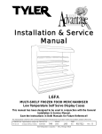
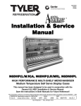
Installation & Service
Manual
NHMGHP
TOP DISPLAY MEAT/DELI/CRITICAL TEMP PRODUCE/
HIGH PERFORMANCE MERCHANDISERS
Medium Temperature Self Serve Display Cases
This manual has been designed to be used in conjunction with the
General (UL/NSF) Installation & Service Manual.
Save the Instructions in Both Manuals for Future Reference!!
This merchandiser conforms to the American National Standard Institute & NSF International Health and Sanitation standard ANSI/NSF 7 - 2003.
PRINTED IN Specifications subject to REPLACES
IN U.S.A.
change without notice. EDITION
7/06
ISSUE
DATE
4/07
Tyler Refrigeration * Niles, Michigan 49120
PART
NO.
9605849
REV.
C
NHMGHP
CONTENTS
Page
Specifications
NHMGHP Specification Sheets . . . . . . . . . . . . . . . . . . . . . . . . . . . . . . . . 4
Line Sizing Requirements . . . . . . . . . (See General-UL/NSF I&S Manual)
Pre-Installation Responsibilities . . . . . . . . (See General-UL/NSF I&S Manual)
Installation Procedures
Carpentry Procedures . . . . . . . . . . . . . . . . . . . . . . . . . . . . . . . . . . . . . . 6
Case Pull-Up Locations . . . . . . . . . . . . . . . . . . . . . . . . . . . . . . . . . . . . . 6
Plumbing Procedures . . . . . . . . . . . (See General-UL/NSF I&S Manual)
Refrigeration Procedures . . . . . . . . (See General-UL/NSF I&S Manual)
Electronic Thermostat Control . . . . . . . . . . . . . . . . . . . . . . . . . . . . . . . . 6
Bottom Trays . . . . . . . . . . . . . . . . . . . . . . . . . . . . . . . . . . . . . . . . . . . . . 7
Electrical Procedures . . . . . . . . . . . . . . . . . . . . . . . . . . . . . . . . . . . . . . 7
Electrical Considerations . . . . . . . . . . . . . . . . . . . . . . . . . . . . . . . . . . . . 7
Defrost Information . . . . . . . . . . . . . . . . . . . . . . . . . . . . . . . . . . . . . . . . . . . . . 8
Defrost Control Chart . . . . . . . . . . . . . . . . . . . . . . . . . . . . . . . . . . . . . . . 8
Installation Procedure Check Lists . . (See General-UL/NSF I&S Man.)
Wiring Diagrams . . . . . . . . . . . . . . . . . . . . . . . . . . . . . . . . . . . . . . . . . . . . . . . 8
NHMGHP Domestic & Export (50Hz) Case Circuits . . . . . . . . . . . . . 9
Cleaning and Sanitation . . . . . . . . . . . . . . (See General-UL/NSF I&S Manual)
Component Removal and Installation Instructions for Cleaning . . 11
Screens and Bottom Trays . . . . . . . . . . . . . . . . . . . . . . . . . . . . . . . . . . 11
Front Air Duct . . . . . . . . . . . . . . . . . . . . . . . . . . . . . . . . . . . . . . . . . . . . 11
Rear Duct Panels . . . . . . . . . . . . . . . . . . . . . . . . . . . . . . . . . . . . . . . . . . 11
Discharge Air Honeycomb . . . . . . . . . . . . . . . . . . . . . . . . . . . . . . . . . . 11
Lower Cladding . . . . . . . . . . . . . . . . . . . . . . . . . . . . . . . . . . . . . . . . . . 11
Upper Cladding
. . . . . . . . . . . . . . . . . . . . . . . . . . . . . . . . . . . . . . . . . 11
Cleaning Instructions . . . . . . . . . . . . . . . . . . . . . . . . . . . . . . . . . . . . . 12
Stainless Steel Cleaning Methods . . . . . . . . . . . . . . . . . . . . . . . . . . 12
Page 2
April, 2007
Installation & Service Manual
NHMGHP
Page
General Information
NSF Product Thermometer . . . . . . . . . . . . . . . . . . . . . . . . . . . . . . . . . 14
Radiant Heat Information . . . . . . . . . . . . . . . . . . . . . . . . . . . . . . . . . . 14
Radiant Heat Measurement . . . . . . . . . . . . . . . . . . . . . . . . . . . . . . . . . 15
Display Practices . . . . . . . . . . . . . . . . . . . . . . . . . . . . . . . . . . . . . . . . . 15
Service Instructions
Preventive Maintenance . . . . . . . . . (See General-UL/NSF I&S Manual)
Fan Blade and Motor Replacement . . (See Gen.-UL/NSF I&S Manual)
Color Band and Bumper Replacement (See Gen.-UL/NSF I&S Manual)
Anti-Sweat Replacement . . . . . . . . . . . . . . . . . . . . . . . . . . . . . . . . . . . 15
Front Glass Replacement . . . . . . . . . . . . . . . . . . . . . . . . . . . . . . . . . 16
Parts Information
Operational Parts List . . . . . . . . . . . . . . . . . . . . . . . . . . . . . . . . . . . . . 17
Cladding and Trim Parts List . . . . . . . . . . . . . . . . . . . . . . . . . . . . . . . 18
TYLER Warranty . . . . . . . . . . . . . . . . . . . . (See General-UL/NSF I&S Manual)
The following Medium Temperature, Top Display High Performance Merchandiser
models are covered in this manual:
MODEL
DESCRIPTION
NHMGHP
6’ GLASS FRONT TOP DISPLAY HIGH PERFORMANCE MERCHANDISER
NHMGHP
8’ GLASS FRONT TOP DISPLAY HIGH PERFORMANCE MERCHANDISER
NHMGHP
12’ GLASS FRONT TOP DISPLAY HIGH PERFORMANCE MERCHANDISER
April, 2007
Page 3
NHMGHP
SPECIFICATIONS
NHMGHP Top Display High Performance Medium Temp Merchandisers
Page 4
April, 2008
Installation & Service Manual
April, 2008
NHMGHP
Page 5
NHMGHP
INSTALLATION PROCEDURES
Carpentry Procedures
Case Pull-Up Locations
Electronic Temperature Control
Whenever an NHMGHP uses an electronic
thermostat and solenoid valve for temperature control, use the following instructions to
properly set-up the electronic thermostat.
Setting the Electronic Thermostat
1. Remove the four screws and cover from
the electronic thermostat.
2. Connect sensor wires to the common
(COM) and sensor (SEN) terminals of the
terminal strip located at the top left of the
printed circuit board. The sensor leads
are interchangeable.
The NHMGHP models have two pull-ups at
each end of the case. Pull-ups A and B are
located as shown and should be installed and
tightened starting with A and finishing with B.
See “General-UL/NSF I&S Manual” for lineup assembly instructions.
Refrigeration Procedures
Refrigeration system and superheat instructions can be found in the “General-UL/NSF
I&S Manual”. Electronic temperature control
information is listed below.
3. Set the Heating/Cooling jumper blocks to
the “COOL” position.
4. Set the Cut-in at Setpoint/Cut-out at
Setpoint jumper blocks to the “Cut-out at
Setpoint” position.
5. Set the keypad Locked/Unlocked jumper
blocks to the “Unlocked” position.
6. Replace the electronic thermostat cover
and secure with four screws.
Page 6
April, 2007
Installation & Service Manual
NHMGHP
Bottom Trays
All bottom trays should be installed with the
lips down. This assures proper case operation and sanitary practices.
Electrical Procedures
Electrical Considerations
CAUTION
7. To adjust the setpoint:
a. Push the Menu Button. “SP” will flash
on the LCD display.
b. Push the Menu Button one more time
and a setpoint temperature will be
displayed.
c. Push the Up or Down Button until the
desired setpoint is displayed.
NHMGHP
= 27°F
d. Push the Menu Button.
8. To adjust the differential:
a. Push the Menu Button. “SP” will flash
on the LCD display.
b. Push the Down Button until “DIF” is
shown on the LCD display.
c. Push the Menu Button one more
time and a differential number will be
displayed.
d. Push the Up or Down Button until
the desired differential setting is
displayed. NHMGHP
(all applications)
= 2°F
d. Push the Menu Button.
With the cooling mode selected, the
differential is ABOVE the setpoint. The relay
will energize and the LED indicator will
illuminate when the temperature reaches the
differential setting. When the temperature
drops to the setpoint, the relay and LED
indicator will de-energize and refrigeration
will stop.
The settings above are specific to TYLER
NHMGHP cases. Other applications will
require different setpoints and differentials.
July, 2004
Make sure all electrical connections at
components and terminal blocks are tight.
This prevents burning of electrical terminals and/or premature component failure.
NOTE
The raceway houses the electrical wiring,
components and terminal blocks for the
case. Remove the lower front cladding to
access the raceway.
Case Fan Circuit
This circuit is to be supplied by an uninterrupted, protected 120V circuit. The case fan
circuit is not cycled, except when equipped
for gas defrost. On gas defrost cases the fan
circuit is controlled by a 50/40 klixon.
NOTE
With gas defrost, the fans will not start
until the coil temperature reaches 40°F at
the fan delay thermostat.
Fluorescent Lamp Circuit
NHMGHP optional canopy lighting is supplied
by a single row of T-8 electronic ballast lights.
It is controlled by a light switch in each
canopy light fixture.
Anti-Sweat Circuit
The NHMGHP cases have two anti-sweat
heaters. One in the rear riser for the discharge air and an additional anti-sweat heater
for the front glass. All anti-sweat heaters are
wired directly to the main power supply so
they can operate at all times.
Page 7
NHMGHP
CAUTION
Defrost Information
See “General-UL/NSF I&S Manual” for
operational descriptions for each type of
defrost control.
Defrost Control Chart
If electronic sensors are used in place of
the klixons, the sensors must be located in
the same location as the klixons for that
defrost type. Any other locations will
effect the refrigeration efficiency of the
case.
NHMGHP Defrost Option Settings
Defrost
Defrost Defrosts Duration
Per Day
(Min)
Type
Off Time
4
44*
Gas
4
15
WIRING DIAGRAMS
Term.
Temp.
----55°F
* See specification pages in this manual
for pump down adjustment variations.
ELECTRICIAN NOTE - OVERCURRENT
PROTECTION
120V circuits should be protected by 15 or 20 Amp
devices per the requirements noted on the cabinet
nameplate or the National Electrical Code, Canadian
Electrical Code - Part 1, Section 28. 208V defrost
circuits employ No. 12 AWG field wire leads for field
connections. On remote cases intended for end to
end line-ups, bonding for ground may rely upon the
pull-up bolts.
The following wiring diagram on page 9 and
10 covers the NHMGHP case circuits and
defrost circuits.
All klixons are located on the right end of the
evaporator coil. The diagram shows the location for each defrost type that uses a klixon.
NOTE
The termination thermostat for gas defrost
is located on the bypass check valve.
Page 8
April, 2007
NHMGHP Domestic & Export (50 Hz) Case Circuits (6’, 8’ & 12’ Cases)
April, 2007
Page 9
Page 10
April, 2007
Installation & Service Manual
CLEANING AND SANITATION
Component Removal and
Installation Instructions for
Cleaning
Screens and Bottom Trays
1. Remove product from screens or bottom
of case.
2. To remove screens, push up on each
screen until bottom tabs clear holes in
front duct, then remove screen from case.
To remove bottom trays, grasp and lift out
each of the bottom trays from the case
interior.
NHMGHP
Discharge Air Honeycomb
1. Loosen screws securing rear retainer
plate.
NOTE
Note position of the honeycomb grid during removal so it can be reinstalled the
same way.
2. Slide rear retainer plate back until the
honeycomb grid sections can be removed
from the top duct.
CAUTION
Improper installation of the honeycomb
grid section could result in improper air
flow and/or poor refrigeration.
Front Air Ducts
3. After cleaning, replace honeycomb grid
sections as they were removed and
secure with the rear retainer plate and
screws.
1. Remove lower trays, see this page.
Lower Cladding
2. Lift out front air duct sections.
1. Remove kickplate from kickplate supports. (See General-UL/NSF I&S Manual.)
3. After cleaning, replace bottom trays with
lips down in reverse order.
3. After cleaning, replace in reverse order.
Rear Duct Panels
1. Remove shelves and bottom trays, see
above.
2. Remove mounting screws and rear duct
panels from case.
3. After cleaning, replace and secure rear
duct panels in reverse order.
2. Remove mounting screws from top and
bottom of lower cladding and remove
lower cladding.
3. After cleaning, replace in reverse order.
Upper Cladding
1. Remove lower cladding, see above.
2. Remove color band, bumper and bumper
retainer from case. (See General-UL/NSF
I&S Manual.)
2. Remove mounting screws from top and
bottom of upper cladding and remove
upper cladding.
3. After cleaning, replace upper cladding
and remaining components in reverse
order.
July, 2004
Page 11
NHMGHP
Cleaning Instructions
CAUTION
• When cleaning this case, try not to introduce water into the case faster than it can be
carried away by the waste outlet.
• Liquid chlorine bleach is corrosive to metals. The use of bleach or products containing
bleach will damage metal surfaces and void the case warranty.
• Sanitizr the case with Quaternary Ammonium Solutions (ex: KAYQUAT II. J-512 Sanitizer,
SANIQUAT 512, etc...) approved per 21CFR 178.1010, followed by adequate draining and
air drying. These solutions may be obtained from Kay Chemical Co., Johnson Wax
Professional, Coastwide Laboratories, etc....
• Always use a soft cloth or sponge with mild detergent and water to clean the front glass.
Never use abrasives or scouring pads to clean glass. They can scratch and/or damage
the glass.
WARNING
TYLER Refrigeration does not recommend the use of high pressure cleaning equipment
on display cases!! High pressure cleaners can penetrate and/or damage the joint seals.
Damaged seals allow water leaks and/or air leaks that can cause poor case refrigeration.
See “General (UL/NSF) I&S Manual” for case cleaning instructions.
Stainless Steel Cleaning Methods
The cleaning data in the following stainless steel cleaning chart was supplied by AISI. The information was supplied by
Prime Metals Division, Alumax Aluminum Corporation.
TYPE OF CLEANING
CLEANING AGENT*
APPLICATION METHOD**
EFFECT ON FINISH
Routine cleaning
Soap, ammonia or detergent and water.
Sponge with cloth, then
rinse with clear water and
wipe dry.
Satisfactory for use on all
finishes.
Smears and fingerprints
Arcal 20, Lac-O-Nu, Lumin
Wash O’Cedar Cream
Polish, Stainless Shine
Rub with cloth as directed
on the package.
Satisfactory for use on all
finishes. Provides barrier film
Apply with damp sponge or
cloth.
Satisfactory for use on all
finishes.
Rub with damp cloth.
Satisfactory for use on all
finishes if rubbing is light.
Grade FFF Italian pumice,
whiting or talc
Rub with damp cloth.
Use in direction of polish lines
on No. 4 (polished) finish.
May scratch No. 2 (mill) and
No. 7 and 8 (polished) finishes.
Liquid NuSteel
Rub with dry cloth. Use a
small amount of cleaner.
Use in direction of polish lines
on No. 4 (polished) finish.
May scratch No. 2 (mill) and
No. 7 and 8 (polished) finishes.
Paste NuSteel or DuBois
Temp
Rub with dry cloth. Use a
small amount of cleaner.
Use in direction of polish lines
on No. 4 (polished) finish.
May scratch No. 2 (mill) and
No. 7 and 8 (polished) finishes
Cooper’s Stainless Steel
Cleaner, Revere Stainless
Steel Cleaner
Apply with damp sponge or.
cloth.
Use in direction of polish lines
on No. 4 (polished) finish.
May scratch No. 2 (mill) and
No. 7 and 8 (polished) finishes.
Stubborn spots and
Allchem Concentrated
stains, baked-on
Cleaner
splatter, and other light
discolorations
Samae, Twinkle, or Cameo
Copper Cleaner
Page 12
July, 2006
Installation & Service Manual
TYPE OF CLEANING
CLEANING AGENT*
APPLICATION METHOD**
NHMGHP
EFFECT ON FINISH
Grade F Italian pumice, Steel Rub with a damp cloth.
Bright, Lumin Cleaner, Zud or
Restoro
Use in direction of polish lines
on No. 4 (polished) finish.
May scratch No. 2 (mill) and
No. 7 and 8 (polished) finishes.
Penny-Brite or Copper-Brite
Rub with a dry cloth. Use a
small amount of cleaner.
Use in direction of polish lines
on No. 4 (polished) finish.
May scratch No. 2 (mill) and
No. 7 and 8 (polished) finishes.
Penny-Brite or Copper-Brite
Rub with a dry cloth.
Use in direction of polish lines
on No. 4 (polished) finish.
May scratch No. 2 (mill) and
No. 7 and 8 (polished) finishes.
Paste NuSteel or DuBois
Temp
Rub with dry cloth. Use a
small amount of cleaner.
Use in direction of polish lines
on No. 4 (polished) finish.
May scratch No. 2 (mill) and
No. 7 and 8 (polished) finishes.
Revere Stainless Steel
Cleaner
Apply with a damp sponge
or cloth.
Use in direction of polish lines
on No. 4 (polished) finish.
May scratch No. 2 (mill) and
No. 7 and 8 (polished) finishes.
Allen Polish, Steel Bright,
Wyandotte or Zud
Rub with a damp cloth.
Use in direction of polish lines
on No. 4 (polished) finish.
May scratch No. 2 (mill) and
No. 7 and 8 (polished) finishes.
Burnt-on foods and
grease, fatty acids,
milkstone (where swabbing or rubbing is not
practical)
Easy-Off, De-Grease-It, 4-6%
hot solution of such agents
as trisodium tripolyphospate,
or 5-15% caustic soda
solution
Apply generous coating.
Allow to stand for 10-15 min.
Repeated application may
be necessary.
Excellent removal, satisfactory
for use on all finishes.
Tenacious deposits,
rusty discolorations,
industrial atmospheric
stains
Oakite No. 33, Dilac, Texo 12,
Texo N.Y., Flash-Klenz,
Caddy Cleaner, Turco Scale
4368 or Permag 57.
Swab and soak with clean
cloth. Let stand 15 minutes
or more according to directions on package. Rinse
and dry.
Satisfactory for use on all
finishes.
Hard water spots
and scale
Vinegar
Swab or wipe with a cloth.
Rinse with water and dry.
Satisfactory for use on all
finishes.
5% oxalic acid, 5% sulamic
acid, 5-10% phospheric acid,
or Dilac, Oakite No. 33,
Texo 12 or Texo N.Y.
Swab or soak with a cloth.
Let stand 10-15 minutes.
Always follow with neutralizer
rinse, and dry.
Satisfactory for use on all
finshes. Effective on tenacious
deposites or where scale has
built up.
Organic solvents such as
carbon tetrachloride, trichlorethylene, acetone, kerosene, gasoline, benzene,
alcohol and chlorethane n.u.
Rub with a cloth. Organic
solvents may be flammable
and/or toxic. Observe all
precautions against fire.
Do not smoke while vapors
are present. Be sure area
is well ventilated.
Satisfactory for use on all
finishes.
Heat tint or heavy
discoloration
Grease and oil
*
Use of proprietary names is intended only to indicate a type of cleaner, and does not constitute an endorsement, nor is
omission of any proprietary cleanser to imply its inadequacy. It should be emphasized that all products should be used
in strict accordance with instructions on package.
**
In all applications a sponge or fibrous brush or pad are recommended. DO NOT use ordinary steel wool, steel brushes,
chlorine bleach or product containing bleach for cleaning or sanitizing stainless steel.
April, 2007
Page 13
NHMGHP
GENERAL INFORMATION
Radiant Heat Information
NSF Product Thermometer
Installation
1. Unwrap the thermometer and bracket
assembly shipped loose with the case.
2. Position bracket in front left corner of the
left-most bottom tray. Making sure the
bracket is flush with the left edge, use the
bracket holes as a template for where to
drill the holes.
3. Drill two .196” holes in the bottom tray.
NOTE
For ease of installation, position the washers and capnuts on the top side of the
bracket and bottom tray.
4. Mount the bracket to the bottom tray with
two screws, washers and capnuts.
Page 14
A wide temperature range is shown for each
type of lighting. This data does not show all
situations. Many situations will have higher
package warm-up figures than indicated.
It is generally known that the temperature of
displayed meat in refrigerated cases will run
higher than the circulated air temperature of
the cases. A dial thermometer stuck into the
center of a piece of meat compared with one
in the air stream quickly confirms this fact.
Another fact is that the surface temperature
of the meat will be higher than the center
temperature due to radiant heat. TYLER’s
ongoing research identifies sources of radiant
heat and accurately measures and records it.
These charts were developed from the
information gathered during this research.
Two major sources of radiant heat are from
display lights and ceiling surfaces. Additional
heat sources come from bad display practices which either overload the case with
product or allow voids in the product display.
April, 2007
Installation & Service Manual
Poor display practices impair the efficiency of
the refrigeration, adding to the surface temperature of the meat. Bacteria and molds grow
when surface temperatures rise above 45°F.
This prematurely discolors displayed meats
and causes unnecessary meat department
losses.
Radiant Heat Measurement
Place two accurate dial thermometers side by
side in a case. Cover one of the thermometer
stems with black friction tape. The temperature difference is the approximate amount of
radiant heat. A change in display lighting or a
reduction of high ceiling temperatures (over
80°F) could reduce the radiant heat in the
case.
NHMGHP
Anti-Sweat Replacement
The NHMGHP cases have two anti-sweat
heaters. One in the rear riser for the discharge
air and an additional anti-sweat heater for the
front glass. All anti-sweat heaters are wires
that run the length of the above mentioned
components. Use the following instructions
to replace an anti-sweat heater.
WARNING
Shut off or disconnect power supply to
case before changing an anti-sweat.
Electrical power from wire ends could
damage other components and/or cause
personal injury or death.
Display Practices
Encourage butchers to
maintain all meat below
the case load lines and
to eliminate product
voids. Case screens
could be covered in
some instances to keep the refrigerated air
over the display.
CAUTION
The quality damage done to meat products
by high temperatures and/or contamination
during delivery, cooler storage, cutting and
wrapping cannot be repaired by placing the
products into properly operating display
cases.
SERVICE INSTRUCTIONS
See “General-UL/NSF I&S Manual” for fan
blade and motor, and color band and
bumper replacement instructions.
1. Expose the full length of the defective
anti-sweat wire (1) in the case (2).
2. Disconnect or cut the defective anti-sweat
wire (1) from the case wires (3).
3. Remove the aluminum tape (4) and defective anti-sweat wire (1) from the case (2).
4. Position new anti-sweat wire (1) in case (2)
and secure with new aluminum tape (4).
5. Connect or splice the new anti-sweat wire
(1) to case wires (3).
6. Replace all components that were removed
to expose the anti-sweat wire (1).
7. Restore electrical power to case.
July, 2006
Page 15
NHMGHP
Front Glass Replacement
1. Unplug glass anti-sweat wire (1).
3. Remove two screw (2) and glass joint trim
(3) from both joints of the broken glass (4).
2. Remove screws (5) and glass trim rail (6)
from top of glass (4).
4. Loosen rear retainer (7) and remove broken
glass (4) from glass retainer assembly (8).
NOTE
Inspect the anti-sweat wire in glass retainer
assembly. If wire is damaged or broken,
replace it before replacing the front glass.
5. Apply sealant tape (9) to top and bottom
edge of new glass (4).
6. Position new glass (4) in glass retainer
assembly (8) and secure by tightening rear
retainer (7).
7. Install glass trim rail (6) with screws (5)
over top edge of new glass (4).
8. Install glass joint trim (3) with screw (2)
over the joint areas of glass (4).
9. Reconnect the anti-sweat wire (1).
Page 16
April, 2007
Installation & Service Manual
NHMGHP
PARTS INFORMATION
Operational Parts List
Case Usage
Electrical Circuit
Case Size
Fan Motor
Fan Motor Brackets
Fan Bracket Plate
Fan Blades
(7” 25° 5B)
(7” 30° 5B)
Opt. ECM Fan Motors
Opt. ECM Fan Motor Brackets
Opt. ECM Fan Blades
(7” 20° 5B)
Anti-Sweat Heater Wire
(discharge air)
(glass)
Opt. Gas Def. Fan Delay Klixon
Opt. Gas Def. Term. Klixon
(45/35)
NSF Product Thermometer
Domestic
115 Volt 60 Hertz
6’
8’
12’
5125532
5125532
5125532
5 Watt
5 Watt
5 Watt
5962268
5962268
5962268
9041077
9041077
9041077
Export
220 Volt 50 Hertz
8’
12’
5222986
5222986
7.5 Watt
7.5 Watt
5962268
5962268
9041077
9041077
5962268
----9025002
8 Watt
9025005
5236974
---9025002
8 Watt
9025005
5236974
---9025002
8 Watt
9025005
---5223370
----
---5223370
----
----
----
5960943
5960943
5960943
----
----
5227379
9039375
-----
5124216
9039374
9023503
5124217
9039373
9023503
5081147
---9023503
5081148
----9023503
----5967100
9039592*
5967100
9039592*
5967100
9039592*
5967100
9039592*
5967100
* Initial build has 55/40 termination klixon (P/N 9023508) to be replaced with 45/35 termination
klixon (P/N 9039592) as soon as it is available.
For information on operational parts not listed above contact the TYLER Service Parts
Department.
April, 2007
Page 17
NHMGHP
Cladding and Trim Parts List
Item Description
1
2
3
4
5
6
7
8
9
10
11
12
13
14
15
16
17
18
NHMGHP
6’
8’
12’
Bumper Retainer
9025052
9025058
9025061
Top Band, Ptd.
9020968
9020971
9020972
Color Band Backer, Ptd.
9025982
9025982
9025982
Bumper Backer
---------- color by order ---------Bumper End Trim
---------- color by order ---------Bumper
---------- color by order ---------Upr. Frt. Cladding, Ptd.
9606327
9048399
9605781
Screw, Shoulder
9025833(12)
9025833(12)
9025833(12)
Lwr. Frt. Cladding, Ptd.
9026381
9026382
9026383
Screw
5183536(8)
5183536(8)
5183536(10)
Screw, Shoulder
5183536(6)
5183536(6)
5183536(6)
Kickplate, Ptd.
9039368
9039016
9039017
Kickplate Joint Trim, Ptd.
9039020
9039020
9039020
Kickplate Support
9039022(3)
9039022(3)
9039022(4)
Screw
5183536(6)
5183536(6)
5183536(8)
Screw
5222637(10)
5222637(11)
5222637(12)
LH End Close-off, Ptd.
9022459
9022459
9022459
RH End Close-off, Ptd.
9022466
9022466
9022466
Horizontal Joint Trim
5200936
5200936
5200936
Raceway
9025126
9025127
9025128
Front Glass Trim Parts
Item Description
1
Glass Joint Trim
2
Screw
Page 18
NHMGHP
6’
8’
12’
9025959
9025959
9025959
5048626(2)
5048626(2)
5048626(2)
April, 2007
Installation & Service Manual
July, 2006
NHMGHP
Page 19