1
February 1999 • A-004336
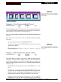
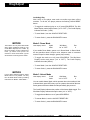
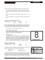
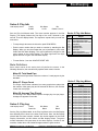
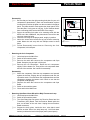
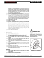
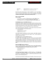
Machine Pays Up to 400 Coins
Balance Paid by Attendant
7
7
7
00000
$1 0 0 0 0 0
All Pays on Center Line Only - Only Highest Winner Paid
INSERT BILL
FACE UP
0
,,
,,
Upright Slot Machine
Model 40X Service Manual
With Details on 1995 Machines
© 1999 WMS Gaming Inc.
3401 N. California Avenue, Chicago, Illinois 60618
Phone (800)378-7741
February 1999
A-004336
Machine Pays Up to 400 Coins
Balance Paid by Attendant
7
7
7
00000
$1 0 0 0 0 0
All Pays on Center Line Only - Only Highest Winner
Paid
INSERT BILL
FACE UP
0
,,
,,
Upright
Slot
Machine
Model 40X
Service
Manual
With Details
on 1995
Machines
© 1999
WMS Gaming Inc.
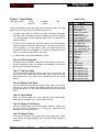
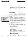
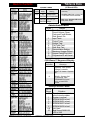
Contents
Model 40X Upright Slot Machine
Service Manual (A-004336)
Contents .........................................................................................(16-004337) ..1
Section 1. Setup & Software
Chapter 1. Setup........................................................................(16-004338) ...1-1
Procedure ...........................................................................................................................1-1
Lock Specifications .............................................................................................................1-5
Slot Machine Base Dimensions ..........................................................................................1-6
Gaming Device Dimensions................................................................................................1-7
Flammability Classification Weights....................................................................................1-7
Chapter 2. Diagnostic and Adjustment Software ...................(16-004339) ...2-1
Using Administration Mode .................................................................................................2-1
Administration Mode Displays.............................................................................................2-2
Series 0. Host Communications, Sound Volume, Demo, Cash and Credit Modes, Reel
Speed, Etc. ...................................................................................................................2-2
Series 1. Input Tests .........................................................................................................2-11
Series 2. Output Tests ......................................................................................................2-13
Series 3. Hopper Test .......................................................................................................2-15
Series 4. Paytable Test .....................................................................................................2-16
Series 5. Reel Strip Test ...................................................................................................2-17
Series 6. Denomination Settings.......................................................................................2-18
Series 7. Maximum Hopper Payout ..................................................................................2-20
Series 8. Hopper Partial Payout Limit ...............................................................................2-21
Series 9. Progressive ID and Level...................................................................................2-21
Series 10. Lamp Test ........................................................................................................2-23
Exit to Game Play Mode ...................................................................................................2-24
Chapter 3. Bookkeeping Mode.................................................(16-004340) ...3-1
Using Bookkeeping Mode ...................................................................................................3-1
Bookkeeping Mode Displays...............................................................................................3-2
Series 1. Coin Info ..............................................................................................................3-3
Series 2. Play Info ...............................................................................................................3-5
Series 3. Play Log ...............................................................................................................3-5
Series 4. Door Info ..............................................................................................................3-6
Series 5. Tilt Info .................................................................................................................3-7
Series 6. Bill Info .................................................................................................................3-7
Series 7. Bill Log .................................................................................................................3-8
Series 8. Bet Info ................................................................................................................3-8
Series 9. Cash Info .............................................................................................................3-9
Series 10. Line Info .............................................................................................................3-9
WMS Service Manual
16-004337—CONTENTS
S0/CH0
3
Contents
Series 11. Prog Info ..........................................................................................................3-10
Exit to Game Play Mode ...................................................................................................3-10
Section 2. Maintenance & Troubleshooting
Chapter 1. Periodic Maintenance.............................................(16-004341) ...1-1
Collection and Supply .........................................................................................................1-1
Bill Validator ........................................................................................................................1-1
CPU and Driver Boards, Card Cage ...................................................................................1-5
Glass ...................................................................................................................................1-7
Hopper ................................................................................................................................1-9
Lamps ...............................................................................................................................1-12
Power Distribution Unit .....................................................................................................1-13
Reels .................................................................................................................................1-13
Chapter 2. Software and Game Denomination Changes ....... (16-004342) ..2-1
Software Changes ..............................................................................................................2-1
Denomination Changes ......................................................................................................2-1
Card Cage Components .....................................................................................................2-1
EEPROM and RAM Interaction...........................................................................................2-1
Software Installation............................................................................................................2-2
Clearing the CPU Board RAM ............................................................................................2-3
How to Perform a Soft (Partial) RAM Clearance.................................................................2-5
How to Perform a Hard (Total) RAM Clearance .................................................................2-5
Changing the Denomination ...............................................................................................2-7
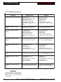
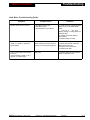
Chapter 3. Troubleshooting......................................................(16-004343) ...3-1
Tilt Codes ............................................................................................................................3-1
Candle Codes .....................................................................................................................3-2
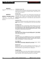
Button and Switch Troubleshooting Guide..........................................................................3-3
Candle Codes Troubleshooting Guide ................................................................................3-3
Communication Troubleshooting Guide..............................................................................3-3
CPU Board 7-Segment Display Troubleshooting Guide .....................................................3-4
CPU Board EEPROM Troubleshooting Guide ....................................................................3-5
CPU EPROM Troubleshooting Guide .................................................................................3-5
CPU Sound Jumpers ..........................................................................................................3-6
CPU Startup Sounds Troubleshooting Guide .....................................................................3-6
Dollar Bill Validator and Coin Mechanism Troubleshooting Guide .....................................3-7
Door Troubleshooting Guide ...............................................................................................3-8
Dotmation™ Troubleshooting Guide...................................................................................3-9
Dotmation+™ Troubleshooting Guide...............................................................................3-10
Hard Meter Troubleshooting Guide...................................................................................3-11
Hopper Troubleshooting Guide .........................................................................................3-12
Jurisdiction Jumper Troubleshooting Guide......................................................................3-13
Lamp Matrix Troubleshooting Guide .................................................................................3-14
Lamp Matrix................................................................................................................3-14
PGA Chip (Programmable Gate Array) Troubleshooting Guide .......................................3-15
Power Troubleshooting Guide ..........................................................................................3-15
Progressive Troubleshooting Guide..................................................................................3-16
Reel LED Display Board Troubleshooting Guide ..............................................................3-16
Reel Opto Troubleshooting Guide ....................................................................................3-17
Sound Troubleshooting Guide ..........................................................................................3-18
4
S0/CH0
16-004337—CONTENTS
WMS Service Manual
Contents
Static RAM Troubleshooting Guide...................................................................................3-19
Watchdog Timer Troubleshooting Guide ..........................................................................3-19
Section 3. Parts List
Chapter 1. Parts, Electronic .....................................................(16-004344) ...1-1
(In this chapter, parts appear in alphabetical order, under their assemblies.)
Chapter 2. Parts, Mechanical ...................................................(16-004345) ...2-1
(In this chapter, parts appear in alphabetical order, under their assemblies.)
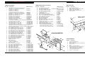
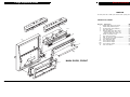
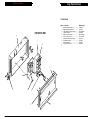
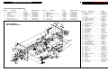
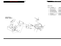
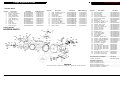
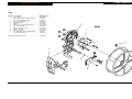
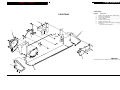
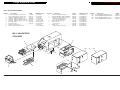
Chapter 3. Large Exploded Views............................................(16-004346) ...3-1
Section 4. Vendor Literature
Section 5. Service Bulletins
Section 6. Tables & Data for CPU System 1.5 VGDs..................(16-004349)
Administration Mode ..............................................................................................................1
Candle Codes ........................................................................................................................1
I/O Board LEDs ......................................................................................................................1
Startup Sound Codes .............................................................................................................1
Tilt Codes ...............................................................................................................................1
CPU Board 7-Segment Display..............................................................................................1
Lamp Matrix ...........................................................................................................................2
Programmed and Field Programmable Chip Summary .........................................................2
NOTICE
• Binder part number: 20-9896-02
• Divider tabs part number: 16-003639
• Part number for spine and cover inserts,
contents section (one shrink-wrapped
package): 16-004337
• Part number for entire manual: A-004336
WMS Service Manual
16-004337—CONTENTS
S0/CH0
5
Setup
Back to Contents
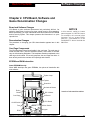
Chapter 1. Setup
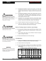
Power Requirements
Procedure
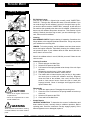
This chapter explains how to inspect and install a gaming device (GD). You'll
need these tools...
•11/32" NUT DRIVER
•PHILLIPS SCREWDRIVER
•ELECTRICAL OUTLET TESTER
Voltage
120 or 240 VAC
Line Freq 60 or 50 Hz
Current
4 amps max. at 120 VAC
2 amps max. at 240 VAC
•VOLTMETER
❑
1. Remove and set aside everything from the shipping container.
Inspect the cabinet exterior for damage.
❑
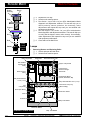
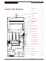
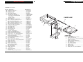
2. Unlock and open the front door.
Topbox Lamp
Topbox
Dotmation
Mechanical Meters
Reels
Chassis
Card Cage
On/Off Switch
Fuse
PDU
❑
I/O Board
CPU Board
Door Switch
Hopper
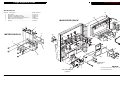
3. Check major components to assure that they mount securely to the
slot machine...
• HOPPER
• COIN ACCEPTOR
• BILL VALIDATOR (BV)
❑
Bill Validator
• UPPER/LOWER LAMP
• POWER DISTRIBUTION UNIT
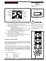
!
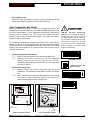
4. Base-Mounted Installation: Drill holes in the base to accommodate
cables and the drop door connection. To assure proper hole
placement, use drilling template 31-2230-00.
WMS Service Manual—Upright Slot
16-004338—SETUP
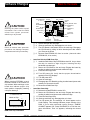
CAUTION
Don't install machines closer than six
inches (15.24 cm) apart.
S1/CH1
1-1
Setup
!
Back to Contents
CAUTION
CAUTION
If you install a player tracking unit (PTU)
in the slot machine: The PTU should be
certified by the CSA or by UL.
!
CAUTION
CAUTION
If you install a player tracking unit (PTU)
in the slot machine: The PTU ground
wire must be connected during use, and
reconnected after servicing.
NOTICE
❑
6. Base-Mounted Installation: Attach the slot machine base to the floor
with carriage bolts. Alternately, mount machines back to back on a
common base. Or, mount machines on separate bases, but bolt the
bases together from back to back.
❑
7. Operations with a Host System: Install host communication cables
according to recommendations of the communications system
provider. Connect the communication cables to the backplane.
❑
8. Attach the drop door connection to the drop door in the stand.
❑
9. Unlock the card cage. Check for damaged or loose connectors.
Don't force connectors! Close and lock the card cage.
Machines That Require Special Jurisdiction Jumper Settings...
❑
10. See the table I/O Board Jumper and DIP Switch Settings. If your
jurisdiction requires setting an I/O Board jumper, remove the I/O
Board.
❑
11. Find the SW1 jumper bank on the I/O Board. Connect the proper
jumper according to the table.
❑
12. Return the I/O Board to its slot in the card cage.
All Slot Machines...
❑
13. Check circuit boards to be sure that they mount securely to the
Backplane. (The Backplane Board is behind the card cage.)
❑
14. Close and lock the Card Cage Door.
❑
15. Use an outlet tester to measure your line voltage at the building
outlet. Verify that the line voltage is nominal for your area (110 or
220 volts AC).
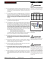
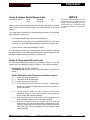
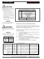
I/O Board Jumper and DIP Switch Settings
I/O JUMPERS. If you change a jumper
setting, you must perform a hard RAM
clearance. See the Maintenance and
Troubleshooting section.
1-2
5. Base-Mounted Installation: Attach the slot machine to the base with
supplied bolts and nuts. Hold the carriage bolts on the slot
machine's inside cabinet floor. Tighten the nuts from inside the drop
stand.
CAUTION
WARNING
BASE-MOUNTED INSTALLATION:
Mount machines back to back on a
common base. Or secure the base in
place. Otherwise the base can tip over,
causing injury or damage.
!
❑
S1/CH1
DIP Bank Jurisdiction
Standard
1
New Jersey
(Jumper
Missouri
Pad)
France
Delaware
Nevada
Progressive
2
Enabled
(Switch)
Disabled
16-004338—SETUP
8
Off
On
Off
On
Off
On
7
Off
Off
On
On
Off
Off
6
Off
Off
Off
Off
On
On
5
Off
Off
Off
Off
Off
Off
4
Off
Off
Off
Off
Off
Off
3
Off
Off
Off
Off
Off
Off
2
Off
Off
Off
Off
Off
Off
1
Off
Off
Off
Off
Off
Off
On
Off
Off
Off
Off
Off
Off
Off
Off
Off
Off
Off
Off
Off
Off
Off
WMS Service Manual—Upright Slot
Setup
Back to Contents
!
❑
16. Use an outlet tester to check for properly implemented ground, hot
and neutral outlet wiring. Only use a grounded AC outlet. If the outlet
checks okay, proceed. Otherwise, repair the outlet before
proceeding.
❑
17. Your slot machine may have a voltage range switch. You'll find this
switch on the connector side of the PDU. Never change this switch's
position with the line cord plugged in. Set the PDU voltage range
switch to match the local line voltage range. Setting this switch
incorrectly, or changing the switch position under power will cause
damage.
CAUTION
CAUTION
Take care when setting the hopper line
frequency switch. Setting this switch
incorrectly, or changing the switch
position under power will cause damage.
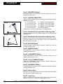
Hopper Probe Level
❑
18. Temporarily remove the hopper from the machine: Lift out the coin
tray and pull the hopper straight out.
❑
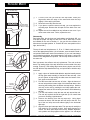
19. The hopper has a rotary type line frequency switch. Never adjust this
switch with the line cord plugged in. Check this switch's setting to
see that the factory setting matches the local line frequency. If not,
set the switch to match the local power line frequency. You'll find the
switch on the Hopper Control Board. Access the switch by sliding
out the hopper. Look at the Hopper Control Board through the
window, beneath and beside the hopper bowl. Notice the arrow on
the switch face. This arrow points to either "110" or "220." (These
switch labels have nothing to do with line voltage.)
• In 60 Hz areas, the arrow should point to "110."
• In 50 Hz areas, the arrow should point to "220."
To adjust the switch, insert a small screwdriver in the slot atop the
switch. Turn the screwdriver to select the hopper line frequency.
❑
20. Plug the female end of the line cord into the slot machine's Power
Distribution Unit. You'll find the Power Distribution Unit on the lower
left, inside cabinet wall. Drop the line cord through the base and out
the lower hole.
❑
21. Check the slot machine for loose or missing hardware. Missing
hardware may have fallen into the hopper. Clean it out of there
before the hopper jams! Replace the hardware.
❑
22. Check the hopper: Before filling the hopper with coins, remove dust,
dirt, loose hardware and other foreign matter.
❑
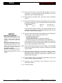
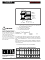
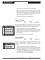
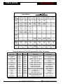
23. See the table Hopper Probe Level. Adjust the hopper coin-level
probe. Move the probe to a higher hole if the hopper will hold more
coins. Move the probe to a lower hole if the hopper will hold fewer
coins.
❑
24. Return the hopper to the machine. Fill the hopper with coins of the
proper denomination. See the table Hopper Probe Level. The table
approximates the optimum number of coins for each coin-level probe
hole.
WMS Service Manual—Upright Slot
16-004338—SETUP
Probe
Hole
5
4
3
2
1
5
4
2
U.S. $1
1,080
710
680
530
330
25¢
4,080
3,030
2,410
2,150
1,730
5¢
4,820
3,600
2,850
2,560
1,900
3
1
Probe Holes
Back view of hopper, showing
probe holes.
!
CAUTION
CAUTION
Plugging a 120V slot machine into a
240V line will damage the slot machine.
!
CAUTION
WARNING
Install Electrical Outlets For GDs near
the equipment. The outlets must be
easily accessible. Otherwise, you may
not be able to remove GD power.
Working on a GD with power applied
may expose you to hazardous line
voltage. Switching off the PDU doesn’t
remove power from the interior of the
GD. To eliminate this power, you must
unplug the GD.
S1/CH1
1-3
Setup
Back to Contents
❑
25. Install a typical coin of the proper denomination in the coin
comparator. If you need to adjust the coin mechanism, refer to the
Maintenance and Troubleshooting section.
❑
26. Record starting cumulative totals. (Copy them off the mechanical
meters.)
❑
27. Be sure that boards and connectors seat properly. Check card cage
boards and connectors on door, chassis and cabinet boards. Don't
forget these connectors...
• BILL VALIDATOR
• PDU
• REELS
• BACKPLANE
• METERS
• DOOR SWITCHBOX
• INLINE CONNECTORS
Also check blind mating connectors: If the hopper operates, then its
connector mates properly. If you hear the bong after power up, then
the speaker connector mates properly.
❑
NOTICE
OTHER SETUP PROCEDURES...
• Denomination Adjustments: See the
Maintenance and Troubleshooting
section of this manual. Also see
Chapter 2, Diagnostic and Adjustment
Software.
• Reel Strip Installation: Follow the
procedure in the Maintenance and
Troubleshooting section of this
manual. Run the Reel Strip Test
described in Chapter 2, Diagnostic
and Adjustment Software.
• Software Installation: Procedures
appear in the Maintenance and
Troubleshooting section of this
manual.
1-4
S1/CH1
28. Turn on the slot machine at the Power Distribution Unit (PDU) on/off
switch. During a normal startup, these events occur...
• Slot machine lamps come on
• The reels spin and home
• The bill validator whines as it undergoes a self test
• The machine bongs once, indicating a nominal initialization
If the lamps don't light and you don't hear the bong: Did you plug the
slot machine into an active, unswitched AC outlet? If you hear more
than one bong, troubleshoot the slot machine.
NOTE: If any I/O DIP switch settings have been changed, a full Hard RAM
Clear must be performed. Refer to Section 2, Chapter 2 for the RAM
Clear procedure.
❑
29. Enter Administration Mode and set the machine protocol address.
(Machine Protocol Address is Series 0, Sequence 1 of
Administration Mode.) Also set the option sound, credit mode, reels,
attract mode, bills and limits.
❑
30. Run a diagnostic check of the software and hardware. Use the slot
machine’s built-in, diagnostic software.
❑
31. Install the locks specified by your jurisdiction. (See Lock
Specification Table.)
❑
32. Lock the front door.
16-004338—SETUP
WMS Service Manual—Upright Slot
Setup
Back to Contents
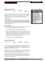
SPECIFICATIONS FOR STANDARD LOCKS (INCHES)
Dimensions, Cam Mounting Hole: Diameter 0.28" x 0.22"
Barrel
Double D
Rotation
Door
Length
Hole Size
to Unlock
Stacker
5/8"
0.76" x 0.64"
CCW
Logic
5/8"
0.76" x 0.64"
CW or CCW
Main
5/8"
0.76" x 0.64"
CCW
Stacker Extract. Tool
5/8"
0.76" x 0.64"
CCW
Barrel
Double D
Rotation
Lock/Switch
Length
Hole Size
to Unlock
NJ Extra Extract. Lk.
5/8"
0.76" x 0.64"
CCW
Cam must rotate in the same direction as the lock.
Opposite of Bill Stacker
NJ Extra Stacker Dr. Lk. 5/8"
0.76" x 0.64"
Door Lock
Barrel Lock Spacers
P/N 02-4916-01: 1/16"
P/N 02-4916-02: 1/8"
P/N 02-4916-03: 3/16"
P/N 02-4916-04: 1/4"
SPECIFICATIONS FOR STANDARD LOCKS (METRIC)
Dimensions, Cam Mounting Hole: Diameter .71cm x .56cm
Barrel
Double D
Rotation
Door
Length
Hole Size
to Unlock
Stacker
1.59cm
.19cm x .16cm
CCW
Logic
1.59cm
.19cm x .16cm
CW or CCW
Main
1.59cm
.19cm x .16cm
CCW
Stacker Extract. Tool 1.59cm
.19cm x .16cm
CCW
Barrel
Double D
Rotation
Lock/Switch
Length
Hole Size
to Unlock
NJ Extra Extract. Lk. 1.59cm
.19cm x .16cm
CCW
Cam must rotate in the same direction as the lock.
NJ Extra Stakr. Dr. Lk. 1.59cm
.19cm x .16cm
Opposite of Bill Stacker
Door Lock
Barrel Lock Spacers
P/N 02-4916-01: .16cm
P/N 02-4916-02: .32cm
P/N 02-4916-03: .48cm
P/N 02-4916-04: .64cm
WMS Service Manual—Upright Slot
16-004338—SETUP
S1/CH1
1-5
Setup
Back to Contents
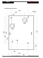
Slot Machine Base Dimensions
1-6
S1/CH1
16-004338—SETUP
WMS Service Manual—Upright Slot
Setup
Back to Contents
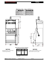
Wide Body Slot – Model 40S Series
9'' Topbox
9'' Topbox w/Cardreader
16'' Topbox
16'' Topbox w/Cardreader
Bonnet Topbox
Bonnet Topbox w/Cardreader
9.88 (25.35)
12.25 (31.12)
15.97 (40.56)
18.34 (46.58)
15.97 (40.56)
18.34 (46.58)
15.88 (40.34)
18.25 (46.36)
21.40 (54.36)
23.77 (60.38)
21.20 (53.85)
23.57 (59.87)
Overall
Height
Topbox
Height
30.25
(76.84)
19.66 (49.94)
Top of
Button
Panel
(53.98)
15.88
(40.34)
20.89
(53.06)
(8.43)
Flammability Classification Weights*
NOTICE
Measurements are in inches and in
centimeters (parentheses).
Category
Combustible
Total
Lbs.
Kg.
8.58
3.89
241.14
109.38
NOTICE
To allow opening of the Bill Door, space
games at least 6” (15.24 cm) apart.
*Including metal topbox, but without
card reader
WMS Service Manual—Upright Slot
16-004338—SETUP
S1/CH1
1-7
Diag/Adjust
Back to Contents
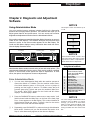
Chapter 2. Diagnostic and Adjustment
Software
NOTICE
Using Administration Mode
Your slot machine's game software includes facilities for diagnosing
problems and verifying feature operation. This software also helps you to
adjust game features and performance. You can access slot machine
diagnostic and adjustment functions from the Administration Mode.
This chapter covers slot software up to
v. 5.09.
Test Series
Slot machine software presents Administration Mode information as numeric
codes on the LED displays. The software arranges the tests and setup
features in series. A test series number appears on the Bet Display. The
Credit and Win Meter displays convey information about each test series.
See the display illustration below.
Test Sequence
Test or Mode
Credit Display
Win Meter Display
Bet Display
NOTICE
$1
CREDIT
WIN METER
BET
Administration Mode contains test
and setup series. Most series contain
sequences of tests or adjustments.
Some series have no sequences.
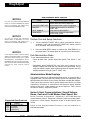
Administration Mode
Administration Mode contains several series of test and setup options. (The
Administration Mode table lists the series.) Each series contains numbered
options. In some series, these options are tests or adjustments. In other
series, the options are sequences of tests or adjustments.
Subject
Series
0
Host Communications,
Sound Volume; Demo,
Cash and Credit Modes,
Reel Speed, Etc.
1
Input Tests
2
Output Tests
3
Hopper Test
4
Pay Table Test
5
Reel Strip Test
6
Denomination Setting
7
Maximum Hopper Payout
8
Hopper Partial Pay Limit
9
Progressive ID and Level
10
Lamp Test and Custom
Features Tests
Enter Administration Mode
❑
1. You can enter Administration Mode while the machine operates in
Game-Over Mode or Tilt Mode. (The slot machine enters GameOver Mode between games. In this mode, no bet or jackpot is
pending and the hopper is inactive. Tilt Mode means that a tilt
prevents game play.) Unlock and open the machine's Main Door.
The words, "door oPEn" appear on the Credit and Win Meter
displays. The Bet Display is blank.
❑
2. Press the DIAGNOSTIC button to select a test or setup series. You'll
find this button inside the Main Door, on the front of the Card Cage
Door. A zero appears on the Bet Display. This number identifies an
Administration Mode test series. Typically, data for that series
appears in the Credit and Win Meter displays.
❑
3. Repeatedly press DIAGNOSTIC to advance through Administration
Mode series. Continue until you find the desired test series. As in
Step 2, series data usually appears on the other two displays.
WMS Service Manual—Slot Machine
NOTICE
You can't change Administration Mode
selections from Tilt Mode. To change
settings, you must be in Game-Over
Mode. To enter Game-Over Mode, open
and close the Main Door. Opening and
closing the Main Door also clears most
tilts.
16-004339—DIAGNOSTICS/ADJUSTMENTS
S1/CH2
2-1
Diag/Adjust
Back to Contents
Administration Mode Controls
NOTICE
Switch
• DIAGNOSTIC
You can use either the SPIN REELS
button or the SLOT HANDLE to initiate
tests. For simplicity, this chapter only
mentions the SPIN REELS button.
• JACKPOT RESET KEY
• MAX BET
• SLOT HANDLE
• SPIN REELS
Administration Mode Function
Enters and advances through Administration Mode test series, sequences
Selects tests within a series or sequence
Usually has same effect as JACKPOT
RESET KEY
Same effect as SPIN REELS
Initiates tests (except for input tests);
selects setup options
NOTICE
You can use either the JACKPOT
RESET KEY or MAX BET to select
tests. For simplicity, this chapter only
mentions the JACKPOT RESET KEY.
NOTICE
In this manual, switch or button names
appear in CAPITAL letters. For example,
this manual often instructs you to “press
DIAGNOSTIC.” DIAGNOSTIC is the
DIAGNOSTIC button behind the Main
Door. See the table Administration Mode
Controls for other common switch
names.
Perform Test and Setup Functions
❑
1. Turn the JACKPOT RESET KEY to select a test within a series or
sequence. You'll find the JACKPOT RESET KEY switch near the
SLOT HANDLE. Insert and turn the key.
❑
2. Press the SPIN REELS button to initiate a test. SPIN REELS is on
the player panel. The button lights up to remind you to start the test.
Exit Administration Mode
To exit Administration Mode, either...
• Close the Main Door (except during Door Switch Test, Series 1, Test
13).
• Repeatedly press DIAGNOSTIC until "door open" appears on the
display. Displays that read this way indicate Door-Open Mode, one of
many slot machine states. When a game reports a tilt condition, the LED
displays indicate the tilt type ("coinJ," "HPrE," etc).
Administration Mode Displays
This chapter introduces an Administration Mode series or sequence with a
highlighted table. (A test series may contain several test sequences.) Each
table presents initial values for the Credit, Win Meter and Max Bet displays.
These values document the way a typical display reads before you make
adjustments. Sometimes, a series and its first sequence display identical
values. In that case, a table appears only at the sequence. Take a look at
the table for Series 0, Sequence 1 below...
Series 0. Host Communications, Sound Volume;
Demo, Cash and Credit Modes, Reel Speed, Etc.
Supported Host Protocols
Credit
Display
NONE
SAS
SdS
ACP
2-2
Protocol
No Host Communication
IGT System
Bally System
WMS Protocol
S1/CH2
Series 0 includes 10 sequences... Sequences 1 and 2 deal with host
communications protocol. Sequences 3 through 6 affect the sound system.
Sequence 7 is Reel Speed. Sequences 9 and 10 enable special game
modes.
Series 0 Host Communications Protocol is the first sequence in
Administration Mode.
16-004339—DIAGNOSTICS/ADJUSTMENTS
WMS Service Manual—Slot Machine
Diag/Adjust
Back to Contents
NOTICE
Change
Cash/
Credit
Bet
One
Spin Reels
Max Bet Spin
Older machines use a CALL ATTENDANT button, instead of the CHANGE
button shown.
Player Panel Buttons
Sequence 1. Host Communications Protocol
Initial Display Values:
Credit
NONE
Win Meter
ON
Bet
0
The Credit Display provides a mnemonic for a host communications protocol.
The Win Meter Display indicates whether this mnemonic represents the
selected protocol. "On" identifies the selected protocol.
Your slot machine supports several protocols. See the table Supported Host
Protocols.
Slot machines that use protocols with configurable addressing display
Sequence 1.
• To view each protocol, turn the JACKPOT RESET KEY.
• To select a protocol, press SPIN REELS. If you aren’t using a host
system, select “NONE.”
• To save settings, skip Sequence 2 and enter Sequence 3, press the
DIAGNOSTIC button.
NOTICE
You can exit Administration Mode and
save changes anytime by closing the
Main Door.
Sequence 2. Machine Protocol Address (SAS)
Initial Display Values:
Credit
Addr
Win Meter
3-Digit No.
Bet
0
The Credit Display contains the expression, "Addr," the abbreviation for
"Address." The Win Meter Display indicates the slot machine's
communication address. If you haven't set the address yet, three zeros
appear. You can vary this level from 0 to 127. The flashing digit indicates the
first value to set.
• To change the flashing digit value, press SPIN REELS one or more
times.
• To advance to the next digit, turn the JACKPOT RESET KEY. With each
turn of the key, the flashing digit sequentially advances from right to left.
Suppose that the flashing digit is the leftmost one: Return to the
rightmost digit by turning the JACKPOT RESET KEY one more time.
• To delete a protocol and replace it with another one, turn the JACKPOT
RESET KEY. Turn the key again, as necessary, until you locate the
WMS Service Manual—Slot Machine
16-004339—DIAGNOSTICS/ADJUSTMENTS
S1/CH2
2-3
Diag/Adjust
Back to Contents
desired new protocol. Set values at the new protocol, as above. The
new protocol now replaces the previously set protocol.
• To save settings and enter Sequence 3, press the DIAGNOSTIC button.
Manual Sound System
Some game software includes a manual user interface for sound volume
settings. Other game software incorporates an automated user interface.
Your game software employs either interface, but not both. The interface
type affects Series 0, sequences 3, 4 and 5. Your machine has either the
manual or the automated version of these three sequences. This manual
describes both versions. Here’s how the manual sound user interface
behaves...
Sequence 3. Normal Sound Volume (Manual)
Initial Display Values:
Credit
Snd 1
Win Meter
3-Digit No.
Bet
0
Normal Sound Volume controls regular game sounds during normal game
operation. (For example, credit bet and coin-in sounds, and most smaller
awards tunes.) The Win Meter Display indicates the slot machine's sound
volume setting. You can vary this level from 0 to 255. The flashing digit
indicates the first value to set. During Sequence 3, you can toggle the sound
on or off with the lit MAX BET button. Pressing MAX BET, you hear the
credit/bet sound at the new volume level. Use this sound to determine the
effect of your adjustment.
• To change the flashing digit value, press SPIN REELS one or more
times.
• To advance to the next digit, turn the JACKPOT RESET KEY. With each
turn of the key, the flashing digit sequentially advances from right to left.
Suppose that the flashing digit is the leftmost one: Return to the
rightmost digit by turning the JACKPOT RESET KEY one more time.
• To save settings and enter Sequence 4, press the DIAGNOSTIC button.
Sequence 4. Large Hit Sound Volume (Manual)
Initial Display Values:
Credit
Snd 2
Win Meter
3-Digit No.
Bet
0
Large Hit Sound Volume controls volume during a large award payout. (How
large is “large”? “Large” is game specific, but a rule of thumb applies:
Usually a large hit exceeds 50 credits.) Typically, Large Hit Sound Volume is
much louder than normal volume. Use Large Hit Sound Volume to draw
attention to the machine during large wins. The Win Meter Display indicates
the slot machine's sound volume setting. You can vary this level from 0 to
2-4
S1/CH2
16-004339—DIAGNOSTICS/ADJUSTMENTS
WMS Service Manual—Slot Machine
Diag/Adjust
Back to Contents
255. The flashing digit indicates the first value to set. You can toggle the
sound on or off with the lit MAX BET button. Pressing MAX BET, you hear
the large award tune at the new volume level. Use this sound to determine
the effect of your adjustment.
• To change the flashing digit value, press SPIN REELS one or more
times.
• To advance to the next digit, turn the JACKPOT RESET KEY. With each
turn of the key, the flashing digit sequentially advances from right to left.
Suppose that the flashing digit is the leftmost one: Return to the
rightmost digit by turning the JACKPOT RESET KEY one more time.
• To save settings and enter Sequence 5, press the DIAGNOSTIC button.
Sequence 5. Top Award Sound Volume (Manual)
Initial Display Values:
Credit
Snd 3
Win Meter
3-Digit No.
Bet
0
Top Award Sound Volume controls volume when a player hits the top award.
(Typically, this award is a jackpot.) Usually operators set this volume nearly
wide open to draw attention to the machine. The Win Meter Display
indicates the slot machine's sound volume setting. You can vary this level
from 0 to 255. The flashing digit indicates the first value to set. You can
toggle the sound on or off with the lit MAX BET button. Pressing MAX BET,
you hear the jackpot tune at the new volume level. Use this sound to
determine the effect of your adjustment.
• To change the flashing digit value, press SPIN REELS one or more
times.
• To advance to the next digit, turn the JACKPOT RESET KEY. With each
turn of the key, the flashing digit sequentially advances from right to left.
Suppose that the flashing digit is the leftmost one: Return to the
rightmost digit by turning the JACKPOT RESET KEY one more time.
• To save settings and enter Sequence 6, press the DIAGNOSTIC button.
Automated Sound System
Some game software includes an automated user interface for sound
volume settings. This automated interface operates differently than the
manual interface already described. Automated versions of Sequences 3, 4
and 5 replace manual versions that we’ve described above. Here’s how the
automated sound user interface behaves...
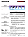
Dotmation Display. On Dotmation games (such as Winning Streak ),
settings and instructions appear in the Dotmation screen. (See the
illustrations Automatic Sound Screen 1 and Automatic Sound Screen 2.)
Instructions also appear on LED displays.
WMS Service Manual—Slot Machine
16-004339—DIAGNOSTICS/ADJUSTMENTS
S1/CH2
2-5
Diag/Adjust
Back to Contents
Automatic Sound Screen 1
Sequence 3. Normal Sound Volume (Automated)
Initial Display Values:
VOLUME SETTINGS
Credit
Snd 1
Win Meter
3-Digit No.
Bet
0
NORMAL VOL: 03
SPIN REELS LOWERS VOLUME
MAX BET RAISES VOLUME
BET 1 MUTES SOUND
Automatic Sound Screen 2
VOLUME SETTINGS
NORMAL VOL: 09
Normal Sound Volume controls regular game sounds during normal game
operation. (For example, credit bet and coin-in sounds, reel spin and most
smaller awards tunes.) The Win Meter Display indicates the slot machine's
sound volume setting. You can vary this level from 0 to 63.
Auto Settings. The automated sound system includes “auto” settings for
Snd 2 and Snd 3. These settings default to “on” for most games. (The
default is “off” for Delaware games, due to the different volume settings in
Delaware.) In “Auto,” the volume for any sound sequence is double that of
the previous sequence. You must only change Snd 1 to make the game
quieter or louder. This feature simplifies game setup.
Ordinarily, you can’t set the value of Snd 3 lower than Snd 2. Similarly, you
usually can’t set Snd 2 to a lower value than Snd 1. What if you raise Snd 1
above the Snd 2 or Snd 3 value? Then Snd 2 and Snd 3 automatically set to
the value of Snd 1.
FEATURE VOL: AUTO
JACKPOT VOL: AUTO
BET 1 MUTES SOUND
• To play or mute the sound, press BET ONE. (BET ONE toggles the
sound on and off.) Pressing BET ONE, you hear the credit/bet sound at
the new volume level. Use this sound to determine the effect of your
adjustment.
NOTICE
• To reduce sound volume, press SPIN REELS.
The Automated Sound Value Range is 0
to 63, instead of 0 to 255. Sound level
63 in the automated sound system
equals level 255 in the manual system.
The automated system’s volume 25
(Snd 1) equals the manual system’s
starting volume 30.
• To raise sound volume, press MAX BET SPIN.
• To turn “AUTO” settings on or off, press CASH and either SPIN or MAX
BET. (Setting toggles between “auto on” and “auto off” functions.)
• To reduce Snd 2 or Snd 3 below Snd 1, turn JACKPOT RESET KEY.
Simultaneously press MAX BET SPIN.
• To move the arrow in Sound Screen 2, press DIAGNOSTIC. (See the
illustration Automatic Sound Screen 2.)
• To save settings and enter Sequence 4, press the DIAGNOSTIC button.
Sequence 4. Feature Sound Volume (Automated)
Initial Display Values:
Credit
Snd 2
Win Meter
3-Digit No.
Bet
0
Feature Sound Volume controls volume during a large award payout. (How
large is “large”? “Large” is game specific, but a rule of thumb applies:
Usually feature sound exceeds 50 credits.) Typically, Feature Sound Volume
is much louder than normal volume. Use Feature Sound Volume to draw
attention to the machine during large wins. (For example, “feature” game
2-6
S1/CH2
16-004339—DIAGNOSTICS/ADJUSTMENTS
WMS Service Manual—Slot Machine
Diag/Adjust
Back to Contents
sounds, such as the Winning Streak Bonus Round.) The Win Meter Display
indicates the slot machine's sound volume setting. You can vary this level
from 0 to 63.
Auto Settings. The automated sound system includes “auto” settings for
Snd 2 and Snd 3. These settings default to “on” for most games. (The default
is “off” for Delaware games, due to the different volume settings in
Delaware.) In “Auto,” the volume for any sound sequence is double that of
the previous sequence. You must only change Snd 1 to make the game
quieter or louder. This feature simplifies game setup.
Ordinarily, you can’t set the value of Snd 3 lower than Snd 2. Similarly, you
usually can’t set Snd 2 to a lower value than Snd 1. What if you raise Snd 1
above the Snd 2 or Snd 3 value? Then Snd 2 and Snd 3 automatically set to
the value of Snd 1.
• To play or mute the sound, press BET ONE. (BET ONE toggles the
sound on and off.) Pressing BET ONE, you hear the large award tune at
the new volume level. Use this sound to determine the effect of your
adjustment.
• To reduce sound volume, press SPIN REELS.
• To raise sound volume, press MAX BET SPIN.
• To turn “AUTO” settings on or off, press CASH and either SPIN or MAX
BET. (Setting toggles between “auto on” and “auto off” functions.)
• To reduce Snd 2 or Snd 3 below Snd 1, turn JACKPOT RESET KEY.
Simultaneously press MAX BET SPIN.
• To move the arrow in Sound Screen 2, press DIAGNOSTIC. (See the
illustration Automatic Sound Screen 2.)
• To save settings and enter Sequence 4, press the DIAGNOSTIC button.
• To change the flashing digit value, press SPIN REELS one or more
times.
• To advance to the next digit, turn the JACKPOT RESET KEY. With each
turn of the key, the flashing digit sequentially advances from right to left.
Suppose that the flashing digit is the leftmost one: Return to the
rightmost digit by turning the JACKPOT RESET KEY one more time.
• To save settings and enter Sequence 5, press the DIAGNOSTIC button.
Sequence 5. Top Award Sound Volume (Automated)
Initial Display Values:
Credit
Snd 3
Win Meter
3-Digit No.
Bet
0
Top Award Sound Volume controls volume when a player hits the top award.
(Typically, this award is a jackpot.) Usually operators set this volume nearly
WMS Service Manual—Slot Machine
16-004339—DIAGNOSTICS/ADJUSTMENTS
S1/CH2
2-7
Diag/Adjust
Back to Contents
wide open to draw attention to the machine. The Win Meter Display
indicates the slot machine's sound volume setting. You can vary this level
from 0 to 63.
Auto Settings. The automated sound system includes “auto” settings for
Snd 2 and Snd 3. These settings default to “on” for most games. (The
default is “off” for Delaware games, due to the different volume settings in
Delaware.) In “Auto,” the volume for any sound sequence is double that of
the previous sequence. You must only change Snd 1 to make the game
quieter or louder. This feature simplifies game setup.
Ordinarily, you can’t set the value of Snd 3 lower than Snd 2. Similarly, you
usually can’t set Snd 2 to a lower value than Snd 1. What if you raise Snd 1
above the Snd 2 or Snd 3 value? Then Snd 2 and Snd 3 automatically set to
the value of Snd 1.
• To play or mute the sound, press BET ONE. (BET ONE toggles the
sound on and off.) Pressing BET ONE, you hear the jackpot tune at the
new volume level. Use this sound to determine the effect of your
adjustment.
• To reduce sound volume, press SPIN REELS.
• To raise sound volume, press MAX BET SPIN.
• To turn “AUTO” settings on or off, press CASH and either SPIN or MAX
BET. (Setting toggles between “auto on” and “auto off” functions.)
• To reduce Snd 2 or Snd 3 below Snd 1, turn JACKPOT RESET KEY.
Simultaneously press MAX BET SPIN.
• To move the arrow in Sound Screen 2, press DIAGNOSTIC. (See the
illustration Automatic Sound Screen 2.)
• To save settings and enter Sequence 6, press the DIAGNOSTIC button.
Sequence 6. Jackpot Loop
Initial Display Values:
NOTICE
Some jurisdictions require that the
jackpot tune must play until the
attendant resets the machine. Soldered
jumpers on the I/O Board configure the
machine for these jurisdictions. On
boards configured that way, Sequence 6
only permits you to view the loop status.
Also, you can’t select this option. A dark
Spin Reels Lamp indicates this
condition.
2-8
S1/CH2
Credit
LooP
Win Meter
inFin
Bet
0
Choose the number of times that the jackpot tune plays after a jackpot win.
Select any number of plays, from 1 to 254. Select 255 to put the machine
into Infinite Loop Mode, the default setting. In Infinite Loop Mode, the jackpot
tune repeats until the attendant resets the jackpot.
• To change the flashing digit value, press SPIN REELS one or more
times.
• To advance to the next digit, turn the JACKPOT RESET KEY. With each
turn of the key, the flashing digit sequentially advances from right to left.
16-004339—DIAGNOSTICS/ADJUSTMENTS
WMS Service Manual—Slot Machine
Diag/Adjust
Back to Contents
Suppose that the flashing digit is the leftmost one: Return to the
rightmost digit by turning the JACKPOT RESET KEY one more time.
• To save settings and enter Sequence 7, press the DIAGNOSTIC button.
Reel Speed Adjustment
Sequence 7. Reel Speed
Initial Display Values:
Credit
SpEEd
Win Meter
nnEd
Bet
0
Credit
Display
Slo
nnEd
Reel Speed
Slow
Medium
Select the speed at which the reels spin. The Credit Display indicates the
reel “SPEED” setting. The Win Meter Display indicates the selected speed.
• To select a different speed, press SPIN REELS. Options appear on the
Reel Speed Adjustment Table.
• To save settings and skip Sequence 8 and enter Series 1, press the
DIAGNOSTIC button.
• To save settings and enter Sequence 8, turn the JACKPOT RESET
KEY.
Sequence 8. Special Operation Modes
Initial Display Values:
Credit
crEd
Win Meter
“on” or "OFF"
Bet
0
Operation modes determine much of slot machine behavior and
performance. Your slot machine includes a number of these modes. Game
Mode, Game-Over Mode and Administration Mode are three familiar modes.
Software prohibits you from directly modifying Game Mode. But as this
chapter illustrates, Administration Mode permits a broad variety of user
adjustments. Other modes affect the slot machine in a much narrower
sense. Sequence 8 includes three such modes...
• Mode 1. Cash and Credit Play
• Mode 2. Demo Mode
• Mode 3. Attract Mode
Mode 1. Credit and Cash Play
Initial Display Values:
Credit
crEd
Win Meter
“on” or "OFF"
Bet
0
Cash or Credit Play
Disable "crEd" to permit the player to choose cash or credit play. In
credit play, winnings accumulate as credits on the machine. In cash
play, the slot machine immediately dispenses winnings. With CASH OR
CREDIT off, if the player presses CASH/CREDIT, it lights. The lit button
indicates Credit Mode.
WMS Service Manual—Slot Machine
16-004339—DIAGNOSTICS/ADJUSTMENTS
S1/CH2
2-9
Diag/Adjust
Back to Contents
Credit-Only Play
With "crEd" on, the player must cash out credits to get them off the
machine. To do this, the player presses the flashing CASH/CREDIT
button.
• To toggle the credit-only play on or off, press SPIN REELS. The Win
Meter Display tracks feature status ("on" or "OFF”). The Credit Display
indicates the mode ("crEd").
• To enter Mode 2, turn the JACKPOT RESET KEY.
• To enter Series 1, press the DIAGNOSTIC button.
NOTICE
Mode 2. Demo Mode
The machine can only enter Demo Mode
when certain conditions prevail: (1) The
Credit Meter displays zero credits. (2)
No bet is pending. (3) The machine isn’t
tilted. (4) Game rules permit the
machine to enter Demo Mode. (5) The
slot machine isn’t storing bonus credits.
Initial Display Values:
Credit
dEno
Win Meter
“on” or "OFF"
Bet
0
If you enable Demo Mode, games run in Demo Mode. In Demo Mode,
the slot machine doesn't require coins, dispense cash or increment
meters. Except for these changes, games play normally.
• To toggle the mode on or off, press SPIN REELS. The Win Meter
Display tracks mode status (“on” or "OFF”). The Credit Display
indicates the mode ("dEno").
• To enter Mode 3, turn the JACKPOT RESET KEY.
• To enter Series 1, press the DIAGNOSTIC button.
NOTICE
In some game software versions, Attract
Mode sound is on by default. You may
turn off Attract Mode sound by following
instructions at “Mode 3. Attract Mode.”
Mode 3. Attract Mode
Initial Display Values:
Credit
AtrAc
Win Meter
“on” or "OFF"
Bet
0
You can enable Attract Mode, which operates when the machine is idle.
In Attract Mode, panel LEDs may cycle in a pattern after a brief idle time.
Some games with Attract Mode sounds periodically play a sound.
The Credit Display indicates the position of the Attract Mode toggle. The
Win Meter Display indicates the option state (“on” or "OFF”).
• To toggle Attract Mode on or off, press SPIN REELS .
• To reenter Mode 1, turn the JACKPOT RESET KEY.
• To enter Series 1, press the DIAGNOSTIC button.
2-10
S1/CH2
16-004339—DIAGNOSTICS/ADJUSTMENTS
WMS Service Manual—Slot Machine
Diag/Adjust
Back to Contents
Series 1. Input Tests
Initial Display Values:
Input Tests
Credit
3-Digit No.
Win Meter
(Blank)
Bet
1
In the Credit Display, the left two digits represent the test number. The right
digit is the current logic level of the selected input (0 or 1).
• To select a test, locate its number on the Input Tests table. Repeatedly
press MAX BET until display numbers correspond to the table. (Instead,
you may repeatedly turn the JACKPOT RESET KEY. But MAX BET is
easier to actuate.)
• To test an input, activate the input and observe logic level changes.
Inputs are either mechanical or opto switches. The optos are below the
coin comparator. (Your slot machine uses a Coin Mechanisms Coin
Comparitor® brand coin comparator.) To activate a mechanical switch,
close it. To activate an opto, block it with a coin.
• To enter Series 2, press the DIAGNOSTIC button.
Test 10. Coin Comparator
Dismount the coin comparator. Watch the Credit Display and drop a coin
into the comparator. As the coin passes the comparator metal sensor,
the zero logic level digit becomes one.
Test 11. Top Coin Opto
This test checks the response of the top opto. Drop a coin into the coin
entry. As the coin breaks the detector beam, the zero logic level digit
should become one. Any other result indicates that the opto needs
service.
Test
10
11
12
13
14
15
16
17
18
19
20
21
22
23
25
26
27
28
29
30
31
40
41
42
70
71
72
73
74
75
Subject
Coin Comparator
Top Coin Opto
Bottom Coin Opto
Door Switch
Hopper Coin Sensor
Hopper Probe
SPIN REELS button
ATTENDANT KEY
SLOT HANDLE, top sw
SLOT HANDLE, btm sw
BET ONE button
MAX BET button
CASH/CREDIT button
CALL ATTENDANT btn
DIAGNOSTIC button
Stacker Door
Logic Door
Bill Door
Drop Door
b Serv
Hood
Reel #1 Opto
Reel #2 Opto
Reel #3 Opto
Game-Specific Input
Game-Specific Input
Game-Specific Input
Game-Specific Input
Game-Specific Input
Game-Specific Input
Test 12. Bottom Coin Opto
This test checks the response of the bottom opto. Drop a coin into the
coin entry. As the coin breaks the detector beam, the zero logic level
digit should become one. Any other result indicates that the opto needs
service.
Test 13. Door Switch
When you close the Main Door, a zero appears on the Credit Display.
When you open the Main Door, a one replaces the zero.
Test 14. Hopper Coin Sensor
Press the spring-loaded lever atop the hopper escalator. Initially zero,
the logic level digit changes to one. During play, dispensed coins
actuate the lever, closing contacts.
Test 15. Hopper Probe
Use a coin to ground the top hopper probe to the hopper bowl. Initially
zero, the logic level digit changes to one. A grounded probe indicates a
full hopper.
WMS Service Manual—Slot Machine
16-004339—DIAGNOSTICS/ADJUSTMENTS
S1/CH2
2-11
Diag/Adjust
Back to Contents
Test 16. SPIN REELS Button
Press SPIN REELS to test the button's operation. Initially zero, the logic
level digit changes to one.
Test 17. JACKPOT RESET KEY
Test 18
1
o
Test the JACKPOT RESET KEY: Turn the key in the indicated direction,
following these steps...
❑ 1. Turn the key CW:
17 1 appears on the Credit Display.
❑ 2. Turn the key CCW:
17 0 appears on the Credit Display.
❑ 3. Turn the key CW:
17 1 appears on the Credit Display.
❑ 4. Turn the key CCW:
17 0 appears on the Credit Display.
❑ 5. Turn the key CW:
18 (next test) appears.
(CW stands for clockwise. CCW stands for counterclockwise.)
Test 18. Slot Handle (Not applicable to slant top slots)
Pull the slot handle to test its top switch. Initially zero, the logic level digit
changes to one.
Test 19
Test 19. Slot Handle (Not applicable to slant top slots)
Release the slot handle to test its bottom switch. Initially one, the logic
level digit changes to zero. The change occurs as the handle rises
above the bottom of its travel.
1
Test 20. BET ONE Button
0
Press BET ONE to test the button's operation. Initially zero, the logic
level digit changes to one.
Test 21. MAX BET Button
Press MAX BET to test the button's operation. Initially zero, the logic
level digit changes to one.
Test 22. CASH/CREDIT Button
Press CASH/CREDIT to test the button's operation. Initially zero, the
logic level digit changes to one.
Test 23. CALL ATTENDANT Button
Press CALL ATTENDANT to test the button's operation. Initially zero,
the logic level digit changes to one.
Test 25. DIAGNOSTIC Button
Press DIAGNOSTIC to test the button's operation. Initially zero, the logic
level digit changes to one.
Test 26. Stacker Door
Open and close the Stacker Door to test door switch operation. Initially
zero, the logic level digit changes to one.
Test 27. Logic Door
Open and close the Card Cage (Logic) Door to test door switch
operation. Initially zero, the logic level digit changes to one.
2-12
S1/CH2
16-004339—DIAGNOSTICS/ADJUSTMENTS
WMS Service Manual—Slot Machine
Diag/Adjust
Back to Contents
Test 28. Bill Door
Open and close the Bill Door to test door switch operation. Initially zero,
the logic level digit changes to one.
Test 29. Drop Door
Open and close the Cashbox (Drop) Door to test door switch operation.
Initially zero, the logic level digit changes to one.
Test 30. b Serv (Not applicable to upright slots)
Open and close the Bill Jam Service Door to test door switch operation.
Initially zero, the logic level digit changes to one.
Test 31. Hood (Not applicable to upright slots)
Open and close the Reel Hatch (Hood) to test door switch operation.
Initially zero, the logic level digit changes to one.
Test 40. Reel #1 Opto
Test 40 checks the opto on Reel Mechanism 1. As you face the GD, this
mechanism is the leftmost one. Notice the black opto fork at the base of
the reel mechanism. Rotate the reel until the interrupter tab slides
between the opto fork tines. Initially zero, the logic level digit changes to
one.
Test 41. Reel #2 Opto
Test 41 checks the opto on the middle reel mechanism. Notice the black
opto fork at the base of the reel mechanism. Rotate the reel until the
interrupter tab slides between the opto fork tines. Initially zero, the logic
level digit changes to one.
Solenoid and Lamp Tests
Test 42. Reel #3 Opto
Test 42 checks the opto on the reel mechanism nearest to the bill
validator (BV). Notice the black opto fork at the base of the reel
mechanism. Rotate the reel until the interrupter tab slides between the
opto fork tines. Initially zero, the logic level digit changes to one.
Tests 70 through 75. Game-Specific Inputs
The factory reserves tests 70 through 75 for game-specific inputs. Tests
for these inputs vary from machine to machine. Your machine’s software
may not include tests 70 through 75.
Series 2. Output Tests
Series 2, Output Tests, includes three sequences: Solenoid and Lamp
Tests, Sound Tests and a Display Digits Test.
Sequence 1. Solenoid and Lamp Tests
Initial Display Values:
Credit
9
Win Meter
(Blank)
Bet
2
The left two Credit Display digits represent the test number.
WMS Service Manual—Slot Machine
16-004339—DIAGNOSTICS/ADJUSTMENTS
Test
09
10
11
12
13
14
18
19
20
21
22
23
26
31
32
33
34
41
42
44
45
46
47
48
49
50
70
71
72
73
74
75
Correct Response
Coins Played Meter Increments
Bill Dollars Meter Increments
Coins Out Meter Increments
Credits Hand Paid Mtr Increments
Coins Drop Meter Increments
(Future Use)
All lamps Light
Payline Lamp 1 Lights
Payline Lamp 2 Lights
Payline Lamp 3 Lights
Payline Lamp 4 Lights
Payline Lamp 5 Lights
Bill Validator Accepts/Rejects Bill
Candle, Top Lights
Candle, Btm Lights
Coin Diverter Solenoid Energizes
Coin Lockout Solenoid Energizes
Insert Coin Lamp Lights
Coin Accepted Lamp Lights
MAX BET Button Lamp Lights
BET ONE Button Lamp Lights
CASH/CREDIT Btn Lamp Lights
SPIN REELS Button Lamp Lights
Press SPIN REELS, light Payline 1
Press SPIN REELS, light Payline 2
Press SPIN REELS, light Payline 3
Game-Specific Solenoid or Lamp
Game-Specific Solenoid or Lamp
Game-Specific Solenoid or Lamp
Game-Specific Solenoid or Lamp
Game-Specific Solenoid or Lamp
Game-Specific Solenoid or Lamp
S1/CH2
2-13
Diag/Adjust
Back to Contents
• To select a test, find its number on the Solenoid and Lamp Tests table.
Repeatedly press MAX BET until display numbers correspond to the
table. (Instead, you may repeatedly turn the JACKPOT RESET KEY. But
MAX BET is easier to actuate.)
• To test an output, press the SPIN REELS button. Observe that output.
All output lamps should light. Output solenoids (mechanical meters, etc.)
should energize.
• To enable and latch an output, press and hold SPIN REELS. While
holding, press MAX BET once. The output remains activated until you
exit the Output Tests series. (Meanwhile, the slot machine advances to
the next output.)
• Output Tests 32, 33 and 34 require special operator action or produce
special results. See the instructions on these tests below.
• To enter Sequence 2 from any test, press DIAGNOSTIC.
Test 32. Bottom Candle
Press SPIN REELS. With each press, the Candle toggles on and off.
After you exit the test, the candle indicates an open door.
Test 33. Coin Diverter Solenoid
Press SPIN REELS to change the solenoid's state and engage the
diverter. (We assume that the diverter isn't already engaged.) To
disengage the diverter, release the button. Observe diverter motion
beneath the coin detector. (Engaging the diverter sends coins to the
dropbox. Disengaging the diverter sends coins to the hopper.)
Sound Tests
Test
1
2
3
4
5
10
11
101
103
104
108
109
110
117
118
119
120
121
122
2-14
Subject
Jackpot Tune
Large Hit
Medium Hit
Small Hit
Very Small Hit
Signature Tune
Jackpot Loop Tune
Coin Deposited
Bill Accepted
Reel Spin
Hopper Coin
Bonus Coin
BET 1 Pressed
Coin Reject
Tilt
CASH/CREDIT Pressed
Button Turned Off
Credit Bang-Up Loop
Credit Bang-Up Loop End
S1/CH2
Test 34. Coin Lockout Solenoid
Hold down SPIN REELS. Watch the coin path from the imprinted side of
the coin mechanism. Deposit a coin. The coin should fall through the
mechanism's left chute. The slot machine should accept the coin.
Tests 48, 49, 50. Payline Reel Lamps
Press SPIN REELS to sequentially light each lamp. The lamps light from
left (meter side) to right (BV side).
Tests 70 through 75. Game-Specific Solenoids & Lamps
The factory reserves tests 70 through 75 for game-specific solenoids or
lamps. Tests for these devices vary from machine to machine. Your
machine’s software may not include tests 70 through 75.
Sequence 2. Sound Tests
Initial Display Values:
Credit
1
16-004339—DIAGNOSTICS/ADJUSTMENTS
Win Meter
(Blank)
Bet
(Blank)
WMS Service Manual—Slot Machine
Diag/Adjust
Back to Contents
The three left digits in the Credit Display represent a sound's test number.
• To select a sound, find its number on the Sound Tests table. Repeatedly
turn the JACKPOT RESET KEY until display numbers correspond to the
table.
• To test a sound, press the SPIN REELS button. Listen for sound
effects.
• To enter Sequence 3 from any sound test, press the DIAGNOSTIC
button.
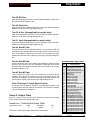
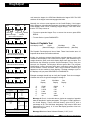
Sequence 3. Display Digits Tests
Initial Display Values:
Credit
8.8.8.8.8.
Win Meter
8.8.8.8.8.
Bet
8.
Several lighted segments make up each display digit. The first test in this
sequence checks all the display segments. In the second test, the I/O Board
sends several digits to all displays. Each display should match the others.
• To enter Series 3, press DIAGNOSTIC after Test 2.
Test 1. Segment ("All 8's") Test
Test 1 lights all display segments in each digit (all 8’s). Dim or blank
segments may indicate a bad display, driver or cable. Check for loose
connectors. To enter Test 2, press DIAGNOSTIC.
Test 2. Digits Test
To check your slot machine's ability to display digits, press
DIAGNOSTIC. Numeral by numeral, each display should light the digit
sequence 1–2–4–8–0. One digit progresses through the sequence.
Then the digit holds a zero, and the next display goes through the
sequence. A display may pass the Segment Test, but fail to reproduce
this digit sequence. That symptom indicates an I/O Board logic fault.
A
F
G
E
B
.
C
D
DP
Display Segments
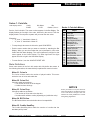
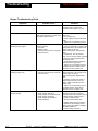
Series 3. Hopper Test
Initial Display Values:
Credit
0
Win Meter
(Blank)
Bet
3
Put at least 40 coins in the hopper for this test. During the test, the Credit
Display counts coins paid out. The Hopper Test checks the...
• Hopper drive circuitry
• Motor brake
• Hopper motor
• Opto coin-out sensor
The I/O Board enables the hopper driver, a solid state relay (SSR). The SSR
switches on the hopper motor and releases the brake. The hopper
dispenses 10 coins. A coin-out sensor detects each coin leaving the hopper.
The sensor transmits this information back to the CPU Board. After the tenth
WMS Service Manual—Slot Machine
16-004339—DIAGNOSTICS/ADJUSTMENTS
Hopper Error Messages
Credit
Display
HPrE
HPrJ
HPrC
Hprr
Subject
Hopper Empty
Hopper Jam
Hpr Dispensed Extra Coin
Hopper Runaway
S1/CH2
2-15
Diag/Adjust
Back to Contents
coin leaves the hopper, the CPU Board disables the hopper SSR. The SSR
switches off the hopper motor and engages the brake.
CREDIT
WIN METER
Normally, the coin-out count appears on the Credit Display. If the hopper
fails to dispense coins after three attempts, the hopper stops. Meanwhile, the
Credit Display reads "HPrE," indicating "Hopper Empty." You'll also notice
that the TILT lamp comes on.
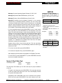
BET
1-Game ID
3-Top Award 5-Max Bet
2-Game Percentage
4-Protocol
Above: 5 Parts of Program ID
• To start or repeat the Hopper Test, or recover from an error, press SPIN
REELS.
• To enter Series 4, press DIAGNOSTIC.
CREDIT
WIN METER
BET
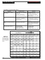
Series 4. Paytable Test
Game Software Release Number
(Alternates with above information)
CREDIT
WIN METER
Credit
(Game ID/Pctage)
Initial Display Values:
WIN METER
The Paytable Test displays six lines of data. These lines itemize some 10
important facts about slot machine software.
Initially, the software program identification number appears on the slot
machine's three displays. This number has five parts. (The illustration in the
margin shows the parts, and which display digits each part occupies. The
table below the illustration provides several examples.) Then, every two
seconds, the Paytable Test displays different game data: The program
identification number alternates with game, operating system, data and
sound software release numbers. Next, the jurisdiction software type
appears on the slot machine's three displays. The data messages cycle on
the displays until you press SPIN REELS or DIAGNOSTIC.
BET
Data Software Release Number
(Alternates with above information)
CREDIT
WIN METER
BET
Sound Software Release Number
(Alternates with above information)
CREDIT
WIN METER
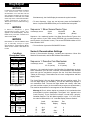
Example messages should help to clarify the Paytable Test’s six messages.
Consider this set of six typical messages A through F...
BET
Credit
Display
Jurisdiction Software Type
(Alternates with above information)
Game ID
(3 digits)
Wild & Loose
Copy Cat
Power 7’s
etc.
92
94
96
etc.
Top Award
(4 digits)
1,000
2,500
500
etc.
Protocol
(1 digit)
None
ACP
SAS
SDS
(Future Use)
VLC
etc.
Max Bet
(1 digit)
0-9: Highest wager that the
machine accepts (in credits)
2-16
A.
B.
C.
D.
E.
F.
Game % (2
digits)
010
011
012
Bet
(Max Bet)
BET
O/S Software Release Number
(Alternates with above information)
CREDIT
Win Meter
(Top Awd/Protocol)
S1/CH2
0
1
2
3
4
5
07296
S rE1
S SYS
S dAt
Sound
Jur
Win Meter
Display
Bet
Display
02000
5.05
5.05
5.00
4.00
StAnd
4
0
Message A. Row A, in the table above, depicts an example of paytable
data as described in earlier paragraphs. The legend, “07296” appears in
the Credit Display. These numerals identify game ID 072, with a
percentage of 96. The Win Meter designates a top award of $200, and
game protocol “0,” (none). A “4” in the Bet Display specifies a four-coin
maximum bet game.
Message B declares Game Software Release (“S rE1”) 5.05.
16-004339—DIAGNOSTICS/ADJUSTMENTS
WMS Service Manual—Slot Machine
Diag/Adjust
Back to Contents
Message C reports Operating System Release (“S SYS”) 5.05.
Message D stipulates Data ROM Release (“S dAt”) 5.00.
Message E refers to Sound ROM Release (“Sound”) 4.00.
Message F identifies the slot software jurisdiction. In our example,
“StAnd” refers to standard jurisdiction software. See the nearby table
Jurisdiction ROMs and Jumpers. Most jurisdictions use standard
software. Special jurisdictions sometimes require their own software. In
addition, special jurisdictions always employ unique jumper settings on
the I/O Board. These settings appear later in this chapter.
• To check paytable awards, press SPIN REELS once for each award.
Each time that you press SPIN REELS, the test advances to the next
award. The reels spin and stop on each winning combination. The stops
reference on the center line. Maximum and minimum paytable awards
alternate in the Win Meter Display. (See the NOTICE in the margin.)
Awards occupy all five digits of the display. (Note this difference: In the
program identification number described above, awards occupy only
four display digits.) The Credit Display indicates the award number. For
instance, a "1" indicates the top award. After each test, the display
indicates the award for that combination.
NOTICE
CHECKING PAYTABLE AWARDS. Any
top award over 99,999 appears in
special notation. In this notation, “t”
stands for the phrase, “times 10,000,
plus...”
Notation
Number
Conventional
0-99,999
xxtxx
100,000-990,099
• In the table, the character x
represents a decimal number.
• Multiply numbers before the character
“t” by 10,000.
• Add numbers after the character “t” to
the product.
Examples:
Suppose that a failure occurs during the test: The test terminates
without completing the spin. The Credit Display indicates the failure type
with an error code.
• 9,000
• 99,999
• 100,000
• 990,099
=
=
=
=
9000
99999
10t00
99t99
Jurisdiction ROMs and Jumpers
Std ROM + Std ROM + Spcl ROM +
Jumpers
No Jumpers Jumpers
(Most Juris- Missouri
Delaware
dictions) New Jersey
France
Note: "Std" = Standard; "Spcl" = Special.
Install standard or special ROM at XU3 on
CPU Board.
• To recover from the failure, press SPIN REELS.
• To continue the Paytable Test, press SPIN REELS again.
After displaying the last award in the paytable, the Paytable Test ends.
• To enter Series 5, press DIAGNOSTIC. Or press SPIN REELS after the
last non-zero award combination.
Series 5. Reel Strip Test
Initial Display Values:
Credit
(Blank)
Win Meter
(Blank)
Bet
5
The Reel Strip Test enables you to check each strip for proper installation
on its reel.
• To begin a reel strip test, press SPIN REELS. The reels spin and stop
at the next symbol (reel stop) on the reel. The Credit Display indicates
the symbol (reel stop) number.
• Repeatedly press SPIN REELS until you've checked all the symbols.
Each time you press SPIN REELS, the reels advance one stop.
WMS Service Manual—Slot Machine
16-004339—DIAGNOSTICS/ADJUSTMENTS
S1/CH2
2-17
Diag/Adjust
Back to Contents
NOTICE
In electronic coin comparators, a sample
coin determines the current
denomination. You must also set the
slot machine computer for the correct
denomination. For this task, use a RAM
Clear Chip of the correct denomination.
Follow instructions in Section 2,
Maintenance and Troubleshooting,
Chapter 2.
NOTICE
In Series 6, Sequence 1, game
denomination (nickel, quarter, etc.)
appears in the Credit Display. The last
RAM Clear procedure installed this
value in static RAM.
NOTICE
DIP switches on the bill validator allow
you to manually accept or reject
denominations. Administration Mode
Series 6 can't override a DIP switch set
to OFF.
Coin Mech
Description Tables
•Credit Display
1st 2 Digits
Display
Model
40
40X*
35
35X*
Last 2 Digits
Display
Country
99
Token
05
Peru
04
S. Africa
03
France
02
Italy
01
Canada
00
U.S.
*Note: 35X = slant top;
40X = upright slot.
•Win Meter Display
1st Digit
Display Coin Mech
2
Smart Mech
1
NRI
0
CC-16
Last 4 Digits
Display
Coin
100
$1
50
50¢
25
25¢
5
5¢
2-18
S1/CH2
Simultaneously, the Credit Display increments the symbol number.
• To enter Sequence 1 from any reel strip test, press the DIAGNOSTIC
button. Or press SPIN REELS after you've checked the last symbol.
Sequence 1. Show Secure Device Type
Credit
SEcur
Initial Display Values:
Win Meter
4-Digit No.
Bet
(Blank)
Sequence 1 is a read-only function. Use Show Secure Device Type to view
the type number of your GD's secure EEPROM. (On machines without a
security device, this number is zero.) The secure EEPROM resides at CPU
Board location XU27.
• To enter Series 6, press the DIAGNOSTIC button.
Series 6. Denomination Settings
Series 6, Denomination Settings, includes two sequences: Show Slot
Machine Denomination, and Set Bill Validator Denomination.
Sequence 1. Describe Coin Mechanism
Initial Display Values:
Credit
35 00 (varies)
Win Meter
0 25 (varies)
Bet
6
Sequence 1 is a read-only function. Use Describe Coin Mechanism to check
which mechanism your GD uses. Describe Coin Mechanism also indicates
what coin type the mechanism accepts. See the Coin Mech Description
Tables (in the margin). These tables list coin mech configurations and their
display codes.
The Credit Display’s first two digits indicate the slot machine model. The
next two digits signify coin nationality. The first Win Meter digit displays a
coin mechanism code. The next four digits denote the currency value that
your slot machine accepts. (A slot machine only accepts one denomination.)
The machine denomination in cents appears on the Win Meter Display.
Message A. Row A, below, depicts an example of coin mechanism data
as described in previous paragraphs. The legend, “40 1” appears in the
Credit Display. These numerals indicate a model 40X (upright),
Canadian machine. The Win Meter specifies a type “1 25” coin mech,
the code for NRI and 25¢. A “6” in the Bet Display refers to Series 6.
A.
B.
C.
D.
Credit
Display
Win Meter
Display
Bet
Display
40 1
Stnd
Jpr
0000
1 25
6
6
6
6
Set 1
0000
16-004339—DIAGNOSTICS/ADJUSTMENTS
WMS Service Manual—Slot Machine
Diag/Adjust
Back to Contents
E.
F.
Jpr
0000
Set 2
0000
6
6
Following the basic coin mechanism message, the displays continue to
flash additional coin information. (See example messages “B” through
“F” above.)
Message B identifies the type of RAM clearance software used at slot
machine initialization. In our example, “Stnd” refers to RAM clearance
software for standard coins. Most jurisdictions use standard coin
software. If your slot machine accepts custom tokens, then it requires
special RAM clearance software.
Message C is the header for Jumper Setting 1 on the I/O Board.
Message D indicates the status of the eight, soldered jumpers for
Setting 1. The Credit Display conveys the high four jumper bits. The Win
Meter Display conveys the low four jumper bits. A “1” signifies a
connected jumper. A “0” signifies an open jumper.
Message E is the header for DIP Switch Setting 2 on the I/O Board.
Message F indicates the status of the eight DIP switches for Setting 2.
The Credit Display conveys the high four switch bits. The Win Meter
Display conveys the low four switch bits. A “1” signifies a connected
switch. A “0” signifies an open switch.
• To enter Sequence 2, press the DIAGNOSTIC button.
Sequence 2. Set Bill Validator Denomination
Initial Display Values:
Credit
1
Win Meter
“on” or "OFF"
Bet
(Blank)
Use Set Bill Validator Denomination to specify which bill values that your slot
machine accepts. A bill value appears on the Credit Display. The Win Meter
display indicates whether the slot machine accepts that denomination. A
Display of “on” means accept, and "OFF" means reject. The Bill Settings
table lists available denominations and their display codes. Continue to
select and accept or reject denominations until you've completed every
denomination.
Bill Settings
Coin/Bill
$100
$50
$20
$10
$5
$2
$1
Display
100
50
20
10
5
2
1
• To select the next denomination, turn the JACKPOT RESET KEY.
• To accept or reject a denomination, press SPIN REELS. Check the Win
Meter Display. A display of “on” means accept, and "OFF" means reject.
• To return to the first denomination, advance to the last denomination.
Then turn the JACKPOT RESET KEY once more.
• To enter Series 7, press the DIAGNOSTIC button.
WMS Service Manual—Slot Machine
16-004339—DIAGNOSTICS/ADJUSTMENTS
S1/CH2
2-19
Diag/Adjust
Back to Contents
Series 7. Maximum Hopper Payout
Initial Display Values:
Credit
HoPr
Win Meter
4-Digit No.
Bet
7
Series 7 selects the maximum number of coins that the hopper dispenses at
once. Series 7 doesn't affect the number of coins paid out for the top award.
Here’s how Series 7 works: A win that equals or exceeds the Maximum
Hopper Payout triggers a hand-pay event. The hand pay equals the
difference between the win and the partial hopper pay amount. (An
attendant must pay the hand pay amount.)
At or above the Maximum Hopper Payout, the GD reacts in either of two
ways...
• In Cash Mode, the machine pays the partial payout amount set at Series
8. Remaining winnings must be hand paid.
• In Credit Mode, the machine increments its Credit Display by the partial
payout amount. Remaining winnings must be hand paid.
Normally, an operator sets Maximum Hopper Payout to accommodate
hopper size. Of course, the machine must never cash out more than hopper
capacity, emptying the hopper. To prevent that situation, the machine
prohibits a credit accumulation beyond the Maximum Hopper Payout.
In Credit Mode...
• If a win exceeds the Maximum Hopper Payout: The hopper provides a
partial payout and a hand pay provides the remainder.
• If a win plus credits on the machine equal or exceed the Maximum
Hopper Payout: The partial pay amount comes out of the hopper.
• If a win plus credits exceed the Maximum Hopper Payout: The hopper
pays the win.
• The slot machine rejects a bill that increases credits up to or beyond the
Maximum Hopper Payout.
The Credit Display indicates the maximum payout setting. The flashing digit
indicates the value to set.
• To increment the flashing digit value, press SPIN REELS.
• To proceed to the next digit, turn the JACKPOT RESET KEY. With each
turn of the key, the flashing digit sequentially advances from right to left.
• To enter Series 8, press the DIAGNOSTIC button.
2-20
S1/CH2
16-004339—DIAGNOSTICS/ADJUSTMENTS
WMS Service Manual—Slot Machine
Diag/Adjust
Back to Contents
Series 8. Hopper Partial Payout Limit
Initial Display Values:
Credit
PArt
Win Meter
4-Digit No.
NOTICE
Bet
8
Series 8 selects the partial payout amount during a hand payout or jackpot.
Select “0000” to allow no partial payout. Your choice appears in the Credit
Display.
The Hopper Partial Payout Limit can't
exceed the Maximum Hopper Payout.
Suppose that you attempt to set up the
machine that way. The machine zeros
any digit that produces an excessive
amount.
The Credit Display indicates the current partial payout amount. The flashing
digit indicates the value to set.
• To change the flashing digit value, press SPIN REELS.
• To proceed to the next digit, turn the JACKPOT RESET KEY. With each
turn of the key, the flashing digit sequentially advances from right to left.
• To enter Series 9, press the DIAGNOSTIC button.
In a hand payout situation, the candle flashes and the machine dispenses
the allowed payout. The Credit Display indicates the amount dispensed. The
Win Meter Display indicates the amount to be hand paid.
Series 9. Progressive ID and Level
The slot machine supports an interface to progressive systems. To use this
system, turn on I/O Board DIP Switch 8 of Bank 2. Then make two settings...
• ID (Range 0 to 32). The slot machine ID.
• Level (Range 0 to 8). The number of active progressive levels on the
system.
Set the DIP Switch and Check the Jurisdiction Jumper
❑
❑
❑
❑
1.
2.
3.
4.
❑
5. Set DIP Switch 8, Bank 2 to "ON." Check to see that your
jurisdiction jumper is in the correct position. See the table I/O
Board Jumper and Dip Switch Settings.
6. Place the I/O Board on a flat surface. Use a ballpoint pen or
small, flatblade screwdriver to set switches as desired.
7. Slide the circuit board back into its card cage slot. Push the
board in firmly, but don't force the board in. Each board is keyed,
and only fits the proper slot. Push the white board ejector tabs
toward the cage. This action engages the board with the blind
mating connector.
❑
❑
Unlock and open the Main Door.
Turn power off at the PDU switch.
Unlock and open the card cage.
The I/O Board is the top card in the card cage. To disengage a
board, pull the inside of its white board ejector tabs toward you.
Remove the board.
WMS Service Manual—Slot Machine
16-004339—DIAGNOSTICS/ADJUSTMENTS
S1/CH2
2-21
Diag/Adjust
Back to Contents
TDA2030A
Sound Amp Chip
TIP107
Row-Drive
Darlingtons
I/O (Top)
Card
TIP102
Column-Drive
Darlingtons
Soldered
Jumpers
PC Board
Ejector Tab
Dip
Switches
DS1 "Fail" LED
❑
!
❑
❑
❑
CAUTION
CAUTION
Power Supply LEDs:
+5V, +12V, -12V, +5V, +18V
8. Clear the RAM by following the procedure in the Maintenance
and Troubleshooting book, Chapter 2.
9. Close and lock the card cage.
10. Turn power on at the PDU switch.
11. Close and lock the Main Door.
To enable the Series 9 progressive
option, turn on DIP Switch 8 of Bank 2.
Otherwise, the progressive option won't
work. After setting the DIP switch, clear
the RAM. Otherwise, Bookkeeping
Totals will report inaccurate values.
Sequence 1. Set Progressive ID
The progressive option only initializes
after you clear the RAM. Turning on the
switch doesn’t disrupt bookkeeping
totals, because the GD won’t recognize
the new switch state.
The ID specifies the Progressive Controller's input from this slot machine.
For instance, suppose that you've plugged the slot machine into Progressive
Input 1. Set the Progressive ID to 1. Never set an ID to zero (an invalid
setting).
Initial Display Values:
Credit
ID
Win Meter
2-Digit No.
Bet
9
If your slot machine doesn’t suport progressive capabilities, the Win Meter
display reads “null.” In machines without progressive capabilities, Sequence
1 is a read-only feature.
• To increment the flashing digit value, press SPIN REELS.
I/O Board Jumper and DIP Switch Settings
1
2
3
4
5
6
7
8
ON
To use Series 9, turn on DIP Switch 8
in Bank 2. (When viewed from the
front of the I/O Board, the DIP Switch
is upside down.)
2-22
S1/CH2
DIP Bank Jurisdiction
1
Standard
(Jumper New Jersey
Pad)
Missouri
France
Delaware
Progressive
2
Enabled
(Switch)
Disabled
8
Off
On
Off
On
Off
7
Off
Off
On
On
Off
6
Off
Off
Off
Off
On
5
Off
Off
Off
Off
Off
4
Off
Off
Off
Off
Off
3
Off
Off
Off
Off
Off
2
Off
Off
Off
Off
Off
1
Off
Off
Off
Off
Off
On
Off
Off
Off
Off
Off
Off
Off
Off
Off
Off
Off
Off
Off
Off
Off
16-004339—DIAGNOSTICS/ADJUSTMENTS
WMS Service Manual—Slot Machine
Diag/Adjust
Back to Contents
• To proceed to the next digit, turn the JACKPOT RESET KEY. Each turn
of the key advances the flashing digit sequentially, from right to left.
• To enter Sequence 2, press the DIAGNOSTIC button.
Sequence 2. Set Progressive Level
Initial Display Values:
Credit
Win Meter
LEUEL
1-Digit No.
!
Bet
9
The Level setting tells the machine how many progressive levels to respond
to.
If your slot machine doesn’t support progressive capabilities, the Win Meter
display reads “null.” In machines without progressive controllers, Sequence
2 is a read-only feature.
• If you select Level 0: The machine doesn’t trigger a progressive
response.
CAUTION
CAUTION
Note PC sheets before setting the
Progressive Level. Some games limit
how high you can set the progressive
level. The machine doesn’t prevent you
from setting the level beyond these
game limits. For instance, suppose that
a game has five levels. The GD won’t
prevent you from setting the Progressive
Level to eight.
• If you select Level 1: Only a maximum coin win on the paytable’s top win
line triggers a progressive win.
• If you select Level 2: Hitting either Level 1 or Level 2 triggers a
progressive win. When a player hits Line 2, he only wins the second line,
Level 2. He’s still eligible to win Line 1 in the future. When a player hits
Line 1, he only wins the first line, Level 1. He’s still eligible to win Line 2
in the future.
• If you select any Level 'X', which is greater than 2: A maximum coin win
on the paytable’s top 'X' win line triggers a progressive win.
• To increment the flashing digit value, press SPIN REELS.
• To enter Series 10, press the DIAGNOSTIC button.
Series 10. Lamp Test
Initial Display Values:
Credit
LAnnP
Win Meter
r7 c3
Bet
0
Series 10 provides a test of all the lamps in the slot machine. This test
supplements the test at Series 2.
Initially, the slot machine displays row and column numbers for the Bet One
Switch lamp. (Row and column numbers refer to the Lamp Matrix. All
microprocessor-controlled lamps are wired into the rows and columns of this
matrix.)
The program blinks one lamp at a time. Pressing MAX BET advances the
test to the next lamp. As each lamp blinks, the Credit Display indicates its
name. Meanwhile, the Win Meter Display indicates the lamp’s row and
WMS Service Manual—Slot Machine
NOTICE
CUSTOM FEATURES. In some slot
machines, the Lamp Test is Sequence 1
of Series 10. These machines also
include a number of “CF” or custom
feature sequences. (For example, a
programmable user message on the
Dotmation display.) These sequences,
which are game-specific and nonstandard, are beyond this manual’s
scope.
16-004339—DIAGNOSTICS/ADJUSTMENTS
S1/CH2
2-23
Diag/Adjust
Back to Contents
column.
The test checks leftmost lamps first. Then the test progresses to lamps on
the right side of the machine.
Here’s the nominal test order...
• Button lamps
• Tilt lamps
• “Insert Coin” lamps
• Denomination lamps
• “Coin Accepted” lamps
• Disclaimer/Payline lamps
• Reel 1 lamps
• Reel 2 lamps
• Reel 3 lamps
• Bill Validator lamps
Game-specific lamps appear either at the beginning or at the end of the test.
(For example, the wheel in Top Cat or the Winning Streak marquee.)
• To advance to the next lamp and test it, press MAX BET.
• Replace burned out bulbs.
Exit to Game Play Mode
• To exit Series 10 and Administration Mode, close and lock the Main
Door. The reels spin and recycle to their previous game positions.
• To reenter Diagnostic Mode, press the DIAGNOSTIC button. A zero
appears in the Bet Display and three digits appear in the Credit Display.
2-24
S1/CH2
16-004339—DIAGNOSTICS/ADJUSTMENTS
WMS Service Manual—Slot Machine
Bookkeeping
Back to Contents
NOTICE
This chapter covers slot software up to
v. 5.09.
Chapter 3. Bookkeeping Mode
During Game Play Mode, the microprocessor continuously updates game
statistics. The system stores this data in the CPU Board's CMOS RAM. In
Bookkeeping Mode, the software arranges data in series of data meters.
Each meter provides game information on one topic. The software stores
related topics in the same series.
The slot machine presents game data as numeric codes on three displays:
The Win Meter, Credit and Bet displays. A data series number appears on
the Bet Display. The Credit and Win Meter displays convey meter data. See
the display illustration below.
Credit Display
Win Meter Display
System
CPU
Static
RAMs
Local
Data
Bus
LD
Address
Bus
XA
EPROMs
Bet Display
$1
CREDIT
The System Stores Game Data
WIN METER
BET
The battery backed, static RAMs maintain data meters during power failures.
The Bookkeeping Meter Series table lists the eight data meter series that
Bookkeeping Mode tracks. Each series contains several meters.
Interrupt
Data
Bus
ID
External
Data
Bus
XD
Data
Bus
BD
Xilinx®
PGA
I/O Port
Data
Bus
GB
Using Bookkeeping Mode
Consult Bookkeeping Mode to record game information regularly and before
repairing the machine.
Enter Bookkeeping Mode
❑
❑
1. You can enter Bookkeeping Mode while the machine operates in
Game-Over Mode or Tilt Mode. (The slot machine enters GameOver Mode between games. No bet or jackpot is pending and the
hopper is inactive. Tilt Mode means that a tilt prevents game play.)
Find the JACKPOT RESET KEY switch near the SLOT HANDLE.
Insert the JACKPOT RESET KEY and turn it clockwise. The slot
machine enters Series 1.
2. Repeatedly turn the JACKPOT RESET KEY to advance between
Bookkeeping Mode series. (Pressing MAX BET serves the same
function as turning the JACKPOT RESET KEY.) Continue until you
find the desired series. The series name appears in the Credit and
Win Meter displays. For instance, in the first series, the word "coin"
appears in the Credit Display. The word "info" appears in the Win
Meter Display.
WMS Service Manual—Slot Machine
16-004340—BOOKKEEPING MODE
Player
Panel
Game Data In...
• Coins In
• Play Info
• Winnings Info
Bookkeeping Meter Series
Credit Win
Meter Series Display Display
coin
inFo
1. Coin Info Meters
2. Play Info Meters PLAY inFo
PLAY
Lo9
3. Play Log
door
inFo
4. Door Info Mtrs
tilt
inFo
5. Tilt Info Meters
bill
inFo
6. Bill Info Meters
bill
Lo9
7. Bill Log
bet
inFo
8. Bet Info Meters
9. Cash Info Meters CASH inFo
LinE
inFo
10. Line Info Meters
Prog
inFo
11. Progr Info Mtrs
S1/CH3
3-1
Bookkeeping
Back to Contents
NOTICE
In this manual, switch or button names
appear in CAPITAL letters. For example,
this manual often instructs you to “press
DIAGNOSTIC.” DIAGNOSTIC is the
DIAGNOSTIC button behind the Main
Door. See the table Bookkeeping Mode
Controls for other common switch
names.
Change
Cash/
Credit
Bet
One
Spin Reels
Max Bet Spin
Player Panel Buttons
Bookkeeping Mode Controls
NOTICE
You can use either the JACKPOT
RESET KEY or MAX BET to select
tests. For simplicity, this chapter only
mentions the JACKPOT RESET KEY.
NOTICE
Switch
• JACKPOT RESET KEY
• MAX BET
• SPIN REELS
❑
3. Press the SPIN REELS button to advance inside a series and view
the next meter. SPIN REELS is on the player panel. The button
lights up to prompt you. For instance, suppose that the Credit and
Win Meter displays indicate "coin info." You press SPIN REELS to
advance to the first meter, Coins In.
❑
4. Observe meter data by reading displays: The five most significant
digits (5MSD) appear in the Credit Display. The five least significant
digits (5LSD) of data appear in the Win Meter Display. The one-digit
Bet Display indicates the meter number, by alternately flashing two
digits. Suppose that you're interested in Coin Meter 01, which
indicates 1.7 million coins in. The displays look this way...
• The Credit Display reads “00017”
• The Win Meter Display reads “00000”
• The Bet Display reads “0,” then “1,” then blank (for Meter 01,
Coins In)
You can use either the SPIN REELS
button or the SLOT HANDLE to initiate
tests. For simplicity, this chapter only
mentions the SPIN REELS button.
NOTICE
You can enter Bookkeeping Mode with
the Main Door open or closed.
NOTICE
You can't enter Bookkeeping Mode from
within Administration Mode.
Bookkeeping Mode Function
Enters Bookkeeping Mode; advances to
the next meter series
Advances to the next meter series. (Easier
to use than JACKPOT RESET KEY)
Advances between meters, within each
series
Exit Bookkeeping Mode
To exit Bookkeeping Mode, either...
• Close the Main Door if it was open. Otherwise open and close the door.
CREDIT
WIN METER
BET
NOTICE
These meter readings represent a Meter
01 value. Here, Meter 01 indicates 1.7
million coins in. (The Bet Display
actually alternates between “0,” “1” and
blank.)
3-2
S1/CH3
• Repeatedly turn the JACKPOT RESET KEY until you exit the last series.
The reels home and game data reappears in the displays. This is GameOver Mode, where players may initiate a game. (If you've left the door
open, a "0" appears in the Credit Display. Game data doesn't appear
until you close the door. A tilted slot machine returns to Tilt Mode,
instead of Game-Over Mode.)
Bookkeeping Mode Displays
This chapter introduces a Bookkeeping Mode series with a highlighted table.
Each table presents initial values for the Credit, Win Meter and Max Bet
displays. Take a look at the table for Series 1 below...
16-004340—BOOKKEEPING MODE
WMS Service Manual—Slot Machine
Bookkeeping
Back to Contents
Series 1. Coin Info
Initial Display Values:
Credit
5 MSD
Win Meter
5 LSD
Bet
flashes 0, then 1
See the Coin Info table. The meter number appears in the Bet Display. The
display flashes the first digit of the code, followed by the second. Then the
display blanks. The sequence repeats until you enter the next series.
Examples...
• “0,” then “1,” then blank = Meter 01
• “0,” then “5,” then blank = Meter 05
• To step through the meters in this series, push SPIN REELS.
• Find the meter number that you want to examine by watching the Bet
Display. When you see the number that you're interested in, look at the
Credit and Win Meter displays. The most significant five digits for that
meter appear in the Credit Display. The least significant five digits
appear from left to right in the Win Meter Display.
• To enter Series 2, turn the JACKPOT RESET KEY.
Meter Definitions
Series 1. Coin Info Meters
Meter
01
02
03
04
05
06
07
08
09
10
11
12
13
14
15
16
17
18
19
20
Subject
Coins In
Coins Out
Coins Drop
Bill Dollars
Credits HandPay
Total Physical Coins In
Normal Coin In
Escrowed Coin In
Error Coin In
Total Physical Coins Out
Hopper Coin Out
Escrow Coin Out
Test Coin Out
Extra Coin Out
Total Electronic Xfer In
Card Credits In
Bonus Credits In
Total Electronic Xfer Out
Card Credits Out
Bonus Credits Out
Some meter names in the Coin Info series don’t fully define the meters. In
the following discussion, the manual briefly explains each meter’s function.
Meter 01. Coins In
The Coins In Meter tracks the number of played credits. This meter
tracks the sum of coins and credits bet.
Meter 02. Coins Out
Coins Out adds two quantities...
• The number of coins out of the hopper
• Credits bet from winnings
NOTICE
Meter 03. Coins Drop
Coins Drop adds two quantities...
• The number of coins sent to the drop box
• Sometimes bill validator credits (depending on jurisdiction rules)
Some jurisdictions require different
meter specifications. Soldered jumpers
on the I/O Board configure the slot
machine for these jurisdictions. Consult
local gaming regulations.
Meter 04. Bill Dollars
The Bill Dollars Meter stores the dollar value of accepted bills.
Meter 05. Credits HandPay
The Credits HandPay Meter adds the number of credits that the
attendant paid by hand.
WMS Service Manual—Slot Machine
16-004340—BOOKKEEPING MODE
S1/CH3
3-3
Bookkeeping
Back to Contents
Meter 06. Total Coins In
Sum of Meters 7, 8 and 9.
Meter 07. Normal Coin In
The Normal Coin In Meter stores the number of coins inserted during
normal game play.
Meter 08. Escrowed Coin In
The Escrowed Coin In Meter records the number of coins accepted at
inappropriate times. These coins may be in the slot machine due to a
coin lockout relay malfunction. Game software doesn’t count these coins
as a bet.
Meter 09. Error Coin In
Number of coins that produced a long coin error (attempted cheat).
Game software doesn’t count these coins as a bet.
Meter 10. Total Coins Out
Sum of meters 11 through 14.
Meter 11. Hopper Coin Out
Number of coins out of the hopper during normal game play.
Meter 12. Escrow Coin Out
Number of coins returned from among the escrowed coins.
Meter 13. Test Coin Out
Number of coins paid out in the Hopper Test.
Meter 14. Extra Coin Out
Number of extra coins paid out.
Meter 15. Total Electronic Transfer In
Sum of meters 16 and 17.
Meter 16. Card Credits In
Number of electronic credits entered into the slot machine.
Meter 17. Bonus Credits In
Number of bonus credits awarded.
Meter 18. Total Electronic Transfer Out
Sum of meters 19 and 20.
Meter 19. Card Credits Out
Number of electronic credits removed from the slot machine.
Meter 20. Bonus Credits Out
Number of bonus credits removed.
3-4
S1/CH3
16-004340—BOOKKEEPING MODE
WMS Service Manual—Slot Machine
Bookkeeping
Back to Contents
Series 2. Play Info
Initial Display Values:
Credit
5 MSD
Win Meter
5 LSD
Bet
flashes 0, then 1
See the Play Info Meters table. The meter number appears in the Bet
Display. The display flashes the first digit of the code, followed by the
second. Then the display blanks. The sequence repeats until you enter the
next series.
• To step through the meters in this series, push SPIN REELS.
• Find the meter number that you want to examine by watching the Bet
Display. When you see the number that you're interested in, look at the
Credit and Win Meter displays. The most significant five digits for that
meter appear in the Credit Display. The least significant five digits
appear from left to right in the Win Meter Display.
Series 2. Play Info Meters
Meter
01
02
03
04
05
06
07
08
09
Subject
Games Played
Games Played Since Reset
Games Played Since Door Close
Games Won
Total Hand Pays
Progressive Wins
Player Count
Average Time Played
Uptime (Playable for X hours)
• To enter Series 3, turn the JACKPOT RESET KEY.
Meter Definitions
Some meter names in this series don’t fully define the meters. In the
following discussion, the manual briefly explains each meter’s function.
Meter 05. Total Hand Pays
The Total Hand Pays Meter tracks the number of hand payouts by the
attendant.
Meter 07. Player Count
Series 3. Play Log Meters
The Player Count Meter estimates how many people have played the
slot machine. After game play and 20 seconds of idle time, the machine
counts one more player.
Meter
01
02
03
04
05
06
07
08
09
10
11
12
13
14
15
16
17
18
19
20
Meter 08. Average Time Played
The Average Time Played Meter reports average play time per player.
Average time appears in seconds.
Series 3. Play Log
Initial Display Values:
Credit
Game No.
Win Meter
Blank
Bet
Blank
See the Play Log Meters table. In the Play Log Meter series, the Bet Display
acts differently than it does in the other meter series. Here, the Bet Display
doesn't flash the meter number. Instead, the number appears in the Credit
Display. Meanwhile, the Win Meter and Bet displays blank. The game
number alternates with game data in the three displays. Credits on the
machine, Credits Won, and Credits Bet appear after the game number.
WMS Service Manual—Slot Machine
16-004340—BOOKKEEPING MODE
S1/CH3
Subject
Last Game Data
Data from Game 1 Before Last
Data from Game 2 Before Last
Data from Game 3 Before Last
Data from Game 4 Before Last
Data from Game 5 Before Last
Data from Game 6 Before Last
Data from Game 7 Before Last
Data from Game 8 Before Last
Data from Game 9 Before Last
Data from Game 10 Before Last
Data from Game 11 Before Last
Data from Game 12 Before Last
Data from Game 13 Before Last
Data from Game 14 Before Last
Data from Game 15 Before Last
Data from Game 16 Before Last
Data from Game 17 Before Last
Data from Game 18 Before Last
Data from Game 19 Before Last
3-5
Bookkeeping
Back to Contents
• To step through the meters in this series, push SPIN REELS.
• Find the game number that you want to examine by watching the Credit
Display. The reels spin and stop at positions corresponding to that
game. The LEDs indicate that game's data. (The Play Log doesn't record
information on Demo Mode games.)
• To enter Series 4, turn the JACKPOT RESET KEY.
Series 4. Door Info
Initial Display Values:
Series 4. Door Info Meters
Meter
01
02
03
04
05
06
07
Subject
Main Door Access
Bill Validator Stacker Access
Bill Validator Door Access
Logic Door Access
Drop Door Access
Jam Service Door Access
Reel Hatch (Hood) Door Access
Credit
5 MSD
Win Meter
5 LSD
Bet
flashes 0, then 1
See the Door Info Meters table. The meter number appears in the Bet
Display. The display flashes the first digit of the code, followed by the
second. Then the display blanks. The sequence repeats until you enter the
next series.
• To step through the meters in this series, push SPIN REELS.
• Find the meter number that you want to examine by watching the Bet
Display. When you see the number that you're interested in, look at the
Credit and Win Meter displays. The most significant five digits for that
meter appear in the Credit Display. The least significant five digits
appear from left to right in the Win Meter Display.
• To enter Series 5, turn the JACKPOT RESET KEY.
Meter Definitions
Some meter names in this series don’t fully define the meters. In the
following discussion, the manual briefly explains each meter’s function.
Meter 01. Main Door Access
Main Door Access signals entry into the slot machine’s Main Door.
Meter 02. Bill Validator Stacker Access
Bill Validator Stacker Access notifies you that someone has removed the
validator’s internal stacker.
Meter 03. Bill Validator Door (Stacker) Access
Bill Validator Door Access signals entry into the bottom DBV door. This
door allows access to the DBV stacker.
Meter 04. Logic Door Access
Logic Door Access notifies you of entry into the card cage.
3-6
S1/CH3
16-004340—BOOKKEEPING MODE
WMS Service Manual—Slot Machine
Bookkeeping
Back to Contents
Series 5. Tilt Info Meters
Meter 05. Drop Door (Cashbox Door) Access
Drop Door Access signals entry into the Cashbox Door.
Meter 06. Bill Jam Service Door Access
Bill Jam Service Door Access signals entry into the top DBV door of the
machine. This door allows access to the DBV reader mechanism.
Meter 07. Hood Access (Not applicable to upright slots)
Hood (Reel Hatch) Access signals entry into the Reel Hatch on the face
of the slot machine.
Series 5. Tilt Info
Initial Display Values:
Credit
5 MSD
Win Meter
5 LSD
Bet
flashes 0, then 5
See the Tilt Info Meters table. The meter number appears in the Bet Display.
The display flashes the first digit of the code, followed by the second. Then
the display blanks. The sequence repeats until you enter the next series.
Detailed troubleshooting procedures usually begin with Tilt Info meter
displays. See the Maintenance and Troubleshooting section.
• To step through the meters in this series, push SPIN REELS.
• Find the meter number that you want to examine by watching the Bet
Display. When you see the number that you're interested in, look at the
Credit and Win Meter displays. The most significant five digits for that
meter appear in the Credit Display. The least significant five digits
appear from left to right in the Win Meter Display.
• To enter Series 6, turn the JACKPOT RESET KEY.
A bill validator fault condition takes the bill validator out of service. Bill
validator faults also cause the bill validator’s external (green) LEDs to
extinguish. The slot machine continues to allow play, but only with coins. To
restore the bill validator to operation, you must service it.
Series 6. Bill Info
Credit
5 MSD
Win Meter
5 LSD
Bet
flashes 0, then 1
See the Bill Info Meters table. The meter number appears in the Bet Display.
The display flashes the first digit of the code, followed by the second. Then
the display blanks. The sequence repeats until you enter the next series.
WMS Service Manual—Slot Machine
Subject
Empty Hopper
Jammed Hopper
Hopper Extra Coin Error
Hopper Runaway Error
Coin Jam
Long Coin
Reversed Coin
Rejected Coin
Bill Validator Communication Fault
Bill Validator Fault
Jammed Bill Validator
Reel Opto Not Seen Error
Reel Opto Seen at Invalid Time Error
Power On Reset
Battery Low or Dead Error
Mechanical Meter Error
Progressive Link Down
No Prog Win Response Confirmation
Fault in Communicating w/ Panel LEDs
I/O Board FPGA Programming Fault
Successful Memory Clear
User Unsuccessful RAM Clr Attempt
Soft RAM Clear
Secure and Game Data Don't Match
Both Sig Copies Corrupt; Clear RAM
Corrupt Main Sig Copy
Corrupt Backup Sig Copy
Both Op Sys Copies Corrupt; Clr*
Corrupt Main Copy of Op Sys Data
Corrupt Backup Copy of Op Sys Data
Both Meter Data Copies Corrupt; Clr*
Corrupt Main Meter Copy
Corrupt Backup Meter Copy
Both GameLog Copies Corrupt; Clr*
Corrupt Main GameLog Copy
Corrupt Backup GameLog Copy
Corrupt Heap
Full Heap
Corrupt Random Number Gen Seed
Corrupt Progressive Data
Both GS* Data Copies Corrupt; Clr*
Corrupt Main Copy of GS* Data
Corrupt Backup Copy of GS* Data
Both PS* Data Copies Corrupt; Clr*
Corrupt Main Copy of PS* Data
Corrupt Backup Copy of PS* Data
Dotmation Communication Error
*NOTE: GS = Game-Specific
PS = Protocol Specific
Clr = Clear the RAM
Bill Validator Fault
Initial Display Values:
Mtr
01
02
03
04
05
06
07
08
09
10
11
12
13
14
15
16
17
18
19
20
21
22
23
24
25
26
27
28
29
30
31
32
33
34
35
36
37
38
39
40
41
42
43
44
45
46
75
16-004340—BOOKKEEPING MODE
Series 6. Bill Info Meters
Mtr
01
02
03
04
05
06
07
08
Subject
Bill Count (resets with stacker removal)
Number of $1 bills inserted
Number of $2 bills inserted
Number of $5 bills inserted
Number of $10 bills inserted
Number of $20 bills inserted
Number of $50 bills inserted
Number of $100 bills inserted
NOTICE
The Bill Info Meter called "Bill Count"
zeroes when you remove the bill
stacker. Zeroing this meter promotes
accurate bill accounting during a
collection.
S1/CH3
3-7
Bookkeeping
Back to Contents
• To step through the meters in this series, push SPIN REELS.
• Find the meter number that you want to examine by watching the Bet
Display. When you see the number that you're interested in, look at the
Credit and Win Meter displays. The most significant five digits for that
meter appear in the Credit Display. The least significant five digits
appear from left to right in the Win Meter Display.
• To enter Series 7, turn the JACKPOT RESET KEY.
Series 7. Bill Log
Initial Display Values:
Series 7. Bill Log Meters
Mtr
01
02
03
04
05
06
07
08
09
10
Subject
Dollar Value of Last Bill Inserted
Dollar Value of Bill Inserted Before Last
$ Value of Bill Inserted 2 Before Last
$ Value of Bill Inserted 3 Before Last
$ Value of Bill Inserted 4 Before Last
$ Value of Bill Inserted 5 Before Last
$ Value of Bill Inserted 6 Before Last
$ Value of Bill Inserted 7 Before Last
$ Value of Bill Inserted 8 Before Last
$ Value of Bill Inserted 9 Before Last
Credit
5 MSD
Win Meter
5 LSD
Bet
flashes 0, then 1
See the Bill Log Meters table. The meter number appears in the Bet Display.
The display flashes the first digit of the code, followed by the second. Then
the display blanks. The sequence repeats until you enter the next series.
• To step through the meters in this series, push SPIN REELS.
• Find the meter number that you want to examine by watching the Bet
Display. When you see the number that you're interested in, look at the
Win Meter Display. The dollar value of the inserted bill appears in the
Win Meter Display.
• To enter Series 8, turn the JACKPOT RESET KEY.
Series 8. Bet Info
Initial Display Values:
Series 8. Bet Info Meters
Mtr
01
02
03
04
05
3-8
Subject
Games Played with 1-Credit Bet
Games Played with 2-Credit Bet
Games Played with 3-Credit Bet
Games Played with 4-Credit Bet
Games Played with 5-Credit Bet
S1/CH3
Credit
5 MSD
Win Meter
5 LSD
Bet
flashes 0, then 1
See the Bet Info Meters table. The meter number appears in the Bet
Display. The display flashes the first digit of the code, followed by the
second. Then the display blanks. The sequence repeats until you enter the
next series.
• To step through the meters in this series, push SPIN REELS.
• Find the meter number that you want to examine by watching the Bet
Display. When you see the number that you're interested in, look at the
Credit and Win Meter displays. The most significant five digits for that
meter appear in the Credit Display. The least significant five digits
appear from left to right in the Win Meter Display.
• To enter Series 7, turn the JACKPOT RESET KEY.
16-004340—BOOKKEEPING MODE
WMS Service Manual—Slot Machine
Bookkeeping
Back to Contents
Series 9. Cash Info
Initial Display Values:
Credit
5 MSD
Series 9. Cash Info Meters
Win Meter
5 LSD
Bet
flashes 0, then 1
See the Cash Info Meters table. Series 9 contains total quantities, not
equalized quantities like the Coin Info series above. For example, if
someone inserts a bill in the machine, but doesn’t play credits, the Series 9
CREDITSINBILL increments, but the COINSIN in Coin Info doesn’t.
Card Credits
Card Credits enter the machine electronically, usually through a host system.
One source of these credits is player tracking or debit cards. The player
inserts the card into an electronic card reader. This reader relays appropriate
information to the central system. The central system orders the slot
machine to accept credits.
Mtr
01
02
03
04
05
06
07
08
09
10
11
12
13
14
15
Subject
Total Credits into Machine from Coins
Total Credits into Machine from Bills
Electronic (Host) Credits In
Total Credits In from Bonus
Total Credits Out from Hopper
Total Credits Out from Attendant
Electronic (Host) Credits Out
Total Credits Out from Bonus
Total Credits Drop from Coins
Total Credits Drop (may include bills,
depending on jurisdiction)
Credits Removed from Credits Won
Credits Bet from Credits Won
Credits Played
Credits Won
Hopper Fill Amount
Bonus Credits
The central system might decide to give the player a bonus. Bonus Credits
enter the machine electronically, usually through a host system.
• To step through the meters in this series, push SPIN REELS.
• Find the meter number that you want to examine by watching the Bet
Display. When you see the number that you're interested in, look at the
Credit and Win Meter displays. The most significant five digits for that
meter appear in the Credit Display. The least significant five digits
appear from left to right in the Win Meter Display.
• To enter Series 7, turn the JACKPOT RESET KEY.
Series 10. Line Info
Initial Display Values:
Credit
5 MSD
Win Meter
5 LSD
Bet
flashes 0, then 1
Line Info meters the number of events that produces a win line combination.
The meter number appears in the Bet Display. The display flashes the first
digit of the code, followed by the second. Then the display blanks. The
sequence repeats until you exit Series 10.
The number of Line Info meters depends on the game’s pay table. For
Example, winning a “top award” increments Meter 1 by one. Winning with the
second best award combination increments Meter 2 by one.
Win line combination reports don’t depend on the bet or payout. For
example, John bets one credit and wins $100. Mary bets three and wins
$300. In either case, three sevens appear on the payline. The slot machine
reports each case as one event.
WMS Service Manual—Slot Machine
16-004340—BOOKKEEPING MODE
S1/CH3
3-9
Bookkeeping
Back to Contents
Buy-a-pay games: The slot machine only reports win line events that
produce a payout.
Some games create many meters for a winning combination. For example,
Mary wins with three matching bars. That combination produces meters for
three “1” bars, three “2” bars, three “3” bars, etc.
• To step through the meters in this series, push SPIN REELS.
• Find the meter number that you want to examine by watching the Bet
Display. When you see the number that you're interested in, look at the
Credit and Win Meter displays. The most significant five digits for that
meter appear in the Credit Display. The least significant five digits
appear from left to right in the Win Meter Display.
• To enter Series 11, turn the JACKPOT RESET KEY.
Series 11. Prog Info
Initial Display Values:
Credit
5 MSD
Win Meter
5 LSD
Bet
flashes 0, then 1
Like Series 10, Series 11 contains a meter for each potential win line
combination. But Series 11 meters only increment for a progressive win at
the corresponding progressive level. (Progressive wins only occur on
maximum coin bets. For example, suppose that a player only bets one coin.
Then he wins the top award combination. Due to his one-coin bet, he can't
win a progressive amount.)
• To step through the meters in this series, push SPIN REELS.
• Find the meter number that you want to examine by watching the Bet
Display. When you see the number that you're interested in, look at the
Credit and Win Meter displays. The most significant five digits for that
meter appear in the Credit Display. The least significant five digits
appear from left to right in the Win Meter Display.
Exit to Game Play Mode
To return to Game Play Mode, close the Main Door. (If the door is already
closed, open and close it.) Or turn the JACKPOT RESET KEY.
3-10
S1/CH3
16-004340—BOOKKEEPING MODE
WMS Service Manual—Slot Machine
Maint
Back Periodic
to Contents
Chapter 1. Periodic Maintenance
Collection and Supply
Regular slot machine collection and supply includes...
• Collecting bills from the bill validator (BV)
• Collecting coins from the pedestal cashbox
• Reading electromechanical meters
•
Collecting Bills from the JCM Bill Validator
❑ 1. Open the BV access door with your key. You'll find this door
near the slot handle. The key also unlocks the handle
mechanism. With the mechanism unlocked, you can pull the
handle down, for easy stacker access.
❑ 2. Push a cassette extraction tool into the doorway.
❑ 3. After the extraction tool mates with the bill cassette, slide out the
extraction tool.
❑ 4. Slide an empty bill cassette through the doorway and into the
BV. Don't use the extraction tool with this empty bill cassette!
Also, take care not to install the cassette upside-down. The
empty cassette's open end should face upward.
❑ 5. Close and lock the BV access door.
•
Collecting Coins
❑ 1. Open the pedestal door with your key.
❑ 2. Slide out the cashbox.
❑ 3. Empty the cashbox.
❑ 4. Replace the cashbox.
❑ 5. Lock the pedestal.
•
Filling the Hopper
❑ 1. Unlock and open the Main Door.
❑ 2. Switch off slot machine power.
❑ 3. To ease the job, you may lift up, disengage and remove the coin
tray.
❑ 4. Add coins as necessary to the hopper.
❑ 5. Replace the coin tray.
❑ 6. Switch on slot machine power.
❑ 7. Close and lock the Main Door.
•
Reading Electromechanical Meters
Observe your jurisdiction’s meter procedures. The slot machine includes
up to six non-resettable, electromechanical meters. The illustration
depicts the meters and provides typical labels. The actual meter labels
depend on your jurisdiction's rules. Don’t confuse electronic (soft)
meters with electromechanical meters.
NOTICE
Follow your jurisdiction's procedures for
logging currency collection.
NOTICE
“GD” stands for gaming device.
NOTICE
Make a permanent record of the number
value on the original meter. Refer to
your jurisdiction's rules for recording
meter readings.
000000
000000
000000
Coins In
Coins Out
Coins Drop
000000
000000
000000
Bills (In $)
Jackpots
Total Drop
Typical Electromechanical Meters
Bill Validator
With proper handling and routine preventive maintenance, you can eliminate
most bill validator malfunctions. The following procedures assure top
performance from JCM® dollar bill validators.
WMS Service Manual—Upright Slot
16-004341—PERIODIC MAINTENANCE
S2/CH1
1-1
Periodic Maint
Back to Contents
Clearing BV Jams
•Open cover.
•
Bill Validator Lamps
Over the bill validator, a lighted sign normally reads "INSERT BILL
FACE UP." This sign also indicates the status of the bill validator. If you
can read the sign, the bill validator is normal. If the sign's lamps go out,
you won't be able to read the "INSERT BILL" message. In that case, the
slot machine has probably shut down the bill validator. (Otherwise, the
bottom two bill validator lamps have burned out. This situation is quite
unlikely.) Routinely check the sign to see if you can read the sign. If you
can't, then service the validator.
•
Cleaning
MAG SENSOR PARTS. Regular cleaning is imperative. Sometimes iron
filings adhere to the magnetic head and head roller. Filings can prevent
your validator from receiving bills.
•Lift upper scanner.
LENSES. To function properly, the bill validator must have clean sensor
lenses and optical reflectors. Periodically cleaning the validator interior
can prevent bill jams. If your validator takes in fewer than 4,000 bills a
week, clean it once a month.
•Remove bill.
What if the validator takes in over 4,000 bills per week? Clean the unit
twice a month.
•
•Also remove cartridge and check for
crumpled bills.
•Clean reader.
!
Reassembly
❑ 1. Lower the upper scanner. Reengage the securing lever.
❑ 2. Close the cover. Push back on the spring-loaded rod at the top
of the unit.
❑ 3. Switch on GD power at the PDU.
❑ 4. Close and lock the Main Door.
CAUTION
CAUTION
• Never use an organic solvent such
as paint thinner.
• Never use compressed air to clean
the bill validator unit!
•
!
CAUTION
WARNING
Avoid electrical shocks! Before working
on the bill validator, turn off slot machine
power.
1-2
S2/CH1
Cleaning Procedure
❑ 1. Unlock and open the Main Door.
❑ 2. Switch off GD power at the PDU.
❑ 3. Pull forward on the spring-loaded rod at the top of the unit. Open
the cover.
❑ 4. Release the securing lever. Lift the upper scanner.
❑ 5. If a bill is jammed in the validator, remove the bill.
❑ 6. The reader with an internal sensor may be dirty. A dirty reader
can cause jams or reduce bill validation accuracy. Regularly
clean the inside of the validator. Use a soft, lint-free cloth or
swab to clean sensor lenses. Soak the cloth or swab with
isopropyl alcohol. Clean oil smudges and fingerprints off the
optical reflector disc.
Simple Repairs
OBSERVE OPERATION. To determine the cause of malfunctions and
detect defective parts, routinely observe validator operation. Before
replacing parts, check the connectors: Do they engage properly? If the
harness appears worn or damaged, replace it.
16-004341—PERIODIC MAINTENANCE
WMS Service Manual—Upright Slot
Periodic Maint
Back to Contents
•
If the Validator Jams...
Follow the steps at Cleaning. If the jam is inside the validator, lift the
sensor plate. Rotate the plate to the front. Remove the bill.
Coin Comparator and Chute
WMS slot machines employ CC-16 Coin Comparitor® brand coin
comparators by Coin Mechanisms®. The model that WMS Gaming uses has
the “D12V inhibit” feature. A coin comparator electronically compares the
incoming coin to a sample coin. The incoming coin passes through a
magnetic field, creating a characteristic signal. The sample coin passes
through an equal magnetic field.
The comparator electronically contrasts the incoming coin signal with the
sample coin signal. If the two signals differ, the internal lockout solenoid
remains inactive. The incoming coin diverts to the "reject" track. Like signals
energize the lockout solenoid. The solenoid allows the incoming coin to
enter the "accept" track.
•
•
Checking Comparator Performance
❑ 1. Switch on the slot machine. Close and lock the Main Door.
❑ 2. Insert the correct coin in the coin slot. The coin comparator
should accept the coin. Be sure that the unit functions
consistently! Repeat this step several times. (You may also want
to run Input Test 10.)
Installing the Sample Coin
❑ 1. Slide the sample coin retainer toward the right side of the
comparator. The illustration shows where to place the sample
coin.
❑ 2. Slip a circulated coin of the proper denomination into the sample
coin retainer. Gently release the retainer. The sample coin
retainer should tightly secure the sample coin.
!
JCM Bill Validator DIP Switch
Settings. Your JCM dollar bill validator
has two DIP switch banks. One bank
has eight switches, and the other has
two. The factory setting for these JCM
DIP switches is switch 8 on. All other
switches are off. Don't change these
settings! Changes can cause the bill
validator to malfunction.
1
2
1
2 ON
3
4
5
6
7
8
ON
145 SERIES HEAD
JCM Bill Validator DIP
Switch Settings
1
2
3
4
5
6
7
8
9
10
ON
200 SERIES HEAD
1
Sample Coin
CAUTION
CAUTION
2
3
4
5
6
ON
Counterweight
Sensor Coil
Sample Coin Retainer
Chute Coil
Retainer Spring
12V Indicator LED
Connector
+
Wedge
Fastening
Screw
Fine Tuning Pot
Wedge Goes Here
Wedge
Coin Comparator (Front)
WMS Service Manual—Upright Slot
Coin Comparator (Back)
16-004341—PERIODIC MAINTENANCE
S2/CH1
1-3
Periodic Maint
!
Back to Contents
CAUTION
CAUTION
Prevent comparator or slot machine
damage! Before turning on the machine,
perform the following tests...
•
Be sure that the comparator mounts
securely to the coin chassis.
•
Check entry chute alignment by
inserting the correct coin or an
alignment tool. Coins should fall
easily through the comparator and
exit the reject chute.
•
Route and fasten harness wires
away from moving parts (for
example, the reels).
Coin Comparator Specs for CC-16 Model
Pin
Function
1
Lockout Enable
2
"Coin In" Output Signal
3
Not Connected
4
Not Connected
5
+12 VDC
6
Ground
Coin Diameter Range 0.705-1.575” (17.9-40mm)
Max. Coin Thickness 0.100” (2.54 mm)
NOTICE
For coin demominations between 5¢ and
25¢, use a coin mechanism wedge.
•
!
Positioning the Coin Entry for a Different Denomination
Slot machines manufactured after March, 1995 have a fixed coin
comparator bracket. Installing a different coin comparator requires a
realignment of the coin comparator and coin entry.
CAUTION
WARNING
Avoid electrical shocks! Before working
on the comparator, turn off slot machine
power.
With proper entry-to-chute assembly, coin jams are quite rare. Follow
this assembly procedure...
NOTICE
❑
To find coin entry part numbers for each
denomination, refer to Section 3, Parts.
❑
Mounting Hole Plate Table
Game
Use Plate
Denomination Part Number
5¢
01-13676-03
25¢
01-13676-02
50¢
01-13676-04
US $1
01-13676-01
❑
❑
❑
Coin Comparator Table
Weight
Range (oz.)
0.154-0.238
Coin
Dia
Denomination
(Inch)
•US 5¢
0.705-1.250
•US 25¢
•US 50¢
0.705-1.250
•SA 1R
•US $1
1.250-1.575
—
Dia (mm)
Weight
17.907Range (g.)
31.750
4.4-6.8
17.90731.750
6.9-19.6
31.75040.005
19.7 +
17.9070.705-1.250
31.750
2.2-4.3
17.9070.700-1.250 17.78-1.250 5.5-10.4
—
0.700-1.250 17.78-1.250
•SA 1 Rand
1-4
1. Follow disassembly instructions at Removing the Coin
Comparator, in this chapter.
2. Remove the two Phillips screws that fasten the coin entry to the
player panel.
3. Remove the coin entry from the player panel.
4. Remove two nuts that secure the mounting hole plate to its
mounting studs. If your machine doesn't have a mounting plate,
see the NOTICES in the margin.
5. Remove the plate from the two studs in the player panel.
S2/CH1
2.0-3.0
0.242-0.686
0.690+
Thickness
Thickness Comparator
Range (In.) Range (mm) Part Number
0.05-0.086 1.27-2.184 09-42000-1
0.05-0.086
1.27-2.184
09-42000-3
0.075-0.115 1.905-2.921 09-42000-2
0.077-0.151
0.05-0.086
1.27-2.184
09-42000-4
0.193-0.364
0.05-0.115
1.27-2.921
09-42000-6
0.07-0.105
0.05-0.085
1.27-2.159
09-42000-7
16-004341—PERIODIC MAINTENANCE
WMS Service Manual—Upright Slot
Periodic Maint
Back to Contents
Reassembly
❑ 1. Be sure that you have the right mounting hole plate for your coin
comparator’s denomination. (Each coin denomination requires
its own plate.) Position the plate over the two studs in the player
panel. The plate should fit flush against the player panel. Don’t
force the plate. It only goes on one way. If your machine doesn't
have a mounting plate, see the NOTICES in the margin.
❑ 2. Secure the mounting hole plate to its mounting studs with two
KEPS nuts. After installation, the plate should cover all but two
coin entry mounting holes.
❑ 3. Place the coin entry on the player panel, roughly in position.
❑ 4. Notice the screw holes beside the top two bracket mounting
studs. Mount the coin entry with two Phillips screws in these
holes.
❑ 5. Follow Reassembly instructions at Removing the Coin
Comparator, in this chapter.
•
Sample Coin
Counterweight
Sensor Coil
Sample Coin Retainer
12V Indicator LED
Connector
+
Fine Tuning Pot
Wedge Goes Here
Coin Comparator (Front)
Removing the Coin Comparator
❑
❑
❑
❑
1. Unlock and open the Main Door.
2. Switch off slot machine power.
3. Remove the cable that connects the comparator and Opto
Board: Grasp the plug and pull it off the jack.
4. Remove the coin comparator: Raise the coin comparator
slightly. Pull the bottom out. Then pull the coin comparator down
and out of the machine. Set it aside for reassembly.
Reassembly
❑ 1. Mount the comparator: Slide the top comparator stud upward,
against the bracket. Engage the top comparator stud with the
top bracket notch. Pivot and lower the comparator base until the
comparator engages the bottom notch. Check to see that the
comparator seats properly.
❑ 2. Replace the cable that connects the comparator and Opto
Board.
❑ 3. Switch on slot machine power.
❑ 4. Close and lock the Main Door.
•
Removing Opto Board from GDs w/One Belly Fluorescent Lamp
❑ 1. Unlock and open the Main Door.
❑ 2. Switch off slot machine power.
❑ 3. The Opto Board has two parts, the Receiver Board and the
Transmitter (LED) Board. Find the Receiver Board inside the
door, on the back of the coin chute. Unplug the two Receiver
Board connectors.
❑ 4. Support the belly glass. Inside the door, raise black metal
latches at either side of the belly lamp tray. You'll find these
latches just below the back of the player panel (control panel).
WMS Service Manual—Upright Slot
16-004341—PERIODIC MAINTENANCE
S2/CH1
1-5
Periodic Maint
Back to Contents
❑
❑
❑
❑
5. Lower and remove the belly glass and frame.
6. Examine the lamp tray just above the single, belly fluorescent
lamp. On the latch (right) side of the door, you’ll notice two
access holes. Insert a Phillips screwdriver into one of these
holes. Remove one of the Phillips screws that fasten the
Transmitter Board. Remove the other screw from the second
access hole.
7. Inside the Main Door, unplug the two Receiver Board
connectors. Remove Phillips screws that fasten the Receiver
Board.
8. Remove the Transmitter Board and the Receiver Board.
Reassembly
❑ 1. Position the new Transmitter Board: Place it on the coin chute
side that bolts to the lamp tray. Position the new Receiver Board
on the opposite side of the coin chute. Each optotransistor
should face an LED through a hole in the coin chute. Be sure
that you don't mount the boards backwards! Otherwise, optos
and LEDs won't align with their holes.
❑ 2. Inside the Main Door, replace Phillips screws that fasten the
Receiver Board.
❑ 3. Engage a Phillips screw (removed earlier) on your Phillips
screwdriver. Insert the screwdriver into one of the lamp tray
access holes. Fasten down one side of the Transmitter Board
with this screw. Replace the other Transmitter Board screw at
the second access hole.
❑ 4. Replace and raise the belly glass and frame.
❑ 5. Support the belly glass. Inside the door, lower black metal
latches at either side of the belly lamp tray. You'll find these
latches just below the back of the player panel (control panel).
❑ 6. Plug in the two Receiver Board connectors.
❑ 7. Switch on slot machine power.
❑ 8. Close and lock the Main Door.
•
1-6
S2/CH1
Removing Opto Board from GDs w/Two Belly Fluorescent Lamps
❑ 1. Unlock and open the Main Door.
❑ 2. Switch off slot machine power.
❑ 3. The Opto Board has two parts, the Receiver Board and the
Transmitter (LED) Board. Find the Receiver Board inside the
door, on the back of the coin chute. Unplug the two Receiver
Board connectors.
❑ 4. Unplug the coin chute solenoid connector.
❑ 5. Support the belly glass. Inside the door, raise black metal
latches at either side of the belly lamp tray. You'll find these
latches just below the back of the player panel (control panel).
❑ 6. Lower and remove the belly glass and frame.
❑ 7. You'll notice two belly fluorescent lamps. Carefully grasp one of
16-004341—PERIODIC MAINTENANCE
WMS Service Manual—Upright Slot
Periodic Maint
Back to Contents
❑
8.
❑
❑
9.
10.
❑
11.
the belly lamps. Twist the fluorescent lamp in either direction
until its pins come free of the sockets. Remove the lamp. If your
GD has a second fluorescent lamp, remove it in the same way.
Support the coin chute. Remove four Phillips screws that secure
the chute to the lamp tray. These screws are near the latch end
of the door.
Remove the coin chute.
Remove Phillips screws that fasten the Transmitter Board and
Receiver Board. Each board has two screws.
Remove the Transmitter Board and the Receiver Board.
Reassembly
❑ 1. Position the new Transmitter Board: Place it on the coin chute
side that bolts to the lamp tray. Position the new Receiver Board
on the opposite side of the coin chute. Each optotransistor
should face an LED through a hole in the coin chute. Be sure
that you don't mount the boards backwards! Otherwise, optos
and LEDs won't align with their holes.
❑ 2. Fasten the Transmitter Board with two Phillips screws. Fasten
the Receiver Board in the same way.
❑ 3. Position the coin chute on the lamp tray.
❑ 4. Support the coin chute. Replace four Phillips screws that secure
the chute to the lamp tray. The screw holes are near the latch
side of the door.
❑ 5. Replace the belly fluorescent lamps: Carefully grasp one lamp.
Slide the lamp into its socket slots. Twist the lamp in either
direction until its pins engage with the sockets. Replace the
second fluorescent lamp in the same way.
❑ 6. Replace and raise the belly glass and frame.
❑ 7. Support the belly glass. Inside the door, lower black metal
latches at either side of the belly lamp tray. You'll find these
latches just below the back of the player panel (control panel).
❑ 8. Plug in the coin chute solenoid connector.
❑ 9. Plug in the two Receiver Board connectors.
❑ 10. Switch on slot machine power.
❑ 11. Close and lock the Main Door.
NOTICE
The glass frame in recently
manufactured machines doesn’t
require foam tape.
Glass
•
Replacing Belly Glass
❑ 1. Unlock and open the Main Door.
❑ 2. Switch off slot machine power.
❑ 3. Support the belly glass. Raise the left and right black metal
latches at either side of the belly tray. You'll find them just below
the back of the player panel.
❑ 4. Tilt the belly glass frame downward, to a 45 degree angle with
the slot machine door. Pull the belly glass frame straight back
until the hinge tabs disengage from the machine.
WMS Service Manual—Upright Slot
16-004341—PERIODIC MAINTENANCE
S2/CH1
1-7
Periodic Maint
Back to Contents
❑
❑
❑
!
5. Using an 11/32” nut driver, loosen four #8 KEPS nuts on the
glass retaining bracket.
6. Slide the glass retaining bracket out of the frame.
7. Carefully remove the belly glass from its frame.
Reassembly
❑ 1. Carefully replace the belly glass in its frame. Position the top of
the glass in the frame first. Then press the bottom of the glass
against the frame's foam tape. If the tape is worn out, replace it.
❑ 2. Slide the glass retaining bracket into the frame.
❑ 3. Using an 11/32” nut driver, tighten four #8 KEPS nuts on the
glass retaining bracket.
❑ 4. Hold the belly glass frame at a 45 degree angle to the slot
machine front. Slide the belly glass hinge tabs straight forward
into the belly slots.
❑ 5. Raise the belly glass frame. Hold it tight against the door. Lock
down black metal latches at either side of the belly lamp tray.
You'll find them just below the back of the player panel.
❑ 6. Switch on slot machine power.
❑ 7. Close and lock the Main Door.
CAUTION
WARNING
Take care when working on old
topbox glass. This warning
especially applies to broken or
cracked glass, which can cause
severe wounds.
•
Removing the Topbox Glass
❑ 1. Unlock and open the Main Door.
❑ 2. Switch off slot machine power at the Power Distribution Unit
(inside the Main Door).
❑ 3. Lift the topbox glass by its bottom support bracket. The glass
will disengage from the slot machine gutter. Gently pull the glass
away from the machine.
❑ 4. If a topbox cable connects to the back of the glass, unplug the
cable. Remove the glass. Be particularly careful of fragile
shadowboxes that may be glued or taped to the glass. Also,
take care not to damage the player tracking harness. Set the
glass aside in a safe place.
❑ 5. GDs Without Faceplates or PTUs: Remove the metal, glasssupport bracket bonded to the bottom of the glass. You can pry
the bracket free from the glass with a flatblade screwdriver. GDs
With Faceplates or PTUs: Loosen three retaining nuts on the
faceplate bracket. Remove the bracket. Save the bracket or
faceplate for reassembly.
Reassembly
❑ 1. Pick up the bracket or faceplate that you removed from the old
glass. GDs Without Faceplates or PTUs: Use RTV® or
equivalent glue for this step. Bond the glass-support bracket to
the bottom of the glass. GDs With Faceplates or PTUs: Position
the faceplate bracket on the bottom of the glass. Tighten three
retaining nuts on the faceplate bracket.
❑ 2. If a topbox cable connects to the back of the glass, plug in the
cable.
❑ 3. Replace the glass. Seat the topbox glass-support bracket
1-8
S2/CH1
16-004341—PERIODIC MAINTENANCE
WMS Service Manual—Upright Slot
Periodic Maint
Back to Contents
❑
❑
securely in the slot machine gutter.
4. Switch on slot machine power at the Power Distribution Unit
(near the Main Door hinge).
5. Close and lock the Main Door.
Hopper
•
Removing the Hopper
❑ 1. Unlock and open the Main Door.
❑ 2. Switch off slot machine power.
❑ 3. Lift up, disengage and remove the coin tray.
❑ 4. Slide the hopper out. Sensors and power unplug from the blind
mating connector as you slide the unit out.
Reassembly
❑ 1. Slide the hopper back into position. Sensors and power
reengage at the blind mating connector as you slide the unit in.
❑ 2. Replace the coin tray.
❑ 3. Switch on slot machine power.
❑ 4. Close and lock the Main Door.
NOTICE
Hopper bowl mounting hardware varies
according to the hopper denomination.
Not all screws are the same type. Some
screws include hardware such as
springs or spacers. Replace screws,
springs and spacers in exactly the same
location that you removed them from.
NOTICE
•
Replacing the Hopper Knife
❑ 1. Unlock and open the Main Door.
❑ 2. Switch off slot machine power.
❑ 3. Lift up, disengage and remove the coin tray.
❑ 4. Remove coins from the hopper.
❑ 5. Slide the hopper out. Sensors and power unplug from the blind
mating connector as you slide the unit out.
❑ 6. Set the hopper on a table.
❑ 7. Unplug the two quick disconnect terminals of the hopper bowl
sensor wires.
❑ 8. Use a #2 metric Phillips screwdriver for this step. Orient the
hopper so that the pinwheel faces frontward. Remove the four
screws that fasten the hopper bowl to the hopper. Some of
these screws may include tension springs or spacers. As you
remove this mounting hardware, note its location on the hopper.
Save screws and other hardware for reassembly. Remove the
bowl.
❑ 9. Use a #2 metric Phillips screwdriver for this step. Remove three
Phillips screws that secure the coin exit cover plate. The coin
exit cover plate resides at the top, left side of the pinwheel.
❑ 10. Remove the cover plate. Now you’ll be able to see the knife,
which was under the cover plate.
❑ 11. Use a 7mm wrench for this step. Turn the hopper around, so
that the motor faces frontward. Remove two hex nuts that
secure the knife to the aluminum frame. The frame is the
cylinder that surrounds the hopper pinwheel.
❑ 12. Use a 7mm wrench for this step. Turn the hopper around, so
that the pinwheel faces frontward. The hex head, knife bolts
WMS Service Manual—Upright Slot
16-004341—PERIODIC MAINTENANCE
During disassembly, you may find shim
washers on screws between the knife
and the frame. During reassembly,
replace these shims in the same
locations where you found them.
Installation of Knife
S2/CH1
1-9
Periodic Maint
Back to Contents
NOTICE
During disassembly, you may find shim
washers on screws between the knife
and the frame. During reassembly,
replace these shims in the same
locations where you found them.
❑
Reassembly
❑ 1. Orient the hopper so that the pinwheel faces frontward. Properly
position the new hopper knife, mounting bolts, lock washers and
shims. Loosely install the hopper knife bolts.
❑ 2. Prop up the knife with metal shims that came with the hopper.
❑ 3. Tighten the knife bolts with a 7mm wrench.
❑ 4. For this step, use a feeler gauge. A suitable gauge is available
from hardware and auto stores. Place the feeler gauge under
the knife tip, between the tip and the pinwheel. Use the gauge to
measure the gap between the knife and the pinwheel. Your goal
is to achieve the proper measurement, 0.2mm, or 0.008 inch. As
necessary, repeat steps 2 through 4. Use fewer or additional
shims to regap the knife until you obtain the specified gap.
❑ 5. Use a 7mm wrench for this step. Turn the hopper around, so
that the motor faces frontward. Replace two hex nuts that
secure the knife to the aluminum frame.
❑ 6. Turn the hopper around, so that the pinwheel faces frontward.
Position the coin exit cover plate over the knife.
❑ 7. Use a #2 metric Phillips screwdriver for this step. Replace the
three Phillips screws that secure the coin exit cover plate.
❑ 8. Use a #2 metric Phillips screwdriver for this step. Replace the
hopper bowl. Be sure to replace hardware exactly where it came
off the hopper during disassembly.
❑ 9. Reconnect the bowl sensor wires, by plugging in two quick
disconnect terminals.
❑ 10. Slide the hopper back into position. Sensors and power
reengage at the blind mating connector as you slide the unit in.
❑ 11. Replace the hopper coins.
❑ 12. Replace the coin tray.
❑ 13. Switch on slot machine power.
❑ 14. Perform a software test of the Hopper. GD software includes a
hopper test in Administration Mode. This test dispenses 10
coins.
❑ 15. If the hopper fails the test, troubleshoot the hopper. Otherwise,
close and lock the Main Door.
NOTICE
When installing a $.05 knife, be sure to
use an M4 x 10 x 10 flat washer with
each mounting bolt. This will prevent the
lock washer from jamming into the bolt
hole.
•
1-10
S2/CH1
reside at the top, right side of the frame. Loosen the knife bolts.
Remove the bolts, knife and shims together. Save them for
reassembly.
13. Remove the old hopper knife.
Setting the Hopper Probe Level
❑ 1. Unlock and open the Main Door.
❑ 2. Switch off GD power.
❑ 3. Lift up, disengage and remove the coin tray.
❑ 4. Remove coins from the hopper.
❑ 5. Slide the hopper out. Sensors and power unplug from the blind
mating connector as you slide the unit out.
❑ 6. Inspect the hopper: Before filling the hopper with coins, remove
dust, dirt, loose hardware and other foreign matter. The hopper
must be clean, or it can jam!
16-004341—PERIODIC MAINTENANCE
WMS Service Manual—Upright Slot
Periodic Maint
Back to Contents
❑
7. See the table Hopper Probe Level. Adjust the hopper coin-level
probe. Move the probe to a higher hole if the hopper will hold
more coins. Move the probe to a lower hole if the hopper will
hold fewer coins.
Reassembly
❑ 1. Check the hopper-full probe cable. Make sure that it attaches
firmly through quick disconnects on the probe and bowl ground.
❑ 2. Fill the hopper with coins of the proper denomination. See the
table Hopper Probe Level. The table provides the optimum
number of coins for each coin-level probe hole.
❑ 3. Slide the hopper back into position. Sensors and power
reengage at the blind mating connector as you slide the unit in.
❑ 4. Check that the hopper's mounting base firmly engages both rails
of the track.
❑ 5. Replace the coin tray.
❑ 6. Switch on GD power and check the hopper. Use Series 1, Input
Test 15 of your GD’s Administration Mode diagnostic and
adjustment software. This test will help you to check probe
function. Hopper works: Proceed to the next step. Hopper
doesn't work: Switch off GD power. Double-check cable
connections and the hopper. Repeat this step until the hopper
passes Input Test 15.
❑ 7. Close and lock the Main Door.
•
Vertically Aligning the Hopper Coin-Out Sensor
❑ 1. Unlock and open the Main Door.
❑ 2. Switch off slot machine power.
❑ 3. Lift up, disengage and remove the coin tray.
❑ 4. Slide the hopper out. Sensors and power unplug from the blind
mating connector as you slide the unit out.
❑ 5. Set the hopper on a table.
❑ 6. Find the motor lock lever on the motor. Release the lever by
pushing it down. Spin the hopper shaft.
❑ 7. Stop the hopper when a coin reaches top dead center on the
counting lever roller.
❑ 8. The hopper coin-out sensor is a capacitive proximity sensor.
Find the black, proximity sensor fork that resides between the
circuit board and the motor. This sensor fork straddles the coin
counting flag. Two screws allow you to adjust the fork sideways,
for best fork-to-flag fit. This first set of screws is above the fork.
Two other screws allow you to adjust the fork up and down on
the flag. This second set of screws is below the fork. Loosen the
second set of screws. By moving the sensor fork, align bottom
edges of the coin counting flag and fork.
❑ 9. Tighten the screws.
5
4
2
3
1
Probe Holes
Hopper Probe Level
Probe
Hole
5
4
3
2
1
U.S. $1
1,080
710
680
530
330
25¢
4,080
3,030
2,410
2,150
1,730
5¢
4,820
3,600
2,850
2,560
1,900
Coin
25¢
Coin
Counting
Flag
Sensor Fork
Adjust screws
from back of
disk
Coin-Out Sensor (Looking
Through Hopper Disk)
Reassembly
❑ 1. Slide the hopper back into position. Sensors and power
reengage at the blind mating connector as you slide the unit in.
WMS Service Manual—Upright Slot
16-004341—PERIODIC MAINTENANCE
S2/CH1
1-11
Periodic Maint
Button
Housing
Back to Contents
Button
❑
❑
❑
Door
Support
❑
Nut
❑
Bulb
Grasp
Lamp
Bracket
Here
Switch
(Removable)
2. Replace the coin tray.
3. Switch on slot machine power.
4. Run Series 1, Input Test 14 of your GD’s Administration Mode
diagnostic and adjustment software. This test will help you to
check proximity sensor operation. As necessary, make
adjustments and repeat this step until you are satisfied with
equipment performance.
5. Run the Hopper Test, Series 3 of your GD’s Administration
Mode diagnostic and adjustment software. This test will help you
to verify that the hopper counts coins correctly. As necessary,
make adjustments and repeat this step until you are satisfied
with equipment performance.
6. Close and lock the Main Door.
Lamps
•
Removing Buttons and Replacing Bulbs
❑ 1. Unlock and open the Main Door.
❑ 2. Switch off slot machine power.
Wire Lead
DBV Lamp Board
Reel Glass
Reel Fluorescent Tube
Bill Validator
Aperture (fits
beak)
Payline Lamp Board
Twist Knob to
Remove WedgeBase Bulb
Back of Player
Panel
Reel Display Board
(Credit, Win Meter, Bet)
Belly Glass Release
Lever (1 of 2)
Belly Glass Release Lever (1 of 2)
Coin
Comparator
MAX BET SPIN
SPIN
REELS
BET 1
CASH
CREDIT
CALL
ATTEN.
Quad Opto Board
Fluorescent Lamp Tray
(Back of Belly)
Reel Tube Starter
Chute
Solenoid
Belly Tube Starter
Reel Tube Ballast
Inside of Front Door
1-12
S2/CH1
Belly Tube Ballast
16-004341—PERIODIC MAINTENANCE
WMS Service Manual—Upright Slot
Periodic Maint
Back to Contents
!
❑
❑
❑
3. Grasp the lamp bracket just behind the plastic nut. Hold the top
of the button so that it won't pop off. Firmly rock the lamp
bracket back and forth until it disengages from the button
housing. Then pull the lamp bracket away from the button
housing. (Take care not to bend switch leads.)
4. Grasp and pull the old bulb straight out.
5. If necessary, remove the button housing by unscrewing the
notched, plastic nut. Lift the button housing off the Main Door.
CAUTION
WARNING
Electric shock hazard! Unplug the slot
machine before working on the Power
Distribution Unit or power transformer.
Warning Labels
Power
On/Off
Switch
FU SE
Reassembly
❑ 1. Replace the bulb. Use a type CM86 or equivalent bulb.
❑ 2. Replace the button housing through the button hole. Make sure
that the letters read right-side up. Secure the button housing by
screwing the plastic nut onto the housing. (The serrated edge of
the plastic nut should face the player panel.)
❑ 3. Hold down the button and snap the lamp bracket back on. Test
the button to be sure that the bracket seats properly.
❑ 4. Switch on slot machine power.
❑ 5. Close and lock the Main Door.
Main
Fuse
Power Distribution Unit
•
Replacing Power Distribution Unit Fuses
❑ 1. Unlock and open the Main Door.
❑ 2. Switch off slot machine power. The main power fuse is part of
the slot machine's Power Distribution Unit. As shown on the
illustration, the fuse is on the PDU front panel.
❑ 3. Unscrew the plastic fuse knob.
Reassembly
❑ 1. Replace the fuse. (In 110-volt GDs, use a 4ASB, 250V fuse. In
220-volt GDs, use a 2ASB, 250V fuse.)
❑ 2. Return the knob to its position on the PDU front panel.
❑ 3. Twist the plastic fuse knob until it reengages.
❑ 4. Switch on slot machine power.
❑ 5. Close and lock the Main Door.
Reels
•
!
16-004341—PERIODIC MAINTENANCE
CAUTION
CAUTION
Don't move reel cables from their factory
positions on the chassis. If you replace a
cable: Route the new cable to the same
reel that the old cable served. Routing
cables to the wrong reels causes serious
and difficult-to-trace malfunctions.
!
Replacing and Aligning a Reel Strip
❑ 1. Unlock and open the Main Door.
❑ 2. Switch off GD power at the PDU.
❑ 3. Unplug the cable to the Reel Motor Control Board. The reel
motor cable plug is in front of the reel mechanism. Take care not
to damage delicate mass termination connector pins!
❑ 4. Lift up the thumb lever in front of the reel mechanism that you
want to remove.
❑ 5. Slide the front leg of the reel mechanism out from under the
thumb lever.
❑ 6. Remove the reel mechanism.
WMS Service Manual—Upright Slot
Power Distribution
Unit, Front View
CAUTION
CAUTION
Don't over-torque reel mechanism clips!
NOTICE
Some slot reel games employ two of the
same reel strip. For example, your game
may require two copies of Reel Strip ‘A’
and one Reel Strip ‘B’. If so, mount a
copy of Reel Strip ‘A’ at Position ‘A’ and
Position ‘C’. Mount the remaining reel
strip, marked ‘B’, at Position ‘B’.
S2/CH1
1-13
Periodic Maint
Back to Contents
Top of Reel Strip
7
RAB
❑
Double-Sided
Adhesive Tape
on Back of Strip
❑
❑
❑
Reassembly
Reel strips differ, but the three reel mechanisms are identical. Still, you
must put the proper reel strip on each reel. That is, Reel Strip ‘A’ must
be installed on the reel at Position ‘A’. (As you face the machine, the
leftmost reel occupies position ‘A’. Position 'B' is the next position to the
right, and so forth.)
Bottom of Reel Strip
Apply Tape
The top of each reel strip bears an ‘A’, ‘B’ or ‘C’. Match each strip to the
reel at the appropriate position. (As a reminder, some chassis include a
reel position label under each reel mechanism.) If you ever interchange
reel mechanism positions, also interchange the reel strips. A strip must
remain in the designated reel position. Yet the strip need not remain on
the same reel.
Bottom of
Reel Strip
Reel movement also affects reel strip placement. The reel revolves
down. The leading edge of the strip should be on the outside of the strip
overlap. That way, if the trailing edge comes loose, players can still use
the GD. With the strip installed this way, reel spin tends to hold the strip
to the reel.
Double-Sided
Adhesive Tape
❑
❑
Top End of
Reel Strip
Double-Sided
Adhesive Tape
❑
Opto
Interuptor
Tab
❑
❑
1-14
7. Turn the reel until you find the reel strip seam. Slide your
fingernails under the edge of the seam and raise the strip
slightly. Lift the strip by the seam.
8. Remove the reel strip from the reel.
9. If you plan to reuse the same reel strip, you must replace the
mounting tape. Remove the old tape from the back of the reel
strip.
10. Inspect the reel for wobble that may indicate a worn core. If you
notice wear at the motor T-drive, replace the reel.
S2/CH1
1. Apply a piece of double-sided adhesive tape horizontally across
the top (print reads normally) of the back of the reel strip. Also
put two pieces of tape along the sides near the bottom of the
reel, again on the back side.
2. Find the brace that has two sets of holes. Align the bottom of
the reel strip with the bottom edge of this horizontal brace, after
removing the backing from the bottom two tape strips. Seal the
reel strip to the reel by pushing the reel strip against the reel.
Support the inside of the reel with your hand to avoid deforming
the reel.
3. Turn the reel basket to wrap the new reel strip around the reel.
The reel strip symbols should be right-side up. Be careful that
you aren’t mounting it upside-down!
4. Remove the backing from the top tape strip. Using hand
pressure as above, seal the tape and reel strip to the reel. The
top of the reel strip must now adhere tightly to the horizontal
tape strip.
5. Align the three opto interrupter tabs: The opto stop is usually the
first symbol or the jackpot symbol. Opto stop placement is
critical: The three opto stops must line up. Without alignment,
reel symbols can’t stop together on the payline. You can adjust
16-004341—PERIODIC MAINTENANCE
WMS Service Manual—Upright Slot
Periodic Maint
Back to Contents
•
❑
6.
❑
7.
❑
❑
❑
8.
9.
10.
❑
11.
one reel's opto stop position by moving the reel's opto
interrupter tab. You can move the opto interrupter position over
a broad, two-and-a-half inch range. Begin alignment by sliding
each opto tab to the center of the opto stop symbol. Take care
not to bend the opto interrupter track.
Slide the reel mechanism into position in the GD. The back leg
should rest against the rear mounting flange.
Lift up the thumb lever in front of the reel. Use the thumb lever
to fasten down the reel mechanism's front leg. Be sure that the
reel is straight. Otherwise, it might jam and damage drive
electronics. A bump on the thumb lever should mate to a recess
in the reel mechanism. The lever should snap firmly into place.
Plug in the reel motor cable.
Switch on GD power.
Align the jackpot symbol with the payline on the window: Start
by checking symbol positions through the glass. Close the Main
Door. Watch reels spin and stop. Your height may cause
parallax (visual alignment problems) between a reel and the
payline. Look through the Main Door for a payline reflection on
the reel. Line up the reflection behind the real payline. Then you
know that you’re looking squarely at the reel. Touch up
adjustments. Recheck alignment by playing a few games and
observing the ending reel position.
Close and lock the Main Door.
Replacing a Reel
❑ 1. Unlock and open the Main Door.
❑ 2. Switch off slot machine power.
❑ 3. Unplug the cable to the Reel Motor Control Board. Take care
not to damage delicate mass termination connector pins!
❑ 4. Lift up the thumb lever in front of the reel that you want to
remove.
❑ 5. Slide the front leg of the reel mechanism out from under the
thumb lever. Remove the reel mechanism.
❑ 6. Follow instructions at Replacing and Aligning a Reel Strip, in this
chapter.
❑ 7. Use a small, flatblade screwdriver to slip off the reel E-ring.
Save the E-ring for reuse.
❑ 8. Remove the flat washer from the old reel. Save the washer for
reuse.
❑ 9. Pull the reel off the motor shaft.
❑ 10. Remove the four rubber O-rings from the motor shaft’s T-top.
Discard them. Never reuse O-rings.
Reassembly
❑ 1. Install four new rubber O-rings on the motor shaft’s T-top. Never
reuse O-rings.
❑ 2. Position a new reel on the motor shaft.
❑ 3. Find the flat washer that you removed from the old reel. Place
WMS Service Manual—Upright Slot
16-004341—PERIODIC MAINTENANCE
!
CAUTION
CAUTION
Change the reel O-rings whenever you
replace a reel. Never attempt to reuse
O-rings. Otherwise, your machine’s reels
may behave erratically, and its reels
may wear out prematurely.
Install the Reel’s Flat Washer
S2/CH1
1-15
Periodic Maint
!
Back to Contents
CAUTION
CAUTION
Don't use long screws to remount reel
mechanism clips. A long screw can
penetrate Driver Board components
beneath the chassis. You could damage
both logic boards just by driving a screw.
•
❑
4.
❑
5.
❑
6.
❑
7.
❑
❑
❑
8.
9.
10.
the washer over the motor shaft. The washer must contact the
hub.
Secure the reel with the E-ring that you removed from the old
reel.
Follow Reassembly instructions at Replacing and Aligning a
Reel Strip, in this chapter.
Slide the reel mechanism into position in the slot machine. The
back leg should rest against the rear mounting flange.
Lift up the thumb lever in front of the reel. Slide the reel
mechanism into position. Fasten down the reel mechanism by
releasing the lever over the frame's front leg. A bump on the
thumb lever should mate to a recess in the reel mechanism. The
lever should grip the frame firmly. Be sure that the reel is
straight. Otherwise, it might jam and damage drive electronics.
Plug in the reel motor cable.
Switch on slot machine power.
Close and lock the Main Door.
Replacing a Reel General Illumination Bulb
❑ 1. Follow instructions at Replacing and Aligning a Reel Strip, in this
chapter.
❑ 2. Pull the wedge-base, 555 bulb straight away from the socket.
Reassembly
❑ 1. Push the new wedge-base, 555 bulb straight into the socket.
❑ 2. Follow Reassembly instructions at Replacing and Aligning a
Reel Strip, in this chapter.
1-16
S2/CH1
16-004341—PERIODIC MAINTENANCE
WMS Service Manual—Upright Slot
Software Changes
Back to Contents
Chapter 2. CPU Board, Software and
Game Denomination Changes
Board and Software Changes
CPU Board or game software replacement isn't particularly difficult. Yet
replacing these parts involves more than casual board or chip swapping.
Before proceeding, you must understand some basics about the CPU Board
and its security system. This chapter presents this information in a quick
capsule form.
Denomination Changes
The procedure on changing your GD's denomination appears later in this
chapter.
NOTICE
In this manual, switch or button
names appear in CAPITAL letters.
For example, this manual often
instructs you to “press DIAGNOSTIC.” DIAGNOSTIC is the
DIAGNOSTIC button behind the
Main Door.
Card Cage Components
The CPU Board and Driver Board reside in the card cage. The card cage is
inside the Main Door. (See the illustration below.) At the back of the card
cage is a blind mating backplane. This backplane attaches peripherals to the
card cage circuit boards. For security purposes, the card cage door locks. A
door security switch also monitors door openings and closures.
EPROM and RAM Interaction
Game EEPROM Security
When WMS develops new game EPROMs, four pieces of data define this
new software...
Topbox Lamp
Topbox
Dotmation
Mechanical Meters
Reels
Chassis
Card Cage
On/Off Switch
Fuse
PDU
WMS Service Manual—Slot Machine
Bill Validator
Interior of slot machine cabinet
I/O Board
CPU Board
Door Switch
Hopper
16-004342—SOFTWARE CHANGES
S2/CH2
2-1
Software Changes
Back to Contents
•
•
•
•
GAME TYPE (POWER 7S, WILD & LOOSE, ETC.)
GAME DESCRIPTOR (GAME PERCENTAGE, MAX BET, EFFECT PACKAGES, ETC.)
SOFTWARE VERSION
GAME EPROM CHECKSUM
Both the Data EPROM and the static RAM store these four pieces of data.
Suppose that you install a game EPROM: The CPU compares this
EPROM's data with data in the static RAM. If the data doesn’t match, the
machine displays a tilt code...
• “6AnnE CHn6E 1” indicates a mismatch between Game EPROM
XU2 and Data EPROM XU3. That is, someone installed a nonmatching Game or Data EPROM. (For example: Your machine has a
Wild and Loose Game EPROM and a Top Cat Data EPROM.) You
can’t clear a 6AnnE CHn6E 1 tilt with a mismatched set of EPROMs.
Instead, you must install two chips of the same type.
• "6AnnE CHn6E 2" indicates that someone changed the Game type.
For example, you just changed a Top Cat machine to a Wild and
Loose machine.) To clear this tilt, remove the CPU Board EPROMs
and install the old ones. Or press the Diagnostic Button to load new
data to the static RAM. See the "CLEARING" bullet below.
• “6AnnE CHn6E 3” indicates a game version change at CPU Board
EPROMs XU2 and XU3. See the "CLEARING" bullet below.
• “6Ann E CHn 6E 4” indicates a checksum change at CPU Board
Game EPROM XU2. See the "CLEARING" bullet below.
!
• “6Ann E CHn 6E 5” indicates a checksum change at CPU Board
Data EPROM XU3. See the "CLEARING" bullet below.
CAUTION
CAUTION
• CLEARING “6AnnE CHn6E 2" through “6AnnE CHn6E 5". To
clear any of these tilts, press DIAGNOSTIC. The machine loads the
new game information. If you’ve cleared the RAM properly before
installing new EPROMs, the machine displays “clr”. (Clear this tilt by
again pressing DIAGNOSTIC.) Otherwise, the “nEEd clr” tilt message
appears. This tilt indicates that you must clear the RAM and reinstall
the EPROMs. Use a RAM clear chip of the correct denomination.
Avoid equipment damage when
using the RAM Clear Chip! Take
these precautions...
• Turn the power OFF before
removing or inserting logic
boards.
•
Turn the power OFF before
removing or inserting EPROMs.
Software Installation
•
Observe proper static prevention safeguards.
•
Before you power up the unit,
verify that circuit boards seat
securely.
❑
❑
❑
❑
❑
•
Properly align EPROMs with
socket pins. Otherwise you can
severely damage the chips.
❑
2-2
S2/CH2
1.
2.
3.
4.
5.
Unlock and open the Main Door.
Turn power off at the PDU switch.
Slant top machines only: Disengage the coin chute.
Unlock and open the card cage.
Disengage the CPU (bottom) board by pulling the white board
ejector tabs toward you. Remove the board. If your GD came with
diagnostic software, remove EPROM XU3. Save the Diagnostic chip
for later use.
6. Obtain the RAM Clear Chip for the proper denomination. Use this
16-004342—SOFTWARE CHANGES
WMS Service Manual—Slot Machine
Software Changes
Back to Contents
NOTICE
Some slot machines don't use all
EPROM locations.
Sound EPROM
4, XU17
LED 8-Segment
Display
Xtal (1.8 MHz)
"1" indicates Pin One
Jumper
Notch on Chip
DSP
Security EPROM XU27
Game
EPROM XU2
1
Sound EPROM 2,
XU30
Data
EPROM XU3
CPU
(Bottom)
Card
Switch SW1
Battery
Sound EPROM 3,
XU31
PC Board
Ejector Tab
Decoupling Capacitor
EPROM Orientation
Sound EPROM 5, XU18
Xtal Clock
(40 MHz)
80C188
Microprocessor
!
❑
7.
❑
8.
❑
❑
❑
9.
10.
11.
❑
12.
chip to clear the RAM and set the GD denomination. See How to
Perform a Hard (Total) RAM Clearance in this chapter.
Track the software change in your official logbook. Install EPROMs
at these CPU Board locations...
• Game and Data EPROMs at XU2 and XU3
• Sound EPROMs at XU17, XU18, XU30 and XU31 (Some
GDs don't use all these EPROMs.)
Return the CPU Board to the card cage. Engage the board by
pushing its white board ejector tabs toward the cage.
Close and lock the Card Cage Door.
Slant top machines only: Reengage the coin chute.
Turn on the power at the PDU switch. Run a complete diagnostic
check to assure that your GD functions nominally.
Close and lock the Main Door.
CAUTION
CAUTION
When inserting EPROMs, match
EPROM notches to the notches on
chip sockets. White markings on the
board also indicate proper chip
notch position. Improperly inserting
a chip can destroy it.
Recoverable RAM Error:
GOOD
Recoverable RAM Error:
Clearing the CPU Board RAM
GOOD
Slot machine game software monitors important RAM blocks to verify data
integrity. The monitored information includes game meters, coin timing
values, configuration parameters, game log data, etc. If the GD detects
corrupt data, the GD produces a tilt.
Unrecoverable RAM Error:
For error detection and recovery purposes, the system maintains duplicate
copies of some RAM blocks. If only one copy is corrupt, the other RAM block
serves as a master. The GD can copy this block over the erroneous block.
This situation is an example of a recoverable RAM error. Yet, if both blocks
are corrupt, full recovery is impossible. This situation exemplifies an
unrecoverable RAM error.
CLEAR
THE RAM!
Six unrecoverable RAM errors exist...
CRC 1
1
CRC 2
1
LOG
1
PROG CRC
OPERATING SYSTEM DATA
MAIN METER DATA
GAME LOG DATA
PROGRESSIVE DATA
WMS Service Manual—Slot Machine
16-004342—SOFTWARE CHANGES
S2/CH2
2-3
Software Changes
Back to Contents
RAM MTCH
SIG 1
1
RAM GAME DATA NOT EQUAL TO SECURE DATA
RAM SIGNATURE OR DENOMINATION DATA
Recovering data requires that you clear the RAM. You may clear RAM in
either of two ways, depending on the problem’s severity. A hard RAM
clearance restores data to values stored in a special EPROM. A soft RAM
clearance restores data to the last values stored by the GD.
When to Clear the RAM
Clear the RAM...
• IF YOU WANT TO CHANGE THE GD DENOMINATION (HARD RAM CLEAR)
• BEFORE YOU CHANGE A GAME OR DATA ROM (HARD RAM CLEAR)
• IF THE GD ALERTS YOU OF A RAM ERROR (HARD OR SOFT RAM CLEAR)
Hard RAM Clearance (Total RAM Clearance)
A hard RAM clearance requires you to install a RAM Clear-Denomination
EPROM in the GD. The RAM Clear EPROM initializes GD parameters that
command GD software to reset. After software installation, GD game
software reinitializes or clears GD parameters to their default values.
After hard RAM clearance initialization, the GD system writes several values
to the secure EEPROM. These values include...
• UNIQUE GD DATA
• DENOMINATION COIN TIMINGS
• RAM SIGNATURE VALUES
(This data remains unchanged until after another hard RAM clearance
initialization.) The machine meters also reset to zero. The GD copies the
meters to the secure device.
Soft RAM Clearance (Partial RAM Clearance)
To get the GD running again, you can perform a soft (partial) RAM
clearance. Unlike a hard RAM clearance, a soft RAM clearance doesn’t
require EPROM installation. A soft RAM clearance recovers secure
EEPROM data and reinstalls it into the Game RAM. Other parameters
reinitialize to their hard RAM clearance values or their values before the
error.
What Soft RAM Clearance Achieves
After a Soft RAM clearance, several values reset to hard RAM clearance
values. Among these are Bill Log Data, Line Info Meters and GD
configuration parameters. GD configuration parameters include...
• SOUND VOLUME LEVELS
• HOPPER PAY LIMIT
• REEL SPEED
(Configuration parameter examples... Sound Vol Level: 1 - 70; Hopper Pay
Limit: 500; Reel Speed: Medium; etc. You can check or alter these
parameters in Administration Mode. To read Bill Log Data and Line Info
Meters, enter Bookkeeping Mode.)
The Game Log and Game Credits reinstall, if possible. (If the Game Log isn’t
2-4
S2/CH2
16-004342—SOFTWARE CHANGES
WMS Service Manual—Slot Machine
Software Changes
Back to Contents
corrupt, it reinitializes to resolve customer disputes. Game Credits follow the
same rule. Credits return to the last credit value before the RAM error
occurred. If the Game Log or Game Credits value is corrupt, the system
can’t reinstall it.)
Due to the unrecoverable RAM error, the system resets all other RAM data.
Reinitializing this data assures that the GD returns to a stable, known state.
The system also restores EEPROM data (coin timings, RAM signature data,
and essential GD meters). The GD system loses very little information.
After every 100 games, GD software updates machine metering information
on the secure EEPROM. Metering information also updates when you enter
Administration Mode or Bookkeeping Mode. A soft RAM clearance may lose
up to 99 games worth of meter information.
How to Perform a Soft (Partial) RAM Clearance
A soft RAM clearance is easy to perform. After an unrecoverable RAM tilt
occurs, press DIAGNOSTIC. When the system finishes the soft RAM
clearance, press DIAGNOSTIC again. At this point, a “Soft Clear” tilt occurs.
How to Perform a Hard (Total) RAM Clearance
The RAM-clearing procedure requires a special RAM Clear Chip. Before you
can clear the RAM, you must install this chip in the GD. The RAM Clear
Chip...
• SETS THE GD DENOMINATION
• CLEARS OUT THE GD’S RAM (INCLUDING SOFT METERS)
You have to temporarily install the RAM Clear Chip in your GD. After you
power up the chip, it initializes the GD denomination. The new denomination
value appears on the Win Meter Display. A ‘6’ appears on the Bet Display.
For each denomination, you'll need a different RAM Clear Chip. (WMS can
provide clear chips for most coin denominations.)
The RAM Clear Chip also initializes the RAM signature variable. After you
reinstall the game EPROM, it checks the RAM signature. This signature
signals the game EPROM that...
• YOU CLEARED THE RAM
• YOU CHANGED THE DENOMINATION
• YOU MUST REINITIALIZE THE GAME
Required Equipment
• RAM CLEAR KIT FOR APPROPRIATE DENOMINATION
• CHIP EXTRACTION TOOL
• ANTISTATIC WRIST STRAP
Hard RAM Clear Chip Procedure
•
Remove the CPU Board
❑ 1. Unlock and open the Main Door.
❑ 2. Turn power off at the PDU switch.
WMS Service Manual—Slot Machine
16-004342—SOFTWARE CHANGES
S2/CH2
2-5
Software Changes
Back to Contents
Sound EPROM
4, XU17
!
LED 8-Segment
Display
Xtal (1.8 MHz)
Game
EPROM XU2
CAUTION
CAUTION
Sound EPROM 2,
XU30
Data
EPROM XU3
Clearing the RAM erases stored
information. Don't clear the RAM
unless host system personnel
authorize you to proceed.
Jumper
DSP
Security EPROM XU27
CPU
(Bottom)
Card
Switch SW1
Battery
Sound EPROM 3,
XU31
PC Board
Ejector Tab
Sound EPROM 5, XU18
Xtal Clock
(40 MHz)
!
❑
❑
❑
CAUTION
CAUTION
Failure to observe static protection
procedures can damage computer
components and void your warranty.
❑
!
"1" indicates Pin One
Notch on Chip
1
Decoupling Capacitor
RAM Clear Chip Orientation
2-6
S2/CH2
3. Unlock and open the card cage.
4. Slant top machines only: Disengage the coin chute.
5. The CPU Board is the bottom card in the card cage. Disengage
the CPU Board by pulling its white board ejector tabs toward
you. Remove the board.
6. Remove Data EPROM XU3 from its socket. (Leave the other
EPROM XU2, in its socket.)
•
Install and Use the RAM Clear Chip
❑ 7. Install the RAM Clear Chip in EPROM socket XU3. As you insert
the chip, be careful to align chip pins. Inserting the chip
backwards can damage it.
❑ 8. Return the CPU Board to the card cage. Engage the board by
pushing its white board ejector tabs toward the cage.
❑ 9. Close the Card Cage Door.
❑ 10. Turn GD power ON. Verify that the proper denomination
appears on the LED displays.
❑ 11. Turn GD power OFF.
❑ 12. Open the card cage.
❑ 13. Disengage the CPU Board by pulling its white board ejector tabs
toward you. Remove the board.
❑ 14. Remove the RAM Clear Chip.
•
Install the Game Chip
❑ 15. Reinsert the Data EPROM in socket XU3.
❑ 16. Return the CPU Board to the card cage. Engage the board by
pushing its white board ejector tabs toward the cage.
❑ 17. Close the Card Cage Door.
❑ 18. Slant top machines only: Reengage the coin chute.
❑ 19. Turn GD power ON. The message "clr" should appear on the
Credit Display. This message indicates proper clearing of the
RAM. If you've also performed a game change, "6A nn E
CHAn6E" appears first. Press DIAGNOSTIC to load the new
game information. Then "clr" appears, indicating the cleared
RAM.
CAUTION
CAUTION
When inserting EPROMs, match
EPROM notches to the notches on
chip sockets. White markings on the
board also indicate proper chip
notch position. Improperly inserting
a chip can destroy it.
80C188
Microprocessor
16-004342—SOFTWARE CHANGES
WMS Service Manual—Slot Machine
Software Changes
Back to Contents
❑
•
20. Lock the card cage.
Reinitialize the System
❑ 21. Push the DIAGNOSTIC button. The machine shuts down and
reboots. If you cleared the machine properly, the message "clr"
appears on the Credit Display. Push the DIAGNOSTIC button to
acknowledge this message.
❑ 22. Close and lock the Main Door.
Changing the Denomination
❑
❑
❑
❑
❑
❑
❑
❑
1.
2.
3.
4.
5.
Unlock and open the Main Door.
Turn power off at the PDU switch.
Slant top machines only: Disengage the coin chute.
Change the denomination decals on the GD's Reel Hatch.
Change the coin denomination of the coin comparator. (Or
change the coin comparator.)
6. Change the front of the coin entry.
7. Hopper Machines: Change the hopper.
8. Perform a hard RAM clear with the proper RAM Clear Chip. See
the procedure above.
WMS Service Manual—Slot Machine
16-004342—SOFTWARE CHANGES
S2/CH2
2-7
Troubleshooting
Back to Contents
Tilt Codes
Chapter 3. Troubleshooting
Tilt Codes
When the machine enters Tilt Mode, the Tilt Lamp on the reel glass lights.
Simultaneously, a mnemonic tilt code appears in the Credit Display. See the
Tilt Codes table. (More detailed tables later in this chapter cover all these
tilts.) There are several types of tilt codes...
CPU EEPROM Tilts
CPU EEPROM Tilts reveal failures of CPU Board Security EEPROM XU27.
To clear security tilts, open and close the Main Door.
CPU EPROM Tilts
A CPU EPROM tilt alerts you that someone has changed a game or data
EPROM. To clear CPU EPROM tilts, press the DIAGNOSTIC Button.
DBV/Coin Mech Tilts
DBV and Coin mech tilts involve problems with the bill validator and coin
comparator. To clear DBV and Coin mech tilts, open and close the Main
Door. Coin mech tilts "coinl" (long coin) self-clears after 25 seconds. While
the Main Door is open, slot software suppresses coin tilts. Tilt suppression
permits you to repair the coin mech without accumulating irrelevant tilts.
Door Access Tilts
Door access tilts provide information on the Stacker, Logic Door, Drop Door
and Bill Door. An open door or missing stacker produces a tilt. To clear door
access tilts, close the open door. Uncleared power-off ("POFF") door access
tilts self-clear after seven seconds.
Dotmation Tilts
Dotmation tilts convey data on Dotmation and Dotmation+ displays and
control electronics. For example, initialization, bad data packets and reel
mechanism failures produce Dotmation tilts. The GD also produces a tilt if its
Dotmation EPROM version is incorrect. To clear Dotmation tilts, open and
close the Main Door.
Hard Meter Tilts
Hard meter tilts describe improper operation of hard meters behind the Main
Door. These sturdy, electromechanical meters report important game
statistics. Electromechanical meters offer a degree of data security, because
you can't reset them. Yet despite their ruggedness, hard meters occasionally
fail. Hard meter tilts keep tabs on these unlikely, but possible hard meter
failures. To clear hard meter tilts, open and close the Main Door.
Hopper Tilts
Hopper tilts report hopper maladies. These maladies can involve either
electronic or mechanical problems, and hopper tilts cover both possibilities.
To clear hopper tilts, open and close the Main Door. While the Main Door is
open, slot software suppresses hopper tilts. Tilt suppression permits you to
repair the hopper without accumulating irrelevant tilts.
WMS Service Manual—Upright Slot
16-004343—TROUBLESHOOTING
S2/CH3
3-1
Troubleshooting
NOTICE
This chapter covers slot software up to
v. 5.09.
NOTICE
WHERE IS THE MAIN DOOR?
Diagnostic messages refer to the
“Main Door.” In upright slot
machines, the Front Door is also the
Main Door.
Back to Contents
Jurisdiction Jumper Tilts
Jurisdiction jumper tilts announce various improper jumper settings. To clear
jumper tilts, turn off the machine. Set jumpers properly. Clear the RAM. Turn
on the machine and retest it.
PGA Chip Tilts
PGA Chip tilts alert you to failures of the Xilinx® PGA (Programmable Gate
Array) chip. The PGA chip is a unique, dynamically programmable
input/output chip. It resides on the I/O Board. PGA chip XU41 primarily
handles peripheral switch inputs. To clear PGA tilts, open and close the
Main Door.
Progressive Tilts
Progressive tilts disclose communication failures between the slot machine
and progressive system. To clear progressive tilts, open and close the Main
Door.
Reel Display Tilts
Reel Display tilts point out communication failures between the CPU and
Reel Display Board. The Reel Display Board is the main LED display board.
This board contains the Credit, Win Meter and Bet displays. Some display
failure modes may prevent the LEDs from displaying a tilt message. To clear
reel display tilts, open and close the Main Door.
Reel Opto Tilts
Reel Opto tilts track failures in the reel feedback system. The feedback
system helps the slot computer to control reel position. To clear reel tilts,
open and close the Main Door.
Sound Tilts
A sound tilt results if a sound EPROM fails the version test. Sound EPROMs
reside on the CPU Board, and may include XU17, XU18, XU30 and XU31.
(Some machines use fewer than four chips.) To clear sound tilts, install the
proper sound EPROMs. You need not clear the RAM.
Static RAM Tilts
Static RAM tilts signal errors in data stored in the slot computer’s CMOS
static RAM chips. To clear static RAM tilts, clear the RAM.
Watchdog Tilts
Watchdog tilts caution you that the Watchdog Timer has timed out. The
Watchdog may time out if the processor becomes stuck in a logic loop. A
bad memory device or logic board may cause a looping error.
Candle Codes
The two-stage candle on top of the machine indicates slot machine status.
The slot machine employs both levels of the candle to convey information
about its operation. See the Candle Codes table, later in this chapter.
3-2
S2/CH3
16-004343—TROUBLESHOOTING
WMS Service Manual—Upright Slot
Troubleshooting
Back to Contents
Button and Switch Troubleshooting Guide
Symptom
Probable Cause
Solutions
Button: A Player Panel button doesn't
operate
1. Loose cable connection at top of
Backplane Board
2. Bad player panel wiring
3. Bad switch
4. Bad switch wiring
5. Bad Faston® connector
6. Bad switch inputs on I/O PC Board
1. Plug cable in securely.
2. Repair or replace player panel
cable.
3. Replace switch.
4. Rewire switch.
5. Replace connector at button.
6. Service input or replace I/O Board.
Button and Switch: Opening and
closing any door or pressing
DIAGNOSTIC Button fails to clear
error messages
1. System halt
2. Loose connection at switch
1. Turn power off and wait three
seconds. Then turn power on.
2. Repair connection.
Button Lamp: A Player Panel button
lamp doesn't light
1. Bad bulb
2. Loose cable connection at top of
Backplane Board
3. Bad player panel wiring
4. Bad Faston® connector
5. Bad switch wiring
6. Bad lamp output on I/O Board
1. Replace bulb.
2. Plug cable in securely.
3. Repair or replace player panel
cable.
4. Replace connector at button.
5. Rewire switch.
6. Service output or replace I/O
Board.
Switch: ADMINISTRATOR KEY
switch doesn't operate
1.
2.
3.
4.
switch
cable harness
Faston® connector
switch input on I/O Board
1. Replace switch.
2. Repair or replace harness.
3. Replace connector at Backplane
Board or I/O Board.
4. Service input or replace I/O Board.
Switch: Door switch doesn't operate
1. Bad switch
2. Bad switch cable
3. Bent, maladjusted or missing
actuator bracket
4. Bad switch wiring
5. Bad switch input on I/O Board
1. Replace switch.
2. Repair or replace switch cable.
3. Straighten, adjust or replace
bracket.
4. Rewire switch.
5. Service input or replace I/O Board.
Bad
Bad
Bad
Bad
Candle Codes Troubleshooting Guide
Candle Section
Candle Activity
Meaning
Top
1. Off
2. On
3. Slow flash
1. Machine is idle.
2. Change request.
3. Tilt or Jackpot Mode.
Bottom
1. Off
2. Fast flash
3. Slow flash
1. Main Door is closed.
2. Main Door is open.
3. Jackpot.
Communication Troubleshooting Guide
Symptom
No Communication
NOTICE
Report error codes to central
communication site for evaluation and
processing. Codes enable use of
advanced diagnostic facilties.
WMS Service Manual—Upright Slot
Probable Cause
Solutions
1. Bad power line to slot machine.
2. Blown 4ASB, main PDU fuse.
3. Bad communication cables.
4. Bad external communication power
supply.
5. Bad I/O or Backplane Board.
1. Make sure that slot machine is on
live circuit. Check protocol is optioned
properly.
2. If fuse is bad, replace it.
3. If cables are bad, repair or replace
them.
4. If your GD has external
communication power supply, replace
it.
5. Replace Board and rerun test.
16-004343—TROUBLESHOOTING
S2/CH3
3-3
Troubleshooting
Back to Contents
CPU Board 7-Segment Display Troubleshooting Guide
Symptom
Probable Cause
Solutions
CPU Board displays "1"
1. Xilinx® PGA chip-loading failure
(I/O Board and FPGA)
2. Bad Xilinx PGA IC XU41 on I/O
Board
1. Replace I/O Board and rerun test.
2. Replace PGA.
CPU Board displays "2"
Watchdog timeout
1. Replace the CPU Board.
2. EPROM or bus buffer may be bad.
CPU Board displays "3"
On CPU Board, failing voltage at
static RAM backup battery
1. Save game play, pricing and other
location-programmed information to
the central system (or write it down).
2. Power down the GD.
3. Remove CPU Board. Replace
battery Batt1/1A.
CAUTION
Without battery, GD loses vital
information at power-down.
4. Replace CPU Board and rerun
test.
5. After test, "3" lights again: Original
battery is good. MAX791 chip U11
may be bad.
3-4
CPU Board displays "4"
DSP power-up diagnostics failed
1. Replace CPU Board. Rerun test.
2. Hear more than one "bong" at
startup? Yes: A Sound EPROM or
DSP RAM (6116 chips U38-U40)
may be bad.
3. DSP chip XU37 may be bad.
CPU Board displays "5"
LED panel (game display)
communication fault
1. Firmly reseat connectors at both
ends of cable. Turn game off for five
seconds. Then turn it on again.
2. After test, "5" lights again: Swap
LED Board. Turn game off for five
seconds. Then turn it on again.
3. After second test, "5" lights again:
Original LED Board is good. Swap
I/O Board. Turn game off for five
seconds. Then turn it on again.
4. After third test, "5" lights again:
Original I/O Board is good. Swap
LED cable. Turn game off for five
seconds. Then turn it on again.
CPU Board displays "8"
• Briefly, at power-up: Game OK.
• "8" remains on: Dead CPU Board
1. Constant "8": Replace EPROMs
XU2, XU3. Save old ones. Rerun
test.
2. After test, "8" appears and
remains on: Dead CPU. Original
EPROMs are good. Swap CPU
Board. Rerun test.
S2/CH3
16-004343—TROUBLESHOOTING
WMS Service Manual—Upright Slot
Troubleshooting
Back to Contents
CPU Board EEPROM Troubleshooting Guide
Symptom
Probable Cause
Solutions
"GAnnE DiSAb X" appears in
displays
Host computer took GD out of
service.
Check reason for situation with host
system administrator.
"SEcur 1" appears in displays
Someone changed CPU EEPROM 1
(security EEPROM)
Press DIAGNOSTIC.
"SEcur 2" appears in displays
CPU EEPROM 1 (security
EEPROM) may be bad or missing
Replace XU27 on CPU Board and
press DIAGNOSTIC.
"SEcur 3" or "SEcur 4" appears in
displays
CPU EEPROM 1 (security
EEPROM) contains corrupt data
Replace XU27 on CPU Board and
press DIAGNOSTIC.
CPU EPROM Troubleshooting Guide
Symptom
Probable Cause
Solutions
"6AnnE CHn6E 1" appears in
displays.
Mismatch between Game EPROM
XU2 and Data EPROM XU3 on CPU
Board.
Install matching set of EPROMs.
"6AnnE CHn6E 2" appears in
displays.
Game type change.
Acknowledge change by pressing
DIAGNOSTIC.
"6AnnE CHn6E 3" appears in
displays.
Game version change.
Acknowledge change by pressing
DIAGNOSTIC.
"6AnnE CHn6E 4" appears in
displays.
1. Checksum change since last
power-up at CPU Board Game
EPROM XU2.
2. Bad CPU Board Program EPROM
or Backplane EEPROM
3. Bootleg CPU Board EPROM at
XU2
1. Acknowledge change by pressing
DIAGNOSTIC.
2. Replace bad Program EPROM or
Backplane EEPROM.
3. Replace bootleg EPROM at XU2
with legitimate, WMS part.
"6AnnE CHn6E 5" appears in
displays.
1. Checksum change since last
power-up at CPU Board Data EPROM
XU3.
2. Bad CPU Board Program EPROM
or Backplane EEPROM
3. Bootleg CPU Board EPROM at
XU3.
1. Acknowledge change by pressing
DIAGNOSTIC.
2. Replace bad Program EPROM or
Backplane EEPROM.
3. Replace bootleg EPROM at XU3
with legitimate, WMS part.
"ronn1" appears in Credit Display.
1. ROM checksum error (Bad CPU
Board Game EPROM XU2)
2. Bad data bus bits on CPU Board
3. Bad buffer, etc. on CPU Board data
bus
1. Replace EPROM XU2. Look for
repeat of "ROM" diagnostic message.
2. No message: Problem solved!
3. Message repeats: Replace CPU
Board or bench test bus and bus
devices.
"ronn2" appears in Credit Display.
1. ROM checksum error (Bad CPU
Board Data EPROM XU3)
2. Bad data bus bits on CPU Board
3. Bad buffer, etc. on CPU Board data
bus
1. Replace EPROM XU3. Look for
repeat of "ROM" diagnostic message.
2. No message: Problem solved!
3. Message repeats: Replace CPU
Board or bench test bus and bus
devices.
"tablE" appears in displays.
Bad game data
Replace EPROM XU3.
WMS Service Manual—Upright Slot
16-004343—TROUBLESHOOTING
S2/CH3
3-5
Troubleshooting
Back to Contents
CPU Sound Jumpers
Jumper J2 Position
Meaning
From "P7" to "P7 OUT"
CPU Board contains 8 meg sound EPROMs.
From "P7 OUT" to "+5"
CPU Board contains 4 meg sound EPROMs.
CPU Startup Sounds Troubleshooting Guide
Symptom
3-6
Probable Cause
Solutions
No startup bong
1. Disconnected speaker
2. Sound circuit problem
1. Check speaker wiring continuity.
2. Replace the I/O Board.
1 startup bong
Normal system
Proceed with next test.
2 startup bongs
Bad CPU Board EPROM XU30
1. Replace XU30, clear RAM and
retest machine.
2. Check sound jumper J2 for correct
setting.
3 startup bongs
Bad CPU Board EPROM XU31
Replace XU31, clear RAM and retest
machine.
4 startup bongs
Bad CPU Board EPROM XU17
Replace XU17, clear RAM and retest
machine.
5 startup bongs
Bad CPU Board EPROM XU18
Replace XU18, clear RAM and retest
machine.
6 to 9 startup bongs
Not used
Recount number of bongs.
10 startup bongs
Bad CPU Board Sound RAM U38,
U39 or U40
1. Replace bad chip, clear RAM and
retest machine.
2. Run Sound Tests.
S2/CH3
16-004343—TROUBLESHOOTING
WMS Service Manual—Upright Slot
Troubleshooting
Back to Contents
Dollar Bill Validator and Coin Mechanism Troubleshooting Guide
Symptom
Probable Cause
Solutions
Bill validator "Insert Bill" lamps are
out.
1. Full or jammed bill validator (DBV)
2. Faulty cable from DBV to panel
mount cable or Backplane Board
3. I/O Board communication failure
4. Bill validator failure
1. Clear bill validator.
2. Check or replace DBV data cable.
3. Replace faulty I/O Board, or
service DBV communication link.
4. Replace bill validator. Check new
DBV by running Solenoid and Lamp
Test 26.
Bill Validator (DBV) won't accept
currency
1. Bad bill
2. Improper entry at Series 6,
Sequences 1 and 2 of Administration
Mode (Game adjustment software)
3. Bad or disabled DBV
4. Loose DBV power connections
5. Dust and dirt
6. Wrong DBV DIP switch settings
7. Bad data cable
8. Bad I/O Board
1. Try another bill.
2. Correct entries at Admin Mode.
3a. Slot machine accepts coins:
Does DBV take bill in and then spit it
out? Yes: Bill may put machine over
hopper payout limit. No: Replace
DBV.
3b. Slot machine doesn't accept
coins: Slot machine is locked out,
door is open or machine is tilted.
Clear tilts and shut door.
4. Check for 120 VAC at power
cable, or for loose connections.
5. Clean DBV with DBV cleaning
pad.
6. Check DIP switch settings.
7. If cable is bad, replace it.
8. Replace I/O Board.
• Coins jam the comparator
• "coinJ" message doesn't appear
• Slot machine doesn't give credits
No sample coin in coin comparator's
sample coin retainer
Insert nominal coin in sample coin
retainer. Coin should neither be worn
nor brand new.
"coinJ" appears on Credit Display
1. Coin Jam
2. Misaligned Opto Board halves
(transmitter and receiver)
3. Dirty or faulty Opto Board
4. Repeated jams: Misaligned coin
entry
1. Clear coin jam.
2. Realign and remount board
halves.
3. Can't clear tilt by cycling power?
Opto Board may be faulty. Use Input
Tests 11, 12 to check for proper
switching. Display should read "0"
with no coins in chute. If board fails
test, clean or replace board.
4. Repeated jams? Realign coin
entry.
"coinl" appears on Credit Display
1. Long Coin (Coin took too long
between detector optos.)
2. Possible Diverter Door
misalignment.
1. Player tried strung coin.
2. Check Diverter Door alignment.
"coinr" appears on Credit Display
1. Reversed coin.
2. Possible Diverter Door
misalignment.
1. Player tried to remove coin with
string or similar device.
2. Check Diverter Door alignment.
Coins don't drop
1. Coin jam in coin chute
2. Someone inserted coin that was
too large
1. Find jam location by looking
through coin chute slits.
2. Insert small, flatblade screwdriver
to guide coin down and out.
3. Slide sample coin retainer open
(as shown on its label). Coin drops
out.
Slot machine doesn't give credits
1. Bad harness between comparator
and opto
2. Bad Opto Board
3. Bad I/O Board
1. Replace comparator.
2. Repair or replace Opto Board.
3. Repair or replace I/O Board.
"StAc oPEn" appears on Credit
Display
1. No stacker
2. Bent STACKER switch mounting
bracket
3. Bad cable
4. Bad STACKER switch
5. Bad switch input on I/O Board
1.
2.
3.
4.
5.
"StAc POFF" appears on Credit
Display
Security breach: Someone opened
Stacker Door while power was off.
To clear tilt, open and close Main
Door, or press DIAGNOSTIC button.
WMS Service Manual—Upright Slot
16-004343—TROUBLESHOOTING
Replace stacker.
Bend bracket back into position.
Replace cable.
Replace STACKER switch.
Service input or replace I/O Board.
S2/CH3
3-7
Troubleshooting
Back to Contents
Door Troubleshooting Guide
Symptom
Probable Cause
Solutions
"bill oPEn" appears on Credit Display
1. Open Bill Door
2. Bent switch mounting bracket
3. Bad stacker switch
4. Bad stacker switch wiring
5. Bad stacker switch cable
6. Bad stacker switch input on I/O
Board
1.
2.
3.
4.
5.
6.
"bill POFF" appears on Credit
Display
Security breach: Someone opened
Bill Door while power was off.
To clear tilt, open and close Bill Door,
or press DIAGNOSTIC button.
"door oPEn" appears on Credit
Display
1. Open Main Door
2. Bad door switch
3. Bad door switch wiring
4. Bad door switch cable
5. Bad door switch input on I/O
Board
1.
2.
3.
4.
5.
"door POFF" appears on Credit
Display
Security breach: Someone opened
Main Door while power was off.
To clear tilt, open and close Main
Door, or press DIAGNOSTIC button.
"drop oPEn" appears on Credit
Display
1.
2.
3.
4.
5.
1.
2.
3.
4.
5.
"drop POFF" appears on Credit
Display
Security breach: Someone opened
Cashbox Door while power was off.
To clear tilt, open and close Cashbox
Door, or press DIAGNOSTIC button.
"lo9ic oPEn" appears on Credit
Display
1.
2.
3.
4.
5.
1.
2.
3.
4.
5.
"lo9ic POFF" appears on Credit
Display
Security breach: Someone opened
Card Cage Door while power was off.
Open Cashbox Door
Bad switch
Bad switch wiring
Bad switch cable
Bad switch input on I/O Board
Open Card Cage Door
Bad switch
Bad switch input on I/O Board
Bad switch wiring
Bad switch cable
Close and lock door.
Bend back bracket.
Replace switch.
Rewire switch.
Replace interconnect cable.
Service input or replace I/O Board.
Close and lock door.
Replace switch.
Rewire switch.
Replace interconnect cable.
Service input or replace I/O Board.
Close and lock door.
Replace switch.
Rewire switch.
Replace interconnect cable.
Service input or replace I/O Board.
Close door.
Replace switch.
Service input or replace I/O Board.
Rewire switch.
Replace bad cable.
To clear tilt, open and close Card
Cage Door, or press DIAGNOSTIC
button.
NOTICE
The following door messages don’t
apply to upright models: “bSEru,”
“bSEru POFF,” “Hood oPEn” and
“Hood POFF”.
3-8
S2/CH3
16-004343—TROUBLESHOOTING
WMS Service Manual—Upright Slot
Troubleshooting
Back to Contents
Dotmation™ Troubleshooting Guide
Symptom
Probable Cause
Solutions
Display is black
1. Disconnected or bad cable from
Dotmation Logic Board to display
2. Disconnected or bad cable from
PDU Power Supply
3. Disconnected or bad cable from
Backplane Board to Dotmation Logic
Board
4. No animation EPROMs XU3, XU4
5. Dotmation System EPROM XU10
6. System EPROM XU10 isn't
compatible with animation EPROMs
XU3 and XU4
7. Bad +12VDC switching power
supply in display chassis
8. Serial port fault
9. Dead bus clock on Dotmation
Logic Board
10. Bad Dotmation display.
1. Check or replace cable.
2. Check or replace cable between
PDU connector J8 and Dotmation
Logic Board.
3. Check or replace cable between
Backplane connector J19 and
Dotmation Logic Board.
4. Install proper EPROMs XU3 and
XU4. Check labels for version
compatibility with EPROM XU10.
5. Replace EPROM XU10.
6. Install proper EPROM XU10.
Check label for version compatibility
with EPROMs XU3 and XU4.
7. Check and replace this switcher as
necessary.
8. Replace Dotmation Logic Board
or check port U13 and associated
circuitry.
9. Replace Dotmation Logic Board or
check crystals X1, X2 and associated
circuitry.
10. Replace Dotmation display.
Display has missing column
1. Bad cable between Dotmation
Logic Board and display
2. Bad column driver on Display
Scanning Board (after Dotmation
Control Board)
3. Bad display tube.
1. Replace cable.
2. Replace bad parts in column-drive
circuit.
3. Replace display.
Display has missing row
1. Bad cable between Dotmation
Logic Board and display
2. Bad row driver on Display
Scanning Board (after Dotmation
Logic Board)
3. Bad display tube.
1. Replace cable.
2. Replace bad parts in row-drive
circuit.
3. Replace display.
Display has missing sections
1. Disconnected or bad cable from
Dotmation Logic Board to display
2. Dotmation Display
3. Xilinx® PGA chip XU5
1. Check or replace cable.
2. Replace Display.
3. Swap Xilinx chip with good chip
and retest circuit. Replace bad parts.
"dot init" appears in displays
Dotmation system is initializing
Observe display and check for
normal initialization.
"dot pACEt 0" appears in displays
Bad data packet
Check or replace serial cable
between Dotmation Logic Board and
I/O Board.
"dot ptYPE 0" appears in displays
Bad data packet type
Check or replace serial cable
between Dotmation Logic Board and
I/O Board.
"ronn dot 1" appears in displays
Bad or improper System EPROM
XU10 on Dotmation Control Board
(GD requires proper version)
Swap EEPROM XU10 with good chip
and retest circuit. Replace bad or
improper parts.
Wrong or inappropriate figures
appear on Dotmation Display
1. EEPROM XU10, XU3 or XU4
2. SRAM chip U2 (not socketed)
3. Address decoder GAL XU6
1. Swap EEPROM with good chip
and retest circuit. Replace bad parts.
2. Replace suspected SRAM with
good chip and retest circuit.
3. Swap decoder GAL with good
chip and retest circuit. Replace bad
parts.
WMS Service Manual—Upright Slot
16-004343—TROUBLESHOOTING
S2/CH3
3-9
Troubleshooting
Back to Contents
Dotmation+™ Troubleshooting Guide
Symptom
Probable Cause
Solutions
"dot lANP 0" appears in displays.
GD has extra lamps driven from
Dotmation+® Control Board.
Bad lamp packet
Check or replace serial cable
between Dotmation Control Board
and I/O Board.
"dot rEEl 1" appears in displays. GD
has extra reels or dice driven by
Dotmation+ Control Board.
Failure of dice or Reel Mech 1
Replace dice or Reel Mech 1.
"dot rEEl 2" appears in displays. GD
has extra reels or dice driven by
Dotmation+ Control Board.
Failure of dice or Reel Mech 2
Replace dice or Reel Mech 2.
"dot OPto 0" appears in displays.
GD has extra reels or dice driven by
Dotmation+ Control Board.
Failure of dice or reel mech opto
Replace opto on reel mechanism.
Xtal
Graphics EPROM XU3
Connector
Dot
Control
Board
System
EPROM XU10
Power Resistor
Xtal
Connector
3-10
S2/CH3
Graphics EPROM
XU4
16-004343—TROUBLESHOOTING
Xilinx® PGA Chip
WMS Service Manual—Upright Slot
Troubleshooting
Back to Contents
Hard Meter Troubleshooting Guide
Symptom
Probable Cause
Solutions
All hard meters fail to increment.
1. Bad Meter Board cable
2. Bad Meter Board
3. Bad I/O Board or CPU Board
1. Check these DC voltages at Meter
Board end of 12-pin Meter Board
cable...
• +12V, pin 11 • +5V, pin 2
Missing voltage or voltage reads low:
Replace cable.
2. Voltage checks OK: Replace
Meter Board.
3. Replace faulty PC board.
"nEtEr 1," "nEtEr 2," "nEtEr 3,"
"nEtEr 4" or "nEtEr 5" appears in
Credit Display.
Bad connection to meter:
Meter numbers proceed from left to
right as you face the gaming device.
1. With power off, perform a
continuity test between I/O Board,
Meter Board and meter.
2. Tighten loose connections.
3. Replace bad cable.
• One or more hard meters doesn't
increment.
• No tilt message ("nEtEr 2," etc.)
appears on Credit Display.
Bad meter
Locate the bad meter and replace it.
Refer to jurisdiction rules.
WMS Service Manual—Upright Slot
16-004343—TROUBLESHOOTING
S2/CH3
3-11
Troubleshooting
Back to Contents
Hopper Troubleshooting Guide
Symptom
3-12
Probable Cause
Solutions
"HAnd xxxxx" appears in displays
Attendant pays xxxxx credits
"HPrC" appears in displays
Hopper dispensed extra coin (appears 1. Clear tilt by opening and closing
after hopper dispenses 10 extra coins Main Door.
per 5,000 dispensed coins)
2. Run Hopper Test.
3. Check hopper's electromechanical
brake.
4. Adjust coin-out (proximity) sensor.
"HPrE" appears in Credit Display,
indicating empty hopper.
1. Empty or low hopper: Check it, and
refill it if necesary.
2. Coin jam
3. Hopper probes
4. Coin-out sensor harness continuity
5. Coin-out sensor
1. Refill the hopper.
2. Clear jam. Clear tilt by opening and
closing Main Door. Run Hopper Test.
Watch hopper for bent or
malfunctioning parts. Replace bad
parts.
3. Hopper's full, but not jammed:
Swap coin-out sensor cables. Clear tilt
by opening and closing Main Door.
Run Hopper Test.
4. Test hopper probes by swapping
them with known-good ones.
5. Adjust coin-out (proximity) sensor.
If problem persists, replace sensor.
Clear tilt and rerun Hopper Test.
"HPrJ" appears in Credit Display,
indicating hopper jam.
1. Hopper brake, motor, etc.
2. Coin-out sensor harness continuity
3. Coin-out sensor
1. Clear jam. Clear tilt by opening and
closing Main Door. Run Hopper Test.
Watch hopper for bent or
malfunctioning parts. Replace bad
parts.
2. Hopper's not jammed: Check or
swap hopper power and coin-out
sensor cables. Clear tilt and rerun
Hopper Test.
3. Adjust coin-out (proximity) sensor.
If problem persists, swap sensor.
Clear tilt and rerun Hopper Test.
"HPrr" appears in displays, indicating
runaway hopper
1.
2.
3.
4.
5.
6.
1. Adjust coin-out (proximity) sensor.
Clear tilt by opening and closing
Electronics Door. Run Hopper Test. If
problem persists, replace sensor.
2. Check or replace cable.
3. Service communication link.
4. Replace faulty hopper mechanics.
5. Replace or repair Hopper Driver
Board: Test hopper SSR for leakage.
Bad SSR? Replace it.
6. Replace faulty I/O Board.
S2/CH3
Coin-out sensor
Faulty hopper data cable
Faulty hopper communication link
Faulty hopper mechanics
Faulty Hopper Driver Board
Faulty I/O Board
16-004343—TROUBLESHOOTING
Attendant must hand pay this amount
of credits. This is amount that
exceeds Partial Hopper Pay Limit.
WMS Service Manual—Upright Slot
Troubleshooting
Back to Contents
Jurisdiction Jumper Troubleshooting Guide
Symptom
Probable Cause
Solutions
"Jur CHNGE 1" appears in displays
Someone changed jurisdiction
jumper
Clear RAM.
"Jur bAd 1" appears in displays
Wrong jurisdiction jumper for
firmware
1. Set jumper correctly.
2. Clear RAM.
WMS Service Manual—Upright Slot
16-004343—TROUBLESHOOTING
S2/CH3
3-13
Troubleshooting
Back to Contents
Lamp Matrix Troubleshooting Guide
Symptom
Probable Cause
Solutions
One entire column of lamps
doesn't work
1. Bad column driver darlington
2. Bad cable
3. Failure in column drive
electronics before darlington
1. Replace bad driver
2. Repair or replace lamp cable
3. Troubleshoot and repair
column drive circuit. See nearby
theory drawing.
One entire row of lamps doesn't
work
1. Bad row driver darlington
2. Bad cable or connector
3. Failure in row drive electronics
before darlington
1. Replace bad driver
2. Repair cable or connector
3. Troubleshoot and repair row
drive circuit. See nearby theory
drawing.
More than one lamp comes on at
once
Shorted lamp matrix diode
Check diodes in same row and
column as lamp that shouldn't be
lighting. Each lamp has diode in
series with it.
One lamp doesn't come on
1.
2.
3.
4.
1.
2.
3.
4.
Burned out bulb
Open lamp diode
Bad PC board trace
Bad cable or connector
Lamp Matrix
0
Wht-Blk
Q3
1
Reel 1
Left,
Center
Reel 1
Reel 1
Left,
Left,
9 Bottom 17 Top
Reel 2
Left,
25 Center
Reel 2
Reel 2
Left,
Left,
33 Bottom 41 Top
49
57
2
Reel 1
Reel 1
Reel 1
Right,
Right,
Right,
Center 10 Bottom 18 Top
Reel 2
Right,
26 Center
Reel 2
Reel 2
Right,
Right,
34 Bottom 42 Top
50
58
3
Reel 3
Reel 3
Reel 3
Left,
Left,
Left,
Center 11 Bottom 19 Top
27
35
43
51
59
4
Reel 3
Reel 3
Reel 3
Right,
Right,
Right,
Center 12 Bottom 20 Top
28
36
44
52
60
21
29
37
45
53
61
22
Bill Valid
Bill Valid
Bill Valid
Bill Valid
Lamp 3
Lamp 2
Lamp 1
Lamp 0
30
38
46
54
62
Blu-Blk
Q1
0
Blu-Brn
Q2
1
Blu-Red
Q5
2
Blu-Orn
Q6
3
Blu-
3
Wht-Orn
Q8
ROW
NOTICE
Wht- (B+)
2
Wht-Red
Q7
COL
The lamp matrix of
some gaming devices may include
fewer or additional
lamps.
1
Wht-Brn
Q4
Replace bulb.
Replace diode.
Repair trace.
Repair or replace lamp cable.
4
Wht-Yel
Q11
5
Wht-Grn
Q12
6
Wht-Blu
Q15
7
Wht-Vio
Q16
Blu-Yel
Q9
4
5
13
Blu-Grn
Q10
5
6
Blu (No
Trace)
6 Q13
7
14
Payline
Payline
Payline
Payline
Lamp,
Lamp,
Lamp,
Lamp,
Top
15 2nd Dn 23 Mid
31 3rd Dn
Blu-Vio
Q14
7
3-14
8
S2/CH3
Bet 1
Switch
Spin
Switch
Max
Bet
16
24
Cash/
Credit
32 Switch
16-004343—TROUBLESHOOTING
Tower
Payline
Lamp,
Lamp,
39 Btm
47 Btm
Insert
Coin
Tilt
40
Tower
Lamp,
55 Mid
48
Tower
Lamp,
63 Top
Coin
Accept
Denomination
56
64
WMS Service Manual—Upright Slot
Troubleshooting
Back to Contents
PGA Chip (Programmable Gate Array) Troubleshooting Guide
Symptom
"PGA FAIL" appears on displays
Probable Cause
Xilinx chip failure
Solutions
Replace I/O Board chip XU42, or
replace I/O Board.
Power Troubleshooting Guide
Symptom
Probable Cause
Solutions
All I/O Board LEDs light
Bad or loose CPU Board or I/O Board
1. Turn off VGD power. Reseat boards
in the Backplane Board.
2. Retest VGD.
3. VGD seems normal now: Proceed
with next test. Same symptom: Test
each board by substitution. Replace
bad boards.
No I/O Board LEDs light
1. Blown PDU fuses
2. Disconnected DC power cable
1. With VOM, check fuses for
continuity. Replace bad fuses.
2. Connect cable.
• On I/O Board, "DS1" LED is on.
• Another I/O Board LED is off.
Bad power supply
Replace bad supply.
Partial Power Failure...
• Monitor is black, but seems to have
high voltage (Screen attracts hair;
may flicker occasionally)
• Bill validator initializes normally
1. Missing card cage power: With
VGD on, check I/O Board LEDs (Left
to right): +5VI*, +12V, -12V, +5V,
+18V.
2. PDU failure: Check voltages at
PDU's DC power connector...
• Pin 13 = PFD (Power Fail Detect)
• Pin 16 = +5VI* • Pin 14 = +12V
• Pin 15 = –12V • Pin 17 = GND(I)
• Pins 18, 19 = Approx 22VDC, No
load
• Pins 20-22 = +5V
• Pins 1-12, 23, 24 = GND
(NOTE: These voltages have +/ –
tolerances.)
3. Improperly inserted EPROMs
4. Bad CPU or I/O Board
1. Wrong or Missing Voltages at I/O
Board: Check backplane, cables,
PDU. Repair or replace bad parts.
*NOTES:
•+5VI refers to the isolated +5-volt
switcher in the PDU. (Measure
between +5VI and GND(I).) Other
+5V supply isn't isolated. Measure
between +5V and GND.)
•+18V supply is only linear
supply. Its LED remains on for
few seconds after you shut off
power. Other supplies are
switchers.
Total Power Failure...
• No hopper action
• No sound
• Dead monitor
• Logic doesn't start up
WMS Service Manual—Upright Slot
1.
2.
3.
4.
Fuse on PDU
AC power line in
Bad PDU output
Faulty line cord
16-004343—TROUBLESHOOTING
2a. Wrong or Missing Voltages at
PDU: Replace bad switching power
supply (inside PDU).
2b. Proper voltages at power supply,
but not at card cage: Replace power
cables.
3. EPROMs inserted backwards may
be damaged. Replace them.
4. Voltages are good, but DS1 "Fail"
LED is on. (DS1 is on I/O Board, near
DIP switches and cage door.) Also,
"bong" didn't sound at power-up:
Replace CPU Board and retest. If DS1
lights again, try original CPU Board
and fresh I/O Board. If DS1 lights
again, replace both boards and retest
machine.
1. Replace fuse.
2. Turn on circuit breaker or service
electrical outlet.
3. Check all PDU outputs with a digital
voltmeter. Repair or replace Power
Distribution Unit (PDU).
4. Replace line cord.
S2/CH3
3-15
Troubleshooting
Back to Contents
Progressive Troubleshooting Guide
Symptom
Probable Cause
Solutions
"Pro9 nonE" appears on displays
1. Bad or missing cable to controller
2. Controller isn't connected to slot
machine
1. Check or replace cable.
2. Connect controller to slot machine.
"Pro9 rESP" appears on displays
1. Wrong progressive ID setting in
Administration Mode
2. Improperly set CPU Board DIP
switches
3. Progressive Harness wired
incorrectly
1. Set ID to slot machine's input line
number on progressive controller.
2. Turn on CPU Board DIP switch 1 at
Bank 2.
3. Verify Progressive Harness is wired
to the game correctly.
Reel LED Display Board Troubleshooting Guide
Symptom
3-16
Probable Cause
Solutions
• No displays work, or "LEd FAULt"
appears on displays
• "5" appears on CPU Board LED
display
Disconnected or bad cable
Check or replace cable.
See CPU Board 7-Segment Display
Troubleshooting Guide, in this
chapter.
Two entirely missing characters.
Bad anode drive transistor on LED
Display Board
1. Check missing characters in the
Display Digits Test.
2. Replace Display Board, or...
• Consult LED Display Board
schematic. Find which of six
transistors drives blank character
anodes.
• Check transistor with DVM.
• Replace bad parts.
Missing display segments on two
characters
Bad cathode driver in drive chip
1. Check missing segments in the
Display Digits Test.
2. Replace Display Board, or...
• Consult LED Display Board
schematic. Find which of three
SAA1064 chips drives blank
character anodes.
• Check chip with scope or logic
probe.
• Replace bad parts.
Missing display segments on one
character
Bad display module
1. Check missing segments in the
Display Digits Test.
2. Unplug the display module from its
socket.
3. Replace the display module. Be
sure to align it properly!
S2/CH3
16-004343—TROUBLESHOOTING
WMS Service Manual—Upright Slot
Troubleshooting
Back to Contents
Reel Opto Troubleshooting Guide
Symptom
Probable Cause
Solutions
"rEEl1 0" or "rEEl1 1" appears in
Credit Display.
Opto feedback failure at Reel
1
1. Check for dirty opto (Input
Tests 40-42. Clean it.
2. Check reel interruptor tab:
Is it broken? Is it improperly
installed? Does it leak light?
3. Check reel hub for wear,
cracks.
3. Check cables to reel.
4. Check reel's opto.
5. Replace bad parts.
"rEEl2 0" or "rEEl2 1"appears in
Credit Display.
Opto feedback failure at Reel
2.
Perform above tests for Reel 2
parts.
"rEEl3 0" or "rEEl3 1"appears in
Credit Display.
Opto feedback failure at Reel
3
Perform above tests for Reel 3
parts.
WMS Service Manual—Upright Slot
16-004343—TROUBLESHOOTING
S2/CH3
3-17
Troubleshooting
Back to Contents
Sound Troubleshooting Guide
Symptom
Sound EPROM
4, XU17
Probable Cause
No sound, but rest of slot
machine operates
1. Bad or disconnected speaker
cable
2. Bad protection diode on I/O
Board (Speaker may click when
you turn on slot machine.)
3. Bad capacitor on I/O Board
4. Bad audio power amp on I/O
Board (Unlikely)
1. Reconnect or replace cable.
2. Check for shorted D8 or D9.
Replace the bad part.
3. Check C53, C51 or C60.
Replace the bad part.
4. Check U34 (audio IC in large
heatsink). Replace the bad part.
• "ronn Sound" appears in
displays.
• Some sounds missing or
distorted.
Bad or improper sound EPROM
on CPU Board (GD requires
proper version)
1. Run Sound Tests.
2. If one of these EPROMs is bad,
replace it: XU17, XU18, XU30,
XU31. (Some slot
machines may not have all four
chips.)
3. Also replace EPROMs of
improper version. Only use correct
version parts.
All sounds distorted
1. Bad -12V power supply
2. Bad protection diode on I/O
Board
3. Bad capacitor on I/O Board
4. Bad audio power amp on I/O
Board (Unlikely)
1. Check I/O Board -12V LED: If
it's out, the power supply may be
bad.
2. Check for shorted D8 or D9.
Replace the bad part.
3. Check C53, C51 or C60.
Replace the bad part.
4. Check U34 (audio IC in large
heatsink). Replace the bad part.
5. Recheck the audio by running
the Sound Tests.
LED 8-Segment
Display
Xtal (1.8 MHz)
TDA2030A
Sound Amp Chip
Jumper
DSP
Security EPROM XU27
Game
EPROM XU2
Sound EPROM 2,
XU30
Data
EPROM XU3
I/O (Top)
Card
Jumpers
Sound EPROM 3,
XU31
Switch SW1
CPU
Board
Battery
PC Board
Ejector Tab
Sound EPROM 5, XU18
Xtal Clock
(40 MHz)
3-18
Solutions
DIP
Switches
TIP102
Column-Drive
Darlingtons
PC Board
Ejector Tab
DS1 "Fail" LED
80C188
Microprocessor
S2/CH3
TIP107
Row-Drive
Darlingtons
16-004343—TROUBLESHOOTING
Power Supply LEDs: +5V,
+12V, -12V, +5V, +18V
WMS Service Manual—Upright Slot
Troubleshooting
Back to Contents
Static RAM Troubleshooting Guide
Symptom
Probable Cause
"bAttd" or "bAttl" appears in displays
Failure of static RAM backup battery
1. Replace battery.
2. Use proper RAM Clear Chip to
replace data lost due to battery
failure.
"clr" appears in Credit Display.
You just cleared static RAM.
Press DIAGNOSTIC button.
"nEEd ClEAr" appears in displays
Someone changed the Game
EPROM or game percentage.
You need to clear static RAM
Perform hard RAM clearance.
See Chapter 2.
One of these indications appears
in displays...
• "crc1 X": Corrupt op system
data
• "crc2 X": Corrupt meter data
• "lo9 X": Corrupt game log
• "SI9 X": Corrupt RAM signature
X = 1: Perform soft or hard RAM
clearance to restore normal
operation.
X = 2 or 3: Push DIAGNOSTIC
button to restore normal
operation.
• "HEAPC": Corrupt Heap
• "HEAPF": Full Heap
• Bad backup battery or static
RAM failure
1. Perform soft or hard RAM
clearance.
2. Save gameplay, pricing and
other location-programmed
information to central system (or
write it down).
3. Shut off power, remove CPU
Board and replace battery today.
4. Same symptoms repeat:
Check backup battery voltage:
Less than 3.6V? Replace battery
and reclear static RAM. More
than 3.6V? Check or replace
MAX791 chip U11 on CPU Board.
5. Rerun startup tests.
• "Pro9 crc": Corrupt
progressive data
• "rAnn nntcH": Game data in RAM
differs from data in secure
EEPROM
Perform hard RAM clearance.
"rAnd" appears in Credit Display.
Bad static RAM
Replace static RAM.
"SoFt clr" appears in Credit
Display.
You just performed soft RAM
clearance.
Press DIAGNOSTIC button.
CREDIT
DISPLAY
crc1
crc2
lo9
SI9
BET
DISPLAY
X
X
X
X
One of these indications appears
in displays...
HEAPC
HEAPF
One of these indications appears
in displays...
Pro9 crc
rAnn nntcH
Solutions
CAUTION
You may perform soft RAM clearance, but it might compromise
integrity of Bookkeeping data.
Watchdog Timer Troubleshooting Guide
Symptom
"bi6 trubl" appears in displays, or
gaming device may frequently reset.
WMS Service Manual—Upright Slot
Probable Cause
Watchdog chip U11 on CPU Board
timed out during program routine
16-004343—TROUBLESHOOTING
Solutions
1. Bad memory chip may have
caused fault in routine. Test CPU
Board EPROMs by replacing one at
a time.
2. If EPROMs aren't bad, test CPU
Board RAMs by replacing one at a
time.
3. Permanently replace bad chips.
4. If chips are good, check for stuck
bus bits.
S2/CH3
3-19
Electronic Parts
Back to Contents
Chapter 1. Parts, Electronic
NOTICE
These parts are for 1995 machines.
1995 machines bear the number
71272 on their nameplates. You'll
find your machine’s nameplate
beneath the slot handle.
• Boards, Circuit
Board, Slot Backplane .......................................................A-17937-03
Board, Bill Validator Lamp .................................................A-18088-01*
Board, Slot CPU ................................................................A-17677-03
Board, Dotmation Control (not used on all machines) .......A-000541-01
Board, Dotmation+ Control ................................................A-003875-02**
Board, Hex Opto (coin-In optics; coin chute dependent)...A-18097-01
Board, Hopper Control.......................................................A-17118-02
Board, 4-Tier Twr Lamp Converter (not on all mach) ........20-004213-00
Board, Slot I/O ...................................................................A-17686-03
Board, Slot 6-Meter Driver.................................................A-17951-01
Board, Payline Lamp .........................................................A-18087-00
Board, Quad Opto (coin-In optics; coin chute dependent) A-18097-00
Board, LED Display ...........................................................A-17382-01
Board, Reel Motor Control (part of reel assembly) ............20-002002
NOTICE
*For use with JCM DBV145 bill
validator w/o plastic illuminated
bezel.
NOTICE
**Used Only For Monopoly
Top Box.
NOTICE
For electronic component part
numbers, please refer to Schematic
Drawing Set Manual A-004434.
• Cable
CABLES, OPTIONAL
Cable, Bally® DMK 220® Serial Interface.........................5797-000993-00
Cable, CDS® Ser Intfce (Sentinel II®) to PDU Adapt .......5797-001800-00
Cable, DC Power, 12 to 16-Pin Transformer Adapter .......5797-003459-00
Cable, Dotmation™ Serial Interface ..................................H-001120-00
Cable, Dotmation AC.........................................................H-001118-00
Cable, Dotmation+™ Panel Controller ..............................5797-003968-00
Cable, EDT®/IGT® Com Interface (w/ Sw Inputs) ............H-19471-00
Cable, IGT PT95A, w/4-Pin Minifit Con, AC Pwr ...............H-002944-00
Cable, MGM System Interface ..........................................H-004672-00
Cable, Monitor/Hopper Service .........................................5797-13694-00
Cable, One-Button Special (Part of 6-Button Kits) ............H-003855-00
Cable, PDU Service Outlet ................................................H-19452-00
Cable, Ribbon, Dot Logic to Dot Dsply ..............................5797-001293-00
Cable, Tower/GI Extension................................................H-19437-00
Cord, Line Power, IEC320, 220V British ...........................5850-13273-00
Cord, Line Power, IEC320, 120VAC, North America ........5850-13344-00
Cord, IGT, 110V, PT95A Power, Service Outlet................5797-004361-00
Cord, Line, N.A., IEC320, NEMA 6-16P, 10A, 220V, 15' ..5850-004452-00**
Cord, Line Set, Continental Europe...................................5850-13272-00
Cord, Line, N.A., NEMA 6-16P, 10A, 220V, N. A., 8' ........5850-000992-00
CABLES, UNIVERSAL
Cable, Audio #1 (To Blind Mating Connector Center) .......H-18115-01
Cable, Audio #2 (to Speaker) ............................................H-18116-01
Cable, Belly Lamp Bracket ................................................H-18885-00
Cable, Bill Validator ...........................................................H-17961-00
Cable, Bill Validator Lamps ..............................................H-17974-00*
Cable, Coin Comparator and Chute Door .........................H-17958-00
WMS Service Manual—Upright Slot
16-004344—PARTS, ELECTRONIC
S3/CH1
1-1
Electronic Parts
Back to Contents
• Cables, Universal, continued
NOTICE
These parts are for 1995 machines.
1995 machines bear the number
71272 on their nameplates. You'll
find your machine’s nameplate
beneath the slot handle.
Cable, Coin Comparator and Chute ..................................H-17972-00
Cable, Condor® Coin Controller........................................5797-004090-00
Cable, DC Power ..............................................................H-17965-00
Cable, Door, Key Sw. & Arm Sw. (Casino only) ................H-17959-02
Cable, Door, Key Sw. & Arm Sw. (Lottery only) ................H-004599-00
Cable, EDT, PT95A, Deleware, Meters.............................H-001917-00
Cable, EDT, PT95A, RS232, Deleware.............................H-004690-00
Cable, Fluorescent #1 (for top belly lamp).........................H-18882-00
Cable, Fluorescent #2 (for bottom belly lamp)...................H-18883-00
Cable, Fluorescent #3 (for reel lamp) ................................H-18884-00
Cable, Game Button Door (shielded) ................................5797-000150-00
Cable, Handle Solenoid.....................................................H-15596
Cable, Hopper ...................................................................H-17963-00
Cable, Hopper, Blind-Mating Interface (BMI) Male............H-18096-00
Cable, Hopper Full Sensor ................................................H-18095-00
Cable, Host, Com, RS485/422 Del....................................H-19470-01
Cable, JCM Bill Validator AC.............................................H-19860-00
Cable, JCM Stacker Switch...............................................H-18863-00
Cable, Meter ......................................................................H-17962-00
Cable, Payline LED Bd Lamps (shielded) .........................5797-000151-00
Cable, PDU AC Distribution (only used with 12-pin xfmrs)H-19408-00
Cable, PDU AC Distribution (only used with 16-pin xfmrs)H-19408-01
Cable, PDU DC Power (only used with 12-pin xfmrs) .......H-19409-00
Cable, PDU DC Power (only used with 16-pin xfmrs) .......H-19409-01
Cable, PDU IEC.................................................................5797-14243-00
Cable, PDU PS AC out (only used with 12-pin xfmrs) .......H-19407-00
Cable, PDU PS AC out (only used with 16-pin xfmrs) .......H-19407-01
Cable, Player (Control) Panel............................................H-17971-01
Cable, Quad Opto Board to Comparator (CC-16) .............5797-14014-00
Cable, Reel Glass Lamp....................................................H-18894-00
Cable, Service Outlet Assembly, PDU ..............................H-19452-00
Cable, Six-Lamp Slot Reel Mechanism .............................H-18105-00
Cable, Special, One-Button (used w/6-btn plyr panel) ......H-003855-00
Cable, Special, Three-Button (used w/8-btn plyr panel)....H-002609-00
Cable, Three-Conductor Ribbon (Quad Opto)...................5795-13788-00
Cable, Topbox Fluorescent ...............................................H-19464-00
Cable with Switch, Voltage Selector..................................5797-14233-00
Cord, Single Receptacle Line ............................................5851-13203-00
• Identification, CPU Jurisdictional
EPROM, CPU, XU27, 4K Bit .............................................5345-13617-00
1-2
S3/CH1
16-004344—PARTS, ELECTRONIC
WMS Service Manual—Upright Slot
Electronic Parts
Back to Contents
• Parts, Replacement Electronic (All Boards)
Bag, Parts .......................................................................A-19460
Bulb, #1888, 7V/500mA (Bayonet) .............................24-8832
Bulb, #86, 6.3V/0.2A (inside player panel btns) ..........24-8829
Bulb, #555, 6.3V/250 mA ............................................24-8768
Fuse, 4ASB, 250V ......................................................5731-06314-00
Bulb, #161 Reel .................................................................24-8840
NOTICE
These parts are for 1995 machines.
1995 machines bear the number
71272 on their nameplates. You'll
find your machine’s nameplate
beneath the slot handle.
• Supply, Dotmation™ Power
Supply, Dotmation & Dotmation, 12VDC, 110W Power ....20-001292
Supply, Dotmation & Dotmation+, 24V, 225W Power .......20-004115**
NOTICE
**Used Only For Monopoly
Top Box.
• Transformer, Main Power
Transformer, Int’l, 16-pin, Main Pwr (w/cables) .................A-002509-00
Use above part only with 1997 (CE97-approved) power supplies!
Transformer, Int’l, 12-pin, Main Pwr (w/cables) .................A-19443-00
Use above part only with 1995 power supplies!
Transformer, Int’l, Jpr Tab Type, Main Pwr (w/cbls)..........A-18100
Use above part only with 1994 power supplies!
• Unit, Power Distribution (PDU)
BOARD, 16-PIN TO XFMR, LINEAR POWER SUPPLY (PDU BOARD)
Board, +5/+18VDC, Linear Pwr Supply (PDU Bd).............A-18938-03
Supply, 110W, +5/±12VDC, Triple Output Power .............20-9965
BOARD, 12-PIN TO XFMR, LINEAR POWER SUPPLY (PDU BOARD)
Board, +5/+18VDC, Linear Pwr Supply (PDU Bd).............A-18938-01
Supply, 110W, +5/±12VDC, Triple Output Power .............20-9965
PDU, EXCLUSIVE PARTS FOR NORTH AMERICAN, 110 VAC
Fuse, 4ASB, 250V .............................................................5731-06314-00
Holder, Panel-Type, 5 x 20mm, Knob Fuse ......................5733-12869-00
Plate, Outlet Mounting .......................................................01-13449-01
PDU, EXCLUSIVE PARTS FOR EUROPEAN, 220 VAC
Fuse, 5 x 20-2A .................................................................5735-13853-00
Holder, Panel-Type, 5 x 20mm, Knob Fuse ......................5733-12869-01
Plate, Blank Cover.............................................................01-13449-02
WMS Service Manual—Upright Slot
16-004344—PARTS, ELECTRONIC
S3/CH1
1-3
Electronic Parts
Back to Contents
• Unit, Power Distribution (PDU), continued
NOTICE
These parts are for 1995 machines.
1995 machines bear the number
71272 on their nameplates. You'll
find your machine’s nameplate
beneath the slot handle.
PDU, EXCLUSIVE PARTS FOR N. AMERICAN OR EUROPEAN
Fuse, 5 x 20-2A, 250V.......................................................5731-08665-00
Holder, Panel-Type, 5 x 20mm, Knob Fuse ......................5733-12869-00
Plate, Blank Cover.............................................................01-13449-02
PDU, PLUG & PLAY REPLACEMENT FOR N. AMERICAN, 110 VAC
PDU, P&P, N. American, 16-Pin to Xfmr, 110V, 60 Hz .....A-002912-01
PDU, PLUG & PLAY REPLACEMENT FOR EUROPEAN, 220 VAC
PDU, P&P, European, 16-Pin to Xfmr, 220V, 50 Hz .........A-002912-02
PDU, P & P REPLACEMENT FOR N. AMERICAN OR EUROPEAN
PDU, P&P ‘97 Europe or N. Am., 220V, 50/60 Hz ...........A-002912-03
PDU, P & P REPLACEMENT FOR N. AMERICAN OR EUROPEAN
PDU, 12-Pin to Xfmr, 220V................................................A-002938-03
PDU, P & P REPLACEMENT FOR N. AMERICAN
PDU, 12-Pin to Xfmr, 110V................................................A-002938-01
PDU, P & P REPLACEMENT FOR EUROPEAN
PDU, 12-Pin to Xfmr, 220V................................................A-002938-02
1-4
S3/CH1
16-004344—PARTS, ELECTRONIC
WMS Service Manual—Upright Slot
Slant Top 19" Video
Slant Top Slot
✔
✔
✔
Upright Slot
Upright 19" Video
Backplane PCB, A-003622-00
Bar Top Video
Printed Circuit Board
Upright 17" Video
Electronic Parts
Back to Contents
✔
✔
Backplane PCB, A-000632-01
Backplane PCB, A-18905-03
✔
Backplane PCB, A-17937-03
CPU 1.5 PCB with 2MB Video Card, A-000051-31; includes... ✔
✔
✔
✔
•CPU PCB, Sys 1.5, A-17677-03
✔
✔
✔
✔
•Daughter Card, 2MB Video, A-18402-33
✔
✔
✔
✔
Hopper Control PCB, A-17118-02
✔
✔
I/O PCB, A-18886-01
✔
✔
✔
✔
✔
✔
✔
✔
✔
✔
I/O PCB, A-17686-03
✔
Lamp PCB, BV, A-19861-01
✔
✔
✔
Lamp PCB, BV, A-18088-01
Lamp PCB, Payline, A-18087-00
✔
✔
Lamp PCB, Reel Display, A-17382-01
✔
✔
Meter Driver PCB, A-002464-00
✔
✔
Meter Driver PCB, A-17951-01
Opto PCB, Hex, A-18097-01
✔
✔
✔
✔
✔
✔
✔
✔
✔
✔
✔
Opto PCB, Quad, A-18097-00
Power Distribution Unit PCB, A-18938-03 w/16 Pin Xfmr
✔
✔
✔
✔
✔
✔
Power Distribution Unit, PCB, A-18938-01 w/12 Pin Xfmr
✔
Reel Motor Control PCB, 20-002002
WMS Service Manual—Upright Slot
16-004344—PARTS, ELECTRONIC
S3/CH1
✔
1-5
Mechanical Parts
Back to Contents
Chapter 2. Parts, Mechanical
MANUALS ................................2-2
KITS .........................................2-5
TOWER CANDLE ....................2-2
TOPBOX ................................3-12
DOTMATION............................3-7
SPACER SYSTEM...................2-2
HARDWARE
REELS....................................3-11
METER DISPLAY.....................3-4
BILL VALIDATOR/..................3-14
STACKER
CARD CAGE ............................3-3
MAIN DOOR BACK..................3-4
COIN DIVERTER .....................3-5
BALLAST BOX .........................3-5
MAIN DOOR FRONT ...............3-6
PLAYER BUTTONS .................2-4
HANDLE MECHANISM............3-8
PDU..........................................3-2
CABINET..................................3-2
HOPPER BOWL.......................3-9
HOPPER ................................3-10
COIN TRAY............................3-13
WMS Service Manual—Upright Slot
16-004345—PARTS, MECHANICAL
S3/CH2
2-1
Mechanical Parts
NOTICE
Back to Contents
• Instruction Documents
These parts are for 1995 machines.
1995 machines bear the number
71272 on their nameplates. The
machine’s nameplate is located
beneath the slot handle.
40X UPRIGHT SLOT MANUALS
Binder, Three 2” (5cm) Rings (comes with manuals) ..........20-9896-01
Handbook, System 1.5 Slot, Abridged, Pocket-Size ............16-000324-01
Manual, Gaming Safety........................................................16-001796-01
Manual, 1998, Model 40X Upright, Svc (Full Version) .........A-004336
• Tower Candle
Bulb, #1888, 7V/500mA (Bayonet).......................................24-8832
CANDLES, CHROME-FINISH, FOUR-TIER, SHORT TOWER
Lamp, Wht, Grn, Yel & Blu, Chrome Twr, Short, 4-Tier .......20-004145-02
Lamp, Wht, Grn, Yel & Yel, Chrome Twr, Short, 4-Tier .......20-004145-01
CANDLES, CHROME-FINISH, FOUR-TIER, TALL TOWER
Lamp, Wht, Grn, Yel & Blu, Chrome Twr, Tall, 4-Tier ..........20-003945-04
Lamp, Wht, Grn, Yel & Yel, Chrome Twr, Tall, 4-Tier ..........20-003945-03
CANDLES, BRASS-FINISH, TWO-TIER, TOWER
Lamp, Standard Clear and Clear, Brass Tower, 2-Tier ........20-10054-11
Lamp, Stand. Short 4"(10cm) Clr & Clr, Brs Twr, 2-Tier.......20-000736-02
CANDLES, CHROME-FINISH, TWO-TIER, TOWER
Lamp, Clear and Clear, Chrome Tower, 2-Tier ....................20-10053-11
Lamp, Short (4"/10cm) Clr &Clr, Chrome Twr, 2-Tier...........20-000736-01
FILTER INSERTS
Short Two-Tiered Tower Lamp Filter Insert,
Brass or Chrome Finish....... ..........................................20-000846-XX
Tall Two-Tiered Tower Lamp Filter Insert,
Brass or Chrome Finish....... ..........................................20-10057-XX
The -XX part number suffix indicates insert color combinations.
• Topbox Central System Configuration Hardware
BLANK FACEPLATE PANEL
Faceplate, Blank Panel, Matte Black.................................01-001833-00P06
MOUNTING HARDWARE, ACRES LEGACY TRACKING SYSTEM
W/DISPLAY & MAGNETIC OR OPTICAL READER
Faceplate, Matte Black ......................................................01-001833-01P06
Spacer, 7/16" (11mm) .........................................................03-6047-9
MOUNTING HARDWARE, ACRES BE 2 TRACKING SYSTEM
W/VACUUM FLUORESCENT DISPLAY, KEYPAD, BONUS BUTTON &
MAGNETIC READER
Faceplate, Matte Black ......................................................01-001833-21P06
2-2
S3/CH2
16-004345—PARTS, MECHANICAL
WMS Service Manual—Upright Slot
Mechanical Parts
Back to Contents
MOUNTING HARDWARE, ACSC/SMS/LSI TRACKING SYSTEM
W/DISPLAY, KEYPAD, & MAGNETIC CARD READER
Faceplate, Matte Black ......................................................01-001833-18P06
Faceplate, Matte Black w/Gold Trim..................................01-001833-23D08
Faceplate, Matte Black w/Black Trim ................................01-001833-23P06
Spacer, 3/8" (10mm)...........................................................03-6047-2
Plate SMS pcb btd.............................................................01-000671
Plate SMS xfamr mounting................................................01-003916
Bracket, Ground 95dec......................................................01-003874
Copper Gasket Contact .....................................................20-003380
Pop Rivet 0.126 x 0.327 ....................................................07-6700
MOUNTING HARDWARE, BALLY TRACKING SYSTEM W/DISPLAY, 2 x 6
KEYPAD, & MAGNETIC CARD READER
Faceplate, Matte Black ......................................................01-001833-13P06
Spacer, 5/16" (8mm) ...........................................................03-6047-4
MOUNTING HARDWARE, BALLY SASY TRACKING SYSTEM WITH
DISPLAY, 3 x 4 KEYPAD, & MAGNETIC CARD READER
Faceplate, Matte Blk..........................................................01-001833-14P06
Spacer, 5/16" (8mm) ...........................................................03-6047-4
MOUNTING HARDWARE, BALLY EPI TRACKING SYSTEM W/DISPLAY,
2 x 6 KEYPAD, PLAYER SELECT BUTTON, & MAGNETIC READER
Faceplate, Matte Blk..........................................................01-001833-17P06
MOUNTING HARDWARE, CDS TRACKING SYSTEM W/VACUUM
FLOURESCENT DISPLAY, KEYPAD, & MAGNETIC OR OPT. READER
Faceplate, Matte Black ......................................................01-001833-16P06
Spacer, 5/16" (8mm) ...........................................................03-6047-4
MOUNTING HARDWARE, CDS TRACKING SYSTEM W/LCD, KEYPAD,
& MAGNETIC CARD READER
Bar, CDS Keypad Mounting ..............................................01-003865
Faceplate, Matte Black ......................................................01-001833-02P06
Spacer, 5/16" (8mm) ...........................................................03-6047-4
Spacer, 3/8" (10mm)...........................................................03-6047-2
MOUNTING HARDWARE, CDS TRACKING SYSTEM W/LCD, KEYPAD,
& OPTICAL CARD READER
Bar, CDS Keypad Mounting ..............................................01-003865
Faceplate, Matte Black ......................................................01-001833-08P06
Spacer, 5/16" (8mm) ...........................................................03-6047-4
Spacer, 3/8" (10mm)...........................................................03-6047-2
MOUNTING HARDWARE, GRIPS SDI TRACKING SYSTEM W/DISPLAY,
KEYPAD, & MAGNETIC CARD READER
Faceplate, Matte Black ......................................................01-001833-06P06
Terminal 25” Quick Fit .......................................................5826-000643-00
MOUNTING HARDWARE, GSI TRACKING SYSTEM W/DISPLAY &
MAGNETIC CARD READER
Faceplate, Matte Black ......................................................01-001833-22P06
WMS Service Manual—Upright Slot
16-004345—PARTS, MECHANICAL
S3/CH2
2-3
Mechanical Parts
Back to Contents
• Topbox Central System Config. Hardware (continued)
MOUNTING HARDWARE, IGS TRACKING SYSTEM W/VACUUM
FLUORESCENT DISPLAY, 2 x 6 KEYPAD, BONUS BUTTON, &
MAGNETIC CARD READER
Faceplate, Matte Black ......................................................01-001833-19P06
Plate Keypad Cover...........................................................01-004305-P06
MOUNTING HARDWARE, IGT/EDT TRACKING SYSTEM W/5MM CHAR.
DISPLAY & MAGNETIC CARD READER
Faceplate, Matte Black ......................................................01-001833-03P06
Spacer, 3/8" (10mm)...........................................................03-6047-2
MOUNTING HARDWARE, IGT/EDT TRACKING SYSTEM W/5MM CHAR.
DISPLAY & OPTICAL CARD READER
Faceplate, Matte Black .....................................................01-001833-03P06
Spacer, 3/8" (10mm)...........................................................03-6047-2
Plate, EDT Optical Card Reader Mounting, Matte Black...01-002244-P06
MOUNTING HARDWARE, IGT/EDT TRACKING SYSTEM W/9MM CHAR.
DISPLAY & MAGNETIC CARD READER
Faceplate, Matte Black ......................................................01-001833-04P06
Spacer, 3/8" (10mm)...........................................................03-6047-2
MOUNTING HARDWARE, IGT/EDT TRACKING SYSTEM W/9MM CHAR.
DISPLAY & OPTICAL CARD READER
Faceplate, Matte Black ......................................................01-001833-04P06
Spacer, 3/8" (10mm)...........................................................03-6047-2
Plate, EDT Optical Card Reader Mounting, Matte Black...01-002244-P06
MOUNTING HARDWARE, IVERSON GAMING SM1 TRACKING SYSTEM
W/1x3 1/8 DISPLAY, & MAGNETIC CARD READER
Faceplate, Matte Blk..........................................................01-001833-20P06
Spacer, 5/16" (8mm) ...........................................................03-6047-4
MOUNTING HARDWARE, MIKOHN TRACKING SYSTEM W/DISPLAY,
KEYPAD, & MAGNETIC CARD READER
Faceplate, Matte Black ......................................................01-001833-09P06
Spacer, 7/16" (11mm) .........................................................03-6047-9
• Buttons
BUTTONS, PLAYER PANEL
Button, Rectangular, 6.3V Lamp, CHEST ............................20-001887-05
Button, Rectangular, 6.3V Lamp, MAX BET SPIN ...............20-002448-16
Button, Rectangular, 6.3V Lamp, PLAY 4 CREDITS ...........20-002448-35
Button, Rectangular, 6.3V Lamp, PLAY 3 CREDITS ...........20-002448-34
Button, Rectangular, 6.3V Lamp, SPIN REELS ...................20-002448-19
Button, Square, 6.3V Lamp, BET ONE ................................20-002449-18
Button, Square, 6.3V Lamp, CASH/CREDIT........................20-002449-23
Button, Square, 6.3V Lamp, CHANGE.................................20-002449-14
2-4
S3/CH2
16-004345—PARTS, MECHANICAL
WMS Service Manual—Upright Slot
Mechanical Parts
Back to Contents
BUTTON, MISCELLANEOUS PARTS OF
Bezel, Rectangular Button Plunger, Spring &....................20-001986-02
Bezel, Square Button Plunger Spring & ............................20-001986-01
Diode, 1N4004, 1A ............................................................5070-09054-00
Lens, Clear, Square Button ...............................................20-001986-03
Lens, Clear, Rectangular Button .......................................20-001986-04
PLAYER PANEL BUTTON LABEL INSERTS ...................20-001986-XX
The -XX part number suffix indicates insert type.
• Kits
DOTMATION
5 to 8 button panel w/dotmation conversion Kit ................A-002716-01D01
5 to 8 button panel w/out dotmation conversion Kit ..........A-002716-02D01
5 to 6 button panel w/dotmation conversion Kit ................A-003955-01D01
5 to 6 button panel w/out dotmation conversion Kit ..........A-003955-02D01
8 to 6 button panel w/dotmation conversion Kit ................A-003955-04D01
Dotmation w/short mounting bracket conversion Kit .........A-001938
Dotmation w/extended mounting bracket conv. Kit ...........A-001938-01
Top Box Dotmation
Mounting Stud
Top Box Dotmation
Mounting Stud
Typically, when a topbox does not
have a card reader spacer it uses
conversion kit A-001938 to install a
dotmation unit.
Interior Card
Reader Spacer
This topbox has a card reader spacer
beneath it and accepts conversion kit
A-001938 to install a dotmation unit.
WMS Service Manual—Upright Slot
16-004345—PARTS, MECHANICAL
Only the 18 3/8"(46cm) tall bonnet
topbox uses conversion kit A-00193801 with the extended mounting bracket
to install a dotmation unit above a
system card reader.
S3/CH2
2-5
Mechanical Parts
Back to Contents
• Kits (continued)
Asahi Seiko $.05 hopper denom. conversion Kit ..............A-000700
Asahi Seiko $.25 hopper denom. conversion Kit ..............A-000701
Asahi Seiko $.50 hopper denom. conversion Kit ..............A-000702
Asahi Seiko $1 hopper denom. conversion Kit .................A-000703
Asahi Seiko $.50 token hopper denom. conv. Kit .............A-001797
Asahi Seiko Can. Loonie $1 hopper denom. conv. Kit......A-001835
Asahi Seiko sigma token conv. Kit ....................................A-002986
Asahi Seiko $.10 token conversion Kit..............................A-004284
Condor coin mech assy Kit ...............................................A-004431
DBV South African Rand conversion Kit ...........................A-001937
DBV Canadian conversion Kit...........................................A-002163
NRI coin mech. $1 Canadian, wide body Kit.....................A-002775
NRI coin mech. $.25 Canadian, wide body Kit..................A-002776
Wide body door switch relocation Kit ................................A-000488
Speaker tray, blind mate bracket & harness Kit ................A-002262
Coin Mechanisms
See Section 3 page 5 for Coin Mechanism list.
Legend below describes how to order a replacement IDX Coin Mech via the
manufacturers label.
2-6
S3/CH2
16-004345—PARTS, MECHANICAL
WMS Service Manual—Upright Slot
Large Exploded Views
Back to Contents
Chapter 3. Large Exploded Views
7
7
7
00000
$1 0 0 0 0 0
0
,,
,,
WMS Service Manual—Upright Slot
16-004346—LARGE EXPLODED VIEWS
S3/CH3
3-1
Large Exploded Views
Back to Contents
•CABINET
See Meter Displ ay
page 3-4
1
43
Dwg Ref Description
WMS Gaming #
1 Kno b, Slot Handl e, 1-111-105......................................20-002998
2 Handl e, Dual-Bend Slot (A rm) .....................................20-001296-ZZZ
2 Handl e, Single Bend Slot (A rm)...................................20-10009-ZZZ
3 Hub, Chrom e, Plastic(Handle Mechanism) .................03-9159-ZZZ
Cap, laminated (for no-handle machines) .................A-000547-ZZZ
Bra cket, Door Glide Sto p ..........................................01-001159
4 Mechanism, Handle (A rm)(incl. solenoid) ...................20-9967-02
5 #10 Carriage Bolt 5/8”, Bla ck .......................................4310-01123-10B
6 Nut, 10-24, KEPS ® ......................................................4410-01128-00
7 Nut, Handle Mech Mtg, 10-24, ESNA ® .......................4410-01119-00
8 Switch, Cam, 22-3585- 1 ..............................................20-001066-03
9 BV Mounting Bra cket ...................................................01-001944
10 Bil l Validato r, US Dolla r, s/l, 145, w/2 cas s. & 1 ext r. ...09-003057
10 Bil l Validato r, US Dolla r, d/l, 145, w/2 cas s. & 1 ext r. ...09-003058
10 Bil l Validato r, SRA, s/l, w/2 cas s. & 1 ext r. ...................09-003115
10 Bil l Validato r, SRA, d/l, w/2 cas s. & 1 ext r. ...................09-003116
10 Bil l Validato r, Ital . Lira, s/l, w/2 cas s. & 1 ext r. ..............09-003118
10 Bil l Validato r, Ital . Lira, d/l, w/2 cas s. & 1 ext r...............09-003119
10 Bil l Validato r, Canadian Dolla r, s/l, 135, w/2c & 1 ex ....09-003121
10 Bil l Validato r, Canadian Dolla r, d/l, 135, w/2c & 1 ex ....09-003122
10 Bil l Val., US Dolla r, s/l, 200, EP ROM, w/2c & 1 ex .......09-004568-00
10 Bil l Val., US Dolla r, s/l, 200, FLASH w/2c & 1 ex. .........09-004568-01
11 Bra cket, B V Faceplat e..................................................01-12877
11A BV Be zel, US ...............................................................A-001720-01
11A BV Be zel, Non-U S........................................................A-001721-01
2
CABINET
39
42
3
41
15
16
7
6
13
40
5
12
9
8
14
4
44
33
32
34
37
30
38
31
36
29
35
11A
21
11B
10
25
or
22
45
28
11
24
See Bil l Validator
page 3-14
27
NOTICE
To order pa rts with a "ZZZ " part number
suffix, specify pa rt number and colo r.
23
26
See Card Cage
page 3-3
20
17
19
See PDU Detail
co rner inset
18
3-2
S3/CH3
16-004346—LARGE EXPLODED VIEWS
WMS Service Manual—Up right Slo t
Large Exploded Views
Back to Contents
•CABINET (continued)
Dwg Ref Description
WMS Gaming #
11A BV Bezel, Non-US......................................................A-001721-01
11B Bezel Shroud, Non-USA.............................................03-001253-01
11B Bezel Shroud, USA ....................................................03-001895-01
12 Upper Cam Lock ........................................................01-13669
13 Lock, No-Key, Shipping ..............................................20-004576
14 Door, DBV Laminated, Blk ........................................A-19402-02-ZZZ
14 Door, DBV Lam, Blk, Dual Lock ................................A-002699-02-ZZZ
Cover Panel, Laminated, Non-BV ..........................A-000214-ZZZ
Plate, Non-BV .........................................................01-000170
Bracket, Non-BV......................................................01-000190
15 Frame, DBV Door ......................................................01-13445
16 Switch, Momentary DPDT Interlock ...........................5643-14246-00
17 PDU, N. American, 110V/60 Hz, 16-pin .....................A-002912-01
17 PDU, Euro, 220V/50 Hz, 16-pin .................................A-002912-02
17 PDU, Euro/N. Am, 220V/50-60 Hz, 16-pin .................A-002912-03
17 PDU, N. American, 110V/60 Hz, 12-pin .....................A-002938-01
17 PDU, Euro, 220V/50 Hz, 12-pin .................................A-002938-02
17 PDU, Euro/N. Am, 220V/50-60 Hz, 12-pin .................A-002938-03
18 Knob, 5mm x 20mm, Fuse Holder .............................5733-12869-01
18 Knob, Wht Lt Fuse Holder ..........................................5733-12869-00
19 Fuse, 4ASB, 250V ......................................................5731-06314-00
19 Fuse, 2ASB, 5 x 20 ....................................................5735-13853-00
19 Fuse, 2ASB, 250V ......................................................5731-08665-00
20 Mounting Plate, PDU..................................................01-13500
21 Cover, Backplane .......................................................03-9183
22 PC Board, Slot Backplane..........................................A-17937-03
23 Bracket, Chas Guide Mounting ..................................01-002247
24 Connector, Female Minifit Jr.®, 4-Pin.........................5792-13721-04
25 Bracket, Switch and Conn Mounting ..........................01-12827
26 Screw, 6-32 x 1", Hex, Socketed Steel Zinc...............4006-01162-16
27 Bracket, Hopper Connector Mounting ........................01-12628
28 Plate, Hinge Gap Blocker ...........................................01-12692
29 Chute, Coin Drop (Reversed Coin Transfer)...............01-12529
30 Cover, Received Coin Transfer ...................................03-001480
31 Pin, Lock Bar Drive.....................................................02-4911
32 Switch, Three-Position Interlock .................................5643-13204-00
33 Cam, Dr Lk, Flat, .88” (2.24cm) Straight-Dual............01-12793-10
34 Bracket, Door Glide ....................................................01-001127
35 Bracket, Door Latch....................................................01-000319
36 Bracket, Line-In Cover ................................................01-13533
37 Plate, Line Cord Cover ...............................................01-13532
38 Bracket, Switch Mounting ...........................................01-000318
39 Switch, Reset Key (w/Key) .........................................20-10059
40 Clip, Front Mounting ...................................................20-9979
41 Clip, Rear Mounting....................................................20-9980
42 Bracket, Vent Cover ....................................................01-13528
Vent Screen.............................................................03-9176
43 Flexible Edge Guard...................................................03-9171-01
44 Strap, Ground .............................................................20-10012
45 Connector, Plug Housing, 25-Position........................5792-13539-00
WMS Service Manual—Upright Slot
CARD CAGE
12
1
4
13
3
2
10
9
5
6
11
•CARD CAGE
7
8
16-004346—LARGE EXPLODED VIEWS
Dwg Ref Description
WMS Gaming #
1
Cage, Welded Card (no boards)..........................01-12762
2
Hinge, Card Cage Door.......................................01-12764
3
Cam, Dr Lk, Flat, 1.13” (2.87cm) Straight-Dual...01-12793-01
4
Actuator, Door Switch..........................................01-12837
5
Bracket, Door Switch Mounting ...........................01-12765
6
Switch, Pushbutton SPDT, 125V, 5A ...................5641-09114-00
7
Door, Card Cage .................................................01-12763
8
Lock, No-Key, Shipping .......................................20-004576
9
Switch, SPDT Interlock .......................................5643-14291-00
10 Board, Slot I/O.....................................................A-17686-03
11 Board, Slot CPU ..................................................A-17677-03
12 Rail, Card Guide..................................................20-9987-01
13 Bushing, Slit, 0.5” (1.27cm) Diameter .................03-001168-01
S3/CH3
3-3
Large Exploded Views
Back to Contents
•METER DISPLAY
14
Dwg Ref
Description .....................................................WMS Gaming #
1
PCB, Meter ..........................................................A-17951-01
2
Window, Clear Meter Viewing .......... ...................03-8979-15
2
Window, Smoked Meter Viewing .........................03-8979-16
3
Meter, Non-resettable Electromechanical ...........20-9951
4
Meter Label with text legends..............................16-9789-ZZ
5
Bracket.................................................................01-13529
12
MAIN DOOR, BACK
17
11
13
19
1
18
2
METER DISPLAY
10
15
3
16
9
5
4
21
6
7
5
4
3
22
20
8
2
See Ballast Box
page 3-5
1
See Coin Diverter
page 3-5
3-4
S3/CH3
16-004346—LARGE EXPLODED VIEWS
NOTICE
To order parts with a "ZZZ" part number suffix, specify
part number and color.
WMS Service Manual—Upright Slot
Large Exploded Views
Back to Contents
•MAIN DOOR, BACK
Dwg Ref
1
1
1
1
1
1
1
1
1
1
1
1
1
1
1
1
1
2
3
3
3
3
3
3
3
3
3
3
3
3
3
4
5
6
7
8
9
10
10
10
10
10
10
10
10
10
10
Description
•MAIN DOOR, BACK (continued)
WMS Gaming #
Comparator, CC-16D-Inhibit, US 5¢/25¢ Coin,
Italian 500 L Coin, Sigma Tkn, 66160120 ...........09-42000-1
Comparator, CC-16D-Inhibit,
US $1 Coin, 66160116 ........................................09-42000-2
Comparator, CC-16D-Inhibit,
US 50¢ Coin/Token, Can. $1, 66160118 .............09-42000-3
Comparator, CC-16D-Inhibit, SA 1-Rand Cn .........09-42000-4
Comparator, CC-16D-Inhibit, 50¢ Coin Wide .........09-42000-6
Comparator, CC-16D-Inhibit, 10¢ Token ................09-42000-7
Comparator, NRI, Canadian 5¢ .............................09-002019-03
Comparator, NRI, Canadian 25¢............................09-002019-04
Comparator, NRI, Canadian $1 .............................09-002019-06
Comparator, NRI, Canadian $2 .............................09-002019-07
Comparator, Condor, Prog, CN101-1.....................09-004098
*Comparator, Smart Mark,......................................09-004584-XX
*The XX suffix indicates casino and denomination specifications.
**Coin Mech, IDX, Dia. 0-1.003 ...............................09-004659-XXX
**Coin Mech, IDX, Dia. 1.004-1.130 ........................09-004660-XXX
**Coin Mech, IDX, Dia. 1.131-1.255 ........................09-004661-XXX
**Coin Mech, IDX, Dia. 1.256-1.355 ........................09-004662-XXX
**Coin Mech, IDX, Dia. 1.356-1.475 ........................09-004663-XXX
**Replace the XXX with the appropriate numbers for your coin
mechanism. Refer to chapter 3 page 6 for reference legend. Bracket,
Coin Comparator Mounting .....................................01-002133-02
Tool, Canadian $1 Coin Comp Alignment ..............01-13676-05
Tool, Canadian $2 Coin Comp Alignment ..............01-13676-11
Tool, Emperyal® Token Comp Alignment ...............01-13676-13
Tool, Italian 500 Lire Coin Comp Alignment...........01-13676-12
Tool, Italian 2,000 Lire Coin Comp Alignment........01-13676-10
Tool, SA 1-Rand Coin Comp Alignment ................01-13676-07
Tool, SA 1-Rand Token Comp Alignment ..............01-13676-08
Tool, Sigma® Token Comp Alignment....................01-13676-14
Tool, US/Canadian 5¢ Cn Comp Alignment...........01-13676-03
Tool, US/Canadian 25¢ Cn Comp Alignment .........01-13676-02
Tool, US 50¢ Coin Comp Alignment ......................01-13676-04
Tool, US 50¢ Token Comp Alignment.....................01-13676-06
Tool, US $1 Token Comp Alignment ......................01-13676-01
Bracket, Door Switch Actuator ...............................01-000481
Bracket, Door Cam.................................................01-001128
Roller, Door Cam....................................................02-001129
Pin, Door Cam Roller .............................................02-001130
E-Ring, 1/4" (6mm) Shaft ......................................20-8712-25
Door Latch plate.....................................................01-12782
Entry, Front of Coin (Universal) ..............................21-000669-ZZZ
Entry, Back of US/Canadian 5¢ Coin .....................21-000670-01ZZZ
Entry, Back of US/Canadian 25¢ Coin ...................21-000670-02ZZZ
Entry, Back of US 50¢ Coin....................................21-000670-03ZZZ
Entry, Back of US $1 Token....................................21-000670-04ZZZ
Entry, Back of SA 1R Coin .....................................21-000670-06ZZZ
Entry, Back of Canadian $1 Coin ...........................21-000670-07ZZZ
Entry, Back of US 50¢ Token..................................21-000670-08ZZZ
Entry, Back of 2,000 Lire Token .............................21-000670-11ZZZ
Entry, Back of $2 Canadian Coin ...........................21-000670-12ZZZ
Entry, Back of Italian 500 Lire Coin........................21-000670-13ZZZ
WMS Service Manual—Upright Slot
Dwg Ref
•BALLAST BOX
Description
Dwg Ref
WMS Gaming #
Entry, Back of Emperyl Token..................................21-000670-14ZZZ
Entry, Back of Sigma Coin ..............21-000670-15ZZZ
Entry, Back of Windsor 50¢ Coin .............................21-000670-16ZZZ
Entry, Back of Windsor $1 Token ...........................21-000670-17ZZZ
Entry, Back of Windsor $2 Token ...........................21-000670-18ZZZ
Hinge, Door Mounting ............................................01-12531
Hinge Plate .........................................................01-12692
Panel, Reel Display Mounting ................................01-002844
Tube, 12" (31cm)/8W Reel Fluorescent .................24-8833
Tube, 12" (31cm)/8W Reel Fluor Black Light .........24-8843
Socket, Mini Bi-Pin Fluorescent .............................24-8841
Box, LED Display Shadow .....................................03-8973
PC Board, LED Display..........................................A-17382-01
Box, Payline Shadow..............................................01-12661
Bulb, #555, 6.3V/250mA (Wedge Base) ................24-8768
PC Board, Payline Lamp ........................................A-18087-00
PC Board, Bill Validator Lamp (4 Lamp) ................A-18088-01
Shadow Box (4 Lamp) ........................................03-002373
Bracket, BV Display Board Mounting .....................01-00680
Panel, BV Display Mounting, Beak ........................01-12779-ZZZ
Panel, No BV Display Mounting, Beak ...............01-12779-01-ZZZ
Panel, BV Display Mounting, Bezel ....................01-001183-01ZZZ
Panel, No BV Display Mounting, Bezel...............01-001183-02ZZZ
10
10
10
10
10
11
12
13
13
14
15
16
17
18
19
20
21
22
-
1
2
3
4
5
Description
WMS Gaming #
Box, Lamp Ballast/Starter .......................................01-12787
Ballast, 50/60 Hz, 120V, 0.145A, 4-8W ..................5610-13545-00
Ballast, 15w, 120v, 50/60hz ....................................5610-14210-00
Starter, 4-22W (w/capacitor) Fluor..........................20-002780
Starter Socket .........................................................20-9849
BALLAST BOX
4
2
3
4
1
6
5
COIN DIVERTER
10
8
5
•COIN DIVERTER
1
2
3
9
16-004346—LARGE EXPLODED VIEWS
7
Dwg Ref Description
WMS Gaming #
1
Chute, Receiver/Diverter .... ........................................01-13527
2
Solenoid, Diverter........................................................A-16683
3
Spring, .398” x 1.00” (10.1 x 25.4mm)–10T Comp .....10-473
4
Chute, Diverter ....................................... .....................01-13530
5
Pin ...............................................................................02-5093
6
Bearing, 1/8" (3mm) Nyliner .........................................20-8790-9
7
Chute, Coin Return and Opto Mounting .....................01-001613
8
Board, Quad Opto (Coin-In Optics).............................A-18097-00
Board, Hex Opto (Coin-In Optics)............................A-18097-01
9
Cover, Opto Board Protector.......................................03-001612
10 E-Ring, 1/8" (3mm) Shaft .............................................20-8712-12
S3/CH3
3-5
Large Exploded Views
Back to Contents
NOTICE
To order parts with a "ZZZ" part number suffix, specify part number and color.
•MAIN DOOR, FRONT
or
11B
or
11C
11A
12
10
6
7
Dwg Ref Description
WMS Gaming #
Bracket,
Belly
Door
Latch,
Right
........................01-001971-01
1
Bracket, Belly Glass Support .............................01-000679
2
Clip, Belly Door Latch Retainer ..........................01-001973
3
Door, Belly Glass................................................01-12780-ZZZ
4
Retainer, Belly Door Latch, Right.......................01-001972-01
5
Bracket, Belly Door Latch, Left .......................01-001971-02
Retainer, Belly Door Latch, Left ......................01-001972-02
Socket,
Fluorescent Lamp..................................20-9848
6
Tray,
Lamp
and Diverter .....................................01-002034
7
Tube,
18"
(45.7cm),
15W Fluorescent................
24-8809
8
Insert,
Green
Plexiglass
.....................................03-8974-02
9
Door, Wide-Body Slot .........................................01-12784-ZZZ
10
11A Panel, 5-Button Player ..... .................................01-13525-ZZZ
11B Panel, 6-Button Player ...... .................................01-13525-02-ZZZ
11C Panel, 8-Button Player ...... .................................01-13525-01-ZZZ
Plate, Front Deco................................................21-001283-ZZZ
12
8
5
9
2
3
1
MAIN DOOR, FRONT
4
3-6
S3/CH3
16-004346—LARGE EXPLODED VIEWS
WMS Service Manual—Upright Slot
Large Exploded Views
Back to Contents
•DOTMATION BOX
Dwg Ref Description
WMS Gaming #
Board,
Dotmation
Controller
PC
.........................A-000541-01
1
Bracket, Wide Body Dotmation ...........................01-001309
2
Cable, Dotmation Panel to Controller..................5797-001293-00
3
Chassis, Dotmation .............................................01-000988
4
Display, 192 x 64 Dot Matrix ..............................5901-001023-00
5
Fuse, 5 x 20mm, 4A, 250V .................................5731-14094-00
6
Insulator, Dotmation Power Supply .....................03-001134
7
Rail, Bottom Dotmation .......................................01-000989
8
Rail, Top Dotmation .............................................01-001481
9
10 Supply, 12V/110W Power ...................................20-001292
DOTMATION BOX
4
7
10
9
1
2
3
6
8
5
WMS Service Manual—Upright Slot
16-004346—LARGE EXPLODED VIEWS
S3/CH3
3-7
Large Exploded Views
Back to Contents
• STC® HANDLE MECHANISM PARTS
Dwg Ref
Description
STC #
WMS Gaming #
9
Spring...............................................12-0195 ...............20-001066-51
10 Blade Spring ....................................12-0200 ...............20-001066-52
11 Blade Spring Mounting ....................12-0055 ...............20-001066-53
12 Washer.............................................5080-251 .............20-001066-54
13 Pawl, Lock........................................12-0090 ...............20-001066-05
14 Plate, Lock Arm ...............................12-0095 ...............20-001066-27
15 Pin, Lock Arm ..................................12-0175 ...............20-001066-55
16 Shaft, Pawl .......................................12-0075 ...............20-001066-07
Dwg Ref
Description
STC #
WMS Gaming #
Plate,
Bearing
Side.........................12-0020
...............20-001066-47
1
Plate, Side ......................................12-0012 ...............20-001066-46
2
Screw..............................................260-012-420 ........20-001066-48
3
Screw..............................................150-008-420 ........20-001066-49
4
Bearing, Handle..............................12-0010 ...............20-001066-32
5
Screw, Spring .................................12-0185 ...............20-001066-33
6
Bushing, Pawl .................................12-0160 ...............20-001066-02
7
Stud, Spring Mounting....................12-0050 ...............20-001066-50
8
3
4
2
STC® HANDLE
MECHANISM PARTS
8
9
7
5
10
19
11
12
20
18
49
21
22
33
23
26
45
50
51
64
61
63
47
48
38
59
27
31
35
36
44
54
56
53
24
30
28
46
60
62
25
34
52
55
29
16 15
17
32
1
6
13
14
43
42
41
40
37
39
57
Dwg Ref
Description
STC #
WMS Gaming #
17 Spring, Lock Pawl.............................12-0085 ...............20-001066-12
18 Rivet .................................................029-008-303 ........20-001066-56
19 Bushing, Nylon .................................12-0170 ...............20-001066-57
20 Rivet .................................................020-004-300 ........20-001066-58
21 Screw ...............................................150-010-420 ........20-001066-59
22 Stud ..................................................12-0165 ...............20-001066-60
23 Washer, Steel Stud...........................12-0145 ...............20-001066-39
24 Simulator, Pawl.................................12-0060 ...............20-001066-08
25 Washer, Steel Stud...........................0080-230 .............20-001066-38
26 Stud ..................................................12-0065 ...............20-001066-37
27 Spring, Eye Plug ..............................12-0140 ...............20-001066-10
28 Spring, Simulator..............................12-0110 ...............20-001066-14
29 Screw ...............................................150-012-420 ........20-001066-61
30 Stud, Mounting .................................12-0105 ...............20-001066-62
31 E-Washer..........................................5064-0181 ...........20-001066-63
32 Spring, Torsion .................................12-0180 ...............20-001066-15
33 Bushing, Nylon .................................12-0190 ...............20-001066-01
34 Shaft, Main .......................................12-0005 ...............20-001066-11
35 Plate, Gear .......................................12-0025 ...............20-001066-36
36 Pin, Actuator.....................................12-0070 ...............20-001066-09
37 Screw ...............................................150-016-420 ........20-001066-64
38 Pin, Actuator.....................................12-0100 ...............20-001066-65
39 Screw ...............................................140-010-420 ........20-001066-66
40 Washer, Spring.................................5200-020 .............20-001066-35
41 Nut....................................................9200-052-1 ..........20-001066-34
42 Nyliner ..............................................10L2FF ................20-001066-06
43 Spring, Main .....................................12-0080 ...............20-001066-13
44 Spring, Mtg Bushing.........................12-0155 ...............20-001066-67
45 Stud, Mounting .................................12-0045 ...............20-001066-28
46 Rubber, Mounting .............................12-0035 ...............20-001066-29
47 Buffering, Metal ................................12-0030 ...............20-001066-30
48 Buffering, Small, Metal .....................12-0040 ...............20-001066-31
49 Screw ...............................................240-020-222 ........20-001066-68
50 Bushing ............................................12-0205 ...............20-001066-69
51 Rivet .................................................BM180-63 ............20-001066-70
52 Mount, Core .....................................12-0120 ...............20-001066-25
53 Screw ...............................................150-012-702-1 .....20-001066-71
54 Bracket, Coil .....................................12-0115 ...............20-001066-45
55 Screw ...............................................240-008-700-7 .....20-001066-43
56 Washer, Brass Coil...........................12-0150 ...............20-001066-40
57 Washer .............................................1045-032 .............20-001066-72
58 Screw ...............................................140-010-707 ........20-001066-44
59 Switch, Micro ....................................22-0719-2 ............20-001066-16
60 Washer .............................................1037-000 .............20-001066-73
61 Screw ...............................................230-016-220 ........20-001066-41
62 Screw ...............................................260-010-700-7 .....20-001066-42
63 Coil, 12V dc......................................12-0135 ...............20-001066-04
64 Switch Cam ......................................22-3585-1............20-001066-03
58
3-8
S3/CH3
16-004346—LARGE EXPLODED VIEWS
WMS Service Manual—Upright Slot
Large Exploded Views
Back to Contents
•BOWL PARTS
Dwg Ref
1
2
3
4
5
6
7
8
9
10
11
12
13
Asahi Seiko®
Description
Asahi Seiko #
WMS Gaming #
Pin, Outer Bowl Probe .................DH7011M025153 ......20-001064-44
Washer, Nylon Inner ....................DH7011M025152 ......20-001064-54
Washer, Nylon Outer ...................DH7011M025150 ......20-001064-55
Terminal, Bowl Probe...................DH7011M025093 ......20-001064-45
Washer, Bowl M5 Star .................W5000SR99..............20-001064-46
Nut, M5, Bowl Shoulder...............N5000SN99...............20-001064-47
Plate, Hopper Bowl Baffle............DH7011M025006 ......20-001064-53
Spring, Upper Bowl Screw...........DH7011M025048 ......20-001064-50
Spring, Lower Bowl Mounting......DH7001M025049 ......20-001064-51
Screw, Bowl .................................DH7011M025047 ......20-001064-49
Nut, M4 small...............................N4006HX99...............20-004477-08
Collar, Mdl $1 Spcr, Bowl ...........DH7001M10T081......20-001064-52
Insulator, Bowl Screw ..................DH7011M025052 ......20-001064-48
13
BOWL PARTS
7
8
12
2
9
1
10
3
11
5
4
WMS Service Manual—Upright Slot
6
12
16-004346—LARGE EXPLODED VIEWS
S3/CH3
3-9
Large Exploded Views
Back to Contents
• HOPPER PARTS
Dwg Ref
1
2
3
4
5
6
7
8
9
9
9
9
Description
AS-USA #
WMS Gaming #
Pin, Motor Drive.......................DH7001M025007 ..........20-001064-01
Motor, 115V, Gearbox..............DH7001M025008 ..........20-001064-02
Sensor, Proximity.....................DH7001P025013...........20-001064-03
Lever, Steel Roller ...................DH7001P025015...........20-001064-04
Spring, Roller Lever.................DH7001M025016 ..........20-001064-05
Lever, Pin Roller ......................DH7001M025017 ..........20-001064-06
Lever, Bridge Roller.................DH7001M025018 ..........20-001064-07
E-Ring......................................W3000ER99 ..................20-001064-08
Knife, 5¢ ..................................DH7001M005025 ..........20-001064-09
Knife, 25¢ ................................DH7001M025025 ..........20-001064-10
Knife, $1 Token ........................DH7001M10T025 ..........20-001064-11
Knife, 50¢ Coin ........................DH7001M050025 ..........20-001064-56
Dwg Ref
Description
AS-USA #
WMS Gaming #
9
Knife, Canadian Loonie $1 ......DH7001M10T025 ..........20-001064-61
9
Knife, 1 Rand Token ................DH7001M027025 ..........20-001064-65
10
Boss, Plastic ............................DH7001M025026 ..........20-001064-12
11
Screw, Bevel ............................DH7001M025027 ..........20-001064-13
12
Coin Guide, 5¢/25¢ .................DH7001M025028 ..........20-001064-14
12
Coin Guide, $1Token ...............DH7001M010T028 ........20-001064-15
12
Coin Guide, 50¢.......................DH7001M050028 ..........20-001064-57
13
Coin Cover (5¢/25¢) ................DH7001M025029 ..........20-001064-16
13
Coin Cover ($1 Token) .............DH7001M010T029 ........20-001064-17
13
Cover, 5¢ Jump Rbr.................DH7001M005072 ..........20-001064-34
13
Cover, 25¢ & $1 Jump Rbr ......DH7001M025072 ..........20-001064-35
14
Disk, 5¢ Token .........................DH7001M005033 ..........20-001064-18
Asahi Seiko®
4
HOPPER PARTS
11
13
33
10
7
12
25
34
20
17
6
39
23
18
36
35
15
8
37
22
32
40
9
5
3
27
31
24
1
16
11
26
30
19
38
28
2
29
10
14
21
Dwg Ref
Description
AS-USA #
WMS Gaming #
14 Disk, 25¢ Token .........................DH7001M025033 ..........20-001064-19
14 Disk, $1 Token ...........................DH7001M10T033 ..........20-001064-20
14 Disk, 50¢ Token .........................DH7001M050033 ..........20-001064-59
15 Spring, Stirring...........................DH7001M025034 ..........20-001064-21
16 Spring, Cover Mounting.............DH7001M025035 ..........20-001064-22
17 Spring, Cover Holder.................DH7001M025036 ..........20-001064-23
18 Spring, Disk ...............................DH7001M025037 ..........20-001064-24
19 Washer, 4 x 15 x 1.0 .................W4015FW10 .................20-001064-25
20 Screw, M4 x 8, IRG, Lg Hd .......S4008LH99 ...................20-001064-26
21 Bearing with Retainer ................DH7001M025402 ..........20-001064-27
22 Washer, Roller Lever .................DH7001M025064 ..........20-001064-28
23 Spacer, Coin Guide ...................DH7001M025065 ..........20-001064-29
24 Plate, Jump Rubber Adj ............DH7001M025070 ..........20-001064-30
25 Rubber, 5¢ Jump .......................DH7001M005071 ..........20-001064-31
25 Rubber, 25¢ Jump .....................DH7001M025071 ..........20-001064-32
25 Rubber, $1 Jump .......................DH7001M10T071 ..........20-001064-33
26 Bracket, Motor ...........................DH7001M025079 ..........20-001064-36
27 Armature with Stop....................DH7001M025082 ..........20-001064-37
28 Lever, Motor Brake ....................DH7001M025083 ..........20-001064-38
29 Spring, Brake.............................DH7001M025084 ..........20-001064-39
30 Stop, Brake ................................DH7001M025085 ..........20-001064-40
31 Separator, Rubber Coin.............DH7001M025073 ..........20-001064-41
32 Support, 5¢ & 25¢ Retainer ......DH7001M020074 ..........20-001064-42
32 Support, $1 Token Retainer.......DH7001M10T074 ..........20-001064-43
32 Support, 50¢ Retainer ...............DH7001M050074 ..........20-001064-58
33 Screw, M4 x 14, w/SW ..............S4014RHSW .................20-001064-66
34 Screw M3 x 4 w/SW ..................S3004RHSW .................20-001064-67
35 Bolt M4 x 25 SS ........................B4025HXSS ..................20-001064-68
36 Hpr Knife Shim, 4x8x0.2mm......W4008FW02 .................20-001064-69
36 Hpr Knife Shim, 4x8x0.3mm......W4008FW03 .................20-001064-70
36 Hpr Knife Shim, 4x8x0.5mm......W4008FW05 .................20-001064-71
36 Hpr Knife Shim, 4x8x0.8mm......W4008FW08 .................20-001064-72
37 Bolt M4 x 12 ..............................B4012HX99 ...................20-001064-73
38 Screw, M4 x 25, SS Lrg Hd.......S4025LHSS...................20-001064-74
39 Screw, M4 x 12, Lrg Hd.............S4012LH99 ...................20-001064-75
40 Screw M3 x 8 w/SW FW ...........S3008RHSF ..................20-001064-76
HOPPER MOTOR ASSEMBLY ..............AS-USA # .....................WMS Gaming #
115VAC, w/Harness ................................DH7561P025008...........20-004477-11
NOTICE
To order parts with a "ZZZ" part number suffix, specify part number and color.
3-10
S3/CH3
16-004346—LARGE EXPLODED VIEWS
HOPPERS, COMPLETE
Hopper, Complete 5¢ Coin...................... ......................................A-18267
Hopper, Complete 25¢ Coin.................... ......................................A-18291
Hopper, Complete 50¢ Coin.................... ......................................A-001305
Hopper, Complete $1 Canadian Coin ............................................A-001987
Hopper, Complete $1 US Token ....................................................A-18102
WMS Service Manual—Upright Slot
Large Exploded Views
Back to Contents
• REEL
Dwg Ref
1
2
2
3
4
5
6
7
8
9
10
11
-
Description
WMS Gaming #
Frame, Reel ........................................................20-002001
Reel, Motor Assembly (Applied Motion) .............A-002382
Reel, Motor Assembly (Vexta) ............................A-18120
O-Ring, Reel Mounting .......................................20-000536
Reel, Starpoint® .................................................20-004400
Washer ...............................................................20-004401
E-Ring, 0.25” (6.35mm) Shaft Motor ..................20-8712-25
Tab, Opto Interrupter ..........................................20-000535
Board, Reel Motor Control..................................20-002002
Spacer, #4 Screw ...............................................20-10051-02
Housing, Six-Lamp .............................................20-000657
Bulb, #555, 6.3V, 25mA, Wedge-Based .............24-8768
Tape, Reel Mounting .......................................20-000477
1
REEL
2
Complete Reel Mechanism Assy .......................................20-004399
3
7
4
10
9
5
11
8
6
WMS Service Manual—Upright Slot
16-004346—LARGE EXPLODED VIEWS
S3/CH3
3-11
Large Exploded Views
Back to Contents
•TOPBOX
There are 3 styles of Topbox: Chop Top, Big Top, and Bonnet Top. All are
available with or without the Interior Card Reader Spacer (the Big Top
w/Card Reader Spacer is Illustrated).
TOPBOX
11
8
Dwg Ref
Description
WMS Gaming #
1* Cabinet, Topbox .........................................................A-000725-XX-ZZZ
The -XX indicates type & size. The -ZZZ suffix indicates lamin. color
2* Facade (Crown)..........................................................01-000056-XXZZZ
The -XX indicates type & size. The ZZZ suffix indicates finish.
3* Glass Angle................................................................01-001058-XX
The -XX suffix indicates type & size.
4
Angle, Face Plate.......................................................01-001058-05
5* Face Plate ..................................................................01-001833-XXP06
The -XX indicates system type.
5
Face Plate, Blank (shown) .........................................01-001833-00P06
6
Glass Channel w/Card Reader ..................................01-000705
6
Glass Channel w/Card Reader, for IGS system ........01-004304
7
Louver Plate ...............................................................01-001298
8* Tower Light Block, Big Top .........................................03-9180-XX
The -XX suffix indicates: -type
8* Tower Light Block, Bonnet Top...................................03-9178-XX
The -XX suffix indicates: -type
9
Bracket, 18" (45.7cm) Lamp ......................................01-13496
Mounting Plate, 18" (45.7cm) Lamp,
(for Dotmation & Chop topbox)................................01-004424
10 Ballast, 15w, 120v, 50/60hz .......................................5610-14210-00
11 Starter Socket ............................................................20-9849
12 Starter 4-22 w/Condenser..........................................20-002780
13 Fluorescent Lamp Socket ..........................................20-9848
14 Fluorescent Lamp 15v, 18" (45.7cm) .........................24-8809
13
12
1
9
14
10
2
3
*See the Mechanical Parts section for the specific type and size combinations
7
6
4
5
3-12
S3/CH3
16-004346—LARGE EXPLODED VIEWS
WMS Service Manual—Upright Slot
Large Exploded Views
Back to Contents
•COIN TRAY
Dwg Ref
COIN TRAY
1
2
3
4
5
6
7
8
-
2
Description
WMS Gaming #
Bracket, Coin Tray Speaker, Blind Mating................01-001992
Chute, Coin Tray Back .............................................03-002531
Chute, Coin Tray Front .............................................03-001643
Cover, Speaker ........................................................03-000987
Endcap, Left Coin Tray.............................................21-001646-01ZZZ
Endcap, Right Coin Tray ..........................................21-001646-02ZZZ
Speaker, 4" (10cm) Dia, 8-Ohm, Full-Range...........5555-13961-00
Tray, Coin .................................................................01-001645
Panel, No-Tray Slot Mach ....................................01-13652
7
5
1
4
3
NOTICE
To order parts with a "ZZZ" part number suffix, specify part number and color.
6
8
WMS Service Manual—Upright Slot
16-004346—LARGE EXPLODED VIEWS
S3/CH3
3-13
Large Exploded Views
Back to Contents
•BILL VALIDATOR/STACKER
Dwg Ref
1
2
2
2
2
2
2
3
4
Description
JCM#
WMS Gaming #
Dwg Ref
5
5
5
6
7
8
-
Cam, JCM Extractor, Single Lock............047605..........01-12855
Cam, JCM Extractor, Double Lock ..........049177..........01-000156
Cassette, JCM Black Stacker, US ...........049179..........01-000157
Cassette, JCM Gold Stacker, US ............049180..........01-000158
Cassette, JCM Silvr Stacker, Non-US .....050763..........01-001718-01
Cassette, JCM Gold Stacker, Non-US.....050764..........01-001718-02
Box, Type-G Bill .......................................047575..........20-001065-06
Box, Type-B Bill........................................047576..........20-001065-07
Bracket, Sw Mounting ....................................................01-002651
Switch, Bare, Sub-mini SPDT........................................5647-14200-00
Description
JCM#
Dwg Ref
WMS Gaming #
9A
9A
9B
9B
JCM 145 Bill Validator Head....................040676..........20-001065-11
JCM 200 Bill Valid. Head w/EPROM .......040676..........20-004565-00
JCM 200 Bill Valid. Head w/Flash............040676..........20-004565-01
V-Belt, Timing (BV Body) .....................040988..........20-001065-03
Plate, BV Quick Release ...........................................20-001065-08
Mech, Push (Conveying) .........................037565..........20-001065-04
Screw, Thumb ..........................................046054..........20-001065-09
Nut, M-3 Cap........................................017202..........20-001065-10
Stacker, SG .............................................048229..........20-001065-01
V-Belt, Timing (Conveyor) ....................040987..........20-001065-05
Description
Tool,
Tool,
Tool,
Tool,
JCM#
WMS Gaming #
Single DBV Extraction, US .............047690..........20-10034-01
Single DBV Extract, Non-US ..........050781..........20-001717-01
Dual DBV Extraction, US................049178..........20-10034-02
Dual DBV Extract, Non-US.............050779..........20-001717-02
BILL VALIDATOR/
STACKER
2
8
9A
or
9B
7
3
4
6
5
1
3-14
S3/CH3
16-004346—LARGE EXPLODED VIEWS
WMS Service Manual—Upright Slot
Tables & Data
Back to Contents
Tilt Codes
I/O Board LEDs
Candle Codes
Candle
Section
Candle
Activity
Off
Top
On
Slow Flash
Bottom
Off
Fast Flash
Slow Flash
Meaning
Machine is idle
Change request
Tilt or Jackpot Mode
Main door closed
Main door open
Jackpot
• No LEDs light: Check PDU fuse
continuity.
• All LEDs light: Bad or loose CPU
or I/O Board. Check EPROMs.
• DS1 is on. Another LED is off:
Bad power supply.
Administration Mode
Series
Subject
Host Communications,
0
Sound Volume; Demo,
Cash and Credit Modes,
Reel Speed, Etc.
1
Input Tests
2
Output Tests
3
Hopper Test
4
Pay Table Test
5
Reel Strip Test
6
Denomination Setting
7
Maximum Hopper Payout
8
Hopper Partial Pay Limit
9
Progressive ID and Level
CPU Board 7-Segment Display
Displayed
Number
Situation
None
•Constantly ("8" never
appears): One power
voltage is absent.
•After "8" clears: System
OK.
8
•Briefly: System OK.
•Constantly: Bad
EPROMS XU2 and
XU3, or bad CPU
Board.
Startup Sound Codes
No. of
Bongs
0
1
2
3
4
5
6-9
10
WMS Service Manual—Slot Machine
Situation
Speaker disconnected or
sound circuit problem
System is normal
EPROM XU30 is bad
EPROM XU31 is bad
EPROM XU17 is bad
EPROM XU18 is bad
Not Used
Bad Sound RAM U38,
U39 or U40
16-004349—TABLES & DATA
S6
1
Tables & Data
Back to Contents
Lamp Matrix
0
Wht-Blk
Q3
3
Wht-Orn
Q8
1
Reel 1
Left,
Center
Reel 1
Reel 1
Left,
Left,
9 Bottom 17 Top
Reel 2
Left,
25 Center
Reel 2
Reel 2
Left,
Left,
33 Bottom 41 Top
49
57
2
Reel 1
Reel 1
Reel 1
Right,
Right,
Right,
Center 10 Bottom 18 Top
Reel 2
Right,
26 Center
Reel 2
Reel 2
Right,
Right,
34 Bottom 42 Top
50
58
3
Reel 3
Reel 3
Reel 3
Left,
Left,
Left,
Center 11 Bottom 19 Top
27
35
43
51
59
4
Reel 3
Reel 3
Reel 3
Right,
Right,
Right,
Center 12 Bottom 20 Top
28
36
44
52
60
21
29
37
45
53
61
22
Bill Valid
Bill Valid
Bill Valid
Bill Valid
Lamp 3
Lamp 2
Lamp 1
Lamp 0
30
38
46
54
62
ROW
Blu-Blk
Q1
Blu-Brn
Q2
1
Blu-Red
Q5
2
Blu-Orn
Q6
3
Blu-
2
Wht-Red
Q7
COL
0
1
Wht-Brn
Q4
Wht- (B+)
4
Wht-Yel
Q11
5
Wht-Grn
Q12
6
Wht-Blu
Q15
7
Wht-Vio
Q16
Blu-Yel
Q9
4
5
13
Blu-Grn
Q10
5
6
Blu (No
Trace)
6 Q13
7
14
Payline
Payline
Payline
Payline
Lamp,
Lamp,
Lamp,
Lamp,
Top
15 2nd Dn 23 Mid
31 3rd Dn
Blu-Vio
Q14
7
8
Bet 1
Switch
Spin
Switch
Max
Bet
16
24
Cash/
Credit
32 Switch
Tower
Payline
Lamp,
Lamp,
39 Btm
47 Btm
Insert
Coin
Tilt
40
Tower
Lamp,
55 Mid
48
Tower
Lamp,
63 Top
Coin
Accept
Denomination
56
64
Programmed and Field Programmable Chip Summary
Chip Type
Game EPROM
Data EPROM
PLD
Sound EPROM
Sound EPROM
PLD
PLD
Sound EPROM
Sound EPROM
PLD
EEPROM
Static RAM
Sound Static RAM
ADSP-MPU
PAL
PAL
PAL
FPGA
Board
CPU
CPU
CPU
CPU
CPU
CPU
CPU
CPU
CPU
CPU
CPU
CPU
CPU
CPU
I/O
I/O
I/O
I/O
Location
XU2
XU3
XU12
XU17
XU18
XU24
XU25
XU30
XU31
XU33
U26*
U4, U5
U38-U40
XU37
XU12
XU25
XU28
XU42
EEPROM
Backplane
U1
Description
27C010, 128K x 8, 100nS
27C010, 128K x 8, 100nS
MACH110
27C040, 512K x 8, 100 nS
27C040, 512K x 8, 100 nS
GAL, 16V8, 10 nS
GAL, 16V8, 10 nS
27C040, 512K x 8, 100 nS
27C040, 512K x 8, 100 nS
GAL, 16V8, 10 nS
4 kilobit DIP EEPROM
32K x 8 Low-Power
2K x 8, 35nS, 6116 (Sound RAM)
2105 KP 40 ADSP-MPU (Sound)
MACH110
GAL, 16V8, 10 nS
GAL, 16V8, 10 nS
3030A-70PC84C Xilinx Field
Programmable Gate Array
x24C04, 512 x 8 bit
Part Number
(Order by Game Name)
(Order by Game Name)
A-18125
(Order by Game Name)*
(Order by Game Name)*
A-18264*
A-18265
(Order by Game Name)*
(Order by Game Name)*
A-18266
5345-13617-00
5340-14212-00
5340-13304-00
5400-13298-00
A-18122
A-18123
A-18124
5352-14012-00
5345-13920-00
*EEPROM: Also XU27 on some slots. Sound EPROM: Some machines don't use all four sound EPROMs.
2
S6
16-004349—TABLES & DATA
WMS Service Manual—Slot Machine