1
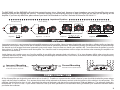
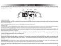
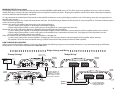
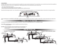
BMF CLASS D AMPLIFIERS
FEATURES
Class "D" Technology
Fully 1 Ohm Stable Operation
Military Spec Audiophile Grade Components
High Efficiency PWM Power Supply
-Multi-stranded power torroid
-Oversized torroidial core
MOSFET Input and Output Transistors
Oversized Capacitor Banks
Discrete Mount Power and Speaker Terminals
Variable Lowpass Electronic Crossover
Variable Subsonic Filter
RCA Preamp Output
-Variable HP/LP/Full crossover
Built in Bridging Module
-Master / Slave Selector
-0/180 Phase Selector
5 Way Protection Circuitry
Soft Remote On/Off Circuitry
Digital Subwoofer Level Control
Two Year Limited Warranty
SPECIFICATIONS
MODEL:
BMF1000D
BMF600D
RMS Power / 4 ohms @ 0.08% T.H.D.
2 ohms @ 0.4% T.H.D.
1 ohm @ 1 % T.H.D.
Efficiency / Typical
Worst Case
Bandwidth + 3dB
Signal To Noise
Damping Factor
Input Sensitivity
Input Impedance
Circuit Breaker / fuse
Dimensions
250W x 1
500W x 1
1000W x 1
86%
72%
10Hz – 250Hz
>90dB
200
240 mV – 6V
20K ohms
120 Amp
9.3”W x 2.1”H x 13”L
150W x 1
300W x 1
600W x 1
86%
72%
10Hz – 250Hz
>90dB
200
240mV – 6V
20k ohms
60 Am p
9.3”W x 2.1”H x 10.5”L
CROSSOVER
Low Pass
X-Over Slope
Variable Subsonic Filter
Preamp Crossover
Preamp output
Variable 50 – 250Hz
12dB
Variable 20 - 50Hz @ 12dB
Variable 50 – 250Hz
All specifications are with 12.5 volts DC. Typical output with 14.4 volts DC is 20% higher.
IMPORTANT
Please read all instructions before installation!
The quality of installation may affect the performance and reliability of your Crossfire product. If you have any doubts or questions regarding installation, you may
wish to contact your authorized Crossfire dealer. Remember to follow all wire and fuse requirements suggested in this manual. Warranty may void if proper
installation technique is not used.
OPERATION
Both the Crossfire BMF1000D and BMF600D are single channel, dedicated subwoofer amplifiers. Unlike other Crossfire BMF amplifiers, both these amplifiers operate
as a single channel, therefore one amplifier cannot be bridged by itself. Do not be fooled by the two sets of speaker outputs. Two outputs are provided strictly for
convenience and are paralleled internally on the circuit board of the amplifier. This means that if both outputs are used with one driver each, the amplifier sees the
same load as if the same two drivers are connected to only one output terminal.
In both diagrams, the
amplifier sees a 2 ohm load
PWR
PWR
PRT
PRT
-
+
-
+
+12
REM
-
GND
POWER
SPEAKER
+
-
+
+12
-
-
-
-
+
+
+
+
4 ohm subwoofer
4 ohm subwoofer
4 ohm subwoofer
REM
GND
POWER
SPEAKER
4 ohm subwoofer
BMF D AMPS
The BMF1000D and the BMF600D will reach their potential output into a 1ohm load. However, a lower impedance can send the amplifier into current
protection and possibly damage the circuitry. To prevent damage, use the following formulas to help you figure out the load you are placing on the
amplifier. If you have any difficulties, please contact your local Crossfire dealer or Crossfire's Technical Assistance at 562-483-8111.
Impedance Equations
Parallel Wiring
R
A
B
Series Wiring
R
BC
A
B
A
AxB
A + B= R
A + B= R
Equation
A
D
D
B C
R
R
Equation
Parallel Wiring, Dual Voice Coil
Series/Parallel Wiring Dual Voice Coil
Equation
(A + B) x (C + D)
A+B+C+D =R
(A x B)(C x D)
Equation (A + B) + (C + D) =R
MOUNTING
Appropriate mounting is very important for prolonged life expectancy of any amplifier. Select a location of applicable space that allows sufficient airflow and provides
protection from moisture. Keep in mind that an amplifier should never be mounted upside down. Upside down mounting will compromise heat dissipation through
the heatsink and will engage the thermal protection circuit much sooner. Excessive heat can shorten your amplifier's life. To maximize heat dissipation, be sure to
leave at least 2.5 inches of clearance around the amplifier. Fans should be used in correspondence with an escape duct for heat when mounting the amplifier in an
enclosed or restricted area.
Avoid slipping and scratching your new Crossfire amplifier by pre-drilling the mounting holes with either a 1/8" or 3mm diameter drill bit when using the screws
supplied in the accessory kit. Always investigate the mounting area thoroughly for electrical wires, vacuum lines, and brake or fuel lines before you start to prevent any
potentially expensive mistakes.
CROSS
OVER
LEVEL
REMOTE
SUB
SONIC
50 250
LPF
OUT
IN
HPF FULL LPF
O
Correct Mounting
Heat is lifted from the amplifier heatsink.
LOW IN
LINE OUT
MASTER
HPF FULL LPF
OFF ON SLAVE 0
INVERT
180
R
IN
LOW IN
LINE OUT
OFF ON SLAVE 0
180
MASTER
INVERT
Heat is trapped inside the amplifier, shortening
the life of the electronic components.
R
Incorrect Mounting
L
x
L
CROSS
OVER
LEVEL
REMOTE
SUB
SONIC
50 250
LPF
OUT
POWER CONNECTIONS
All Crossfire amplifiers are designed to work within 10.5 to 16 volts DC. Therefore, as a precaution the vehicle's electrical system should be checked for correct voltage
supply with the help of a voltmeter. First, connect the test leads of the voltmeter to the battery terminals with the ignition in of the vehicle in the off position. The
voltmeter should read no less than 12 volts. Next check the voltage of the battery with the engine running between 1500 and 2000 rpms. The voltmeter should now
read between 13.5 and 14.5 volts. If your vehicle's electrical is not up to these specifications, we recommend having it checked by an automotive mechanic before
you further the installation.
2
POWER WIRE & FUSE
The proper wire size is very important for an amplifier capable of these power levels. The following are the recommended fuse values and wire gauge for lengths up to
20ft.
Model
Wire
Fuse
BMF1000D
4awg.
100amp
BMF600D
8awg.
60amp
POWER
Power wire needs be connected directly to the battery using the wire requirements listed above. Never use the fuse box or any other wire as a source for the power for
an amplifier. Before you start, choose the easiest path to run the wire from the battery to the amplifier. Generally, try to keep the power wire on the driver's side of the
vehicle (See Signal Inputs & Outputs for explanation). Use the following rules for running the power cable through the vehicle:
1. Use grommets when passing the power wire through any metal wall of the vehicle.
2. Avoid sharp corners or sharp body parts that may easily cut through the insulation on the wire.
3. Avoid running the power wire over engine components and near heater cores.
4. Avoid the gas, brake and clutch pedals and their mechanisms.
5. Use an inline fuse to eliminate the risk of a fire caused by a short in your power wire.
6. Connect the fuse holder as close to the battery positive as possible.
Once the wire has been run, connect the wire to the battery terminal. As a precaution, leave the fuse out until all other wire connections are made.
GROUND
The wire used for ground should be of the same gauge as the power wire. Just make sure that you choose a different color (generally black) so that you don't reverse
the polarity at the amplifier terminals. Follow the rules below for connecting the ground wire properly:
1. Avoid using seat bolts, seatbelt bolts, and fender wells for ground.
2. Choose a metal area close to the amplifier that appears to be a good of ground, such as the floor.
3. Investigate the area you wish to use for electrical wires, vacuum lines, and brake or fuel lines.
Please note that if you are installing multiple high power amplifiers into the vehicle, you must upgrade the ground strap from the battery to the frame and the frame
to the body.
Directions:
1. Find a nut and bolt to fit the ring terminal you have chosen.
2. Drill a hole just large enough for the bolt to fit through at the source of ground.
3. Use either a wire brush or sandpaper to eliminate unwanted paint around the hole you have drilled as to supply a better contact for your ground.
4. Terminate the ground wire to the ring terminal and attach it to the bare metal using the nut and bolt. It is very important for this connection to be solid.
5. Spread silicon over the screw and bare metal to prevent rust and possible water leaks.
REMOTE TURN-ON
In between the power and ground of the amplifier is a remote turn-on terminal. This terminal must be connected to a switched +12 volt source to make the amplifier
operational. Typically, remote turn-on leads are provided at the head unit that will turn on and off the amplifier in correspondence with the source. This means you
will most likely have to remove the head unit from the dash to find the source +12V output wire.
Once the head unit is pulled from the dash, locate the remote turn on wire. The majority of vehicles will be using an after market head unit when using an amplifier.
These after market head units generally use a blue or a blue with white wire as the remote turn on for the amplifiers. However, when using a factory radio, the power
antenna wire should be as a turn on lead if applicable (colors will vary from make/model). Only if a lead is not available at the source, a switched +12 volt supply, such
as a toggle switch, should be applied.
Use a minimum of 18-gauge wire, preferably blue, to connect the amplifier to the head unit. If possible, route this wire along side of the power wire using the same
precautions. Connect the remote output of the head unit to the wire using a barrel connector or a mating terminal as required by the source unit. You can solder
these wires together, but be sure to use heat-shrink over the connection. Do not place the radio back into the dash yet.
3
SPEAKER OUTPUTS
WIRING
Due to the power output and the low frequency bandwidth of the Class "D" amplifiers, Crossfire recommends using a minimum of high quality 12 gauge speaker wire.
Consult your local dealer for their recommendations.
As with the power wires, use caution around sharp corners or body parts that may easily cut through the insulation on the wire. To connect the wire to the speaker,
strip off approximately ½" (12mm) of the insulation and terminate the wires using insulated speaker terminals (not supplied) or by soldering the connection to the
loudspeaker. Be sure that the polarity at the loudspeaker is correct.
CONNECTING THE WIRES
At this point, the power, ground, remote and speaker wires should be run to the general location of where the amplifier is to be mounted. If the wires are to be hidden
under the carpet, you now need to cut a slit for them to come through. To do this, place the amplifier in the location it is to be mounted to verify where the cuts need
to be made. Make sure that there will be not be a conflict with the mounting of the amplifier and the wires. Pull the wires through the slit to the terminals leaving
approximately 6" (150mm) of slack and cut the wires to an equal length. Strip off approximately ½" (12mm) of insulation from each wire. Insert the wires directly into
the terminal and tighten the set screw using a 3mm allen key. Make sure you have the polarity correct on both the power wires and the speaker wires. Check your
connections by giving the wires a slight tug.
SIGNAL INPUTS
Getting a clear signal from the head unit to the amplifier is very important. To achieve this, the proper signal cables must be used. Estimate the length of the cables
necessary. Take note that the cable manufacturers will probably not be the exact length necessary for your vehicle. If you are between sizes, purchase the longer cable.
You can always hide the extra wire.
Be aware off the differences in cable. Better RCA's usually have multiple layers of shielding and/or twisted pair wiring for better noise rejection. Consult your local
dealer for their recommendations.
LINE LEVEL INPUTS
Car environments are notorious for poorly insulated wires. This means that hiss, engine noise, and fan noise can easily be picked up through RCA cables if ran
incorrectly. To avoid picking up noise, run the RCA's away from large wire looms and electric fans if possible. And always make sure to position your patch cables away
from the power wire, preferably on the opposite side of the vehicle. As with the power wire, use caution around sharp corners of body parts that may easily cut
through the cables.
Located on the opposite side of the power terminals are three sets of line level (RCA) receptacles. Marked "LOW IN", these receptacles accept signal from the outputs of
the source unit via RCA patch cables. When connecting the signal cables, be sure the balance (left and right) stays consistent between the amplifier and head unit. The
cables should be marked for easy installation: red is right and black or white is left.
Once you have finished connecting the signal cables to the source unit, slide the head unit back into the dash location. Make sure that the head unit is in securely.
4
PEAMP FEATURES
The Crossfire BMF600D and BMF1000D have a tremendously powerful preamp section located on the panel opposite the power terminals. Included in this preamp
section are Lowpass Crossover for the amplifier, a switchable/variable Subsonic Filter, Preamp Output with Variable Crossover, a Digital Remote Level Control, and a built
in Bridging Module. These features can be used to improve your system quality an as well as make the amplifiers easier to use on a day to day basis. Please read the
following instructions carefully.
Line
Gain
control
level
inputs
LOW IN
Subsonic
Filter
Bridging
circuit
LINE OUT
MASTER
HPF FULL LPF
OFF ON SLAVE 0
R
L
INVERT
180
IN
CROSS
OVER
Preamp
output
w/crossover
LEVEL
REMOTE
SUB
SONIC
Remote
level
control
recepticle
50 250
LPF
OUT
Lowpass
crossover
LOWPASS CROSSOVER
Locate the rotary dial marked LPF. This is the LowPass Filter (crossover) for the amplifier. The lowpass crossover points are fully variable from 50Hz to 250Hz making
them ideal for subwoofers. Adjust this dial either to the recommended crossover frequency for the subwoofer or, more importantly, to a level where the subwoofer
blends well with the midrange.
*Note: Due to the limited frequency range of these Class D amplifiers, the crossover is always active.
SUBSONIC FILTER
The subsonic filter is used to reduce the amount of low frequency harmonics and/or subsonic noise picked up in audio systems. Both of these can be damaging to
subwoofer and possibly the amplifier. As well, harmonics and subsonic noise can cause the amplifier to pull excess power from your electrical system.
The subsonic filter on the BMF600D/1000D is selectable, ON/OFF, and variable from 20Hz to 50Hz. We make this switchable ON/OFF, for every system is different. For
most people it is desirable to have the filter on. However, if you have an outright SPL system, it may be beneficial to remove the subsonic filter because harmonics can
actually increase the sound pressure in many cases.
So what frequency should you set the subsonic at? For most applications it is desirable to leave this between 20Hz and 30Hz. If you are using a ported enclosure
designed for SPL, yet you are using the system on a daily basis, a higher filter frequency may be desired. This will allow the enclosure to be tuned higher and reduce the
chance of the woofer to becoming non-linear and destroying itself.
REMOTE LEVEL CONTROL
Optional to the BMF600D/1000D is the digital remote level control. This level control can be mounted in an area within reach from the driver's seat and can be used to
raise and lower the output level of the amplifier to the desired level. To connect this, run the provided cable from the remote to the amplifier. Plug the cable into the
receptacle on the preamp section of the amplifier marked "REMOTE". The remote control receives power directly from the amplifier so no extra wires need to be
connected.
LINE LEVEL OUTPUTS
The line level output is to be used as an easy solution to link multiple amplifiers together without the use of problematic RCA y-cables. The signal is buffered so that
there is no loss. Please note that the signal passing through these outputs is not affected by the gain control of the amplifier.
Included in the circuit of the line level output is an electronic crossover variable from 50Hz to 250Hz. This crossover is switchable from highpass, lowpass, and full range.
This allows the stereo system to remain flexible enough to be arranged in a numerous amount of ways. Please refer to the diagrams at the end of this section for
suggestions.
5
BRIDGING CIRCUIT (Invert output)
The bridging module can only be used when two pairs of either BMF600D or BMF1000D are used. This allows for the two amplifiers to be run in series to achieve
double the output. However, this does change the minimum impedance required to 2ohms. Bridging the amplifiers should only be done if the proper impedance
cannot be achieved with the amplifiers separated.
It is very important to set the Master/Slave control on the amplifier whether you are using the bridging module or not. If the settings are in the wrong position, the
amplifier may not work.
There are three settings for this control: Master 0, Master 180, Slave. Use the following to determine what position to set your amplifier in. For further reference, please
review the drawings following.
Master 0: this setting will maintain the same phase as the signal applied to it.
1. Use this setting if the amplifier is not bridged with another amplifier.
2. When bridging the amplifiers, use this setting only on the amplifier that is connected to the head unit.
Master 180: this setting will reverse the phase 180degrees of the signal input into the amplifier.
1. Use this setting if the amplifier is not bridged with another amplifier and the subwoofer(s) are out of phase with the satellite speakers in the vehicle.
2. When bridging the amplifiers, use this setting only on the amplifier that is connected to the head unit. Only apply this if the subwoofer(s) are out
of phase with the satellite speakers in the vehicle.
Slave: this setting limits the controls of the secondary amplifier in a bridged pair.
1. Use this setting only on the second amplifier in a bridged pair. All crossover, subsonic and level controls of this amplifier will be removed.
The amplifier set on one of the two Master settings will then control each of the preamp functions for both amplifiers.
HOW TO BRIDGE MY AMPLIFIERS
Bridging the two like amplifiers together is fairly easy. Please follow the following diagram to assure proper connections. If you are experiencing any difficulties,
please contact Crossfire's technical department at 562-483-8111.
Bridge Settings and Wiring
"Preamp Settings"
SUB LEVEL
CONTROL
DOWN
"Bridge Wiring"
Must be set to
Master 0 or 180
MASTER
Amplifier
From
Source
UP
LOW IN
LINE OUT
MASTER
HPF FULL LPF
OFF ON SLAVE 0
MASTER
Amplifier
INVERT
180
R
PWR
IN
PRT
L
CROSS
OVER
REMOTE
LEVEL
SUB
SONIC
50 250
LPF
OUT
-
+
SPEAKER
SLAVE
Amplifier
LOW IN
LINE OUT
MASTER
HPF FULL LPF
OFF ON SLAVE 0
INVERT
180
R
L
IN
CROSS
OVER
LEVEL
REMOTE
SUB
SONIC
50 250
LPF
Must be set
to Slave
+12
REM
GND
POWER
SLAVE
Amplifier
All P reamp functions of
the slave amplifier are
non-functional. T he Master
amplifier controls all level
and crossover functions.
PWR
PRT
-
OUT
+
SPEAKER
Speaker +
Do not use
this section
+
Speaker -
+
+12
REM
GND
POWER
It is very important that
a negative of each amplifier
is connected as shown
6
GAIN CONTROL
Located in the preamp section on the side panel of the amplifier is the gain control (marked level). This control allows you to match the input level of the amplifier to
the output level of your source unit or signal processor. Matching the input can be accomplished in three simple steps:
1. Turn gain control all the way down.
2. Turn on the source unit and adjust to 2/3 of max volume.
3. Adjust the gain control until desired volume is achieved without audible distortion
Remember that the gain control is not a volume knob. Ignoring the three steps above may leave you with damaged speakers and possibly a damaged amplifier.
LOW IN
LINE OUT
MASTER
HPF FULL LPF
OFF ON SLAVE 0
INVERT
180
R
IN
L
OUT
CROSS
OVER
LEVEL
SUB
SONIC
REMOTE
50 250
LPF
Gain
Control
If you are bridging the two BMF600D or BMF1000D's together, only the gain control on the "Master" amplifier is adjustable. Use the same three steps to adjust the
gain.
POWER AND PROTECTION
On the power and speaker panel of the amplifier are two LED's. These LED's indicate either power "on" or protection modes.
Green LED: This LED illuminates when the amplifier is powered up indicating
normal operation.
Red LED: This LED illuminates when the amplifier goes into protection. This
indicates a problem with the system in relation to the amplifier
connected to it.
SYSTEM EXAMPLES
Set crossover
to FULL
Example 1: Two way system
Set crossover
to HPF and adjust
crossover point
Subwoofer
LOW IN
LINE OUT
MASTER
HPF FULL LPF
OFF ON SLAVE 0
MASTER
HPF FULL LPF
OFF ON SLAVE 0
Example 2: Multi subwoofer system
Set crossover
to FULL
INVERT
180
IN
CROSS
OVER
LEVEL
REMOTE
SUB
SONIC
50 250
LPF
OUT
Subwoofer 2
INVERT
180
R
L
LINE OUT
R
L
LOW IN
Subwoofer 1
Set crossover
to FULL
IN
CROSS
OVER
LEVEL
REMOTE
SUB
SONIC
50 250
LPF
OUT
Satellite 1
Satellite 2
LOW IN
LINE OUT
MASTER
HPF FULL LPF
OFF ON SLAVE 0
R
L
HIGH IN LOW IN
L
R
LEVEL
BOOST
CROSSOVER
ON OFF
HPF FULL LPF
FREQ
R
POWER
L
50Hz 150Hz
INVERT
180
IN
CROSS
OVER
LEVEL
REMOTE
SUB
SONIC
50 250
LPF
OUT
Subwoofer 3
Source
Unit
LOW IN
LINE OUT
MASTER
HPF FULL LPF
Source
Unit
Set crossover
to FULL
OFF ON SLAVE 0
L
INVERT
180
R
IN
CROSS
OVER
LEVEL
REMOTE
SUB
SONIC
50 250
LPF
OUT
7