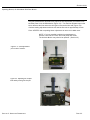
1
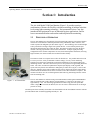
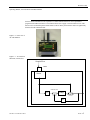
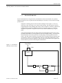
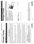
OPERATING MANUAL AIR-AIDE® MODEL AA-3500 DUST MONITOR Revision 02-09 EDC Part Number 42-004611 Environmental Devices Corporation 4 Wilder Drive, Bldg 15 Plaistow, NH 03865-2856, USA Phone: (603) 378-2112 Fax: (603) 378-2113 EDC innovative technologies for monitoring air quality Revision A.001 Operating Manual, Air-Aide Model 3500 Dust Monitor Licenses, Copyrights and Trademarks This documentation contains trade secrets and confidential information proprietary to Environmental Devices Corporation (EDC). The software supplied with the instrumentation, documentation and any information contained therein may not be used, duplicated or disclosed to anyone, in whole or in part, other than as authorized in a fully executed EDC End User License Agreement or with the express written permission of EDC. © 2000 Environmental Devices Corporation. All rights reserved throughout the world. The “EDC” logo and “Air-Aide” are registered trademarks of Environmental Devices ™ Corporation. DustComm Pro is a trademark of Environmental Devices Corporation. Other trademarks are the property of their respective holders. PAGE II Revision A.001 Operating Manual, Air-Aide Model 3500 Dust Monitor Safety Notice Repair of instrumentation supplied by Environmental Devices Corporation (EDC) should only be attempted by properly trained service personnel, and should only be conducted in accordance with EDC system documentation. Do not tamper with this hardware. High voltages may be present in all instrument enclosures. Use established safety precautions when working with this instrument. The seller cannot foresee all possible modes of operation in which the user may attempt to use this instrumentation. The user assumes all liability associated with the use of this instrumentation. The seller further disclaims any responsibility for consequential damages. Use of this product in any manner not intended by the manufacturer will void the safety protection provided by the equipment, and may damage the equipment and subject the user to injury. PAGE III Revision A.001 Operating Manual, Air-Aide Model 3500 Dust Monitor Warranty (U.S.) Unless otherwise agreed upon in writing by authorized personnel of Environmental Devices Corporation (EDC) and the purchaser, the following warranty shall be in force for equipment sold and operated in the United States of America. EDC warrants that the EDC-supplied equipment shall be free from defects in material or workmanship for a period of three hundred and sixty-five (365) days after the date of shipment. Subject to the conditions of this provision, EDC agrees to repair or replace, free of charge, any components of the equipment found to be defective in material or workmanship during the warranty period. Purchaser shall notify EDC of any detected defects and shall return any equipment believed to be defective to EDC, suitably insured and at the purchaser’s expense. In the event EDC determines the equipment returned for warranty correction is not defective within the terms of the warranty, purchaser shall be responsible for all costs of handling and return transportation. EDC’ sole responsibility under the warranty shall be, at EDC’s option, to either repair or replace any component that fails during the warranty period due to a defect in workmanship and/or material, provided purchaser has promptly reported same to EDC and EDC has, upon inspection, found such components to be defective. The above warranty is contingent upon the proper use of the equipment (i.e., operation and maintenance in accordance with the procedures set forth in the provide operation manual(s) and does not cover equipment that has been modified without EDC’s approval or subjected to abuse or unusual physical or electrical stress. This warranty does not cover any optional personal computer equipment or operating system software supplied with the equipment beyond the warranty period provided by the manufacturer of the computer or software. The customer is responsible for obtaining a local, third-party service agreement for computer service requirements beyond the warranty term of the computer. THE ABOVE IS A LIMITED WARRANTY AND IS THE ONLY WARRANTY MADE BY EDC. EDC DISCLAIMS ALL OTHER WARRANTIES, EXPRESS OR IMPLIED, INCLUDING ALL WARRANTIES OF MERCHANT ABILITY AND FITNESS FOR A PARTICULAR PURPOSE. THE STATED EXPRESS WARRANTY IS IN LIEU OF ALL LIABILITIES OR OBLIGATIONS OF EDC FOR DAMAGES ARISING OUT OF OR IN CONNECTION WITH THE DELIVERY, USE OR PERFORMANCE OF THE EQUIPMENT. IN NO EVENT SHALL EDC BE LIABLE FOR ANY SPECIAL, CONSEQUENTIAL, EXEMPLARY OR INDIRECT DAMAGES EVEN IF IT HAS BEEN ADVISED OF THE POSSIBILITY OF SUCH DAMAGES. PAGE IV Revision A.001 Operating Manual, Air-Aide Model 3500 Dust Monitor Table of Contents SECTION 1: INTRODUCTION .................................................................................... 1-1 1.1. 1.2. 1.3. 1.4. Principle of Operation .................................................................. 1-1 System Overview ........................................................................ 1-3 Distinctive Features ..................................................................... 1-4 Organization of Manual ............................................................... 1-5 SECTION 2: OPERATING PARAMETERS ................................................................ 2-1 2.1. 2.2. Hardware Configuration ............................................................. 2-1 Unit Specifications ...................................................................... 2-2 2.3. 2.3.1. 2.3.2. 2.3.3. Turning Instrument On and Off .................................................. 2-3 Supply Voltage …………………………………………………..2-4 Checking Battery Status..... ................................................... 2-5 Charging the Battery .............................................................. 2-5 2.4. 2.5. 2.5.1. 2.5.2. 2.5.3. 2.5.4. 2.5.5. 2.5.6. Display and Keypad Conventions………………………………….2-7 Setting Up the Monitor for Sampling……………………………...2-8 Inlet Installation ...................................... ……………………..2-8 Setting Time and Date ........................................................ 2-10 Setting Alarm Level ............................................................. 2-11 Selecting Particle Size Range ............................................. 2-11 Begin Sampling ................................................................... 2-12 Turning Off Auto Zero…………………………………………2-12 SECTION 3: INSTRUMENT CALIBRATION AND MAINTENANCE ............... 3-1 3.1. 3.2. 3.3. 3.4. 3.5. 3.6. Flow Rate Check ......................................................................... 3-1 Cleaning the Optics ..................................................................... 3-3 Manual Zero Check ..................................................................... 3-4 Auto Zero Check ......................................................................... 3-5 Span Check ................................................................................. 3-5 Performance Check ..................................................................... 3-7 SECTION 4: SYSTEM OPERATION………………………………………………4-1 4.1 4.2. 4.3. 4.4. 4.5. Operating Considerations……….……………………………………4-1 Initiating Data Collection……………………………………………...4-1 Run Screen.................................................................................... 4-3 Ending Data Collection……………………………………… ……..4-4 Location Codes………………………………………………………… ..4-4 PAGE V Revision A.001 Operating Manual, Air-Aide Model 3500 Dust Monitor 4.6. Erasing the Data Storage Buffer…………………………………4-4 SECTION 5: REVIEWING STORED DATA ...................................................... 5-1 5.1. 5.2. Summary Statistics……………………………………………….5-1 Reviewing Stored Data…………………………………………..5-2 SECTION 6: PC SOFTWARE AND DATA RETRIEVAL…….…………………..6-1 6.1. 6.2 6.3 6.4 6.5 6.6 6.7 6.8 6.9 6.10 6.11 6.12 6.13 Introduction to DustComm Pro Software………………….…….. 6-1 Installing DustComm Pro Software…..……………………….…..6-2 Loading DustComm Pro Software…..……………………….……6-3 Menu Selections……………………….…………………………....6-4 File Menu Commands….…….……………………………………..6-5 Downloading Data……………..……………………………………6-7 DustComm Pro Window.…………………………………..……….6-9 Translating Data in ASCII Text File………………………..….…6-12 Generating a Plot………………...………………………………..6-13 Data Plot Menu Selections….……………………………………6-14 Editing Title…………………………………………………………6-16 Applying a Correction Factor……………………………………..6-17 Inability to Download………………..…………………………….6-18 APPENDIX A: LISTING OF SCREENS…………………………………………….A-1 APPENDIX B: LISTING OF CONSUMABLES AND SPARE PARTS……………B-1 PAGE VI Revision A.001 Operating Manual, Air-Aide Model 3500 Dust Monitor This page left intentionally blank. PAGE VII Revision A.001 Operating Manual, Air-Aide Model 3500 Dust Monitor Section 1: Introduction The Air-Aide Model 3500 Dust Monitor (Figure 1-1) provides a unique combination of features for flexible, real-time monitoring of ambient articulate levels using light-scattering technology. Environmental Devices Corp. has introduced this equipment for use in industrial hygiene applications, and for lower-concentration indoor and outdoor ambient particulate monitoring. 1.1 PRINCIPLE OF OPERATION The Air-Aide Monitor uses the principle of near-forward light scattering of an infrared beam to measure the concentration of airborne particulate matter continuously and in real time, with results expressed in milligrams per cubic meter (mg/m3). This technology uses an infrared light source positioned at 90-degree angle from a photo detector. As the airborne particles pass through the infrared beam, they scatter the light. The amount of light received by the photo detector is directly proportional to the aerosol concentration. A unique signal processing configuration in the monitor compensates for noise, drift and temperature fluctuation, allowing high resolution, low detection limits and excellent baseline stability. The monitor is built in a compact form to allow for flexible use. It is portable and can be used as a survey tool in a variety of industrial or indoor settings, or in city-center monitoring applications in which space limitations preclude the installation of conventional ambient air monitoring stations. The unit’s alarm can be preset to alert personnel of approaching threshold limits. The 4-line, 20-character alphanumeric liquid crystal display (LCD) is backlit, and reports real-time particle concentrations in milligrams per cubic meter (mg/m3) at one-second intervals. Statistics such as time-weighted average (TWA), short-term exposure limit (STEL), and maximum and minimum levels can be viewed as soon as data collection is complete. The monitor also allows users to scroll through stored data and to tag monitoring locations with an auto-incrementing code. The Air-Aide Monitor is calibrated using Arizona Road Dust (ARD) against NIOSH Method 0600 for respirable dust (with a diameter of approximately 3.5 microns) to an accuracy of approximately +10%. For monitoring applications in which a large part of the particulate matter is larger than 5 microns in diameter, the user can select a calibration factor or the larger particle size range. Figure 1-1. Air-Aide Monitor An RS232 port allows internally stored data to be downloaded to the PC-based DustComm Pro software provided with the unit for detailed graphing and analysis. The SECTION 1: INTRODUCTION PAGE 1-1 Revision A.001 Operating Manual, Air-Aide Model 3500 Dust Monitor Software allows information to be exported in a comma-delimited format for use in spreadsheet programs such as Microsoft Excel. The software allows user to apply a correction factor to Air-Aide data for cases in which the particle characteristics such as density and refractive index are significantly different from the calibration dust. Figure 1-2. Front view of Air-Aide Monitor. Figure 1-3. Air-Aide flow Schematic, normal flow. Sample Flow Inlet Sensor Solenoid value Filter Pump Solenoid value Filter SECTION 1: INTRODUCTION PAGE 1-2 Revision A.001 Operating Manual, Air-Aide Model 3500 Dust Monitor 1.2. SYSTEM OVERVIEW The Air-Aide Monitor has a long-life battery and transformer for both 120 and 240 VAC operation, making it possible for users to operate the unit autonomously for five hours, or at a fixed site for longer periods of time. Sampled air containing particles enters the monitor through its inlet (Figures 1-3 and 1-4), which may or may not contain a size-selective foam cartridge. The unit operates in its total suspended particle (TSP) sampling mode when no insert is installed. Alternately, Impactors are available for PM-1.0, PM-2.5, and PM-10 particle size cut points (Figure 1-5). These are designed for operation at a sample flow rate of 2 l/min, which is maintained by a long-life pump. After passing through the inlet, the sample stream proceeds through the optical sensor, where particulate measurement occurs using infrared, near-forward light scattering. An in-line pump filter downstream of the sensor protects the vacuum pump by removing particles from the airflow. This filter must be replaced on a periodic basis to maintain the proper operation of the Air-Aide unit. (Section 3.5) An internal pump creates the vacuum that maintains the 2 l/min flow rate for the size-selective impactors. The air stream exits the monitor at the opposite end from the intake to prevent air-monitoring data contamination. Figure 1-4. Air-Aide flow Schematic, auto zero flow. Purge Flow Inlet Sensor Filter Pump Filter SECTION 1: INTRODUCTION PAGE 1-3 Revision A.001 Operating Manual, Air-Aide Model 3500 Dust Monitor DISTINCTIVE FEATURES 1.3. The Air-Aide Model 3500 Dust Monitor offers a number of features to provide superior data quality, ease of use and flexibility to the end user. Following is a partial list of distinctive features: SECTION 1: INTRODUCTION Resolution and stability (with automatic re-zeroing): - 0.001 mg/m3 resolution - Stability at constant temperature (1 σ ): +0.005 mg/m3 per hour - Temperature stability ( 1 σ): +0.0025 mg/m3 per oC. Active sample flow of 2 l/min using a long-life brush less pump In addition to TSP (no size-selective inlet), particle size separation at PM-1.0, PM-2.5, and PM-10 through the use of impactors Downloading of stored data through an RS232 port. PC-based software is supplied to download and graph stored data. Optional wireless data transfer Selection of different built-in calibration factors for fine and coarse particulate matter Location codes, user-defined audible alarm, capability to connect alarm to compute or other device, security code restricts unauthorized use Eight-hour battery life (rechargeable battery). The monitor runs on AC or DC power, or from a car/motor battery. PAGE 1-4 Revision A.001 Operating Manual, Air-Aide Model 3500 Dust Monitor 1.4. ORGANIZATION OF MANUAL This manual is divided into seven sections and two appendixes, which discuss different topics. The first sections discus the configuration and proper operation of the Air-Aide Monitor, while the later sections cover operation and data retrieval. The user should read and understand earlier sections before operating the instrument on a routine basis. The following list provides an overview of the topics handled in each section of the manual. Section 1: Introduction This section introduces the user to the principles of operation and unique features of the Air-Aide Monitor. Section 2: Operating Parameters This section describes the steps involved in starting the monitor and configuring its operating parameters. Section 3: Instrument Calibration and Maintenance This section contains instructions for checking the flow rate, zero baseline and span of the monitor. It also describes the steps involved in cleaning the optical sensor and replacing the in-line filters. Section 4: System Operation This section provides a list of operating guidelines and describes the steps involved in collecting data and setting location codes. Section 5: Reviewing Stored Data The Air-Aide Monitor stores field data internally and displays this information in summary and detailed form on its the four-line LCD display. This section describes the commands that exercise this function. Section 6: PC Software and Data Retrieval This section explains how to install and operate computer software to download stored information from an Air-Aide Monitor. It also describes how to export collected data to a spreadsheet for further evaluation. Appendix A: Listing of Screens This appendix includes all of the major screens that make up the Air-Aide Monitor’s user interface. Sections of this appendix are referenced several times throughout the manual. Appendix B: Listing of Consumables and Spare Parts This appendix lists consumable items and spare parts for the Air-Aide Monitor. SECTION 1: INTRODUCTION PAGE 1-5 Revision A.001 Operating Manual, Air-Aide Model 3500 Dust Monitor Section 2: Operating Parameters This section covers the steps involved in turning the monitor on and off, and selecting the desired operating parameters for its operation. 2.1. HARDWARE CONFIGURATION EDC supplies the Air-Aide Monitor with the following standard components listed below. If you are unpacking a new instrument, ensure that these parts are included in packaging: 1 1 1 1 1 1 1 Air-Aide Monitor (Figure 2-1) Universal Transformers for 110 and 220 VAC (Figure 2-2) Impactor Sleeve (Impactors are not included) Impactors are purchase as optional accessories Adjustment tool for flow rate Flow audit meter and adapter DustComm Pro software package for Windows 9-to-9 pin RS232 cable for connection to a PC Figure 2-2: Universal transformer for 110V and 220V Figure 2-1: AA-3500 Kit Comes Complete with: Battery Charger, Computer Cable & DustComm Pro Software, Flow Meter & Adjustment tool, Impactor Sleeve, & Instruction Manual SECTION 2: OPERATING PARAMETERS PAGE 2-1 Revision A.001 Operating Manual, Air-Aide Model 3500 Dust Monitor 2.2. UNIT SPECIFICATIONS The Air-Aide Monitor’s dimensions are 3 inches by 6 inches by 9 inches. It weighs 5 pounds with its rechargeable battery installed. Do not immerse the unit in water or allow it to be subjected to precipitation such as rain or snow. If the monitor will be operated in an environment where it is raining or snowing, be sure to provide shelter o o for the unit. The monitor may be operated in temperatures ranging from 0 C to 50 C and in humidity levels up to 95%, noncondensing. The unit may be stored in 0 o temperatures ranging from –20 C to 60 C. SECTION 2: OPERATING PARAMETERS PAGE 2-2 Revision A.001 Operating Manual, Air-Aide Model 3500 Dust Monitor 2.3. TURNING INSTRUMENT ON AND OFF A new Air-Aide Monitor or a unit whose battery has a low charge may require recharging prior to DC operation. Even with a low battery charge, the monitor can be operated from an AC power source using one of the transformers supplied with the unit. (Section 2.2.1.) The monitor can also be operated from a car/motor battery with a back pate auxiliary power attachment (38-005553). (Section 2.2.1) In the following text, keystroke instructions are designated by angle brackets (<>), for example: <ON/OFF>. Figure 2-6 (Left). Title screen. Figure 2-7 (Right). Main menu. SECTION 2: OPERATING PARAMETERS ** EDC** Air-Aide™ Dust Monitor Ver 4.4 02/09 -Sample Record Playback Special Functions Cancel PAGE 2-3 Revision A.001 Operating Manual, Air-Aide Model 3500 Dust Monitor With power supplied to the monitor either from its internal battery, an AC or DC power source or a car/motor battery, press <ON/OFF> to turn on the device. The Title screen (Figure 2-6) appears after power up. Press <ENTER> to display the Main menu (Figure 2-7). Pressing <ON/OFF> again causes the monitor to turn off. This command works in most of the screens displayed by the monitor. Figure 2-8. (A) P5 power input connector on back panel of monitor/battery pack. A A 2.3.1. SUPPLY VOLTAGES The Air-Aide Monitor has a P5 power input connector on its back panel that is part of the battery pack (Figure 2-8). This connector accepts an input voltage of 9 VDC (1 amp current) to operate the instrument and recharge the battery. The instrument contains a 6 VDC lead acid rechargeable battery with a 3.6 amp-hour storage capacity. This battery will not affect the unit’s data memory storage and you do not need to completely drain the battery before charging it. However, the battery will grow stale easily if used infrequently. If the monitor is not used on a daily basis, turn the unit on and operate it for 10-15 minutes every 3-4 weeks to maintain proper battery operation. A fully charged, new battery used at room temperature will operate a monitor for 8 hours. SECTION 2: OPERATING PARAMETERS PAGE 2-4 Revision A.001 Operating Manual, Air-Aide Model 3500 Dust Monitor If desired, the user may use the analog output jack plug to connect a voltmeter or other analog device to measure Air-Aide’s signal output 2.3.2.CHECKING BATTERY STATUS To check the status of the monitor’s internal battery, choose the following selections from the Main menu (Figure A-7): Special Functions System Options Battery Status The Battery Level screen displays the charging level of the unit’s battery in VDC. If the battery is fully charged, this reads 6.50 VDC or higher. A depleted battery will show a charge level of 5.95 VDC or lower. A low voltage indicates that the battery should be recharged. 2.3.3. CHARGING THE BATTERY The battery of the Air-Aide Monitor is recharged while inside the instrument. Recharging time is approximately 20 hours. If you connect the transformer to the battery (while it is installed in the unit) and begin sampling, the transformer will power the unit. The battery will not recharged under these circumstances, but it will maintain its charge level. To recharge a battery, connect the transformer to the battery input connector on the back panel of the monitor (Figure 2-8). . SECTION 2: OPERATING PARAMETERS PAGE 2-4 Revision A.001 Operating Manual, Air-Aide Model 3500 Dust Monitor 2.4. DISPLAY AND KEYPAD CONVENTIONS The Air-Aide Monitor’s user interface is accessed by the four keys on the unit’s front panel. The monitor’s keys play the following roles: <ON/OFF> The <ON/OFF> key turns the instrument on and off from most screens of the user interface. < > The < > is the <ENTER> key that selects items from menus and exits from screens and processes that do not have a cancel option. In addition, pressing <ENTER> causes the cursor to advance one character to the right when marking numerical entries. < >The < > key is used to scroll upward in a variety of situations. This key moves the cursor among options in menus and from screen to screen when scrolling through statistics or stored information. It also is used to increase values when making numerical entries. < > The < > key is used to scroll downward in a variety of situations. This key moves the cursor amount options in menus and from screen to screen when scrolling through statistics or stored information. It also is used to decrease values when making numerical entries. SECTION 2: OPERATING PARAMETERS PAGE 2-7 Revision A.001 Operating Manual, Air-Aide Model 3500 Dust Monitor 2.5 . SETTING UP THE MONITOR FOR SAMPLING Before using the Air-Aide Monitor, make sure the unit’s inlet and operating parameters are properly set up. The following items should be checked prior to making a set of measurements: Inlet Installation The impactor sleeve must be installed in the Air-Aide Monitor’s inlet for total suspended particulate (TSP) monitoring. For PM-1.0, PM-2.5, or PM-10 measurements, the appropriate impactors must be installed into their matching inlets. (Section 2.5.1) Time and Date For proper record keeping, the system’s time and date must be correct. (Section 2.5.2) Alarm Level If the unit’s audible alarm will be used, the alarm level must be set before monitoring. (Section 2.4.3) Particle Size Range The Air-Aide Monitor’s optical sensor has a greater sensitivity to particles of approximately 2.5 m diameter than particles between 5 and 10 m diameter. The appropriate selection for particle size range, fine or coarse, must be made before monitoring. (Section 2.5.4) Manual/Auto Zero The monitor’s manual/auto zero capability eliminates shifts in the monitor’s zero baseline associated with temperature changes of the sampled air stream. The monitor automatically performs an auto zero every 15 minutes. If desired, the user may turn off the auto zero function. (Section 2.5.6) X Do not attempt to sample TSP without the impactor sleeve installed on the monitor. If the insert holder is not properly installed, light entering the monitor’s entrance may bias the data. SECTION 2: OPERATING PARAMETERS 2.5.1. INLET INSTALLATION The user can configure the Air-Aide Monitor’s inlet system to sample any of the following particle size ranges: TSP Total suspended particulate (TSP) monitoring involves the sampling of as much suspended particulate matter as possible. For this application, install the impactor sleeve over the entrance to the monitor. Do not install any impactors into the impactor sleeve for TSP monitoring. PAGE 2-8 Revision A.001 Operating Manual, Air-Aide Model 3500 Dust Monitor PM-1.0 To sample particulate matter smaller than approximately 1.0 m in diameter, install the impactor sleeve over the entrance to the monitor. Insert the PM-1.0 impactor into the impactor sleeve. PM-2.5 To sample particulate matter smaller than approximately 2.5 m in diameter, install the impactor sleeve over the entrance to the monitor. Insert the PM-2.5 impactor into the impactor sleeve. PM-10 To sample particulate matter smaller than approximately 10 m in diameter, install the impactor sleeve over the entrance to the monitor. Insert the PM-10 impactor into the impactor sleeve. NOTE: Perform a manual zero check (Section 3.3) before operating the monitor. SECTION 2: OPERATING PARAMETERS PAGE 2-9 Revision A.001 Operating Manual, Air-Aide Model 3500 Dust Monitor 2.5.2. SETTING TIME AND DATE To check the current time and date maintained by the monitor’s internal clock, choose the following selections from the Main menu (Figure A-6): Special Functions Date/Time View Date/Time If the current time or date is not correct, change them by choosing the following selections from the Main menu (Figure A-6): Special Functions Date/Time Set Date/Time Press < > and < > to increase and decrease values in the time, date and day fields, and <ENTER> to move from one digit or field to another (Figure A-6). After selecting the desired day and then pressing <ENTER>, the monitor allows the user to confirm (“Set Date/Time”) or cancel (“Cancel”) the entry. SECTION 2: OPERATING PARAMETERS PAGE 2-10 Revision A.001 Operating Manual, Air-Aide Model 3500 Dust Monitor 2.5.3. SETTING ALARM LEVEL If the monitor’s audible alarm will be used during measurements, the triggering alarm level must be set before beginning measurements. Set the alarm level by choosing the following selections from the Main menu (Figure A-6): Special Functions Set Alarm Press < > and < > to increase and decrease digits in the concentration field, and <ENTER> to move from one digit to another (Figure A-6). Because the monitor’s alarm can be difficult to hear over the noise of its pump, the user may want to connect the units’ alarm to a blinking light or other device, to indicate more clearly to the user when the alarm has been triggered. After attaching circuitry to the alarm output jack plug, the user can insert the plug into the port (Figure 2-15) on the side of the unit (Figure 2-16). The unit provides 50-75 mA, 5 VDC output for alarm circuitry. This output is triggered only when the alarm is set or initiated. If the alarm is not set, the unit will not provide any output out this port. 2.5.4. SELECTING PARTICLE SIZE RANGE In many monitoring applications, the majority of the particulate mass suspended in ambient air is comprised of particles smaller than 5 m in diameter. However, in some situations, a large part of the mass is made up of particles larger than 5m in diameter. Because the Air-Aide Monitor’s optical sensors are more sensitive to smaller particle SECTION 2: OPERATING PARAMETERS PAGE 2-11 Revision A.001 Operating Manual, Air-Aide Model 3500 Dust Monitor Diameters than larger ones, the unit applies a multiplicative factor of 1.75 if the user indicates that most of the particulate mass is contained in larger particles. Select the appropriate particle size range by choosing the following selections from the Main menu (Figure A-8): Special Functions System Options Extended Options Size Select Press < > and < > to point to the desired size range, and <ENTER> to make the proper selection (Figure A-8). Two additional methods exist for adjusting the monitor’s data for differences between the Arizona Road Dust used to calibrate the Air-Aide and the particulate matter actually being monitored: For a continuous adjustment of the data as monitoring takes place, the user can alter the factor entered in the monitor’s span check routine. (Section 3.4) For an after-the-fact adjustment of collected data, the user can apply a custom correction factor in the provided DustComm software to data downloaded from the monitor to a personal computer. (Section 6) 2.5.5. BEGIN SAMPLING Ensure that the monitor is calibrated to the environment that it will be sampling. (Section 3.3) Before sampling, operate the monitor in the environment that it will be sampling for 5 minutes. Perform a manual zero check (Section 3.3) and then begin sampling. 2.5.6. TURNING OFF AUTO ZERO If desired, the user may turn off the monitor’s auto zero function. Turn off the auto zero function by choosing the following section from the Main menu (Figure A-8): Special Functions System Options Extended Options Auto Zero No With the cursor pointing to “No”, press <ENTER> to turn off the auto zero function (Figure A-8). SECTION 2: OPERATING PARAMETERS PAGE 2-12 Revision A.001 Operating Manual, Air-Aide Model 3500 Dust Monitor Section 3: Instrument Calibration and Maintenance This section describes the procedures involved in checking the monitor’s flow rate, zero and span settings. It also explains the steps for cleaning the optical sensor and replacing in-line filters. 3.1. FLOW RATE CHECK Flow rate is factory set to 2 LPM. Check the system flow rate periodically to ensure that it is close to the 2 l/min operational rating of the PM-1.0, PM-2.5 and PM-10 impactors. Connect an optional flow meter to the Air-Aide Monitor’s entrance (Figure 3-1). Choose the following selections from the Main menu to begin operating the monitor’s pump: Sample/Record Short Term 2 Second Continuation No Sample/Rec Figure 3-1 (Left). Flow meter connected to the Air-Aide Monitor using adapter for flow audit and flow audit tube. (Optional) SECTION 2: OPERATING PARAMETERS PAGE 3-1 Revision A.001 Operating Manual, Air-Aide Model 3500 Dust Monitor Using the potentiometer adjustment tool, adjust the flow adjustment pot located on the left-hand panel of the Air-Aide Monitor (Figure 3-2). Turn the flow adjustment pot to the left to decrease the flow rate and to the right to increase the flow rate (Figure 3-3). Continue making adjustments with the tool until the flow rate is approximately 2 l/min. Press <ENTER> after completing these adjustments to return to the Main menu. NOTE: If it is not possible to adjust the potentiometer to Achieve a flow rate of 2 l/min, the in-line pump filter inside The Air-Aide Monitor may need to be replaced. (Section 3.5) Figure 3-2. Flow adjustment pot on side of monitor. Figure 3-3. Adjusting the sample flow rate by turning the trim pot. SECTION 2: OPERATING PARAMETERS PAGE 3-2 Revision A.001 Operating Manual, Air-Aide Model 3500 Dust Monitor 3.2. CLEANING THE OPTICS AND INTERNAL FILTER REPLACEMENT Annual calibration and optical cleaning is recommended at the factory. Please consult [email protected] SECTION 2: OPERATING PARAMETERS PAGE 3-3 Revision A.001 Operating Manual, Air-Aide Model 3500 Dust Monitor 3.3. MANUAL ZERO CHECK EDC advises users to conduct frequent manual zero checks to confirm the Air-Aide Monitor’s measurement baseline. This check should be performed frequently and should generally be done prior to beginning a new set of measurements, or if the monitor is subjected to large changes in ambient temperature. When the user initiates a manual zero check, the monitor runs the baseline check for 100 seconds. NOTE: If the Air-Aide Monitor is operated infrequently, run it for 1 to 2 minutes before conducting a manual zero check. (Sections 4.2 to 4.4) To prepare the Air-Aide Monitor for a manual zero check, ensure that the inlet system being used for concentration measurements is installed on the monitor’s entrance (Figure 2-13). Then choose the following selections from the Main menu to begin the manual zero check (Figure A-8): Special Functions Manual-Zero System Options Extended Options Calibration After confirming that the user wishes to perform a manual zero check, the monitor automatically executes the steps necessary to reestablish the baseline. NOTE: For consistent results, perform the manual zero Check whenever switching between battery and AC-transformer operation. SECTION 2: OPERATING PARAMETERS PAGE 3-4 Revision A.001 Operating Manual, Air-Aide Model 3500 Dust Monitor 3.4. AUTO ZERO CHECK To confirm the Air-Aide Monitor’s measurement baseline during sampling, the monitor does an auto zero every 15 minutes during sampling. 3.5. SPAN CHECK EDC recommends that span checks be performed on a weekly basis in high3 Concentration environments (more than 1 mg/m ) and on a monthly or less frequent interval for Air-Aide Monitors used in less-polluted environments. A manual zero check should be performed prior to executing a span check. NOTE: Performing a span check erases the internal data storage buffer in which instrument results are stored. Set up the monitor for a span check by installing the span calibration insert into the entrance to the Air-Aide Monitor (Figure 3-8). A positioning pin on the insert will fit into a small mounting hole located at the edge of the opening. Make sure that the pin is in the proper location and that the insert is firmly in place. Once the insert is installed, you will see its calibration value displayed on the flat end of 3 the insert. This value is typically between 1 and 16 mg/m . This accessory is instrument specific meaning two instrument will not give exactly the same “k” value. SECTION 2: OPERATING PARAMETERS PAGE 3-6 Revision A.001 Operating Manual, Air-Aide Model 3500 Dust Monitor NOTE: Be careful not to damage the span calibration insert and make sure that it is returned to its protective plastic tube immediately after each use. Choose the following selections from the Main menu to initiate a span check (Figure A-8): Special Functions System Options Sensor Calibrate Figure 3-8. Installing the span calibration insert into the Air-Aide Monitor Extended Options Calibration A Warning/Confirmation screen will then appear. The display asks the user to confirm “Yes” or “No” to “Sensor Calibrate?” and warns the user that previously stored data will be lost. The monitor then displays the Sensor Calibration screen (Figure A-8). The calibration value of the span calibration insert should match the concentration shown on the Sensor Calibration screen to within 10%. Press < > and < > to increase and decrease the value of the scale variable, respectively. Increasing the value of the scale variable will increase the displayed concentration, and decreasing the scale variable will lower the concentration. Press < > and < > to and decrease the scale value more rapidly. Record the concentration. Because the monitor is a light scattering device, the concentration may fluctuate somewhat due to mechanical noises and other vibrations. Repeat the span check two more times, each time recording the concentration. Take the average of the three-recorded concentrations. The average concentration should be within 10% of the insert’s calibration value NOTE: If the concentration displayed by the Air-Aide Monitor is significantly different from the value shown on the span calibration insert, perform another manual zero check (Section 3.3) and then conduct the span check again. If a user determines that their Air-Aide Monitor consistently under or overestimates the concentration of particulate matter, the scale variable can be adjusted by a corresponding multiplicative factor to better match the conditions at that location. NOTE: Always run a manual zero check (Section 3.3) after completing a span check. SECTION 2: OPERATING PARAMETERS PAGE 3-7 Revision A.001 Operating Manual, Air-Aide Model 3500 Dust Monitor 3.6. PERFORMANCE CHECK EDC advises users to conduct periodic performance checks to confirm the Air-Aide Monitor’s measurement baseline. This is to check the monitor’s performance characteristics on the bench. To prepare the Air-Aide Monitor for a performance check, install optional zeroing filter and the zero filter adapter over the inlet system being used for concentration measurements (Figure 3-12) These are optional accessories. Then initiate a sampling run for 8 hours (Section 4) using AC transformer. Be sure to set the particle size range for F (fine). Once this has been completed, download the results into a personal computer (PC) with the DustComm Pro software program (Section 5). The plotted results should measure 3 between 0 and 0.015 mg/m over an averaging time of 1 minute. Figure 3-12. Zero filter and adapter mounted over the inlet system for a performance check. SECTION 2: OPERATING PARAMETERS PAGE 3-8 Revision A.001 Operating Manual, Air-Aide Model 3500 Dust Monitor This page left intentionally blank. SECTION 2: OPERATING PARAMETERS PAGE 3-9 Revision A.001 Operating Manual, Air-Aide Model 3500 Dust Monitor Section 4: System Operation This section describes how to use the Air-Aide Monitor for collecting real-time particle concentration data. Review the information presented in Sections 2 and 3 before using the unit in the field. 4.1. OPERATING CONSIDERATIONS As with any monitoring tool, users should be ware of the Air-Aide Monitor’s limitations before operating the device in the field. The major considerations in operating the unit are as follows: The ambient temperature must be between 0 and 50 C (32 and 120 F). Moisture in the air should not be allowed to condense between the sample stream and the unit. This generally means that the relative humidity must be lower than 95%, non-condensing. However, if you must use the monitor in a warm, humid environment, and if the unit I stored n an air-conditioned area, you may need to give the unit some time to acclimate to the sampling environment prior to use. If you will use the monitor in an environment that differs significantly in temperature from the area in which you store the unit, EDC strongly recommends that you calibrate the unit to the new conditions before collecting data. After calibrating the monitor, EDC also recommends that you perform a manual zero check in the new conditions. o o o o 4.2. INITIATING DATA COLLECTION Before you begin sampling, conduct a performance check to verify the unit’s measurement baseline (Section 3.7). Select the following entries from the Main menu to begin data collection (Figure A-2): Sample/Record Short or Long Term Ave/Storage Intervals SECTION 2: OPERATING PARAMETERS Indicates that sample collection and data logging are being initiated. Select short-term or long-term data averaging and storage intervals. Select 2, 4 or 10 seconds for short-term data averaging/storage, and 1, 10 or 30 minutes for long-term data averaging/storage. PAGE 4-1 Revision A.001 Operating Manual, Air-Aide Model 3500 Dust Monitor Data Storage Type Select Overwrite or Continuation. If the user selects Overwrite, the unit will confirm whether the user wants to select Overwrite, which erases all currently stored data. If the user selects Continuation, the monitor appends the currently stored data with new records and assigns the next sequential location code to the new set of information. Alarm Status Select Sample/Rec with or without implementing the user-defined alarm capability. If the user chooses to use the monitor’s alarm function, an audible alarm will sound whenever the particulate concentration exceeds a predefined level. (Section 2.4.3) The monitor will momentarily display the Preparing Compensation screen before proceeding to the Run screen. This indicates that the unit is automatically compensating for temperature changes in the sampled air stream to minimize shifts in the monitor’s zero baseline. This feature is automatic and cannot be turned off. Figure 4-1. Run screen. Loc: 005 run I Date: WED 02-JAN-09 Time: 21:26:38 3 Conc: F 0.073 mg/m SECTION 2: OPERATING PARAMETERS PAGE 4-2 Revision A.001 Operating Manual, Air-Aide Model 3500 Dust Monitor 4.3. RUN SCREEN The Run screen appears once the user selects the alarm status. (Section 4.2) Monitoring starts as soon as the device displays the Run screen (Figure 4-1). The Run screen contains the following fields: Figure 4-2. Run screen with negative computed mass concentration. Location The location code, which increases by one every time the user selects Continuation as the data storage type. (Section 4.2) The monitor resets the location code to 001 every time the internal storage buffer is erased. I A bar in the upper right-hand corner of the Run screen indicates the status of the unit’s battery. It becomes shorter as the battery’s charge depletes. Date The current day and date (dd-mmm-yy format). Time The current time (24-hour format). Loc: 005 run I Date: WED 02-JAN-09 Time: 21:32:48 3 Conc: F – .000 mg/m Con The particle size range (F for fine, C for coarse), followed by the 3 current computed particulate concentration (mg/m ). The monitor computes a new mass concentration data point (threesecond time constant) every second. On occasion, the monitor will compute a mass concentration that is less than 0 mg/m due to baseline drift under low concentration conditions. In such cases, the unit will 3 display a negative sign in front of an indicated mass concentration of 0.000 mg/m (Figure 4-2). Depending upon the situation, you may need to perform a manual zero check (Section 3.3) if this occurs. SECTION 2: OPERATING PARAMETERS PAGE 4-3 3 Revision A.001 Operating Manual, Air-Aide Model 3500 Dust Monitor 4.4. ENDING DATA COLLECTION Press <ENTER> to stop data collection and return to the Main menu. 4.5. LOCATION CODES The Air-Aide Monitor always assigns a location code to every sampling sequence. The first data set collected, after the user erases the internal storage buffer (Section 4.6), receives the location code 001. If the user selects Continuation as the data storage type when defining a sampling sequence (Section 4.2), the unit assigns the next consecutive value as the location code. When conducting site surveys, you may want to keep a record of the sites that correspond to different location codes. 4.6. ERASING THE DATA STORAGE BUFFER The user can erase the monitor’s data storage buffer by selecting Overwrite as the data storage type when defining a sampling sequence (Section 4.2), performing a span check (Section 3.4), or by deleting its memory. Make the following selections from the Main menu to erase the unit’s memory (Figure A7): Special Functions System Options Erase Memory After the user selects these options, a Warning/Confirmation screen will appear. The display asks the user to confirm “Yes” or “No” to “Erase Memory?” and warns the user that previously stored data will be lost. SECTION 2: OPERATING PARAMETERS PAGE 4-4 Revision A.001 Operating Manual, Air-Aide Model 3500 Dust Monitor Section 5: Reviewing Stored Data The Air-Aide Monitor allows the user to review stored data on-screen. The user may review data in summary form by location code and by individual data records. 5.1. SUMMARY STATISTICS For each location code (Section 4.5) in the unit’s data storage buffer, the user can view the starting and ending time, maximum concentration, minimum concentration, timeweighted average (TWA) concentration and the short-term exposure limit (STEL). The STEL is the highest sequential, 30-minute, time-weighted average contained in a data set. Choose the following selections from the Main menu to view these summary statistics (Figure A-3): Playback If you enter an incorrect location code, the monitor will not advance to the next screen. It will simply ask you to enter the location code again. Statistics The next screen then asks the user to enter the location code to be viewed (Figure A-3). Press <ENTER> to move from one digit to the next, and < > and < > to increase and decrease the value of each digit of the location code. After a location code has been entered, the monitor displays the Location Statistics screen, which includes the location code, starting day, date and starting an ending times (Figure A-3). Press < > to advance from one statistics screen to another, and < > to return to the previous statistics screen. To review other location data, you can continue pressing < > until you see the Playback screen (Figure 5-1). Choose Statistics and the next screen will allow you to either review the location data that you were previously viewing or to choose a new location (Figure A-3). You can also review other location data by pressing <ENTER> while viewing any screen to return o the Main menu. From the Main menu, repeat the Playback Statistics selections and then choose New Location. The next screen will then ask you to input the new location code. Figure 5-1. Playback screen. -Statistics Data Scroll Download Cancel SECTION 5: REVIEWING STORED DATA PAGE 5-1 Revision A.001 Operating Manual, Air-Aide Model 3500 Dust Monitor 5.2. REVIEWING STORED DATA The Air-Aide Monitor allows the user to review stored sampling information on a recordby-record basis. Choose the following selections from the Main menu to view individual records (Figure A-4): Playback Data Scroll The unit then displays the first record at location 001 (Figure A-4). Press < > to advance one record at a time, and < > to view the previous record. Holding down< > and < > causes accelerated movement through stored data. If the user holds these keys down for an extended period of time, scrolling will cease at the beginning of the next location (continuous< >), or end of the previous location (continuous < >). Each record of mass concentration data contains the location code, day, date, time and 3 particulate mass concentration (mg/m ). SECTION 5: REVIEWING STORED DATA PAGE 5-2 Revision A.001 Operating Manual, Air-Aide Model 3500 Dust Monitor 6.1 Introduction to the DustComm Software Introduction DustComm is a powerful and flexible Windows application software package designed for use with the Haz-Dust Particulate Monitoring Equipment. DustComm is both communications software that enables stored project data to be downloaded to a PC, and a data manipulation tool, enabling detailed analysis and reporting of sampled data. Spreadsheet applications DustComm easily translates data into spreadsheet ASCII text files. These files can be open into spreadsheet programs such as Microsoft Excel Data plots The data plots provided with DustComm enable: Detailed statistical analysis. The creation of graphics and charts. The mathematical correction of particle characteristics when aerosol significantly differs from calibration dust. SECTION 6: PC AND DATA RETRIEVAL PAGE 6-1 Revision A.001 Operating Manual, Air-Aide Model 3500 Dust Monitor 6.2 Installing DustComm Introduction DustComm installation is easy and quick, the entire process should take less than 5 minutes. Minimum system requirements Windows XP or Higher. 4 MB available disk space. 8 MB RAM. Software installation Follow the steps in the table below to install DustComm. Note: It is assumed that the CD-Rom Drive is the “D” Drive. Substitute D with the appropriate drive letter if necessary. Step 1 2 3 4 5 6 7 Action Start Windows. Close all open applications. Insert Installation Disk into the D drive. Open My Computer Select the folder named “DustComm V1.2” and double click to enter. Select the icon named “Setup” and double click. See Figure1. Follow the installation wizard steps. Figure 1: DustComm Software Folder with “Setup” Selected in Windows XP. SECTION 6: PC AND DATA RETRIEVAL PAGE 6-2 Revision A.001 Operating Manual, Air-Aide Model 3500 Dust Monitor 6.3 Loading the DustComm Software Windows XP Step 1 Follow the steps in the table below to load the DustComm Software if using Windows XP. Action Double Click on the icon on your desktop. Figure 2. DustComm Screen immediately after loading software. SECTION 6: PC AND DATA RETRIEVAL PAGE 6-3 Revision A.001 Operating Manual, Air-Aide Model 3500 Dust Monitor 6.4 Menu Selections Introduction Figures 3 through 5 show each of the DustComm menu options. Note: If a menu option is displayed in light type it is not available during the current task. Opens Saved Files Saves Current Open Files if changed Saves Current Open Files, that have not yet been saved Closes Open Files Saves Current Open Files as a text file, so that you can open the data up in a spreadsheet Exits the entire Program Figure 3. File Menu Options. Downloads Instrument Selects Instrument and Com Port that you want to download Figure 4. Unit Menu Options. Write Notes about the Open File Print Current Open Location Figure 5. Location Menu Options. Figure 6. Plot Menu Options. Register the DustComm Software and Instrument Information about DustComm Pro 1.2 Figure 7. Help Menu Options. SECTION 6: PC AND DATA RETRIEVAL PAGE 6-4 Revision A.001 Operating Manual, Air-Aide Model 3500 Dust Monitor 6.5 File Menu Commands Introduction Use the File Menu option to open, save, print, close and export sampled data. You can also use the File Menu to Exit the DustComm Pro Software Notes: Data is sorted by time collected. Data points are reported in mg/m3. Opening an existing project folder Step 1 2 3 Follow the steps in the table below to retrieve stored project data. NOTE: A sample .dcm file is preloaded for review of software options. Action Select File. Select Open. Double click on the desired Project Folder. Note: DustComm with save all files in My Documents, or user selected folder. Saving a project folder Step 1 2 Follow the steps in the table below to store project data. Action Select File. If... Saving the data in the project folder for the first time, or, Saving an existing folder to a new name or location. Saving an updated version of an existing project folder to the same file name and location. Then Select... 1. Save As, then, 2. Type a file name for the project file. 3. Select OK. Save Result: The data is saved in the new project folder and the new file name is displayed in the title bar. Only with Save As with the data have a new file name and location if selected. Continued on next page SECTION 6: PC AND DATA RETRIEVAL PAGE 6-5 Revision A.001 Operating Manual, Air-Aide Model 3500 Dust Monitor 6.5 File Menu Commands, Continued Exit Communication Software in one of two ways. Exit software Option number 1 2 SECTION 6: PC AND DATA RETRIEVAL Action 1. Select File. 2. Select Exit. Or Single click on the “X” in the upper right hand corner of the screen. PAGE 6-6 Revision A.001 Operating Manual, Air-Aide Model 3500 Dust Monitor 6.6 Downloading Data Introduction Internally stored data can be downloaded to DustComm for detailed analysis. Downloading data The three major steps used to download data from the EDC dust-monitoring unit to a PC are listed below and detailed in the next few pages. 1. Connect the cable. 2. Prepare the PC for data transmission. 3. Prepare the EDC dust-monitoring unit for data transmission. Follow the steps in the table below to connect the cable for data transmission. Connect the cable Step 1 2 Action Connect one end of the supplied RS232 cable to the EDC dustmonitoring unit. Note: If USB compatibility needed you will need to purchase a serial to USB adapter and install drivers. Connect the other end of the RS232 cable to the appropriate COMM port on the PC. Note: Check that both connections are secure. An intermittent connection can disrupt data transmission. Preparing the PC Follow the steps in the table below to prepare the PC for data transmission. Note: Multiple locations will be separated by tabs at the bottom of the program. Step 1 2 3 4 5 Action Open DustComm. Select Unit and Select Properties. Under the Properties selection choose your unit and the Com Port that you want to connect. Press Ok when you are finished Select Unit and Select Download. When the items above are finished you should see the download box appear. Continued on next page SECTION 6: PC AND DATA RETRIEVAL PAGE 6-7 Revision A.001 Operating Manual, Air-Aide Model 3500 Dust Monitor 6.6 Downloading Data, Continued Preparing the unit. Step 1 2 3 4 Follow the steps in the table below to prepare the EDC unit for data transmission. Action Select Playback or Review Data (depending on your instrument) from the Main Menu on the unit. Select Download. Select To Dust Data Collector. Press ENTER. Result: The Transmitting window appears. 5 Note: Bars on the PC screen should increase as the unit downloads. When the transmission is complete... The To Dust Data Collector selection screen is displayed on the units monitor. The unit may be shut off at this time. The downloaded data is displayed in the Project Folder on the PC. (Figure 8). Figure 8. Project File after data has been transmitted. SECTION 6: PC AND DATA RETRIEVAL PAGE 6-8 Revision A.001 Operating Manual, Air-Aide Model 3500 Dust Monitor 6.7 DustComm Pro Window Introduction Each section of the DustComm Pro Window will explain a different part of the statistics. Location Information The Location information will give you general details about the downloading statistics. Such as date, time, start/stop time, data rate, duration, how many samples where downloaded and the unit. There is also box so that you can name the location and a shortcut to type in any notes you would like to add. Figure 9. Location Information section of the DustComm Pro Window. Dataset Information The Dataset Information will tell you more specific information about the downloaded statistics. Such as type of data, the average, the Max/Min Sample and the Max STEL. Figure 10. Dataset Information section of the DustComm Pro Window. Continuted on the next page SECTION 6: PC AND DATA RETRIEVAL PAGE 6-9 Revision A.001 Operating Manual, Air-Aide Model 3500 Dust Monitor 6.7 DustComm Pro Window, Continued Dataset Scale Factor The dataset scale factor section of the DustComm Pro Window, is so that you can adjust the scale to be equal to your specific type of dust. You can read more about adjusting the scale factor on page15. Figure 11. Dataset scale factor section of the DustComm Pro Window. Quick Plot The Quick Plot graph shows you a miniature version of the Full Plot. The Full Plot button is located directly below Quick Plot can you can read more about Full Plot on pages11-14. Figure 12. Quick Plot & Full Plot Button on the DustComm Pro Window. SECTION 6: PC AND DATA RETRIEVAL PAGE 6-10 Revision A.001 Operating Manual, Air-Aide Model 3500 Dust Monitor 6.7 DustComm Pro Window, Continued Location Data The location data section shows you the milligrams per cubic meter you sampled for and the times that they were sampled at. Figure 13. Location Data on the DustComm Pro Window. SECTION 6: PC AND DATA RETRIEVAL PAGE 6-11 Revision A.001 Operating Manual, Air-Aide Model 3500 Dust Monitor 6.8 Translating Data to an ASCII Text File Introduction Project Data must be translated into ASCII text format before it can be read by a spreadsheet application. Translating data Follow the steps in the table below to Translate Project Data into ASCII Text format. Note: A Project Folder must be open to access the translate feature. Step 1 2 3 4 6 Action Select File from the Main Menu. Select Export. An “Export Locations” Window will appear. Select either All for all locations or select the range of locations you would like to export. Click OK when you have selected your locations. An “Export To…” Window will appear. Type in the name that you would like to call your exported data and click Save. When you are ready to open the data in a spreadsheet application. Open the spreadsheet program go to the Open menu, select all files under type of file name and double click on the file you want to review. This will result in your saved data opening in your spreadsheet program. Figure 14. Exported Excel information. SECTION 6: PC AND DATA RETRIEVAL PAGE 6-12 Revision A.001 Operating Manual, Air-Aide Model 3500 Dust Monitor 6.9 Generating a Plot Introduction A graph can be plotted with full plot located at the bottom of the DustComm Pro Window. Generating a graph Follow the steps in the table below to generate a graph using the DustComm Plot menu selections. Step 1 2 3 Action Select Plot. Select Review. This option is for graphs that have already been saved. Note: For new statistics click on the “Full Plot” Icon on the DustComm Pro Window. The result is graph will be plotted to the screen (see figure 15 below). Continued on next page SECTION 6: PC AND DATA RETRIEVAL PAGE 6-13 Revision A.001 Operating Manual, Air-Aide Model 3500 Dust Monitor 6.10 Data Plot Menu Selections Introduction 1 2 3 4 5 Number 1 2 3 4 5 6 7 8 9 10 11 SECTION 6: PC AND DATA RETRIEVAL At the top of the data plot will be a button bar. Below is an explanation of what each button does. 6 7 8 9 10 11 Function Saves plotted information as a DustComm Pro Chart (*.dcc). Copies plot to a bitmap file. Edits the title of the plot. Page Setup Properties. Prints the current plot. Zooms into plot. By Highlighting from point to point that you want zoomed in on. Returns to full screen of plot. Adds or removes vertical lines. Adds or removes horizontal lines. Select the specific type of graph, i.e. bar or line graphs. Changes color of the graph. PAGE 6-14 Revision A.001 Operating Manual, Air-Aide Model 3500 Dust Monitor 6.10 Data Plot Menu Selections, Continued 1 2 3 4 5 Number 1 2 3 4 5 6 7 8 9 10 11 12 13 14 15 16 17 18 19 20 21 6 7 8 9 10 11 12 13 14 15 16 17 18 19 20 21 Function Pointer tool. Insert Squares. Insert Ovals. Insert arrows. Insert arched lines. Insert a picture. Choose the size of your picture and then right click on the box and select properties. Select the picture tab and select picture. The picture you chose will appear in the box. Insert a text box. Insert a callouts with text. Change the color of your squares, ovals, text boxes and callouts. Change the color of the text in your text boxes and callouts. Copy squares, ovals, text boxes and callouts. Paste squares, ovals, text boxes and callouts. Bring squares, ovals, text boxes and callouts to front. Send squares, ovals, text boxes and callouts to the back. Group squares, ovals, text boxes and callouts. Ungroup squares, ovals, text boxes and callouts. Flip over left to right squares, ovals, text boxes and callouts. Flip over up and down squares, ovals, text boxes and callouts. Rotate squares, ovals, text boxes and callouts clockwise. Rotate squares, ovals, text boxes and callouts counterclockwise. Properties of selected squares, ovals, text boxes and callouts. SECTION 6: PC AND DATA RETRIEVAL PAGE 6-15 Revision A.001 Operating Manual, Air-Aide Model 3500 Dust Monitor 6.11 Editing Title Introduction A customized title can be added to a graph before printing. Editing the title Follow the steps in the table below to add a title to the graph. Step 1 2 3 4 Action Have location plotted already. Select the Edit Title button on the menu bar. A Window will appear where you can edit the title for what you would like its name to be. Select OK when the correct title is in the box. Result: The graph will be created with the new caption. Figure 16. Edit Title Window. SECTION 6: PC AND DATA RETRIEVAL PAGE 6-16 Revision A.001 Operating Manual, Air-Aide Model 3500 Dust Monitor 6.12 Applying a Correction Factor Introduction A correction factor can be applied to the data collected with the EDC unit to account for variances in gravimetric readings. Calculating a correction factor The correction factor is calculated by dividing the Gravimetric reading by the EDC unit reading. Applying a correction factor Follow the steps in the table below to apply a correction factor to all data points in the current project folder. Step 1 2 3 Action Select the 2 Scale= with a box where you can type in your scale factor. Type in the Scale factor. After the scale factor is entered press enter. nd Result: All data points in the project folder have been multiplied by the correction factor. Removing the correction factor Follow the steps in the table below to remove the correction factor from the data points in the project folder. Step 1 Action Select the 1 Scale= under the Dataset Scale Factor. st Result: Data points should return to original state. SECTION 6: PC AND DATA RETRIEVAL SECTION 6: PC AND DATA RETRIEVAL PAGE 6-17 PAGE 6-18 Revision A.001 Operating Manual, Air-Aide Model 3500 Dust Monitor 6.13 Inability to Download Data to PC Introduction If DustComm Software installs properly but downloading instrument to computer is unsuccessful try the following: Ensure that the RS232 cable connectors from the PC are tightly screwed into place. Ensure that the communications settings are set appropriately in the Download Properties screen of the DustComm program. Select Unit, Properties to access this dialog box. The communications port must be set to the appropriate Com Port used on the PC. If you are experiencing problems downloading your unit’s results to your PC, and the RS232 cable connectors are secured tightly, your cable may be connected to the wrong 9-pin port on your PC. If your PC has more than one 9-pin connection port, attach the cable to another 9-pin port and try to download the dust monitor’s results at that port. You may need to try all of your PC’s 9-pin ports before finding the correct connection. If the previous steps check out, try using the Windows supplied HyperTerminal or other appropriately configured communications software to receive data when downloading from the Haz-Dust Monitor. If using a USB port, make sure you are using the proper USB to serial adapter and the USB to Serial drivers software is installed. If using Chinese or Korean version of Windows™ change language settings – Contact EDC. For service or Technical Questions please call 800-234-2589 or e-mail [email protected] SECTION 6: PC AND DATA RETRIEVAL SECTION 6: PC AND DATA RETRIEVAL PAGE 6-17 PAGE 6-18 Revision A.001 Operating Manual, Air-Aide Model 3500 Dust Monitor This page left intentionally blank. SECTION 6: PC AND DATA RETRIEVAL PAGE 6-19 Revision A.001 Operating Manual, Air-Aide Model 3500 Dust Monitor This page left intentionally blank. SECTION 6: PC AND DATA RETRIEVAL PAGE 6-20 Revision A.001 Operating Manual, Air-Aide Model 3500 Dust Monitor Appendix A: Listing of Screens This appendix contains a complete overview of the Air-Aide Monitor’s user interface. Figure A-1 shows the upper-levels screens, while the remaining figures depict the functionality available at lower levels. Figure A-1. Title screen, ** EDC Co Inc ** Main menu, and First-Tier screens. Air-Aide Title screen ™ Dust Monitor Ver 4.4 1/09 -Sample/Record Playback Main menu Special Functions Cancel -Short Term -Statistics -System Options Long Term Data Scroll Date/Time Cancel Download Set Alarm * Data Averaging Cancel Cancel Sample Record APPENDIX A: LISTING OF SCREENS Playback Special Functions PAGE A-1 Revision A.001 Operating Manual, Air-Aide Model 3500 Dust Monitor Main menu -Sample/Record Playback Special Functions Cancel Sample/Record -Short Term Long Term Cancel * Data Averaging Short Term Long Term -2 Second 4 Second 10 Second Cancel -1 Minute 10 Minute 30 Minute Cancel Confirm Overwrite Storage Type -Overwrite Continuation *Memory Storage Alarm Selection -No Yes *Confirm overwrite of data -Sample/Rec Sample/Rec – ALM Cancel Run Screen Temperature Compensation APPENDIX A: LISTING OF SCREENS Preparing Compensation Loc: 005 run I Date: WED 02-JAN-09 Time: 21:26:38 3 Conc: F 0.073 mg/m PAGE A-2 Revision A.001 Operating Manual, Air-Aide Model 3500 Dust Monitor Main menu Playback -Sample/Record Playback Special Functions Cancel Figure A-3. Playback Statistics screens. -Statistics Data Scroll Download Cancel Statistics (location) *LOCATION SELECT* -Review Loc 001 New Location Cancel Range: 001 thru 015 Loc: 000 Summary Stats (location) Loc: 001 *STATS* Date: WED 02-JAN-09 Start: 09:17:00 Stop: 10:18:50 Stats (loc), 2 nd time Navigate among the screens for Summary Statistics, Maximum, Minimum, Time Weighted Average and STEL by pressing < > and < >. Maximum (location) **MAXIMUM** Date: WED 02-JAN-09 Time: 09:17:00 3 Conc: 0.375 mg/m **MINIMUM** Date: WED 02-JAN-09 Time: 09:17:48 3 Conc: 0.003 mg/m **T.W.A.** Date: WED 02-JAN-09 3 TWA: 0.037 mg/m Elapsed: 01:01:50 Time Weighted Ave (location) APPENDIX A: LISTING OF SCREENS Minimum (location) **S.T.E.L.** Date: WED 02-JAN-09 3 STEL: 0.059 mg/m Time: 09:31:58 S.T.E.L. (location) PAGE A-3 Revision A.001 Operating Manual, Air-Aide Model 3500 Dust Monitor Figure A-4. Playback Main menu Data Scroll screens. -Sample/Record Playback Special Functions Cancel Playback -Statistics Data Scroll Download Cancel Data Scroll (record 1) Loc: 001 Date: WED 02-JAN –09 Time: 09:17:00 Conc: 0.375 mg/m Data Scroll (record 2) 3 When in the Data Scroll screen, press < > and < > to move through the internal storage buffer. Holding these keys down causes accelerated movement until the next lower or higher location code is reached. Loc: 001 Date: WED 02-JAN –09 Time: 09:17:02 Conc: 0.364 mg/m Data Scroll (record 3) 3 Loc: 001 Date: WED 02-JAN –09 Time: 09:17:04 Conc: 0.351 mg/m Data Scroll (next location) 3 Loc: 002 Date: WED 02-JAN –09 Time: 11:36:38 Conc: 0.057 mg/m APPENDIX A: LISTING OF SCREENS 3 PAGE A-4 Revision A.001 Operating Manual, Air-Aide Model 3500 Dust Monitor Main menu -Sample/Record Figure A-5. Playback Download screens. Playback Special Functions Cancel Playback -Statistics Data Scroll Download Cancel Download -PC Cancel PC (personal computer) Please Connect PC/Unit Cable Connect confirmed Transmitting Please Wait APPENDIX A: LISTING OF SCREENS PAGE A-5 Revision A.001 Operating Manual, Air-Aide Model 3500 Dust Monitor Main menu Figure A-6. Special Functions screens. -Sample/Record Playback Special Functions Cancel -System Options *SET ALARM* Set Alarm Special Functions Date/Time Set Alarm Conc: 00.000 mg/m 3 Cancel Date/Time -View Date/Time Set Date/Time Cancel View Date/Time ** Current** Time: 0 : : Set Date/Time Date: - Date: WED 02-JAN-09 Day: Time: 21:18:29 -Set Date/Time Cancel APPENDIX A: LISTING OF SCREENS Confirm New Date/Time PAGE A-6 Revision A.001 Operating Manual, Air-Aide Model 3500 Dust Monitor Main menu Figure A-7. Special Functions screens. -Sample/Record System Options Playback Special Functions Cancel Special Functions -System Options Date/Time Set Alarm Cancel System Options -Extended Options Battery Status Erase Memory Cancel Battery Status **Battery Level** -No Erase Memory Yes Erase Memory? Status: 6.18 Volts *DATA WILL BE LOST!* APPENDIX A: LISTING OF SCREENS PAGE A-7 Revision A.001 Operating Manual, Air-Aide Model 3500 Dust Monitor Main menu Special Functions System Options Extended Options Figure A-8. Special Functions Extended Options screens. -Sample/Record Playback Special Functions Cancel System Options -System Options Date/Time Set Alarm Cancel -Extended Options Battery Status Erase Memory Cancel Auto Zero On/Off -Size Select Calibration Auto Zero Cancel -Yes No Cancel Size Select -Manual-Zero Sensor Calibrate Cancel -Fine, < 5.0 µm Coarse, < 10.0 µm Cancel Manual Zero -Manual-Zero Cancel Manual-Zero Calibration -No Yes Sensor Calibrate? *DATA WILL BE LOST!* *Calibrate Sensor* Manual-Zeroing Please Wait 099 APPENDIX A: LISTING OF SCREENS Calibration Warning/ Confirmation Sensor Calibration Scale: 1000 3 Conc: 5.036 mg/m PAGE A-8 Revision A.001 Operating Manual, Air-Aide Model 3500 Dust Monitor Appendix B: Listing of Consumables and Spare Parts This appendix lists the consumable items and parts used with the Air-Aide Monitor. Consumables and their associated EDC part numbers are listed below: 1.0um Particles Size Cut Point Impactor 2.5um Particles Size Cut Point Impactor 10um Particles Size Cut Point Impactor Impactor Sleeve Cleaning Kit Zeroing filter Impactor Grease AA-1.0 AA-2.5 AA-10 IMS-105 KK-101 ZF-105 IG-105 EDC recommends the following accessory for checking and adjusting the flow rate of the Air-Aide Monitor: Flow Audit Meter and Adapter FWM-105 The following spare parts are available for the dust monitor: 110 VAC Battery Charger 220 VAC Battery Charger DustComm Pro software upgrade 9-to-9 pin serial cable Computer Cable APPENDIX B: LISTING OF CONSUMABLES AND SPARE PARTS BC-2.5-110 BC-2.5-220 DC-103 Upgrade CC-102 PAGE B-1 Revision A.001 Operating Manual, Air-Aide Model 3500 Dust Monitor APPENDIX B: LISTING OF CONSUMABLES AND SPARE PARTS PAGE B-2