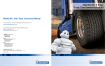
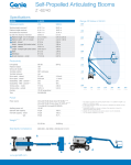
1
Aeris Installation and Service Manual STEMCO Aeris Installation Manual Part Number: 01-571-8300 Revision: 12/4/12 Rev: B AerisTM by STEMCO, an advanced automatic tire inflation system based on patented rotary sealing technology and precision electronic airflow detection. The system is designed to keep commercial trailer tires properly inflated using air pressure from the trailer’s air system. The rotary seal in an automatic tire inflation system is a critical component – it prevents the higher pressures needed to inflate commercial tires (typically 100 psi) from leaking into the wheel end, which can handle no more than 6 psi. Excess pressure can cause the wheel end seal to fail prematurely, causing lubricants to exit the hub thus leaving moving parts susceptible to wear and seizure – a dangerous scenario. The rotary seal employed in AerisTM by STEMCO differs dramatically from currently available systems and is targeted to increase the reliability and durability of these components substantially. In addition to the high reliability and durability of the patented sealing system, AerisTM by STEMCO also includes several one-way pressure relief valves per axle to ensure that the wheel-end is never pressurized. AerisTM by STEMCO also includes a high resolution electronic flow detection technology capable of informing the driver whether the system is making a minor adjustment to tire pressure or if a major leak is present. An additional safety feature is a pressure protection valve to protect the integrity of the air brake system in the case of a major and continuous air leak such as a blow out or other catastrophic tire failure. AerisTM by STEMCO represents a leap forward in automatic tire inflation technology. STEMCO starts with an unwavering commitment to increase the safety of our roadways by protecting the wheel end from damaging air Page 1 of 41 Aeris Installation and Service Manual pressure, and then added several additional safeguards and features. Aeris augments our BatRF tire pressure monitoring systems to complete our suite of tire pressure management solutions. General View of Aeris Components Installed. Refer to this installation guide on how to install the Aeris system on trailers. Page 2 of 41 Aeris Installation and Service Manual Table of Contents General Information……………………………………………………………………………………………………….………. 4 About this Manual……………………………………………………………………………………………………….. 4 Explanation of Signal Words…………………………………………………………………………………………. 4 Important Safety Notices……………………………………………………………………………………….…….. 4 General Service Information…………………………………………………………………………………….….. 5 General Service Installation Note……………………………………………………............................... 5 System Overview…………………………………………………………………………………………………………………….. 6 Aeris Overview…………………………………………………………………………………………………………….. 6 System Features………………………………………………………………………..................................... 6 Aeris Specifications………………………………………………………………………………………………………. 6 System Operation………………………………………………………………………………………………………… 7 How System Works………………………………………………………………………………………….. 7 System Components……………………………………………………………………………………………………..7 Recommended Tool List……………………………………………………………………………………………….. 8 Aeris Installation........................................................................................................................8 Trailer Preparation……………………………………………………………………………………………………….. 8 Axle Preparation…………………………………………………………………………………………………………..9 Drain Oil………………………………………………………………………………………………………….. 9 Remove Welch Plug………………………………………………………………………………………….9 Drill Fixture (How to Make) and Use…………………………………………………………………. 10 Drill & Tap Holes in Axle……………………………………………………………………………………11 Clocking Wheels……………………………………………………………………………………………………………14 Axle Hose Installation……………………………………………………………………………………………………16 Split Loom Tubing Protection Installation………………………………………………………………………17 Center Vent Line Installation…………………………………………………………………………………………17 Axle Plug Installation……………………………………………………………………………………………………. 18 Aeris Hubcap Assembly Installation………………………………………………………………………………. 19 Control Box Installation………………………………………………………………..................................22 Connecting Airlines to Control Box…………………………………………………...............................23 Air Lines to Compressed Air Tank……………………………………………………………………… 26 Tire Hose Installation…………………………………………………………………...................................28 Light Kit and Wiring Installation…………………………………………………………………………………….29 Decal Location………………………………………………………………………………………………………………36 System Installation Check…………………………………………………………………………………………………………37 Maintenance……………………………………………………………………………………………………………………………37 Check Tire Pressure………………………………………………………………………………………………………37 Regulator Setting…………………………………………………………………………………………………………. 38 Troubleshooting Control Box………………………………………………………………………………………………………………………..39 Page 3 of 41 Aeris Installation and Service Manual General Information About This Manual This manual is provided to support the STEMCO Aeris tire inflation system. The manual provides the following information needed to install service and troubleshoot the Aeris system. Explanation of Signal Words Please pay attention to special symbols used through this manual to convey important information. Hazard signal words such as DANGER, WARNING, CAUTION, or NOTICE are used throughout this manual. Information accented by these words indicates a point of emphasis and importance. The following definitions comply with ANSI Z535.4 and indicate the use of signal words as they appear within this manual. ! DANGER: Indicates immediate hazards which will result in severe personal injury or death. ! WARNING: Indicates hazards or unsafe practices which could results in severe personal injury or death. ! CAUTION: Indicates a hazardous situation which, if not avoided, could result in minor or moderate injury. NOTICE: Indicates hazards or unsafe practices which could result in damage to machine or equipment. IMPORTANT: An operating procedure, practice or condition that is essential to emphasize. ! Safety alert symbol used to indicate a condition exists that may result in personal injury or harm to individuals. It must be applied to DANGER, WARNING and CAUTION statements which emphasize severity. IMPORTANT: Please pay special attention to the information supplied in the Explanation of Signal Words section. These words are used to help prevent immediate hazards, unsafe practices, severe personal injury or death and damage to machines or equipment. Important Safety Notices • Proper maintenance, service and repair are important to the operation and reliability of the trailer suspension system and its components. The procedures recommended by STEMCO as described in this manual are methods of performing maintenance, inspection, repair and service. All warnings and cautions should be read carefully to help prevent personal injury and to help assure proper installation methods are used. • Improper maintenance, service and repair can result in personal injury, vehicle damage, property damage, unsafe operating conditions or void the manufacturer’s warranty. Carefully read, understand and follow all safety related information in this manual. ! WARNING: DO NOT modify or rework parts. Use only STEMCO Aeris authorized replacement parts. Use of substitute, modified or replacement parts not authorized by STEMCO may not meet STEMCO’s specifications. This may cause the part to fail which could result in loss of vehicle control and possible personal injury or property damage. Do not modify parts without STEMCO’s authorized written permission. Page 4 of 41 Aeris Installation and Service Manual ! WARNING: Always wear proper PPE when installing and performing maintenance repair, servicing equipment or cleaning tractor or trailer components. ! WARNING: Solvent cleaners can be flammable, poisonous and can burns or serious injury. To help avoid serious personal injury, carefully follow the manufacturer’s product instructions and guidelines. Please follow the procedures below: • • • • • ! Wear proper eye protection Wear proper protective clothing to protect your skin Always work in well ventilated area Do NOT use gasoline, or solvents that contain gasoline. Gasoline can explode and cause serious personal injury or death. Hot tank solutions or alkaline solutions must be used correctly. Follow the manufacturer’s product instructions and guidelines. WARNING: Avoid creating dust from brakes when cleaning around any brake components. Dust from brake pads and/or parts are a possible cancer and lung disease hazard. General Service Information Before starting any work or installation, read, understand and comply with the following: • Read all instructions and procedures. • Company’s service, maintenance, installation and troubleshooting procedures. • Manufacturer’s vehicle safety instructions when working on the vehicle. • Manufacturer’s vehicle instructions not detailed in this service manual. • Follow all local safety regulations and best safety practices when installing. General Service Installation Notes • Work must be performed by trained personnel. • Use all recommended tools required to help avoid personal injury and damage to components. • Be aware of potential power release of tensioned springs on brake chamber or the brake return springs. The release of tension can cause injury. • After installation perform operational checks and test the trailer to make sure the brakes are functioning properly before releasing back into service. System Overview Page 5 of 41 Aeris Installation and Service Manual • The Aeris tire inflation system is designed to automatically inflate tires that are below the target pressure setting. The system uses air from the trailer’s compressed air tank. The compressed air tank pressure setting must be higher than the targeted tire pressure setting. Failure to have the air tank pressure above the target tire pressure prevents proper operation of the inflation system. System Features • Tire pressure is continuously monitored and adjusted automatically to the target tire pressure. • Adjustable air pressure regulator is used for setting desired tire pressure target. • An indicator light will illuminate when air is flowing to the tires. • Does not pressurize axle tube (prevent contamination of seals). • Rotary seal air leakage will not enter the wheel end, preventing oil contamination on the hubcap. • Each wheel end has dual venting paths to prevent wheel end pressurization. • Checks tire pressure constantly. • Integrated check valves in the hoses isolate tires from system if a tire is damaged or leaking. • Tire pressure check ports are integrated into each hose, eliminating the need to remove the hose to check the tire pressure. • An air filter is provided on the inlet air line to prevent particulates from clogging the system. Aeris Specifications • Tire pressure setting range: 70-120 psi • Pressure check interval: Continuously supplies air to tires • System power requirements at 12VDC: < 12W. • Minimum power voltage requirement to operate: 9 VDC • Indicator light current range: 50 mA to 600 mA • Tire inflation capacity (per tire): 10 psi in 2-3 minutes • The indicator light provides the following system information: • No light: System is good • Power up: Light blinks three times • No pressure: Long flash followed by 2 blinks repeating. • Low volume flow: Constantly on • High volume flow: Blinking constantly Page 6 of 41 Aeris Installation and Service Manual System Operation How System Works • The Aeris tire inflation system is designed to continuously supply filtered, regulated compressed air to each tire on the trailer. There is no operation required of the driver for the system to function normally. The only requirement of the driver is to verify the indicator lamp is functioning and to monitor the system periodically. • The Aeris system is preset to maintain a specific tire pressure in each tire. The pressure in the trailer’s air tank must be maintained above the targeted pressure to allow the controller to continuously supply and maintain the preset tire pressure to all tires. IMPORTANT: For Aeris controller to operate properly the air tank pressure must be greater than the tire pressure target. The controller cannot supply tire pressure above the air tank pressure. • When the system is operating properly, the air tank will supply pressurized air to the Aeris controller. The controller will supply regulated compressed air to the air lines going to each tire. If a tire is low, air from the trailer air tank will inflate the tire until the targeted tire pressure is achieved. Regulated air flowing from the controller to the air lines and tires may cause the indicator light to remain on until the target pressure is reached. Constant pressure remains and is maintained in air lines and tires at the targeted pressure. • If a tire is leaking or there is a leak in the lines, the indicator light may illuminate and stay on. If the indicator light stays on for more than 10 minutes, the system is attempting to inflate the tire or trying to correct for the air line loss to the targeted air pressure. If this happens, the operator should stop and check the tires manually to determine if it’s safe to continue to operate the vehicle. Operator should seek service at the next available opportunity. • Remaining tires are protected from pressure loss by check valves integrated into each tire hose. System Components List Hubcaps Spindle plug driver and plugs Air lines and fittings Light indicator and electrical wiring Control box with regulator and filter Control box mounting bracket Flexible wiring conduit Hardware kit Page 7 of 41 Aeris Installation and Service Manual Recommended Tool List 1/2” Drill Drill Speed Recommendations - Drill Speed 7/16” drill…262 rpm to 786 rpm - Drill Speed 5/16” drill…367 rpm to 1100 rpm Drill Bushings (Type SF) 5/16”, 7/16” and 9/16” Drill Bits 5/16”and 7/16” A variable speed ½” drive electric drill is recommended 1/4-18 NPT Tap L1 NPT Plug Gauge Medium to Heavy Duty Extension Cord Wire Strippers Wire Crimper Combination Wrenches – 1/2", 9/16” and 11/16” Hammer Drill Fixture (See page 12) Ratchet and Sockets - 1/2", 9/16” and 11/16” #2 Phillips Screwdriver Bit for Drill Cutting and Tapping Fluid 10” Adjustable Wrench (Crescent) Aeris Installation Trailer Preparation ! WARNING: Before starting any work on trailer, park trailer on a level surface. Chock all wheels in front and back of each wheel to prevent the trailer from moving. Support the trailer with safety jack stands. Do not work under vehicle supported by jack stands only! Jacks can slip and fall over. Serious personal injury or damage to components can result. See Figure 1 ! WARNING: To prevent serious eye injury, always wear approved safety glasses when performing trailer maintenance and service. Page 8 of 41 Aeris Installation and Service Manual Figure 1 Park trailer on level surface. Set trailer parking brake. Chock each trailer wheel. Place jack stands under trailer. Bleed braking system of compressed air. Axle Preparation Drain Oil Place drain pan under hubcap for oil. Remove bolts from all hubcaps and allow oil to drain from each wheel end. Drain Pan Part # 102-5001 Drain oil into pan from each wheel Page 9 of 41 Aeris Installation and Service Manual Welch Plug Removal Remove welch plugs. Drill a small hole off center in welch plug. Hole should be smaller than plug removal spear on the end of slide hammer. Using a slide hammer fitted with a welch plug removal spear to remove the welch plug. Be careful not to score the inside diameter of the spindle bore. If you do not have a slide hammer you may be able to remove the welch plug by using a chisel and hitting the welch plug off center. This should cause the plug to start turning inside the spindle unless there is a shoulder behind the welch plug. Once the plug has turned enough to grab it with a pair of pliers and pull until plug comes out. If plug cannot be removed, drill a 1/2” hole in the welch plug. Make sure as you are drilling the hole you don’t score the inside diameter of the spindle bore. Insert a long steel rod into the 1/2" hole until it hits the back side of the welch plug in the opposite spindle. Steel rod must be longer than the length of the axle. Use a hammer to hit the rod and knock the welch plug out. Pull rod out and repeat procedure on the plug with hole with the 1/2" hole in it. Repeat procedure for second axle. See Figure 2 Drill hole off center for slide hammer or rod. Rod running through axle to other welch plug Figure 2 Inspect the spindle bore for burrs. Remove any burrs using straight die grinder with light grade flapper sanding wheel. Clean the bore of any grinding debris. Check inside spindle to verify that the axle is hollow, which is required for air line passage. Cover bearings and axle nut with clean towel to prevent contamination. Page 10 of 41 Aeris Installation and Service Manual Drill Fixture (Suggested) Drill fixture for aligning holes on axle. Figure 3 1. Drill fixture 2. Drill bushing lock screw 3. Drill bushings - Type SF (3 Sizes) – 5/16”, 7/16” and 9/16”. Figure 4 Determine Axle Requirements: Axle with nothing installed – Start at “Drill and Tap Holes”. Axles with pre-drilled holes but no hardware installed – Start at “Axle Hose Installation” Axle with “Other” tire inflation system – remove airlines and fittings– Start at “Axle Hose Installation” Drill and Tap Holes Clean off axle for drilling holes for air fittings. Review the sketch of how drill fixture is made. See Figure 3 & 4 Drill holes using the drill fixture (Figure 4) to facilitate drilling and tapping of holes for the three air fittings. Use a level to align the fixture and a c-clamp to hold fixture in place (figure 5). Use lubricant for drilling and tapping the holes. Use either an angle drill or standard drill where room permits. With drill fixture is in place (Figure 5) insert the 5/16” drill bushing in fixture and drill a pilot hole using a 5/16” drill bit. Next insert the 7/16” bushing and drill the hole using a 7/16” drill bit. Next insert the 9/16” bushing in fixture and using a 1/4-18 NPT, tap the hole. Repeat procedure on all 3 holes in each trailer axle. IMPORTANT: For some axle configurations, you may be required to remove the slack adjuster and or the air brake chamber in order to access the drill locations specified by the axle manufacturer. Page 11 of 41 Aeris Installation and Service Manual Tap ¼-18 NPT: Proper tap depth determination for a tapered pipe thread (NPT) requires an L1 Plug Gauge, which Stemco highly recommends. If an L1 gauge is not available, an approximation of tap depth can be made by using the actual fitting that will be inserted into the hole. Using only hand applied torque; the fitting should screw into the hole so that 2 to 3 threads are inside the hole before it becomes too tight to turn. This is a trial and error process to get the right depth, so use caution to prevent over-tapping. Once the tap depth is verified, mark that depth on the tap (wrap tape around it, or mark with permanent ink) so the tap can be driven to that depth on future holes. When finished drilling holes, use a cleaning wand connected to high pressure air to blow out shavings from inside of the axle. Use safety glasses. ! WARNING: The use of a drill fixture is recommended. Drilling free hand can create oblong holes. Drilling should be done at a drill speed 7/16” drill…262 rpm to 786 rpm or drill speed 5/16” drill…367 rpm to 1100 rpm. Keep drill straight when boring holes. Tapping should be done by hand only. Do not use a drill for tapping. The use of a drill to tap holes can lead to threads being too deep or breaking the tap. ! WARNING: When drilling the 7/16” hole, be careful as the drill bit breaks through the inside of the axle! The drill bit can hang up causing the drill to twist in your hands. When breaking through the inside of the axle, apply less pressure and drill at a slower speed. 1. 2. 3. 4. Axle Torpedo Level C-Clamp Drilling Fixture Note: Before drilling any holes in axle make sure they will not interfere with any suspension components or brake components. Contact STEMCO for technical assistance at 903-758-9981 in U.S.A. Figure 5 Page 12 of 41 Aeris Installation and Service Manual Axle Manufacturer Hendrickson Hendrickson SAF Holland AXN AXN Meritor Type INTRAAX / VANTRAAX TRIAXLE Location A See Figure 6 See Figure 7 See Figure 8 See Figure 7 See Figure 9 See Figure 7 Trax-Pro 50 Location B See Figure 6 See Figure 7 See Figure 8 See Figure 7 See Figure 9 See Figure 7 Figure 6 Figure 7 Figure 8 Page 13 of 41 Aeris Installation and Service Manual Figure 9 Component Installation Instructions • Wheels on each wheel end (dual tires) must have the valve stems clocked approximately 180° apart for installation of airlines to Aeris hubcap and valve stems on tires. Clocking should be done prior to installing Aeris system. See Figure 10 Clocking Wheels • Clocking dual wheels is important. Proper clocking allows the inner and outer valve stems to align with the hose attachment fittings on the Aeris hubcap. Wheels with 2 hand holes can be clocked so the valve stems are exactly 180° apart, but the valve stems on 5 hand holes cannot be clocked exactly 180° apart. It may be necessary to remove the outer tire and rotate it to clock wheels properly. Page 14 of 41 Aeris Installation and Service Manual Figure 10 IMPORTANT: Cut tubing with a tubing cutter approved for the use on DOT air tubing. Knives, pliers, shears, and other common tools can kink the tubing or not cut it squarely. Poor executed tubing cuts can result in air leaks. Page 15 of 41 Aeris Installation and Service Manual Figure 11 Dual wheels with 2 hand holes, or aluminum wheels with small round valve stem clearance holes require a second alignment procedure to ensure the hoses will not touch the wheel. To ensure perfect alignment between the hose attachment fittings on the hubcap and valve stems, the wheels may need to be rotated one stud clockwise or counterclockwise. See Figure 11. Axle Hose Installation ! WARNING: Before pushing the air line tubing into the axle, disassemble the pass through fitting and place the components over the end of the air line in this order: See Figure 12 • • • Pass Through Cap Rubber O-Ring Pass Through Fitting Body Now place a piece of masking tape over the end of the air line or plug the end of it so no debris can get inside the line as it is being pushed through the axle towards the wheel end. Page 16 of 41 Aeris Installation and Service Manual Figure 12 • Push the cap, o-ring and pass through fitting back approximately 5” in preparation for threading the airline though the axle. • Route the air line through the axle towards the spindle end on each of the outer tapped holes until air line is protruding approximately 8” out of the spindle. If air line hangs up inside the axle, you may need to use something to help fish it through the spindle end. Make sure the air line doesn’t have any kinks in it. Split Loom Tubing Protection Installation • Place one of the supplied split loom tubing protection sleeves over the air line tubing of each spindle end to help protect against sharp edges inside the axle. Repeat steps 1-4 on remaining axle wheel ends. • The air line from the spindle end going to the fitting on the axle fitting can now be cut. Make sure to cut the tubing long enough to reach just past the center of the axle. The air line will be attached to a tee fitting and then tie-wrapped to the center axle vent line. See Figure 13 Center Vent Line Installation • Install the push lock fitting (1/4” NPT x 3/8” tubing) into the center tapped hole and tighten. Insert the supplied 37” X 3/8” nylon tubing with the duck-bill into the fitting. The vent line should be oriented so the duck bill is pointing up and tie-wrap it to frame or hoses of trailer where it’s not going to be part of any moving component. If this option is not possible the vent line can be routed around the axle. Make sure the tubing goes around the axle 1-2 times. Page 17 of 41 Aeris Installation and Service Manual • Tie wrap and secure the end of the air line with the duck bill to the air line coming out of the axle. Make sure the duck bill vent is facing up and there aren’t any big loops of air line hanging below the axle to snag on anything as trailer is moving. Repeat this step on all axles where Aeris is being installed. Figure 13 Axle Plug Installation • Install the axle plug using the axle plug installation tool. The tubing passes through the center of the axle plug which is then inserted into the hole on the installation tool. Align the axle plug with the axle spindle and push leading edge of axle plug into spindle bore. • Now place the face of the installation tool against the axle plug and using a hammer gently hit the handle of the installation tool and seat the axle plug flush with the end of the spindle end. Be careful to drive the axle plug in as straight and even as possible to keep plug from being cocked in bore. Repeat this step on remaining axle wheel ends. Small amount of wheel end lubricant can be applied to the rubber to help aid in installing axle plug. • Using a tubing cutter squares the end of the air line coming out of the axle after removing the masking tape. Leave 5-6” of tubing sticking out of the spindle for easier installation of the Aeris hubcap. See Figure 14 Page 18 of 41 Aeris Installation and Service Manual Figure 14 Aeris Hubcap Assembly Installation • Place the hubcap gasket over the tubing before inserting it into push lock fitting on hubcap. If you are installing a grease application hubcap, make sure to follow recommended manufacturing guidelines for putting grease in bearings before you install the hubcap. IMPORTANT: Make sure grease is applied before installing grease hubcap if hubcap is a grease application. • Install the tubing into the push lock fitting on the Aeris hubcap. Push firmly on to ensure the tubing is fully seated. Now push the hubcap and excess airline back into the axle spindle until the flange of the hubcap is flush with the hub. As the tubing is being pushed back into the axle make sure it doesn’t kink or bend. • Align hubcap gasket with bolt holes on hubcap and install bolts. Install all bolts and snug down until hubcap is seated against the hub. When all bolts are snug use a torque wrench to finish tightening bolts to correct specification. Tighten bolts using a star pattern as shown in figure 16. Torque bolts to 12-16 ft lbs. See Figure 15 and 17 Page 19 of 41 Aeris Installation and Service Manual Figure 15 • Pull gently on the air line coming out of the axle until you feel it get tight. Now push the pass through fitting body down the air line and tighten it into the axle. • Next push the rubber o-ring and the pass-through cap down on the tubing to the fitting. • Before you tighten the pass through cap, push 4-5” of air line back into the axle, making sure not to kink the air line. This will allow enough slack in the air line should you need to remove the Aeris hubcap later. • Tighten the pass through cap on the fitting. Do not over tighten. • Using a tubing cutter, cut air line coming out of the closed pass through fitting on the axle 5” past the center of the axle vent hole. You want to make sure you have enough air line to attach to your tee fittings. See Figure 16 Page 20 of 41 Aeris Installation and Service Manual Figure 16 • Repeat same procedures on remaining ends of all spindles. Make sure when feeding air line tubing into axle it heads towards the correct spindle end. IMPORTANT: Make sure to leave some slack in end of line when cutting for the hubcap airline fitting. If hubcap needs to be removed you will need enough slack to unbolt the hubcap and be able to remove the airline from the air fitting. Figure 17 Page 21 of 41 Aeris Installation and Service Manual Depending on your hubcap type, Remove plug on hubcap and fill with oil to appropriate levels for safe operation. Allow oil levels to stabilize and add oil until at correct levels for each hubcap. IMPORTANT: Make sure oil levels in each hubcap are at the recommended levels for safe operation before using the trailer. Fill and allow oil to settle then check oil levels again. Add as needed to reach the recommended levels. Control Box Installation • Install control box mounting bracket with hardware provided. Mounting bracket can be mounted flush against the back of bracket, flush against top of bracket to a cross member using top mounting holes or welded to the frame. If welding, weld the bracket to the frame before attaching the control box to the bracket. Choose to best option for your application and a location that protects the control box from rocks, debris, etc as much as possible. If trailer has a slider frame make sure bracket is mounted on cross member inside the slider frame box. • Once mounting bracket is in place, install the control box to the bracket using hardware provided. • Mount the control box with the door facing the backend of the trailer if possible. This will help protect it from road debris. If this is not possible mount the control box in a location that allows access to the door, but is as free from as many hazards as possible. Do not mount control box near tires. Control box should be mounted as high under the trailer as possible to keep debris from the road from hitting it and water from getting inside box if trailer is backed into loading dock that may be holding water. See Figure 18, 19 Figure 18 Page 22 of 41 Aeris Installation and Service Manual • The control box has several mounting options. In all mounting options the 5/16” sealing washer, lock nuts and flat washers must be used. The sealing washer is always on the inside of the box. 1. Attach the box (without the bracket) directly to a cross member or frame section using the three 5/16” mounting holes in the bottom of the box. Be sure to leave room at the top for the door to open up. 2. Use the mounting bracket provided with the Aeris system. The bracket can be mounted using the holes on the side of the bracket or the holes in the top flange. The control box can then be bolted to either side of the bracket (holes are symmetrical). 3. The mounting bracket can be welded to the trailer if desired, but the frame must have clearance holes of the 5/16” mounting hardware (nut and flat washer) on the outside of the box. The box must be removed from the bracket before welding and the welded area must have some anti-corrosion treatment such as cold-zinc paint. Figure 19 Connecting air lines to control box • After the hubcap is tightened down, push the rubber grommet on the air line down against the body of the fitting and tighten the nut. Take the tubing from each spindle end and insert it into the air line tee fitting over the center of the axle. It may be necessary to trim off excess tubing going to the center of the axle. Repeat this step on all axles. Page 23 of 41 Aeris Installation and Service Manual • Insert end of tubing into tee fitting on rear axle and run tubing to the front axle tee fitting and insert into front axle tee fitting. Make sure to leave enough airline tubing from rear axle to the front axle for axles that move Independent of each other to distribute load weight. Use tie-wraps to attach tubing to stationary areas to keep tubing from dragging or getting hooked on anything while truck is moving. • On the front axle you will need to insert another tee fitting into the airline to connect the air supply to outlet side on the control box. All airlines connected to the hubcap from each axle will be hooked up to the outlet side of the control box mounted under the trailer. See Figure 20, 21 and 22 • Recommended to route and tie wrap airlines coming off the axles to existing wiring or tubing going towards the location where the control box is mounted making sure airlines won’t be rubbing against any sharp edges that may damage airlines. • Center vent lines should be tied up under trailer so that duck bill vent is vertical and so that duck bill won’t risk being under water if trailer is parked in a loading bay that may hold water. Make sure to tie wrap center vent line to the trailer in an area that isn’t a moving component which could risk it being pulled on. Vent line may be wrapped around axle if needed, just make sure duck bill is facing vertically and then tie wrap vent line to fitting coming of the axle to hold it in place. Figure 20 Page 24 of 41 Aeris Installation and Service Manual Figure 21 Page 25 of 41 Aeris Installation and Service Manual Figure 22 Air Lines to Compressed Air Tank IMPORTANT: Open petcock valve on compressed air tank to release air pressure from tank. Once compressed air is drained from the tank, close the petcock valve. • Remove large 3/8” Plug from side of compressed air tank. • Install the 3/8” NPT-M x 1/4” NPT-F bushing. • Install the 1/4” nipple. • Install “Inlet” side of the Pressure Protection Valve on nipple. • Install the 90° swivel elbow 1/4" NPT-M X 1/4” tube/DOT fitting to “outlet” side of PPV. • Run a piece of 1/4” tubing from the 90° swivel elbow to the “Inlet” side of the control box fitting. • Make sure the mini ball valve on the “inlet” side of the control box is in the open position. See Figure 23 Page 26 of 41 Aeris Installation and Service Manual Figure 23 1. 2. 3. 4. 5. 6. Item Description Air tank Outlet Air Supply of Control Box Inlet Air Supply of Control Box Pressure Protection Valve Air Supply From Tractor Aeris Hubcap Axle Air lines Trailer Air Tank Attach air lines from Aeris hubcap to “Outlet” side of control box Attach air lines from PPV to “Inlet” side of control box Required; 70 psi minimum closing pressure Air supply hooked to air tank coming from the tractor compressor Air line from Aeris hubcap axle air lines hooked to “Outlet” on control box 1/4" tube tee air line fittings to hook air lines from axles to air tank Air lines and electrical wiring run to control box for Aeris system Air shut on/off valve. Must be in ”Open” position for Aeris system to work 7. 1/4" Airline “Tee” Fittings 8. Control Box 9. Mini Ball Valve Page 27 of 41 Aeris Installation and Service Manual Tire Hose Installation • Attach air hoses to the hubcap and the inner and outer valve stems. The hose with the 180° fitting attaches to the outer valve stem. Turn the valve stem swivel nut on the fitting until the rubber gasket just makes contact with the valve stem, then turn the nut 1/2 turn more to ensure proper sealing. Now push the hubcap end of the hose into the brass hose adapter fitting and turn the nut until the fitting is snug. For final tightening, turn the check port stem and the nut at the same time using only your fingers. Do not use any type of valve stem extensions. See Figure 24 and 26 • If installing on Super-Single wheel only one hose is required. See Figure 25 Dual tire hose to hubcap connection Wide base single tire hose to hubcap connection Figure 24 Figure 25 IMPORTANT: Make sure the hose(s) are not touching the tire rim. Contact between the hose and the rim could damage the rim. IMPORTANT: Make sure the tire hose(s) are not stretched so tightly that it puts a strain on the valve stem or the hubcap fittings. Clock wheels if hoses are not aligned with the valve stems. Page 28 of 41 Aeris Installation and Service Manual Figure 26 Light Kit and Wiring Installation • Once the control box is mounted and the air lines are connected to the controller, the electrical wiring and light kit can be installed. Improper wiring or operation of Aeris system can lead to the driver not being aware the tire inflation system is malfuncting. • This section gives the basic instructions on wiring the Aeris system and routing the electrical wiring from the power source to the control box and light. Hardware kit is shown below with items needed to install wiring and light. See Figure 27 Page 29 of 41 Aeris Installation and Service Manual 2 3 10 1 8 7 4 5 9 6 Figure 27 Item Qty 1. 2. 3. 4. 5. 6. 7. 8. 9. 10. 1 7 5 3 3 1 111 25 - Description Wire Extension for light 10 X 1 1/4” Self Tap screw P-Clamps Wire Ring Terminal Wire Female Disconnect Wire Butt Splice Light Pigtail Light Spacer 6” Tie-wraps Used to connect light to light and 7 pin power box. Used to attach light and P-clamps to trailer Used to clamp down wire from light to trailer and to 7 pin power box Connectors for end of wires to 7 pin power box. Used to connect white, yellow, and brown wire to Aeris controller box. Used to connect light black wire to yellow wire from controller box Used to connect light to wire extension to 7 pin power box. Aeris signal indicator Used for mounting lamp11 Used to secure wiring and airlines to trailer components. • Run the 3 wire cable down through the front of the trailer in conduit or space provided by the trailer manufacturer. Make sure the cable stays inside the conduit or track between the tractor and the trailer. Failure to do so may cause the wire to be damaged. See Figure 30 • Make sure to route the 3 wire cable under the trailer through the same holes that the brake airlines and other electrical lines are running through. Make sure to secure the cable every 15 -20 inches using the tiewraps provided. Any excess cable that is not being used needs to be cut or bundled and tie-wrapped to existing cable routings under the trailer. See Figure 28 Page 30 of 41 Aeris Installation and Service Manual IMPORTANT: Make sure to run the 3 wire cable along the same path the airline from the brakes is routed. This will insure that you have enough slack in the electrical line to keep it from be damaged by any moving parts on trailer. See Figure 29 Figure 28 Figure 29 IMPORTANT: Do not allow 3 wire cable to rub against a sharp edge of a hole or straight edge of a structural cross member as cable is being routed through the trailer. Use tie-wraps to secure to existing airlines or electrical lines. Page 31 of 41 Aeris Installation and Service Manual Figure 30 Page 32 of 41 Aeris Installation and Service Manual Figure 31 • Once wire cable is pulled to the mounted controller box at the back of the trailer cut the cable. Make sure to leave enough wire to have about 12” of wire inside the control box. • Pull wire cable into the bottom of the control box through the cable gland. Once wire is inside the box, tighten the nut to seal up around the cable. Tightening the cable gland will prevent water from entering the box and helps keep the cable from being pulled on which could lead to damaging the board inside the control box. • Next strip the wire jacket from around the 3 wires back about 4” using a jacket stripping tool. Make sure not to cut insulation around 3 wires inside jacket. • Next strip 1/4” of insulation from the white, brown and yellow wires. • Crimp the female wire disconnect (spade) terminals to the white, brown and yellow wires using a crimping tool. • Now connect the yellow wire to the “Light” terminal on the board, the brown wire to the “Power” terminal on the board and the white wire to the “Ground” terminal on the board. Page 33 of 41 Aeris Installation and Service Manual • Make sure to leave a loop at the bottom of the wires on the bottom of the control box. This keeps water from running down the cable to the electrical board inside the control box. See Figure 31 • Close box cover and snap lid clamps. Depress the Schrader valve pin to discharge the pressure DRIP LOOP Figure 32 • Take the light and using the pigtail provided plug the square flat ends of the pigtail into the 2 holes on the back of the light. Make sure connectors snap in place fully. • Now on the other end of the pigtail, remove the 2 plugs in the ends of the connectors and plug in the wire extension. Make sure connectors snap in place fully. • Mount light in front corner of or side of trailer. Mount light in location where driver can see it in driver’s side view mirror. • Mount indicator light to trailer using the self tapping screw provided. Make sure to tuck wires inside back of light and where wires come out of slots provided to keep from pinching wire when mounted. • Secure wire to trailer using p-clamps. Make sure wiring is not hanging down to catch on anything. IMPORTANT: Make sure that as you are installing the p-clamps you run the wire with a drip loop in the bottom of cable below the 7 pin connector box. This keeps water from running down the cable from the indicator light into the electrical box. See Figure 34 • Remove the cover to the trailer 7 pin connector box. See Figure 33 Page 34 of 41 Aeris Installation and Service Manual • Route the wire from the light into the 7 pin connector box. Route enough wire into the box to have about 8” of wire sticking out and cut off excess wire. Strip about 5” of the wire jacket from the wire using a jacket stripping tool. Make sure not to cut jacket so deep you cut into the insulation on the wires. • Strip off 1/4" of insulation from the black and white wire. • Route end of the 3 conductor wire into the 7 pin connector box. Strip the wire jacket from around the wires back about 6” using a jacket stripping tool. Make sure not to cut jacket so deep you cut into the insulation on the wires. • Next strip 1/4” of insulation from the white, brown and yellow wires. • Crimp a ring terminal on the end of the white wire from the light and crimp a ring terminal on the white wire going to the control box. Both white wires coming to the 7 pin connector box should have a ring terminal crimped to them. Use a terminal crimping tool. • Crimp ring terminal to the brown wire. • Crimp butt splice to the black wire from the light and the yellow wire from the 3 wire cable going to the control box. • Remove the nut from (Pin 1 biggest pin) on the 7 pin connector terminal and place both the white wires from the 3 wire cable andthe light on the post. Replace nut and tighten down. • Remove the nut from (Pin 7) on the 7 pin connector and connect the brown wire from the 3 wire cable to the post. This will be the center pin and will carry the power on systems that support ABS. Page 35 of 41 Aeris Installation and Service Manual Figure 33 • Next tuck all the wires inside the 7 pin terminal box and install the cover back on the box. Make sure you don’t trap any wires between the cover and the box that could cause the wire to short. • Use tie wraps to attach 3 wire cable and wire cable from the light indicator to the airlines leading out of the 7 pin connector box. See Figure 34 IMPORTANT: Make sure you leave enough slack in the wires in the connector box to be able to remove the cover and work on the wiring without pulling any of the wiring lose from connectors when removing the cover of the box. Page 36 of 41 Aeris Installation and Service Manual Figure 34 Decal Location • Place decals on front of trailer by the indicator light and on the inside and outside of the control box cover. See Figure 34 Figure 35 Page 37 of 41 Aeris Installation and Service Manual System Installation Check • After the Aeris system is completely installed, but before the trailer is put back into service, all air system connections need to be checked for leaks. Apply a soapy/water solution to all air connections. If bubbles appear at any fitting or air connection, repair the connection. Follow Instructions Below: Make sure the petcock valve on the trailer air tank is closed. Fill the trailer air system and set all tire pressures just below the target pressures. Ensure the mini ball valve on the controller box is in the open position. Verify the trailer is connected to 12-volt power source. Verify the “Red” light on the circuit board in the control box is blinking. If after applying 12-volts you don’t see the light blinking, disconnect the 12-volt power source and check all wire terminal connections and connections to the 7 pin connector box correct. Indicator light on trailer should come on and blink 3 times. If insufficient pressure exists in the system, the light will blink in a pattern of 1-long and then 2 short blinks, if low flow exists the light will stay on constantly and if high flow exists the light will blink constantly. If the indicator light remains on and the system continues attempting to inflate one or more tires to the proper pressure but can’t due to the inability to maintain adequate pressure, the system has a leak and must be repaired. Verify the oil level in each wheel end is at the correct level. Maintenance Check Tire Pressure • Although the Aeris tire inflation system is designed to detect and fill a tire that’s leaking during vehicle operation, STEMCO recommends you inspect the tires for normal wear and damage at regular intervals and check the tire pressure as follows. • Remove the metal cap from the check port that is provided on each hose. See Figure 36 Page 38 of 41 Aeris Installation and Service Manual Figure 36 • Check pressure going to each tire using a pressure gauge. • If the tire pressure is lower than expected: Replace fill cap and hand tighten. • If the tire pressure is lower than expected: • Verify that the shut off valve is in open position. • Check all air connections with soapy water solution. If bubbles can be seen, tighten fittings and check again with soapy water solution. • If pressure is too high release some pressure from the tire dropping the tire pressure below the desired target pressure. • The Aeris system will automatically inflate the tire to correct setting. • Each tire should be checked for correct air pressure a minimum of once every 3 months. Regulator Setting It’s recommended that you check the regulator pressure once every 3 months to verify the regulator is still set at the desired pressure setting. To set the regulator pressure, follow the steps below. • Open the cover to the control box. • Remove the metal cap on the check port fitting on the regulator. • Check the pressure with an accurate gauge, such as a master gauge. Page 39 of 41 Aeris Installation and Service Manual • If the pressure is correct, replace metal cap and close the lid. • If the pressure is above or below the desired setting, adjust the pressure using the adjustment knob. See Figure 36. • If the pressure is “low” pull up on the regulator’s knob to unlock. Turn the knob clockwise to increase the pressure. Allow the pressure to stabilize then check the pressure 2-3 times to verify correct pressure. If the pressure is correct, push the knob back down to lock in place and replace the metal cap. • If the pressure is “high” turn the knob counter-clockwise to decrease the pressure. Allow the system to stabilize and check the pressure 2-3 times to verify correct pressure. Continue to decrease or increase the regulator until the desired pressure is achieved. Figure 37 Troubleshooting AERIS Control Box installation debugging techniques With the entire system connected apply power. Does the red light on the circuit board blink at power up? If no then check power connections +12 and Ground continuity to the circuit board and 7 pin connector. After power up works successfully take off the power lead and the light lead and connect them together the light should light up. Page 40 of 41 Aeris Installation and Service Manual If no then the connection to the light yellow line is not connected or the light is not grounded. If both light and board power up then connect all wires back to the circuit board and verify that system powers up and blinks three times on a power up event both on the circuit board and at the front light on the trailer. If the lights on the circuit board blink but the light on the trailer does not then you have a circuit board problem. If both the light on the trailer and the light on the board blink 3 times next check that the blinking stops or that the light on the front of the trailer goes to a solid on state or consistent blink state or an off state. Those are all three valid states. If the light on the trailer keeps blinking but in an inconsistent manner like two fast then one slow this means that pressure has not reached the control box yet. Check that the air control valve is in the on position. If the control valve is in the on position then the brake system has not received enough air to open the PPV valve yet. Wait for the airbrake tank to fill or check glad hands are connected to the tractor. If the light stays on solid or blinks consistently in timing then the system is taking air. If no hissing is heard coming out of the air connections then the tires are low and simply taking air. If hissing is coming from an air connection, fix the leak. If the light goes out after the first 3 blinks then all is ok and tires are aired up. WARRANTY INFORMATION: All warranty returns may be sent to: TS 16949 STEMCO, BAT RF, and AirBAT are all registered trademarks of STEMCO LP © 2012 P/N 015718300 STEMCO 300 Industrial Blvd. Longview, TX 75691 Attn: Warranty Dept. Stemco - USA Stemco - Canada P.O. Box 1989 Longview, TX 75606-1989 (903) 758-9981 • 1800-527-8492 FAX: 1-800-874-4297 5650 Timberlea Blvd. Unit B Mississauga, ON L4W 4M6 (905) 206-9922 • 877-232-9111 FAX: 877-244-4555 www.stemco.com Page 41 of 41