1
-
--
-- -- -- - -
-
-- - - - - -- -
(/"-
)
1975
Scorpion
Brut
J
Service Manual
Engine Section
)
1-l
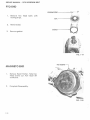
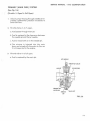
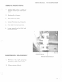
SERVICE MANUAL· 1975 SCORPION BRUT
ENGINE SYSTEM
General Description:
The Scorpion Brut e ngine is especially designed
and
built
for
today's
high
performance
snowmobile.
Any internal combusion engine performs best
and is most reliable at a constant operating temperature. The Scorpion Brut engine is thermostatically controlled to run at a 180 degree+4
degree F cylinder head temperature whether the
outside temperature is -30 degree F or +50
degree F. This close temperature control reduces
to a minimal, the necessity of changing spark
plugs and the worry of piston seizing.
However, in order to get the best possible use
and ensure that it retains its high degree of
dependability, performance and endurance, it
must receive proper care and maintenance.
Therefore, it is necessary to know something
about the basic fundamentals of this engine and
how it functions.
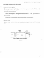
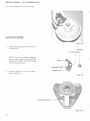
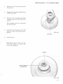
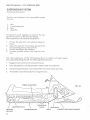
OPERATION
The Scorpion Brut engine uses a mixture of
gasoline, oil and air for combustion, lubrication
and cooling. It fires on every stroke of each
piston. There are two or three power strokes
(depending on the model), for every revolution of
the crankshaft.
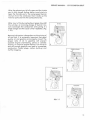
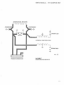
As the piston moves upward in the cylinder, it
draws the fuel/air mixture into the crankcase
through the intake manifold while at the same
time compressing fuel that has been forced into
the combustion chamber (Fig. 1- 1A).
As the piston nears top dead center, the spark
plug is fired and the compressed fuel/air mixture
burns and expands, thereby forcing the piston
downward on a power stroke.
As the downward stroke of the piston turns the
crankshaft, it a l so starts to compress the fuel/air
mixture in the crankcase and, simultaneously,
opens the exhaust por t and closes the intake port
(Fig. 1-1 B & C).
1-2
)
SERVICE MANUAL · 1975 SCORPION BRUT
After the exhaust port is fully open and the intake
port is fully closed, further piston travel starts to
open the transfer ports. The compressed fuel/air
mixture from the crankcase th en travels up the
transfer ports and into the combustion area.
After most of the burned exhaust gases have left
the cylinder, an incoming charge of fuel/air mixture scavenges the combustion area giving it a
fresh charge and the cycle is then repeated. (Fig.
INTAKE
1-lD).
Because lubrication is dependent on the mixing of
oil and fuel, it is extreme ly important that good
quality oil and gasoline are properly mixed. The
proper ratio of oil to gasoline will prevent
possible engine overheating, piston or cylinder
scoring, or eventua l engine seizure. Too much oil
and not enough gasoline can lead to incomplete
combustion, fouled pl'-'gs, carbon build-up and
muffler clogging.
EXH/UST
TRANSFER
FIG. 1-1
1·3
SERVICE MANUAL · 1975 SCORPION BRUT
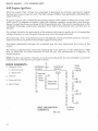
TABLE OF SPECIFICATIONS
IDENTIFICATION
SIZE
TORQUE
Cylinder Head Nuts
8mm
20Ft. lbs.
Cylinder Base Nuts
10 mm
25Ft. lbs.
Flywheel Nut
45-50 Ft. lbs.
Intake Manifold Nuts
8mm
20Ft. lbs.
Exhaust Manifold Nuts
8mm
20Ft. lbs.
Water Manifold Nuts
6mm
15Ft. lbs.
Crankcase Bolts
8mm
20Ft. lbs.
10 mm
25Ft. lbs.
CRANKCASE BOLTS TORQUE SEQUENCE
•
20
• • • • • • • •
15
11
7
3
1
6
10
14
10 mm Bolts Circled
All others are
e18
16
17
19
•
13
9
5
2
4
8
12
• • • • •• • • •
•
440 Brut is shown. Use the same torquing pattern for the 340 Brut which has
12 instead of 18 - 8 mm bolts.
CYLINDER HEAD NUT TORQUING SEQUENCE:
340, 440 Models
®
1-4
(1)
SERVICE MANUAL· 1975 SCORPION BRUT
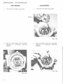
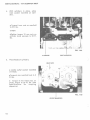
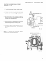
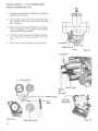
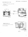
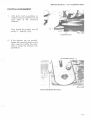
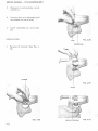
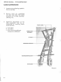
ENGINE REMOVAL
(
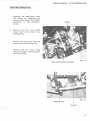
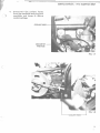
1.
2.
Separate the carburetors from
the engine by removing the
clamps which secure the rubber
connectors to the carburetor
outlet.
CLAMPS
Remove the 3/8" nuts which
fasten the tie rod ends to the
steering frog.
Remove the cotter key from the
lower end of the steering frog.
Remove the 2lf4" bolts which
secure the upper steering bracket to the roll bar.
FIG. 1·2
CARB. ELBOW MOUNTING SCREWS
FIG. 1·3
STEERING FROG
TIE RODS
l -5
SERVICE MANUAL· 1975 SCORPION BRUT
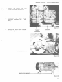
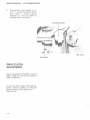
Lift the steering post clear of the
engine area.
UPPER STEERING BRACKET
/
f
FIG. 1·4
3.
Disconnect the engine electrical
connectors, spark plug leads and
the temperature light wire from
th heat sensing element.
FIG. 1-5
SENSING ELEMENT----+-----=
CONNECTOR
FIG. 1-6
1·6
SERVICE MANUAL· 1975 SCORPION BRUT
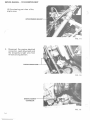
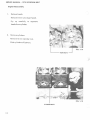
4.
Disconnect the coolant hoses
from the manifolds and plug both
manifolds and hoses to reduce
coolant spillage.
COOLANT BY·
PASS HOSE
FIG. 1-7
(
FIG. 1·8
HOSE---I
1-7
SERVICE MANUAL· 1975 SCORPION BRUT
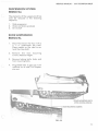
5.
Remove 2-7 /16" lock nuts which
secure the front motor mounts to
the chassis.
Remove the 6 - 8 mm screws
which secure the rear motor
mounts to the engine.
6.
Release the springs which fasten
the exhaust wye to the muffler.
7.
lift the engine from the sled and
drain the coolant.
. ,,
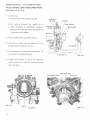
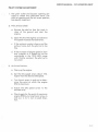
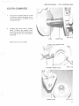
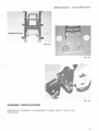
ENGINE DISASSEMBLY I
ASSEMBLY
Disassembly (Peripheral Equipment)
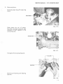
1.
Remove the carburetor to engine
Elbow connectors. (2 socket head
screws/elbow) See Fig . 1-2.
2.
Disconnect the exhaust
(Socket head screws).
3.
Disconnect the coolant by-pass
hose. (2 clamps). See Fig. 1-7.
wye
FIG. 1-10
l -8
SERVICE MANUAL· 1975 SCORPION BRUT
4.
Remove the coolant inlet and
outlet manifolds. (6 mm nuts).
5.
Disconnect the water pump
mounting brackets. (3 - 8 mm
bolts).
6.
Remove the front motor mounts
from the engine.
COO~ANT
OUTLET
MANIFOLD
COOLANT
INLET MANIFOLD
FIG. 1-12
FIG. 1-13
1-9
SERVICE MANUAL· 1975 SCORPION BRUT
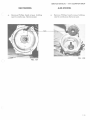
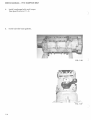
Engine Disassembly
1.
Remove heads.
Remove 8 mm nuts (6 per head).
Pry
up
carefully
to
separate
heads from cylinder.
2.
Remove cylinders.
Remove 10 mm cylinder nuts.
Slide cylinders off pistons.
FIG. 1-14
~---
HEAD NUTS
FIG. 1-15
CYLINDER NUTS
].] 0
SERVICE MANUAL- 1975 SCORPION BRUT
3.
(
Remove pistons.
Extricate snap ring with snap ring
pliers.
SNAP RIN
FIG. 1-16
Slide piston pin out of piston.
Exercise care that excessive side
pressure is NOT applied to the
connecting rod.
(
FIG. 1-17
Pull piston from connecting rod.
Remove pin bearing and bearing
spacers.
FIG. 1-18
1-1 1
SERVICE MANUAL - 1975 SCORPION BRUT
PTO END
LOCKING STRIP
1.
Remove hex
locking strips.
2.
Remove seal.
3.
Remove ga sk e t.
head
bolts
---------1~
)
~'
with
FIG. 1-19
)
MAGNETO END
1.
Remove Recoil Starte r . Tak e h ex
head screws out. Pull recoil off
crankcase.
2.
Complete Disassembly.
HEX SCREWS
t
FIG. 1-20
1-12
SERVICE MANUAL • 1975 SCORPION BRUT
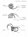
340MODEL
a.
440MODEL
Remove pump pulley bolts, emergency rope pulley and water pump pulley.
a.
Remove 6 mm pump pulley bolts,
emergency rope pulley and water
pump pulley.
.,. .>'' "---------,.,.- --k
+·~ . ~
EMERGENCY ROPE PULLEY----,
?'.
'*
WATER PUMP PU
FIG. 1-21
b.
Remove 18 mm nut holding rotor on
shaft.
b.
Remove 18 mm nut holding rotor on
shaft.
FIG. 1-23
FIG. 1-22
l-1 3
SERVICE MANUAL- 1975 SCORPION BRUT
l
440MODEL
340MODEL
c.
c.
Pull rotor from shaft using puller.
Pull rotor from shaft using puller.
ROTOR
FIG. 1-24
j
d.
Take out pulleys head screws holding
magneto to crankcase. Remove
magneto.
d.
..
Take out Phillips head screws holding
magneto to crankcase. Remove
magneto .
FIG. 1-26
FIG. 1-25
)
1-14
SERVICE MANUAL· 1975 SCORPION BRUT
340MODEL
e.
Remove Phillips head screws holding
seal to crankcase- Remove seal.
440MODEL
e.
Remove Phillips head screws holding
seal to crankcase. Remove seal.
FIG. 1-28
)
FIG. 1-27
I
(
1-15
SERVICE MANUAL- 1975 SCORPION BRUT
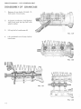
DISASSEMBLY OF CRANKCASE
1.
Remove 8 mm bolts (18-440, 12340) and 2-1 0 mm bolts.
2.
To loosen crankcase, hold bottom
half firmly and tap top half with
plastic mallet.
3.
Lift top half of crankcase off.
FIG. 1-29
4.
Lift crankshaft out of lower half of
crankcase.
FIG. 1-30
FIG. 1-31
FIG. 1·32
1-16
SERVICE MANUAL- 1975 SCORPION BRUT
ENGINE ASSEMBLY
(
Assemble Crankcase/Crankshaft.
1.
lay lower half of crankcase on
work bench. Grease.
2.
Place crankshaft in crankcase
with positioning ring in groove.
• Install rotor key in crankshaft
carefully. (440 Model only).
• Grease labyrinth seal and oil
bearings.
FIG. 1-33
3.
(
Apply gasket sealer on lower half
of crankcase.
• Place upper half of crankcase
on lower half.
FIG. 1-34
LABYRINTH
SEAL
(
FIG. 1-35
1-17
SERVICE MANUAL· 1975 SCORPION BRUT
4.
Install crankcase bolts and torque
(See Specifications: P. 1-4).
)
5.
Install cylinder bose gaskets.
FIG. 1-36
)
FIG. 1-37
I
l-18
SERVICE MANUAL • 1975 SCORPION BRUT
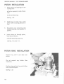
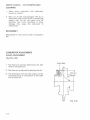
SEAL PLATE INSTALLATION
SEAL
MOUNTING
SURFACE
\
1
1.
Measure distance from seal mounting
plate surface on case to outer race of end
bearing on shaft. (Use depth micrometer).
2.
Select and install correct end gasket
depending upon depth measurement as
follows:
Depth Measurement
.091 and over
.08 1 to .091
.080 and less
Gasket Thickness
.2 mm (.003")
.3 mm (.0 12")
.5 mm (.020")
3.
Bolt seal plate in position.
4.
Bend lock tabs to secure plate bolts.
FIG. 1-38
)
FIG. 1-39
}
/
FIG. 1-40
FIG. 1-41
1-19
SERVICE MANUAL- 1975 SCORPION BRUT
PISTON INSTALLATION
1.
Place piston pin bearings in connecting rods.
• Position spacers at ends of bearings.
• Lubricate bearings.
See Fig. 1-1 8.
2.
Install one {1) snap ring in each
piston before placing pistons on
rods.
3.
Slip pistons over connecting rods
holding bear.ings and spacers in
position.
4.
Insert piston pin through piston,
bearing and spacers.
elnstall remaining snap ring.
See Fig. 1-16, and 1- 17.
PISTON RING INSTALLATION
Expand ring until it just slips over
piston.
Do not expand
necessary.
any
further
than
Position rings so that ring notch slides
over ring locating pin .
See Fig. 1-42.
FIG. 1-42
1-20
SERVICE MANUAL • 1975 SCORPION BRUT
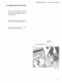
CYLINDER INSTALLATION
1.
Position cylinder so that the intake port (carburetor side) is
toward side of crankcase with impulse fittings.
2.
Place wooden block or other support crankcase to support piston.
3.
With ring compressor over rings,
slide cylinder onto piston.
PISTON
SUPPORT
(
RING COMPRESSOR
-----r
FIG. 1·43
l -21
SERVICE MANUAL- 1975 SCORPION BRUT
4.
With cylinders in place, place
inlet coolant manifold on cylinders,
I
• Torque 6 mm nuts on manifold
to 5 Ft. lbs.
eTHEN
•Tighten torque 10 mm nuts on
cylinder studs securely to 25 Ft.
lbs.
\
,,,,,It,.
.r
FIG. 1-44
INLET MANIFOLD
CYLINDERS
5.
Place heads on cylinders.
)
HEAD NUTS
~
• Locate outlet coolant manifold
on heads.
J
v
eTorque 6 mm manifold nuts to 5
Ft. lbs.
Torque 8 mm head nuts on
•
studs; torque to 20 Ft. lbs. (See
Specifications
for
torquing
sequence).
FIG. 1-45
OUTLET MANIFOLD
1-22
SERVICE MANUAL • 1975 SCORPION BRUT
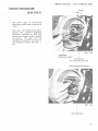
TIMING PROCEDURE
POINTS
CAM
(340 O NLY)
1.
Set point gap at maximum
opening on both sets of points at
.015 ".
Fig . 1-46, 1-47 illustrations show
specia l cam (without magnetic
f lywhee l) installed so tha t gap
check can be seen. Under no rma l
cond i tions , t he gap w il l be
checked th r ough the windows in
the f lywhee l (rotor) . See Fig . 1-
49 ).
ARMATURE
MOUNTING SCREW
CAM
LLER
(AT HIGH POINT ON CAM}
(
POINTS MOUNTING SCREW
FIG. 1-47
.015 POINT GAP
(
l-23
SERVICE MANUAL - 1975 SCORPION BRUT
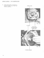
2.
Install special bolt in flywheel to
hold the weight arms in the "full
advance" position.
WEIGH
ARMS
FIG. 1-48
FLYWHEEL
SPECIAL BOLT
FOR POSITIONING
WEIGHT ARM
FIG. 1-49
FLYWHEEL WINDOW
)
1-24
SERVICE MANUAL· 1975 SCORPION BRUT
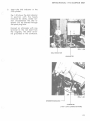
3.
(
Insert the dial indicator in the
PTO cylinder.
Fig. 1-50 shows the dial indicator
in position with the heads
removed for clarity. Under normal circumstances the dial indicator will be inserted through
the spark ptug hole.
Connect an ohmmeter with one
terminal to the red lead from
the magneto, the other terminal grounded to the crankcase.
DIAL INDICATOR
OHMMETER
(
)
I
!;
OHMMETER GROUND
0
("HOT" LEAD CONNECTED HERE)
1-25
SERVICE MANUAL - 1975 SCORPION BRUT
4.
Locate top dead center of the
pist on travel.
Set the dial indicator on zero.
See Fig. 1-50.
5.
Rotate the crankshaft counterclockwise until' the indicator
read s
.250".
Set the ohmmeter scale selector
at RX1.
Adju st the needle reading to 4 on
the resistance scale.
See Fig. 1-50.
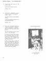
6.
Rotate the crankshaft clockwise
until the ohmmeter indicates a
sudden decrease in resistance.
This means that the points have
closed.
RESISTANCE READING DROP
The dial indicator should read
.150" to . 160". See Note.
If the dial indicator reads outside
this tolerance, adjust to within
tolerance by loosening the moun ting screws and rotating the
magneto (armature plate) in the
applicable direction.
NOTE: Timing is set at .150-.160
full advance (340 Brut) when new
points are use d to allow for
break-in of point rubbing blocks.
After approximately 3 hours of
operation, the timing should be at
.138 full advance (normal).
FIG. 1-52
DIAL INDICATOR RDG.
(.1 50 - . 160)
1-26
SERVICE MANUAL- 1975 SCORPION BRUT
7.
8.
Shift the dial indicator to the #2
cylinder (magneto end). Connect
the ohmmeter terminal to the
white lead from the magneto.
Adjust the point closing position
to within .005" of the position
established for the #1 cylinder.
This is done by loosening the
points mounting screw and adjusting the point gap in the
necessary direction. (See Fig. 1-
47).
( I
FIG. 1-53-
1-27
(
)
1975
SCORPION
BRUT
(
)
Service Manual
Carburetor
Section
('
2- l
SERVICE MANUAL - 1975 SCORPION BRUT
FUNCTIONAL DESCRIPTION:
GENERAL
)
Th e purposes o f the carburetor are:
( 1) to break fu e l into tiny partic les (vaporize)
(2) to mix the fuel with air in the proper ratio and
(3) to deliver the combustible mixture to the engine.
Pulsations from the crankcase through the impul se tube actuat e th e fuel pump diaphragm to
transport fuel from the tank into the carburetor. As engine fuel demand increases , differential
pressure f orces fuel from the carburetor float bowl through app li cab le orifices, jet s a nd passages
into the main bore and from the bore into the engine. The floats actuate the carb u retor needle
valve to maintain an adequate fuel supply in the bowl for all eng ine demands.
In order for the carburetor to provide the correct air/fuel ratio under all eng ine loads, four
sepa rate fluid circui t s are provided:
(1) Starter Syst em
(2) Pilot System
(3) Main System
(4) Float System
The schematics included in the section are functionally correct but do not necessar ily represent
the actua l physical appearance of the carburetor. A signif icant departure from t h e physical
arrangement occurs in connection with the main jet.
The schematic indicates the main jet to be attached to the lower end of the need le je t. On the
Mikuni carburetor used on the Brut, the main jet is located in the main je t holder (See FIG . 2 - 12).
but it st ill performs the same function.
On this carburetor, the fitting on the l ower end of the needle jet serves to hold t he needle jet in
position. It is bored out larger than the main jet so that it does not restrict the fluid f lo w.
2-2
SERVICE MANUAL • 1975 SCORPION BRUT
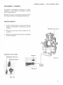
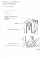
STARTER (FUEL ENRICHING) SYSTEM
(See FIG. 2·1, 2-2)
( j
1. The fuel is metered through the starter jet.
2. The fuel is broken into particles and mixed
with air as it travels through the emulsion
tube.
r -·- -l
3. The mixture flows into the area vacated by
the Fuel Enriching Valve and there is mixed
with air from the intake port.
: I - - ~Jt=!:=====~
~*'(;:r,t--:; -
J
I
-~-'
4. The final mixture is delivered to the engine
intake through the fuel discharge port.
INTAKE PORT
5. The starter sy stem is activated by the Fuel
Enriching Valve Control on the instrument
panel.
EMULSION TUBE
STARTER JET
FIG. 2-1
)
NOTE: It i s important that the throttle valve is
closed during the Starting Operation.
ENRICHING VAlVE COVER
FIG. 2-2
2-3
SERVICE MANUAL • 1975 SCORPION BRUT
I
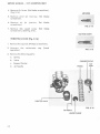
PILOT SYSTEM (LOW SPEED OPERATION)
(See FIGS. 2-3, 2-4, 2-5)
1. Conditions:
a. The throttle valve is nearly closed.
NEEDLE JET
AIR FLOW
BY-PASS
b. Air velocity through the needle jet is
slow, resulting in insufficient negative
pressure to draw fuel from the needle jet
in the main fuel system.
2. Fuel is metered through the pilot jet.
3. The fuel is mixed with air adjusted to the
I I
proper amount by the air screw.
4. The mixture is mixed with additional air
coming in through the by-pass.
~
AIR SCREW
1
11
II
I I
L- - -_
-....,..
....... -_ - _ - _- _- ____
- - _, I
l
I
II
I I
~ -_ ~--:...-_-_-=--=---::::_-_ - ~-~-- -_-_-=--_-'~
PILOT JET
FIG. 2-3
5. Finally the mixture is drawn through the
pilot outlet to mix with air flowing through
the main bore.
EMULSION TUBE
IDLE SPEED SCREW
FIG. 2-4
AIR JET
AIR SCREW
2-4
FIG. 2-5
SERVICE MANUAL - 1975 SCORPION BRUT
PRIMARY (MAIN FUEL) SYSTEM
(See fig. 2-6)
)
(Throttle
1/4
Open To Full Open)
1. Velocity of air flowing through needle jet increases. Differential pressure increases to
force fuel flow.
2. Throttle Valve
1/4
to% open.
a. Fuel passes through main jet.
b. Fuel is metered in the clearance between
the needle jet and the jet needle.
c. Fuel is mixed with air in the needle jet.
d. The mixture is injected into the main
bore, and mixed with the main air flow as
it is transported to the engine.
3. Throttle valve% to full open.
a. Fuel is metered by the main jet.
JET NEEDLE
THROTTLE VALVE
AIRFLOW
NEEDLE
JET
FIG. 2-6
(
2-5
SERVICE MANUAL - 1975 SCORPION BRUT
FLOAT SYSTEM (FIG. 2-7)
1. This system operates to maintain a constant
fuel level in the bowl.
2. The fuel flows from the fuel pump between
the needle valve and valve seat into the
float chamber.
3. When the buoyancy of the floats overcomes
the fuel pressure, the needle valve closes,
shutting off the fuel supply.
4. If the fuel level becomes too high, excessive
fuel leaves the nozzle enrich-ing the mixture.
5. Too low fuel level results in a lean mixture.
NEEDLE VALVE
FLOAT
FIG. 2-7
FLOAT ARM
)
FUEL OUTLETS
NEEDLE VALVE
FIG. 2-8
NEEDLE
JET
RETAINER
FIG. 2-10
2-6
PUMP DIAPHRAGM
FIG. 2-9
SERVICE MANUAL - 197 5 SCORPION BRUT
DISASSEMBLY - ASSEMBLY
(
To perform maintenance, cleaning or repair
operation on the Mikuni Carburetor, use the
following procedure:
Remove the parts as indicated and place them
on a clean surface in the sequence removed .
MISCELLANEOUS
1. To drain the float bowl, remove the main jet
holder in the bottom of the bowl ( 14 mm
wrench).
ENRICHING VALVE CAP
2. Remove the jet from the jet holder (6 mm
wrench).
3. Remove Enriching Valve (Starter) Assembly
(12 mm wrench).
ENRICHING VALVE CYLINDER
MAIN JET
ENRICHING VALVE CAP
FIG. 2-11
RETAINER SPRING
MAIN JET
HOLDER
FIG. 2-12
(
FIG. 2-13
2-7
SERVICE MANUAL - 1975 SCORPION BRUT
4. Remove Air Screw (flat blade screwdriver).
(Fig. 2-14).
5. Remove pilot jet
screwdriver.
6. Remove
air
screwdriver).
jet
AIRSCREW
(narrow, flat blade
(narrow,
flat
blade
FIG. 2-14
7. Remove
idle speed screw
screwdriver). (See Fig. 2-15).
(flat
blade
IDLE SPEED SCREW
THROTTLE VALVE (Fig. 2-16)
1. Remove the cap lock (Phillips screwdriver).
2. Unscrew the
operation).
carburetor
cap
(hand
FIG. 2-15
3. Remove the following parts:
a.
Spring
b.
Valve
c.
Keeper Washer
d.
Jet Needle
CARBURETOR CAP
SPRING
THROTTLE VALVE
r ·.
"
·t"'.
JET NEEDLE
KEEPER WASHER
2-8
CAP
LOCK
FIG. 2- 16
J
SERVICE MANUAL - 1975 SCORPION BRUT
FLOAT BOWL {FIG. 2-17, 2-18)
J
1. Remove four Phillips head screws (Phillip
screwdrive r) .
2. Remove float bowl.
MOUNTING
SCREWS ---~...;..
FIG. 2-18
FIG. 2-17
)
NEEDLE JET RETAINER FITTING
-
I
NEEDLE JET (FIG. 2-19)
1. Unscrew retainer fitting (8 mm wrench).
2. Remove needl e jet.
o•
FIG. 2-19
NEEDLE JET
2·9
SERVICE MANUAL · 1975 SCORPION BRUT
CLEANING
1. Clean entire carburetor with carburetor
cleaner or solvent.
2. Blow out all jets and passages with air or
clean them with a nylon brush or something
equally soft. Do not use metal wire for
cleaning. Any nicks, scratches or other
damage may cause the carburetor to
malfunction.
REASSEMBLY
Reassemble in the reverse order of disassem bly.
CARBURETOR ADJUSTMENTS
FLOAT ADJUSTMENT
(See FIG. 2-20)
1. The float arm position determines the fuel
level in the float bowl.
2. The float arm is adjusted by bending the lip.
I
3. The dimension from the flat surface of the
carburetor body to the bottom of the float
arm is 22-24 mm.
FIG. 2-20
2 -10
SERVICE MANUAL· 1975 SCORPION BRUT
PILOT SYSTEM ADJUSTMENT
)
1. The pilot outlet and by -pass opening are
sized to match the carburetor bore. The
pilot jet opening and the air screw position
are equally important.
2. Pilot Jet Size Check
a. Elevate the sled so that the track is
clear of the ground and start the
engine.
b. Open the throttle slightly and observe
the speed increase characteristics.
c.
If the exhaust smoke is heavy and the
exhaust noise dull, the pilot jet is too
big.
d. If the increase of engine speed is slow
and irregular or if speed can not be
maintained in the 12-25 MPH range
with throttle constant, the pilot jet is
too small.
3. Air Screw Position.
a. Warm up the engine.
b. Set the idle speed screw about 15%
higher than the desired idle speed.
c.
Turn the air screw in and out to determine the point at which the engine
RPM is maximum.
d. Adjust the idle speed screw to the
desired level.
e. Check again for the point of maximum
engine RPM by turning the air screw in
and out, 1/4. to 1/2 turn in each direction.
(
2-ll
SERVICE MANUAL- 1975 SCORPION BRUT
NOTES:
1. The air screw position should never be more
than three (3) turns open. At this point the
spring ceases to function as a lock, and the
screw could be lost in operation.
2. If there is a range in the air screw adjustment where the maximum engine RPM
is essentially constant (i.e., 1 1/2 to 2 turns).
better acceleration will be achieved at the
lower setting.
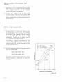
MAIN SYSTEM ADJUSTMENT
1. The jet needle and needle jet serve to control the _proper air/fuel rati_o, and thereby
engine performance, at partial loads ( 1/4 to
% throttle valve opening). The jet needle
tapers and the clearance between the
needle and needle jet increases as the
throttle valve opening increases.
The air/fuel ratio is controlled by the
position of the "E" ring that is inserted in
one of the five (5) slots on the head of the
needle. (See Fig. 2-21).
.....r- 2
::;:=!
2. The main jets provided with the carburetors
from the factory are:
} "E" RING
POSITIONS
+5-8%
4
32 mm (Brut 340)- 220
..r:::
34 mm (Brut 440) - 340
For richer or leaner engine operation under
special conditions, additional jet sizes are
available.
-s:'-
0
....u..
....
w
::J
u..
- 3- 6%
15
50
75
100(%)
THROTTLE VALVE OPENING
FIG. 2-21
2-12
SERVICE MANUAL - 1975 SCORPION BRUT
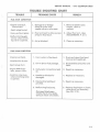
TROUBLE SHOOTING CHART
TROUBLE
(
-PROBABLE CAUSE
REMEDY
FUEL RICH CONDITION
-Engine noise dull,
intermittent
- Spark plugs fouled.
- Heavy exhaust gases
-Malfunctioning gets
worse, when enriching valve is opened.
1. Damage to or foreign
obstacle under inlet
needle valve or valve seat.
1. Remove needle valve.
Inspect, clean or
replace.
2. Float arm bent to allow excess
of fuel in float bowl.
2. Adjust float arm. (See
ADJUSTMENTS, P. 2-11)
3. Air jet blocked.
3. Clean as necessary.
FUEL LEAN CONDITION
-Engine overheats.
1. Ice or water in float bowl.
main jet and needle jet.
-Acceleration is poor.
(
1. Drain and clean float bowl,
2. Dirt in jets or fuel passage.
2. Disassemble carburetor and
clean.
-Engine RPM fluctuates, power is low.
3. Carburetor connections leak
air.
3 . Repair as necessary.
-Condition improves,
when enriching valve
is opened.
4. Needle jet blocked or
4. Replace as necessary.
-Spark plugs burn.
'
damaged.
5. Impulse line leaking or
5. Repair as necessary.
pinched.
6. Malfuncting fuel pump.
-Damaged diaphragm
-Intake check valve leaks.
-Exhaust check valve leaks.
6. Replace diaphragm or plastic
valve disc(s) as necessary.
(See FIG. 2-1 0).
2-13
(
l
1975
SCORPION
BRUT
(
Service Manual
Electrical
Section
3-1
SERVICE MANUAL - 1975 SCORPION BRUT
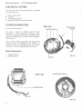
ELECTRICAL SYSTEM
The Scorpion Brut Electrical Sy stem i s divided
into four sections:
)
A. Power generation
B. Ignition
C. Voltage Regulation
D. Electrical Control and Distribution
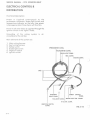
POWER GENERATION
BRUT 440
Functional Description:
LIGHTING COILS (4)
MAGNETIZED
ROTOR
AC power, used for lighting and controls
operation, is generated by rotating a p e rmanently magnetized flywheel mounted o n the
engine crankshaft past a stator which contain s
lighting coils.
The no load voltage generated, increases with
engine R.P.M. To safeguard the sy st e m, a
regulator limits the voltage level to 13-14 volt s
maximum. (See Voltage Regulation Section).
Main Elements:
1. Magnetic Rotor
2. lighting Coils
FIG. 3- 1
STATOR
BRUT 340
MAGNETIZED ROTOR
)
FIG. 3-3
3-2
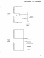
SERVICE MANUAL • 197 5 SCORPION BRUT
TAN
(
RED
LIGHTING
COILS
(STATOR)
YELLOW
RED
ENGINE
CONNECTOR
YELLOW
TAN
340 BRUT
FIG. 3-4
YELLOW
LIGHTING
COILS
(STATOR)
YELLOW
ENGINE CONNECTORS
440 BRUT
FIG. 3-5
(
3-3
SERVICE MANUAL - 1975 SCORPION BRUT
IGNITION
Functional Description:
The Brut engines utilize two different type ignition systems. The 340 engine is equipped with a
flywheel magneto type ignition. The 440 engine is equipped with an electronic Capacitive
Discharge Ignition System.
340 Engine Ignition:
MAIN ELEMENTS:
An e lectrical curren t is generated by rotating a
permanently magnetized flywheel about the
ignition coils. The current initiated in the coils
in turn energizes the primary coils of the external ignition coils. The secondary coils of the
external ignition coils are situated in the force
field generated by the primary coils.
1.
2.
3.
4.
5.
When the points close, causing an interruption
of the current flow through the primary winding, its force field immediately collapses and
generates a very high voltage in the second
coil. This voltage in the region of several
thousand volts will jump the spark plug gap
causing ignition to begin.
The collapsing lines of force cut through the
primary windings, raising the voltage in that
circuit also. As this occurs, the condenser absorbs the generated current to reduce the tendency to overload the points. As soon as th e
voltage level in the primary winding drops
below that of the condenser, current again
flows in the original direction, energizing the
system. This occurrence and the reversal happens several times eac h cycle creating a
powerful, long duration spark for more reliable
ignition.
Ignition Coils (Stator)
Condensers (2)
Breaker Points (2)
Ignition Coils (External) (2)
Spark Plugs (2)
IGNITION COILS
FIG. 3-6
)
FIG. 3-7
3-4
SERVICE MANUAL - 1975 SCORPION BRUT
(
'
IGNITION COIL (STATOR)
CONDENSER
Ht·
~SPARK
PLUG
EXTERNAL IGNITION COILS
--
~SPARK PLUG
FIG. 3-8
ENGINE CONNECTOR
340 BRUT
IGNITION SCHEMATIC
3-5
SERVICE MANUAL - 19.75 SCORPION BRUT
440 Engine Ignition:
Electrical energy (high voltage, low amperage) is generated by rotating a permanent magnet
flywheel past a pair of ignition coils. The high voltage (~200v) thus generated is absorbed by a
large condenser.
A special signal is also initiated by the rotating magnet which closes an electronic switch (tran sistor) every 120 degrees of rotation. When the transistor conducts, current flows from the con denser through the primary windings of the three external coils. The current rises abruptly as the
condenser discharges creating the necessary force field in the external coils, and falls just as
abruptly.
The voltage induced in the secondaries of the external coils rises so rapidly that it will exceed the
voltage necessary to jump the spark plug gap even when the plugs are fouled.
All three plugs "fires" simultaneously every 120 degrees. Timing of cylinder pressure, however,
determines which one of the three cylinders supports combustion.
The keyed relationship between the crankshaft and the rotor determines the timing of the
engine.
The timing is electronically advanced progressively from start-up to fully advanced at 4500
RPM. At 4500 RPM, the lead is between 3.2 and 3.5 mm. This corresponds to 16 degrees - 20
degree advance.
NOTE: The Brut 440 ignition schematic is not accurate physically, but only intended as a pictoral
representation of the ignition principles involved.
MAIN ELEMENTS:
1. Magneto Coils
a. Ignition Coils
CONDENSER
(CDI UNIT)
_L
(CDI UNIT)
,--------~-------..
_)
SPARK
TRANSISTOR
.,-----...
PLU(~
I•
b. Signal Coil
2. CDI Unit
COILS
3. External Coils
(MAGNETO)
4. Spark Plugs
SIGNAL COIL
(MAGNETO)
I·
BRUT 440 IGNITION
SCHEMATIC
EXTERNAL
COILS (3)
FIG. 3-9
J
3-6
SERVICE MANUAL • 1975 SCORPION BRUT
(
I
IGNITION COILS
-=---...-.. . .
-
-
(MAGNETO)
ROTOR ·- - -
----ENGINE CONNECTOR
(CD IGNITION)
........;;;:--,.....---·t:NGINE CONNECTORS
(LIGHTING COIL)
FIG. 3-10
CD IGNITION UNIT
---"::11
(CONTAINS CONDENSER)
~----- EXTERNAL COILS
(
CONNECTOR
\
:.1 - + - - - - - · - SAFETY SWITCH CONNECTOR
- ENGINE CONNECTOR
FIG. 3-11
, . . - - - - - - - - - - - - - - EXTERNAL COILS
CDI UNIT
"11'------ - SPARK PLUG LEADS
CONNECTOR
...
FIG. 3-12
3-7
SERVICE MANUAL • 1975 SCORPION BRUT
VOLTAGE REGULATION
Functional Description:
The voltage regulator is connected across the
lighting coils in parallel with the electrical load
of the sled. Under operating conditions, the
voltage drop across the regulator is such that
13.8 volts RMS is supplied to the snowmobile
lighting circuit.
FIG. 3-13
)
TRANSISTOR
SCR
MOUNTING
BRACKET
3-8
VOLT AGE REGULATOR SCHEMATIC
FIG. 3-14
SENSING
ELEMENT
SERVICE MANUAL - 1975 SCORPION BRUT
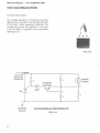
VOLTAGE REGULATOR CHECKS
(
1
1. Resistance across regulator
Two most common catastrophic failure modes of the regulator may be identified by simply
checking the resistance of the regulator.
a. Burned out sensing element.
Normal resistance across the regulator is approximately 155 - 160 . The symptom of a
burned out sensing element is a sig nificantly increased resistance reading.
b. Shorted SCR.
Shorted SCR is characterized by a sign ificantly reduced resistance reading.
2. Set point check
Use test circuit as shown below. Read voltage across regulator. Value should be 13.8
.5V.
±
(_)
100W
5..n.
120V
REGULATOR SET POINT TEST CIRCUIT
FIG. 3-15
c
39
SERVICE MANUAL • 1975 SCORPION BRUT
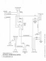
ELECTRICAL CONTROL &
DISTRIBUTION
Functional Description:
Power is supplied continuously to the
tachometer movement, brake light switch and
temperature indicator so that any time power
is being generated, those items will function.
Power to all other items is supplied through the
ignition switch in the "lights" mode.
Grounding of the wiring
complished at the roll bar.
system
is
ac-
Main elements of the system are:
1.
2.
3.
4.
5.
6.
Main wiring harness
Seat wiring harness
Safety switch
Brake light switch
High-Low switch
Ignition switch
SPEEDOMETER CONN.
TACHOMETER CONN.
HEAD LIGHT CONN.
REG. CONN.
ENGINE CONN.
_)
In .·
~.:
WAR~ING
LIGHT CONN.
tI
SAFETY
I
TAILLIGHT CONN.
SWITCH
CONN.
BRAKE LIGHT SW. CONN.
HI-LO SW. CONN.
IGNITION SWITCH
CONN.
;3-1 0
FIG. 3-16
,--..._
'
"""'\
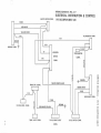
WIRING SCHEMATIC FIG. 3-17
ELECTRICAL DISTRIBUTION & CONTROL
197 5 SCORPION BRUT 340
SAFETY SWITCH CONN.
r--
·....--
WHITE
r---~/
I
RED/WHITE
.-/'-
YELLOW /WHITE
1'\
Y/W
TACHOMETER CONN .
.--
I
Y/W
BROWN
ENGIN~NN.
R/W
OJ:-
r--
w
IGNITION
SWITCH
CONN.
z
CONN.
7
7'-
1
SPEEDOMETER
Y/W
I
I
Y/W/B
r
3:
0
Ill::
111:1
/Ir--
111:1
'
~
>
•fl
BROWN
7
~
m
3:
)>
z
c:
GREEN/WHITE
BLUE
Y/W
L--
HEADLAMP CONN.
Y/W/B
BROWN
....
w
VOLT AGE REG. CONN.
I
w
I
TEMP. LIGHT CONN.
r-
Cll
"""'
,,,
RED/WHITE/YELLOW
>
)>
-o
3:
....0
m
n
YELLOW /WHITE/BLACK
BRAKE SW. CONN.
C/)
;:a
C/)
I
l'
TAIL & BRAKE LIGHT
(
n
0;:a
]
HI-LO SWITCH CONN.
"tt
0
.,z
;:a
CONN.
c:
-4
SERVICE MANUAL - 1975 SCORPION BRUT
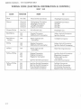
WIRING CODE (ELECTRICAL DISTRIBUTION & CONTROL)
BRUT 340
COLOR
FUNCTION
FROM
TO
Blue
Hot (Hi)
Hi-Lo Switch Connector
Head l ight Connector
Brown
Ground
Ground
Ground
Ground
Tachometer Connector
Headlight Connector
Taillight Connector
Engine Connector
Headlight Connector
Roll Bar
Roll Bar
Roll Bar
Green/White
Hot (Lo) ·
Hi -Lo Switch (Lo)
Headlight (Lo)
Red/White
Hot
Hot
Engine Connector
Safety Switch Connector
Safety Switch Connector
Ignition Switch
Red/White/
Yellow
Hot
Brake Light Switch
Connector
Taillight Connector
White
Hot
Hot
Engine Connector
Safety Switch Connector
Safety Switch Connector
Ignition Switch Connector
Yellow
Hot
Brake Light Switch
Connector
Heat Warning Indicator
Yellow/White
Hot
Hot
Hot
Engine Connector
Engine Connector
Regulator Connector
Hot
Ignition Switch Connector
Ignition Switch Connector
Regulator Connector
Brake Light Switch
Connector
In strument Connector
Hot
Hot
Hot
Hot
Ignition Switch Connector
Ignition Switch Connector
Hi -lo Switch Connector
Tachometer Connector
Taillight Connector
Hi-Lo Switch Connector
Tachometer Connector
Speedometer Connector
Yellow/White
Black
3-12
)
,.
'
,.._
~
..........
'-~
SAFETY SWITCH CONN.
I
ENGINE CONN.
c:::J--I
I
BLACK
YELLOW /WHITE
1
I
J
-"'I I~II
!
r-
TACHOMETER CONN.
.
Yffl
YELLOW /WI-IlTE
BROWN
y ffl/B
r--
I
BLACK
IGNITION
SWITCH
CONN.
Yffl
I
Y/W
~
I
:
/~
SPEEDOMETER
CONN.
z
3:
0
1111:
CCI
/~
r--
•II
BROWN
/
"'m
;:a
YELLOW /WHITE/BLACK
<
BRAKE SW. CONN.
I
L
0
....
....
VOLTAGE REG. CONN.
I
I
TEMP. LIGHT CONN.
WIRING SCHEMATIC FIG. 3-18
Cf
w
ELECTRICAL DISTRIBUTION & CONTROL
197 5 SCORPION BRUT 440
I
3:
'--HEADLAMP
CONN.
BROWN
RED/WHITE/YELLOW
I.LI
>
m
BLUE
y ffl/B
3:
n
GREEN
II·
)>
z
c:
)>
r-
-o
......
J
TAIL & BRAKE LIGHT
CONN.
~
HI-LO SWITCH CONN.
(II
"'
n
0;:a
.,
0
z
CCI
;:a
c:
-t
SERVICE MANUAL - 1975 SCORPION BRUT
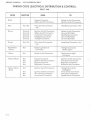
WIRING CODE {ELECTRICAL DISTRIBUTION & CONTROL)
BRUT 440
COLOR
FUNCTION
Black
FROM
TO
Engine Connector
Safety Switch Connector
Safety Switch Connector
Ignition Switch Connector
Blue
Hot (Hi)
Hi-Lo Switch Connector
(Hi)
Headlamp Connector (Hi)
Brown
Ground
Ground
Ground
Ground
Ground
Ignition Switch Connector
Safety Switch Connector
Instrument Connector
Headlamp Connector
Taillight Connector
Safety Switch Connector
Ground (Roll Bar)
Headlamp Connector
Ground (Roll Bar)
Ground (Roll Bar)
Green
Hot (Lo)
Hi-Lo Switch Connector
(Lo)
Headlamp Connector (Lo)
Red/White/
Yellow
Hot
Brake Light Switch
Connector
Taillight Connector
(Brake Light)
Yellow
Hot
Brake Switch Connector
Temperature Light
Connector
Yellow/White
Hot
Hot
hot
Hot
Engine Connector
Ignition Switch Connector
Engine Connector
Regulator Connector
Ignition Switch Connector
Instrument Connector
Regulator Connector
Brake Switch Connector
Yellow/White
Black
Hot
Ignition Switch Connector
Hot
Hot
Hot
Ignition Switch Connector
Hi-Lo Switch Connector
Instrument Connector
Taillight Connector
(Taillights)
Hi-Lo Switch Connector
Instrument Connector
Speedometer Connector
)
'
)
3-14
SERVICE MANUAL - 197 5 SCORPION BRUT
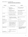
TROUBLE SHQ,QTING (ELECTRICAL)
(
)
TROUBLE
No lights
PROBABLE CAUSE
REMEDY
Open Circuit:
Faulty Switch(s)
Separated Connector(s)
Cut Wiring
Repair or replace faulty
or damaged element.
Wiring shorted to ground:
Damaged Insulation
Repair or replace damaged
or faulty element.
Faulty Regulator (Shorted SCR)
Replace regulator.
Shorted or open lighting coil.
Replace stator plate.
Faulty regulator- Incorrect
regulator set point (too low).
Replace regulator.
Faulty regulator - burned out
regulator sensing element.
Incorrect Set Point (too high).
Replace regulator and failed
bulbs.
Burned out
lights (individual)
Failed bulb.
Replace bulb.
Burned out lights
Intermittent short in wire harness.
Repair or replace wire harness.
Engine won't run
1. Open or shorted windings in
1. Replace armature plate.
Weak or no
spark
ignition coils (stator).
2. Open or shorted windings.
in external ignition coil.
3. Shorted condenser- dirty or
worn.
4. Damaged (burned) points.
4 . Replace points.
1. Burned or fouled plugs.
1. Replace plugs. Determine that
Dim lights
Burned out
lights (all)
Engine won't runAdequate spark.
2. Replace external coil.
3. Replace condenser.
correct plugs are being used .
CHECK ENGINE TROUBLE
SHOOTING.
2. See Engine Trouble Shooting
Section
Unacceptable
Engine Performance
See Engine Trouble Shooting
Section
(
3-15
1
' )
1975
Scorpion
Brut
(
)
Service Manual
Clutch/Drive
Section
4- 1
SERVICE MANUAL- 1975 SCORPION BRUT
DRIVE SYSTEM
Functional Description:
The main elements included in this system ore:
1. Drive Clutch
2 . Drive Belt
3. Driven Clutch
4. Chain Case with sprockets, chain and chain tensioners.
5. Drive shaft with track drive sprockets.
The power from the engine is transmitted through this system to the track in
sequence of elements listed above to propel the machine.
The drive clutch, belt and driven clutch serve as a torque converter. The torque
converter on the snowmobile "down shifts" to a lower ratio as the track load increases as readily as it "up shifts" when the track load decreases.
To accomplish the automatic shifting, the movable sheave of the driven clutch
is fitted with a helical romp which is guided by a follower. This sheave is controlled by a spring pre-stressed in torsion and compression to hold the sheaves
together at the maximum pitch diameter. The drive clutch cover has a set of
centrifugal weights and helical romps. The drive movable contains a mating set
of romps (followers). A spring automatically positions the movable drive clutch
at the minimum pitch under zero and idle speed conditions.
Under acceleration, the torque from the engine is greater than the demand
from the track. As RPM increases, the weight arms move to force the movable
in (away from the cover). At the some time, the belt tension and belt friction on
the movable sheave results in a relative rotational motion between the cover
and the movable such that the cam action also forces movable away from the
cover.
The wedging action of the drive sheaves forces the belt outward in the driven
clutch.
Belt tension and wedging action are greater than spring forces of the driven
clutch and the sheave faces are wedged open against the helical cam. This action winds up and compresses the spring.
Under steady running, all forces are balanced and the belt chooses a ratio at
which this balance exists.
Under deceleration, the driven stationary stalls slightly. The belt tension and
friction on the driven movable plus spring torsion, moves the movable along
the ramp, closing it and forcing the belt out to a greater pitch diameter. This action increases belt tension. Wedging action opens the drive movable against
the weights down the ramps to a new lower pitch diameter for the drive clutch
until forces are again equalized.
4-2
)
SERVICE MANUAL - 1975 SCORPION BRUT
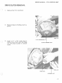
DRIVE CLUTCH REMOVAL
)
1.
Remove the 7/16 clutch bolt.
2.
Remove large nut holding clutch to gether.
3.
Insert a %II x 3 V4 steel plug in
hollow drive clutch hub. Use large
nut with plug as puller to remove
clutch.
11
7 /16" CLUTCH BOLT
)
II
CLUTCH ASSEMBLY NUT
STEEL PLUG
0
ASSEMBLY NUT
...
4 -3
SERVICE MANUAL· 1975 SCORPION BRUT
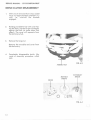
DRIVE CLUTCH DISASSEMBLY
1.
With clutch removed from sled, install
large nut approximately one-half { 1/2)
way, i.e., one-half the threads
engaged .
2.
Holding movable firmly with cover facing the floor, rap the large nut sharply
against the floor (or some other firm
object). The cover will separate from
the stationary hub.
3.
Remove the large nut.
Remove the movable and cover from
the stationary.
4.
Completely disassemble clutch. (Reverse of assembly procedure, which
see).
ASSEMBLY NUT
MOVABLE
SHEAVE
STATIONARY
SHEAVE
COVER
J
\ .,
l
t
/ Q1',\
I
r .
J
~/
OWJJ.
FIG. 4-4
r )
4 -4
SERVICE MANUAL • 1975 SCORPION BRUT
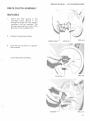
DRIVE CLUTCH ASSEMBLY
(
MOVABLE
1.
Insert the idl er spring i n the
movable bore. Shove it far
enough through that the keeper
(retainer) can be installed. Th e
spring tang must be in one of th e
grooves in the movable bore.
2.
Position the spring r etainer.
SPRING TANG
3.
FIG. 4-5
GROOVE
Pu sh the spring back up against
the retainer.
In sta ll the plastic bushing.
(
'
\
\
"''
\
FIG. 4-7
4-5
SERVICE MANUAL - 1975 SCORPION BRUT
4.
Place washer on nylon bushing.
)
CLUTCH COVER
FIG. 4-8
l.
Insert the bushing with washer in
weight arm.
BUSHING
NYLON
NOTE: The nylon washer always
goes on the clockwise side of the
weight arm when viewed looking
into the clutch cover.
SHOE
PAN HEAD SCREW
2.
W~SHER
I
)
1
0
Install weight arm in cover, securing it with bolt.
FIG. 4-9
FIG. 4-10
4 -6
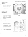
SERVICE MANUAL - 1975 SCORPION BRUT
CLUTCH (COMPLETE)
)
1.
2.
Place the movable sheave on the
stationary sheave. Engage the inner spring tang in the hole in the
stationary hub.
Prepare the cover with a rubber
band, holding the weight arms
correctly. Insure that the shoes on
the weight arms are all properly
oriented.
HOLE
I
FIG. 4-12
INNER TANG
Place cover over movable.
CORRECT SHOE ORIENTATION
()
INCORRECT ORIENTATION
RUBBER BAND
FIG. 4-13
FIG. 4-14
4 -7
SERVICE MANUAL • 1975 SCORPION BRUT
Make sure that the index marks
on rim of the movable and cover
are aligned.
FIG. 4-15
INDEX MARKS
3.
Secure clutch together with large
nut.
Remove rubber band.
FIG. 4-16
4-8
SERVICE MANUAL· 1975 SCORPION BRUT
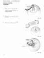
DRIVEN CLUTCH
REMOVAL
(.
1.
2.
Remove screw and lock wa sher,
securing clutch to Jack Shaft.
Pull clutch off shaft.
DRIVEN CLUTCH
DISASSEMBLY
1.
(
Wind the movable sheave against
the spring approximately 1/6
turn, and restrain it. Compress
cam top against clutch spring.
Slide cam in on stationary splined
hub until locking inserts clear the
cam top hub.
SCREW
(SECURING CLUTCH TO JACK SHAFT)
)
CAM TOP
2.
Remove locking inserts.
3.
Allow cam top to move off the
splined stationary hub slowly.
LOCKING INSERTS
SPRING
~
~' ~
,._
Be careful, since the spring is under both compression and wind
up, that the cam does not fly off
or rotate rapidly from spring wind
up.
4.
All parts of driven clutch can
then be separated.
FIG. 4-18
STATIONARY SHEAVE
MOVABLE SHEAVE
4-9
SERVICE MANUAL • 1975 SCORPION BRUT
DRIVEN CLUTCH
ASSEMBLY
1.
Place washer on stationary hub.
Install movable
stationary sheave.
2.
sheave
on
Place clutch spring over hub of
movable.
FIG. 4-18
3.
Insert the spring tang in the #2
hole (340). or #1 Hole (440).
)
FIG. 4-19
'
/
FIG. 4-20
4- 10
SERVICE MANUAL - 1975 SCORPION BRUT
4.
Place the cam top over the end of
the spring.
5.
Engage the spring end behind one
of the cam lobes.
6.
Rotate to cam top approximately
130 degrees. This will wind up the
spring.
(
The movable must be restrained
during this step.
7.
Push the cam top down over the
splines to clear the locking insert
groove.
FIG. 4-21
CAM LOBE
8.
(
Install inserts.
Release the clutch. The cam top
will snap back until the cam
ramps are engaged.
SPLINES
(';
FIG. 4-22
4- 111
SERVICE MANUAL - 197 5 SCORPION BRUT
CLUTCH INSTALLATION
DRIVE CLUTCH
1.
Place the drive clutch over the
engine PTO shaft with .010 shim
between clutch bore and shaft. In sure that there is no lubrication
on the shaft or in the clutch bore.
2.
Insert the clutch attach bolt. (See
Fig . 4-1 ) .
Torque to 75Ft. lbs.
DRIVEN CLUTCH
1.
With the Jack Shaft in position,
slide the driven clutch assembly
on the end of the shaft.
2.
Secure the clutch assembly on the
shaft with attaching screw and
lock washer. (See Fig. 4 -17) .
(_
' 1.-12
SERVICE MANUAL - 1975 SCORPION BRUT
CLUTCH ALIGNMENT
(
-.............
,"'
)
1.
With both clutch assemblies installed, m easure alignment of the
back sides of the stationary
sheaves.
) ..
,
"
-·
-
?
They should be parallel, and off
set by V2 ". (See Fig. 4 -23).
ALIGNMENT BAR
2.
( )
If the sheaves are not parallel,
loosen the mounting bolts on the
chain case and rotate the chain
case to bring the sheaves into
parallelism.
ADJUSTMENT SLOTS
FIG. 4-24
CHAIN CASE MOUNTING BOLTS
n
4 - 13
SERVICE MANUAL- 1975 SCORPION BRUT
3.
If the off set is not correct, i.e., is
not V2 ", remove the driven clutch
and insert or remove spacer
washers on end of shaft to
provide the correct off set.
SPACING WASHER
FIG. 4-25
JACK SHAFT
)
DRIVE CLUTCH
ADJUSTMENT
The cut-in speed of the BRUT clutch is
3800- 4200 rpm. The control speed is
7000 to 7200 rpm.
To vary the shift range of the machine,
add or subtract washers on the pan
head screws on the weight arms.
(See Fig. 4-9).
(_.)
4-14
SERVICE MANUAL· 1975 SCORPION BRUT
BRAKE REMOVAL
CABLE BRACKET
()
1.
Remove attaching bolts.
2.
Separate control cable
clevis and cable bracket.
3.
Pull brake disc off
splines.
from
jack shaft
DISASSEMBLY
1.
Remove cotter pin and castillated
nut. Brake assembly can then be
separated into component parts.
FIG. 4-26
CLEVIS
ATTACHING BOLTS
ASSEMBLY
(
1.
Insert steel plate and wear pad
into recessed area in back of
castings.
STEEL PLATE
J
'
FIG. 4-27
4 - 15
SERVICE MANUAL· 1975 SCORPION BRUT
2.
Place pins in casting holes, rounded end out.
\
_.)
3.
Position lever over threaded stud
and washer on top of lever.
4.
Install castillated nut and cotter
pin.
INSTALLATION
FIG. 4-28
PINS
DEND
1.
Reverse of removal. (See Fig. 4-
26).
A
--
~,.:
)
WASHER
FIG. 4-29
LEVER
FIG. 4-30
4- 16
NUT & COTTER PIN
FIG. 4-31
1975
Scorpion
Brut
( )
Service Manual
Suspension
Section
0·
.
.
5- l
SERVICE MANUAL - 1975 SCORPION BRUT
SUSPENSION SYSTEM
Functional Description:
The four main e lem ents of a snowmobile suspen sion ore:
1.
2.
3.
4.
Skis
Track Suspension
Seat
Operator
All elements work together to perform the sus pension functions to the optimum degree.
The suspensions ore basically designed to:
1.
2.
3.
4.
Protect the operator from physical abuse or
injury.
Keep the operator from being ejected from
his operating position and controls.
Prevent damage to the machine.
Increase ground contact and improve trac tion.
The track suspension, on the 1975 Scorpion Brut, is a slide (unit type) suspension, especially designed with the following characteristics:
1.
Rugged construction for all out performance.
2.
Fully adjustable to suit the operator's n eeds under all conditions.
3.
Dampening provided by a cam operated friction disc shock absorber.
4.
Attachable road wheel option for marginal snow.
FIG. 5-1
I
J
WHEELS
TIE DOWN
ROD NUTS
5 -2
SUSPENSION SLIDE
TRACK
INTERNAL TRACK DRIVE SPROCKET
\
SERVICE MANUAL- 1975 SCORPION BRUT
SUSPENSION SYSTEM
REMOVAL
Th e e lements of the suspension/drive
must be removed in th e following
sequence:
1.
2.
3.
Slide suspension
Chain and chain sprockets
Drive shaft
SLIDE SUSPENSION
REMOVAL
\.......t
1.
Place the sled on th e floor with a
2 " x 4" underneath the track.
Plac e weight on the sled to extend the cross shaft.
2.
Remove the r ea r mounting
screws . Relea se w e ight.
3.
Remove lock ing bolts, locks, and
front mounting bolt s.
4.
Plug bl eed hole in gas cap. Turn
machine on its sid e . Pull suspe nsion out.
FRONT MOUNTING BOLTS
(WITH LOCKING DEVICE)
FIG. 5-2
5·3
SERVICE MANUAL - 197 5 SCORPION BRUT
CHAIN DRIVE REMOVAL
l.
Re move chaincase cover.
2.
Remove chain drive components.
a . Remove snap ring on uppe r
sprocket.
b . Re move bolt on lower
sprocket.
c. Back out chain t e n sion tighte ning bo lt.
•..
d. Sl ide sprockets and chain out
toge ther.
CHAIN TENSION TIGHTENING BOLT--
- - --
,_
I
-
- - - -- -
(
...
FIG. 5-3A
LOWER SPROCKET
BOLT---- -----~---'
CHAIN CASE MOUNTING BOLTS (4) --- ----~
.- FIG 5-38
~
5-4
SERVICE MANUAL • 1975 SCORPION BRUT
REMOVE FRONT DRIVE
(
1.
Loosen allen screw in collar on
left end of shaft just inside chaincase.
2.
Rotate collar to loosen.
3.
Slide collar over shaft.
4.
Loosen chaincase mounting bolts.
5.
Push shaft into chaincase hole.
6.
Lower opposite end of shaft and
pull out of tunnel.
FIG. 5-4
LOCKING COLLAR
SUSPENSION DISASSEMBLY
SPROCKET MOUNTING BOLT
1.
Remove 5/16" bolts securing
sprockets to shaft. (See Fig. 5-4) .
2.
Slide sprockets off shaft.
c
5-5
SERVICE MANUAL· 1975 SCORPION BRUT
SLIDE SUSPENSION
1.
loosen spring adjusting eyebolts.
Remove springs.
2.
Remove cotter pin, castellated
nut and cross bolt. Pull shock
assembly out of slide assembly.
(See Fig. 5-6).
3.
Additional disassembly of the
slide suspension may be accomplished by removing shafts
which hold the:
a. front idlers
b. rear idlers
c. front mounting weldment
(torque arm weldment)
J
FRONT IDLERS
TORQUE ARM
WELDMENT
-
---r-----t
---:----~__,·111
EYEBOLT---------~
SUSPENSION SPRINGS- - · --
-
---
REAR IDLERS----+\·
FIG. 5-5
u
5-6
SERVICE MANUAL- 1975 SCORPION BRUT
()
FIG. 5-6
FIG. 5-7
FIG. 5-8
ASSEMBLY /INSTALLATION
Assembly and installation is accomplished in reverse order of removal and
disassembly.
(_;
5·7.
0