1
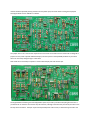
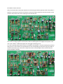
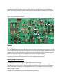
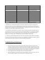
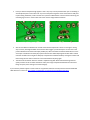
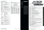
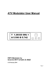
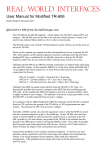
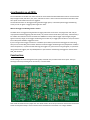
circuitbenders.co.uk CB55.
The circuitbenders.co.uk CB55 is an exact clone of the voice board of the Boss DR55 drum machine. It features four
fully analogue sounds, bass drum, hat, snare, and rimshot. There is also an overall accent feature that adds a little
extra punch to the whole mix when it is triggered.
The sounds and accent can be triggered using standard trigger pulses, or with the optional trigger conditioning
circuit you can use gates or trigger pulses longer than 10ms.
What is the trigger conditioning and do I need it?
The CB55 voices are triggered using standard 5v trigger pulses that last for 10ms. Any longer than that and you
may experience double triggering and flam sounds, any shorter and the sounds decay incorrectly. Unfortunately a
lot of older drum machines such as the TR707 and TR606 have a fairly random trigger output length, and gate
signals can be any length, so the trigger conditioning circuit takes any 5v trigger pulse of 10ms or more, and turns it
into a 10ms pulse suitable to trigger the voices.
If you're using a midi to trigger convertor or a modular system where you know that the triggers are 10ms long,
then you can use the TRIG_IN2 connector and leave out all the trigger conditioning circuit (components marked in
red on the parts list). If you don't know how long your triggers are, you want to use 5v gate signals, or you will be
using a mixture of triggers, then its probably better to just install the conditioning and trigger the sounds via the
TRIG_IN1 connector.
Construction:
The first thing to do is read through this entire guide, and make sure you have all the correct parts. Then you
should get started by installing all of the resistors, as shown below:
Next install the diodes and the jumper links. The diodes need to be correctly oriented so that the band around one
end of the component body is at the same end as the band shown on the board. D1 is a larger 1N4001
rectifier diode that provides polarity protection for the power input, but all the others can be general purpose
small signal diodes such as 1N4148's or 1N914's.
The jumper wires at J3-J7 connect the output of each voice circuit to the main mix bus. These links are designed as
jumpers for easy mods to provide individual outputs, but at this point it would probably be better to just install
them. You can always change things at a later date.
Next install the non-electrolytic capacitors. These include the poly film and ceramic caps.
The original DR55 used those green resin dipped film caps that you find in just about everything from that era. If
you wanted to use them for some reason they will work fine, although sound-wise they are exactly the same as the
box caps we've used here. The 47pF cap at C16 will probably have to be ceramic, as alternative types tend to not
be available in values that small.
Next you should install the electrolytic capacitors. Be careful you get these the right way round as the polarity is
important. The positive pin is shown on the board. C1 and C3 should be rated for at least 25v minimum, but the
rest don't really matter that much as anything over 10v should be fine.
Now install the voltage regulators and transistors. REG1 is a 78L06 regulator that supplies the 6v power to the
voice circuits. REG2 is a 78L09 that supplies 9v to the trigger conditioning circuit.
T1 to T10 are general purpose NPN transistors. Roland/Boss used 2SC945's is virtually everything they produced
during this era, so this is what we've specified here, but you could probably get away with using any number of
transistors with similar specs. We haven't actually tried it, but we would imagine it'd also work fine with the
common 2N3904 or 2SC1815.
Q1 in the accent circuit should be a JFET transistor with a DSG pinout. A few different types will fit here. We've
tried the J201, MPF102 and 2N5457, and they all seem to work okay. The DR55 actually uses a 2SK30AY in this
position. This will also work but you'll have to check the pinout and rotate the part accordingly. The correct DSG
pin positions are marked on the board.
Next install the trimmer pots at VR1 and VR2, the inductor at L1, the LM324 quad opamp, and any pin headers you
want to use for the off board connections.
Power:
The board is powered by 12v DC. On the bottom left of the board you can see a 2x5 pin power connector. Only the
pins on the right labeled with the larger GND and +12V text are actually used, but the 10 pin connector is provided
for the standard eurorack format. Please note that due to its size, this PCB is not designed specifically to be used in
a modular system module, but we used this connector just in case somebody wanted to try and bodge something
together. In normal use you can just use the GND and +12V connections with the larger font.
If you haven't installed the trigger conditioning circuit then you will have left out the 9v regulator. In this case you
can run the voice circuits from a 9v input instead of 12v if you wanted to. Either will be fine.
Inputs, outputs and pots:
The wiring diagram for the inputs, outputs and pots can be found on the next page.
The diagram shows all the pots viewed from above. The accent amount pot should ideally be an antilog pot,
commonly known as a C curve pot, but a linear B curve pot can be used at a push, or a normal A curve log pot if
you use the left hand pin and wire it in to operate backwards. You can use a 470K pot if you are in Europe and
500K is not readily available.
Note that the pin assignations for the two TRIG IN connectors are different.
Notes:
For best effect, the timing of the accent trigger has to be very tight with the voice triggers. If the accent trigger
occurs too soon before, or too late after the voice triggers you may experience flam or clicking sounds. If your midi
to trigger converter has a dedicated accent output, then make sure you use that for the accent trigger input, as it
will usually be less prone to midi lag. Triggers from a purely analogue system will usually have tighter timing than
midi.
If you are using gate signals to trigger the CB55 instead of trigger pulses, the accent will stay activated for as long
as the input gate remains high.
You should only ever use 5v trigger pulses or gate signals. Anything higher than 5v will cause unwanted effects and
may damage the circuit.
Parts List:
Part numbers in RED are not required if you are not installing the trigger conditioning circuitry. See the build guide
for more details.
PART NUMBER
R1, R3, R4, R8, R10, R11, R14, R16,
R17, R21, R23, R24, R39, R74, R84
R2, R9, R15, R22, R46. R61, R72, R73
R5, R7, R12, R18, R20, R25
R6, R19, R32, R44, R51, R57, R59,
R60, R62, R69, R71, R81
R13, R26
R27, R78
R28, R29, R30, R35, R41, R42, R47,
R49
R31, R43, R50, R56, R64, R65, R68,
R76, R80
R33
R34
R36, R63, R77, R79, R82
R37, R53
R38, R40, R54
R45
R48
R52
R55
R58, R66, R70
R67
R75
R83
C1, C3
C30, C39, C43
C38, C41, C44, C46
C40
C42
C5, C6, C7, C8
C2, C4,
C9, C10, C11, C12
C13, C33
C14, C26
C15
C16
C17, C19
C18, C20, C25, C31, C36
C21, C22, C23, C35
C24, C28
C27
C29, C32, C37
C34
PART VALUE
100K
47K
27k
10K
NOTES
All resistors standard ¼ watt carbon,
or metal film
12K
680K
22K
2.2M
820R
220K
1K
150K
33K
270R
470K
330R
120K
1M
82K
68K
100R
10uF
22uF
4.7uF
0.15uF
47uF
100nF
100nF
68nF
47nF
27nF
2.7nF
47pF
1.5nF
2.2nF
6.8nF
4.7nF
5.6nF
1nF
18nF
Electrolytic 25v or more
Electrolytic
Electrolytic
Electrolytic or tantalum. *
Electrolytic
Poly Film
Ceramic
Poly Film
Poly Film
Poly Film
Poly Film
Ceramic unless Poly Film is available
Poly Film
Poly Film
Poly Film
Poly Film
Poly Film
Poly Film
Poly Film
C45
D1
D2, D3, D4, D5, D6, D7, D8, D9
T1, T2, T3, T4, T5, T6, T7, T8, T9, T10
Q1
REG1
REG2
L1
IC1
J3, J4, J5, J6, J7
VR1
VR2
TONE
VOLUME
ACCENT
TRIG_IN 1, TRIG_IN 2, POWER
CONNECTIONS, OUTPUT
1.8nF
1N4001
1N4148 or 1N914
2SC945
J201 / MPF102 / 2N5457
78L06
78L09
47mH inductor
LM324
Wire links
50K
10K
1MA
10KA
500KC
PIN HEADERS
Poly Film
Rectifier diode
Or similar small signal diode
Or similar transistor
Many DSG JFET’s work here, or
others according to pinout
6v regulator
9v regulator
Original DR55 uses 45mH **
Quad opamp
Individual voice outputs ***
Accent level trimmer pot
Noise level trimmer pot
Tone pot
Volume pot
Accent amount pot.
You can use standard pin headers in
any of these connections.
* The DR55 uses a 0.15uF tantalum cap here. There doesn’t seem to be a particular reason for this
choice, so we can only assume the original designer wanted to use a polarized cap but couldn’t get an
electrolytic with a value that small. Either an electrolytic or a tantalum will work fine, but a tantalum will
probably be a lot more difficult to get hold of these days.
** The DR55 uses a 45mH inductor in the Hi-Hat. These are virtually impossible to get hold of, but you
can substitute a 47mH, or even a 43mH one with no perceptible difference. The original part probably
had a tolerance of +/-20% of the stated value anyway, so 2mH off in either direction won’t make a
difference to the sound. A Bourns RLB0812-473KL or Murata 22R476C will do the job.
*** These links connect the output from each voice circuit to the mix bus. They have been provided as
links rather than permanent PCB traces to allow for easy modding for individual voice outputs. Pieces of
cutoff component leg can be used here. You should have plenty lying around.
Troubleshooting and adjustment:
If you are having problems, please check the following:
•
•
•
•
•
Parts orientation: The electrolytic capacitors and the diodes need to be soldered in with the correct
orientation. The capacitors will have the negative pin marked on their body, and the positive pin marked
on the board. Diodes will have a band on one end of their body. This band is marked on the board image.
Have you got the power the right way around and are you using the correct GND and +12V connections?
Do you have the transistors the right way round? Is the FET at Q1 of the correct type?
Are your trigger pulses the correct length? See the start of this guide for details.
Check your soldering on any joints that connect to the ground plane on the rear of the board. These are
often more difficult to solder due to the heatsink effect of the ground plane itself.
•
Have you shorted component legs together? This is very easy to do by accident when you are soldering in
several adjacent parts at the same time. If you have component legs bent across each other to hold parts
in place during installation, make sure that once you have soldered them in and cut off the excess leg, the
remaining legs are not in contact with each other. See the images below for details.
Crossed component legs during installation
•
•
Shorted legs after soldering
VR1 sets the difference between the normal and accented output levels. Theres no real right or wrong
way to set this, although the DR55 service manual does suggest you should adjust it to read 4.5v at the
junction between R75 and the VR1 wiper (middle pin). What we would recommend would be to turn the
accent pot to maximum and them play a pattern with accents while adjusting VR1 for best effect. Please
note that the effect of turning VR1 is delayed, so adjustments should be made by moving the trimmer and
then leaving the new value to settle for a few seconds before adjusting again.
The noise level for the hat and snare sounds is adjusted using VR2. We'd recommend using a decent
quality trimmer for this as theres sometimes a fairly thin range of adjustment between the noise level
being too quiet, and it starting to resonate strangely.
If you need any further support or want to discuss any potential mods for this PCB, we have started a dedicated
CB55 board on our forum at: http://www.circuitbenders.co.uk/forum/index.php/board,32.0.html