1
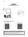
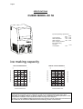
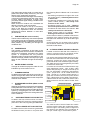
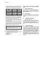
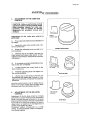
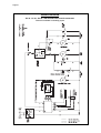
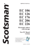
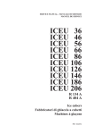
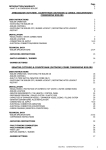
Page 1
Page 1
SERVICE MANUAL
EC 46
EC 56
EC 86
Cubers
with storage
SCOTSMAN EUROPE - FRIMONT SPA
Via Puccini, 22 - 20010 Pogliano M.se - Milano - Italy
Tel. +39-02-93960.1 (Aut. Sel.)- Telefax +39-02-93550500
Direct Line to Service & Parts:
Phone +39-02-93960350 - Fax +39-02-93540449
ISO
900
1-C
Website: www.scotsman-ice.com
ert.
n. 0
080
E-Mail: [email protected]
MS 1000.94 REV. 03/2006
Page 2
INDICE
Page 2
Table of contents
Specifications EC 46
Specifications EC 56
Specifications EC 86
page
2
3
5
7
GENERAL INFORMATION AND INSTALLATION
Introduction
Unpacking and Inspection
Location and levelling
Electrical connections
Water supply and drain connections
Final check list
Installation practice
9
9
9
9
10
10
11
OPERATING INSTRUCTIONS
Start up
Operational checks
12
12
OPERATING PRINCIPLES (How it works)
Freezing cycle
Harvest cycle
Electrical sequence
Components description
13
13
17
17
ADJUSTMENT, REMOVAL AND REPLACEMENT PROCEDURES
Adjustment of the cube size
Wiring diagram
Service diagnosis
20
21
22
MAINTENANCE AND CLEANING INSTRUCTIONS
General
Icemaker
Clean - Replace of air condenser filter
Cleaning instructions of water system
24
24
24
24
Page 3
Page 3
SPECIFICATIONS
CUBER MODEL EC 46
Important operating requirements:
MAX.
40°C
35°C
5 bar
MIN.
Air temperature
10°C
Water temperature
5°C
Water pressure
1 bar
Electr. voltage variations
from voltage rating
specified
on nameplate
-10%
+10%
ice making capacity
WATER COOLED MODELS
AIR COOLED MODELS
°C
o
°C
o
Kg.
25
10
23
21
22
21
20
32
19
18
38
17
ICE PRODUCED PER 24 HRS.
24
AMBIENT TEMPERATURE
ICE PRODUCED PER 24 HRS.
10
16
24
23
21
22
32
21
20
38
19
18
17
AMBIENT TEMPERATURE
Kg.
25
16
32
27
21
15
WATER TEMPERATURE
10 o°C
32
°C
°F
27
21
15
10 o°C
WATER TEMPERATURE
NOTE. With the unit in "built-in" conditions, the ice production is gradually reduced in respect to the
levels shown in the graf, up to a maximum of 10% at room temperatures higher than 32°C.
The daily ice-making capacity is directly related to the condenser air inlet temperature, water
temperature conditions of the condenser air filter and age of the machine.
To keep your SCOTSMAN CUBER at peak performance levels, periodic maintenance checks must
be carried out as indicated on Maintenance and Cleaning section of this manual.
Page 4
Page 4
SPECIFICATIONS
Dimensions:
HEIGHT
WIDTH
DEPTH
WEIGHT
645 mm.
386 mm.
600 mm.
42 Kgs.
EC 46 - CUBER
machine specifications
Model
Cond. unit
Finish
Comp. HP
Air
Water
Stainless steel
1/4
EC 46 AS 6
EC 46 WS 6
Basic electr.
Amps
Start
Amps
.
Watts
230/50/1
2.1
12
400
Cubes per harvest: 18 medium
* A 15°C water temperature
Bin
Capacity
9 Kg.
Electric power cons.
Kwh per 24 Hr
8
6
Nr. of wires
3 x 1.5 mm2
Water req.
lt/24 HR
77*
350*
Amps fuse
10
Page 5
Page 5
SPECIFICATIONS
CUBER MODEL EC 56
Important operating requirements:
MIN.
Air temperature
10°C
Water temperature
5°C
Water pressure
1 bar
Electr. voltage variations
from voltage rating
specified
on nameplate
-10%
MAX.
40°C
35°C
5 bar
+10%
ice making capacity
WATER COOLED MODELS
°C
o
Kg.
10
21
30
28
32
26
38
24
22
ICE PRODUCED PER 24 HRS.
33
AMBIENT TEMPERATURE
ICE PRODUCED PER 24 HRS.
°C
o
Kg.
32
10
32
31
30
21
32
29
38
28
27
26
25
AMBIENT TEMPERATURE
AIR COOLED MODELS
20
24
23
18
32
27
21
15
WATER TEMPERATURE
10 o°C
32
27
21
15
10 o°C
WATER TEMPERATURE
NOTE. With the unit in "built-in" conditions, the ice production is gradually reduced in respect to the
levels shown in the graf, up to a maximum of 10% at room temperatures higher than 32°C.
The daily ice-making capacity is directly related to the condenser air inlet temperature, water
temperature conditions of the condenser air filter and age of the machine.
To keep your SCOTSMAN CUBER at peak performance levels, periodic maintenance checks must
be carried out as indicated on Maintenance and Cleaning section of this manual.
Page 6
Page 6
SPECIFICATIONS
Dimensions:
HEIGHT
WIDTH
DEPTH
WEIGHT
695 mm.
386 mm.
600 mm.
45 Kgs.
EC 56 - CUBER
machine specifications
Model
Cond. unit
Finish
Comp. HP
Air
Water
Stainless steel
1/4
EC 56 AS 6
EC 56 WS 6
Basic electr.
Amps
Start
Amps
.
Watts
230/50/1
2.1
12
400
Cubes per harvest: 24 medium
* A 15°C water temperature
Electric power cons.
Kwh per 24 Hr
7.6
7
Bin
Capacity
12.5 Kg.
Nr. of wires
3 x 1.5 mm2
Water req.
lt/24 HR
0 90 **
270*
Amps fuse
10
Page 7
Page 7
SPECIFICATIONS
CUBER MODEL EC 86
Important operating requirements:
MIN.
Air temperature
10°C
Water temperature
5°C
Water pressure
1 bar
Electr. voltage variations
from voltage rating
specified
on nameplate
-10%
MAX.
40°C
35°C
5 bar
+10%
ice making capacity
WATER COOLED MODELS
°C
Kg.
o
°C
38
10
39
10
21
36
35
34
32
33
32
31
38
30
29
28
27
38
37
21
36
35
32
38
34
33
32
31
AMBIENT TEMPERATURE
37
ICE PRODUCED PER 24 HRS.
Kg.
o
AMBIENT TEMPERATURE
ICE PRODUCED PER 24 HRS.
AIR COOLED MODELS
26
30
25
24
29
32
27
21
15
WATER TEMPERATURE
10 o°C
32
27
21
15
10 o°C
WATER TEMPERATURE
NOTE. With the unit in "built-in" conditions, the ice production is gradually reduced in respect to the
levels shown in the graf, up to a maximum of 10% at room temperatures higher than 32°C.
The daily ice-making capacity is directly related to the condenser air inlet temperature, water
temperature conditions of the condenser air filter and age of the machine.
To keep your SCOTSMAN CUBER at peak performance levels, periodic maintenance checks must
be carried out as indicated on Maintenance and Cleaning section of this manual.
Page 8
Page 8
SPECIFICATIONS
Dimensions:
HEIGHT (without legs) 795 mm.
HEIGHT (with legs)
915 mm.
WIDTH
530 mm.
DEPTH
600 mm.
WEIGHT
45 Kgs.
EC 86 - CUBER
machine specifications
Model
Cond. unit
Finish
Comp. HP
Air
Water
Stainless steel
3/8
EC 86 AS 6
EC 86 WS 6
Basic electr.
Amps
Start
Amps
.
Watts
230/50/1
3.3
18
480
Cubes per harvest: 24 medium
* A 15°C water temperature
Electric power cons.
Kwh per 24 Hr
8.9
8.4
Bin
Capacity
19 Kg.
Nr. of wires
3 x 1.5 mm2
Water req.
lt/24 HR
0143 **
500*
Amps fuse
10
Page 9
Page 9
GENERAL INFORMATION AND INSTALLATION
A.
INTRODUCTION
This manual provides the specifications and the
step-by-step procedures for the installation, startup and operation, maintenance and cleaning for
the SCOTSMAN EC series icemakers.
These Cubers are quality designed, engineered
and manufactured.
Their ice making systems are thoroughly tested
providing the utmost in flexibility to fit the needs
of a particular user.
These icemakers have been engineered to our
own rigid safety and performance standards.
NOTE. To retain the safety and performance
built into this icemaker, it is important that
installation and maintenance be conducted
in the manner outlined in this manual.
B.
UNPACKING AND INSPECTION
8. Use clean damp cloth to wipe the surfaces
inside the storage bin and the outside of the
cabinet.
9. See data plate on the rear side of the unit
and check that local main voltage corresponds
with the voltage specified on it.
CAUTION. Incorrect voltage supplied to
the icemaker will void your parts
replacement program.
10. Remove the manufacturer’s registration
card from the inside of the User Manual and fillin all parts including: Model and Serial Number
taken from the data plate.
Forward the completed self-addressed
registration card to Frimont factory.
11. If necessary, on model EC 56, replace the
four standard legs with the taller ones supplied in
the machine and adjust them to level the unit.
1. Call your authorized SCOTSMAN Distributor
or Dealer for proper installation.
2. Visually inspect the exterior of the packing
and skid. Any severe damage noted should be
reported to the delivering carrier and a concealed
damage claim form filled in subjet to inspection of
the contents with the carrier’s representative present.
3. a) Cut and remove the plastic strip securing
the carton box to the skid.
b) Cut open the top of the carton and remove
the polystyre protection sheet.
c) Pull out the polystyre posts from the
corners and then remove the carton.
4. Remove the front panel of the unit and
inspect for any concealed damage. Notify carrier
of your claim for the concealed damage as steted
in step 2 above.
5. Check that refrigerant lines do not rub
against or touch other lines or surfaces, and that
the fan blade moves freely.
6. Check that the compressor fits snugly onto
all its mounting pads.
7. Remove all internal support packing and
masking tape.
C.
LOCATION AND LEVELLING
WARNING. This Ice Cuber is designed for
indoor installation only. Extended periods
of operation at temperatures exceeding
the following limitations will constitute
misuse under the terms of the SCOTSMAN
Manufacturer’s Limited Warranty resulting
in LOSS of warranty coverage.
1. Position the unit in the selected permanent
location.
Criteria for selection of location include:
a) Minimum room temperature 10°C (50°F)
and maximum room temperature 40°C (100°F).
b) Water inlet temperatures: minimum 5°C
(40°F) and maximum 35°C (90°F).
c) Well ventilated location for air cooled
models.
d) Service access: adequate space must
be left for all service connections through the rear
of the ice maker. A minimum clearance of 15 cm
(6") must be left at the sides of the unit for routing
cooling air drawn into and exhausted out of the
compartment to maintain proper condensing
operation of air cooled models.
2. Level the unit in both the left to right and
front to rear directions.
D.
ELECTRICAL CONNECTIONS
See data plate for current requirements to
determine wire size to be used for electrical
connections. All SCOTSMAN icemakers require
a solid earth wire.
Page 10
All SCOTSMAN ice machines are supplied from
the factory completely pre-wired and require only
electrical power connections to the wire cord
provided at rear of the unit.
Make sure that the ice machine is connected to
its own circuit and individually fused (see data
plate for fuse size).
The maximum allowable voltage variation should
not exceed -10% and + 10% of the data plate
rating. Low voltage can cause faulty functioning
and may be responsible for serious damage to
the overload switch and motor windings.
NOTE. All external wiring should conform to
national, state and local standards and
regulations.
Check voltage on the line and the ice maker’s
data plate before connecting the unit.
Page 10
WATER DRAIN
The recommended drain tube is a plastic or
flexible tube with 18 mm (3/4") I.D. which runs to
an open trapped and vented drain.
WATER DRAIN - WATER COOLED MODELS
Connect the 3/4" male fitting of the condenser
water drain, utilizing a second flexible hose, to
the open trapped and vented drain.
NOTE. The water supply and the water drain
must be installed to conform with the local
code. In some case a licensed plumber and/
or a plumbing permit is required.
The EC series Ice Cubers can pump out water
up to 1.5 m rise
HAND DISCONNECT
SWITCH
E.
WATER
VALVE
WATER SUPPLY AND DRAIN
CONNECTIONS
WATER
FILTER
GENERAL
When choosing the water supply for the ice cuber
consideration should be given to:
a) Length of run
b) Water clarity and purity
c) Adequate water supply pressure
Since water is the most important single ingredient
in producting ice you cannot emphasize too
much the three items listed above.
Low water pressure, below 1 bar may cause
malfunction of the ice maker unit.
Water containing excessive minerals will tend to
produce cloudy coloured ice cubes, plus scale
build-up on parts of the water system.
POWER
WATER INLET
WATER DRAIN
or to 30 m on horizontal length.
HAND DISCONNECT
SWITCH
WATER
VALVE
WATER
FILTER
POWER
WATER INLET
WATER DRAIN
WATER SUPPLY
Air Cooled Versions
Connect the 3/4" male fitting of the solenoid
water inlet valve, using the flexible tube supplied,
to the cold water supply line with regular plumbing
fitting and a shut-off valve installed in an
accessible position between the water supply
line and the unit.
If water contains a high level of impurities, it is
advisable to consider the use an appropriate
water filter or conditioner.
Water Cooled Versions
On Water Cooled version the water inlet solenoid
valve has two separate outlets one for the
condenser and the second for the production of
ice.
F.
FINAL CHECK LIST
1. Is the unit in a room where ambient
temperatures are within a minimum of 10°C
(50°F) even in winter months?
2. Is there at least a 15 cm (6") clearance
around the unit for proper air circulation?
3.
Is the unit level? (IMPORTANT)
4. Have all the electrical and plumbing
connections been made, and is the water
supply shut-off valve open?
Page 11
Page 11
5. Has the voltage been tested and checked
against the data plate rating?
9. Have the bin liner and cabinet been wiped
clean?
6. Has the water supply pressure been
checked to ensure a water pressure of at
least 1 bar (14 psi).
10. Has the owner/user been given the User
Manual and been instructed on the importance of
periodic maintenance checks?
7. Check all refrigerant lines and conduit
lines to guard against vibrations and possible
failure.
11. Has the Manufacturer’s registration card
been filled in properly? Check for correct model
and serial number against the serial plate and
mail the registration card to the factory.
8. Have the bolts holding the compressor down
been checked to ensure that the compressor is
snugly fitted onto the mounting pads?
12. Has the owner been given the name and the
phone number of the authorized SCOTSMAN
Service Agency serving him?
G.
INSTALLATION PRACTICE
9
8
1
2
3
5
4
7
1.
2.
3.
4.
5.
6.
7.
8.
9.
Hand shut-off valve
Water filter
Water supply line (flexible hose)
3/4" male fitting
Vented drain
Open trapped vented drain
Drain fitting
Main switch
Power line
6
WARNING. This icemaker is not designed for outdoor installation and will not function in
ambient temperatures below 10°C (50°F) or above 40°C (100°F).
This icemaker will malfunction with water temperatures below 5°C (40°F) or above 35°C
(90°F).
Page 12
Page 12
OPERATING INSTRUCTIONS
START UP
After having correctly installed the ice maker and
completed the plumbing and electrical
connections, perform the following “Start-up” procedure.
A.
Withdraw the condenser air filter then
remove the unit front panel and locate the cleaning
switch on the control box.
B.
Set the cleaning switch in the cleaning
position. This will close the electrical circuit to the
water inlet valve and to the hot gas valve
I.
Check, during the first defrost/harvest
cycle, that the incoming water flows correctly
into the sump in order to re-fill it and the surplus
overflows through the overflow drain tube.
J. As soon as the water into the Sealed Water
Reservoir reaches the maximum level, the two
metal pins close the electrical contact through
the water, transmitting a low voltage current to
the PC Board.
C.
Switch ON the power line disconnect switch
and push the green button switch. Unit will start
up in charging cycle mode. During this cycle the
components energized are:
WATER INLET SOLENOID VALVE
HOT GAS SOLENOID VALVE
The Water pump and the Fan motor in the air
cooled versions, are also in operation.
D.
Let unit stay in charging cycle for about
three/four minutes till water is coming out from
the drain hose, then move the cleaning switch to
the operation position.
NOTE. During the charging cycle, the water
inlet solenoid valve is energized. The water
flows through the valve to the back side of the
evaporator platen and then down to fill up the
icemaker sump for the next freezing cycle.
OPERATIONAL CHECKS
E.
The unit now starts its first freezing cycle
with the following components in operation:
COMPRESSOR
WATER PUMP
FAN MOTOR in air cooled version
F.
Check to see through the ice discharge
opening that the spray system is correctly seated
and that the water jets uniformely reach the
interior of the inverted cup molds; also make sure
that the plastic curtain is hanging freely and there
is not excessive water spilling through it.
G.
The ice making process takes place
thereby, with the water sprayed into the molds
that gets gradually refrigerated by the heat
exchanged with the refrigerant flowing into the
evaporator serpentine.
H.
When the evaporator temperature reaches
a preset value the evaporator thermostat or cube
size control changes its contacts; the freezing
cycle ends and starts the defrost or harvest cycle.
Freezing time will range between 20 and 22
minutes in a 21°C ambient temperature. Longer
time for temperature above, shorter when below.
Average complete cycle range is about 23 to 25
minutes.
The PC Board energises the Water Drain Pump
for 8 seconds pumping out most of the water
contained into the Sealed Water Reservoir.
K. Check the texture of ice cubes just released.
Right size must have a small depression (about
5-6 mm) in their crown.
If not, wait for the second defrost/harvest cycle
before performing any adjustment.
L.
If required, the length of the freezing cycle
can be modified by turning the knob of the cube
size control or evaporator thermostat located in
front of the control box until the desired size is
achieved.
If the ice cubes are shallow and cloudy, it is
possible that the ice maker runs short of water
during the end of the freezing cycle or, the quality
of the supplied water requires the use of an
appropriate water filter or conditioner.
M.
During the defrost or harvest cycle hold a
handful of ice cubes against the bulb of the
storage bin thermostat; the icemaker switch OFF
in about one-two minutes.
Take out the ice from the storage bin thermostat.
The ice maker should restart automatically in
three-four minutes.
NOTE. The bin thermostat is factory set at
1°C (35°F) OUT and 4°C (39°F) IN.
N.
Re-fit the unit front panel then instruct the
owner/user on the general operation of the ice
machine and about the cleaning and care it
requires.
Page 13
Page 13
Page 14
Page 14
Page 15
Page 15
PWD SYSTEM
COMPONENTS
the water contained into the Sealed Water
Reservoir.
The components of the Pump Out Water Drain
System are
•
•
•
•
Sealed water tank
PC Board & Sensor
Sealed Water Pump
Check Valve
OPERATION
All water coming from the overflow, and from the
melted ice is collected inside the Sealed Water
Reservoir.
The water can be pumped out up to 1.5 m rise
or
HAND DISCONNECT
SWITCH
WATER
As soon as the water into the Sealed Water
Reservoir reaches the maximum level, the two
metal pins close the electrical contact through
the water, transmitting a low voltage current to
the PC Board.
VALVE
WATER
FILTER
POWER
WATER INLET
WATER DRAIN
to 30 m on horizontal length.
HAND DISCONNECT
SWITCH
WATER
VALVE
WATER
FILTER
POWER
WATER INLET
WATER DRAIN
The PC Board activates the Water Drain
Pump for 8 seconds pumping out most of
Page 16
Page 16
A Check Valve, located on the water drain hose,
prevents the coming back of the discharged
water.
SCHEMATIC SYSTEM
Drain fitting
Storage bin
Overflow drain
tube
Vented tube
Water
level
sensors
Check
valve
Drain out
Sealed
water
tank
Water
pump
Storage bin
drain tube
Water tank
inlet fitting
Page 17
Page 17
OPERATION - ELECTRICAL SEQUENCE
The following charts illustrate which switches
and components are ON or OFF during the two
phases of the icemaking cycle.
Refer to the wiring diagram for reference.
FREEZING CYCLE
Electrical components
ON
•
•
Fan Motor (Air cooled only) .................... •
OFF
COMPONENTS DESCRIPTION
A.
WATER PUMP
The water pump operates continually throughout
the freezing cycle.
The pump primes the water from the sump to the
spray system and through the spray nozzles
sprays it into the inverted cup molds to be frozen
into crystal clear ice cubes.
Compressor ............................................
Water Pump ...........................................
Hot Gas Valve ........................................
Inlet Water Valve ....................................
Electrical Controls
B.
•
•
CLOSE OPEN
Evaporator Thermostat (contacts 3-4) ...
•
Evaporator Thermostat (contacts 3-2) ...
Bin Thermostat .......................................
•
•
HARVEST CYCLE
Electrical components
ON
Compressor ............................................
Water Pump ...........................................
Fan Motor (Air cooled only) ....................
Hot Gas Valve ........................................
Inlet Water Valve ....................................
Electrical Controls
•
•
•
OFF
•
•
CLOSE OPEN
Evaporator Thermostat (contacts 3-4) ...
Evaporator Thermostat (contacts 3-2) ...
Bin Thermostat .......................................
•
•
•
WATER INLET SOLENOID VALVE 3/4 MALE FITTING
The water inlet solenoid valve is energized only
during the defrost cycle.
When energized it allows a metered amount of
incoming water to flow over the evaporator cavity
to assist the hot gas in defrosting the ice cubes.
The water running over the evaporator cavity
drops by gravity, through the dribbler holes of the
platen, into the sump.
On water cooled versions the water inlet solenoid
valve has one inlet and two outlets with two
separate solenoids energized the first (ice
productioon) by the contacts 3-2 of the evaporator
thermostat and the second (water cooled
condenser) by a specific hi pressure control.
C.
HOT GAS SOLENOID VALVE
The hot gas solenoid valve consists basically in
two parts: the valve body and the valve coil.
Located on the hot gas line, this valve is energized
by the contacts 3-2 of the evaporator thermostat
during the defrost cycle.
During the defrost cycle the hot gas valve coil is
activated so to attract the hot gas valve piston in
order to give way to the hot gas discharged from
compressor to flow directly into the evaporator
serpentine to defrost the formed ice cubes.
Freeze Cycle
Average Discharge Pressure
A/C:
7 ÷ 11 bars (100÷155 psig)
Average Discharge Pressure
W/C:
8.5 ÷ 10 bars (120÷140 psig)
Suction Pressure
End Freeze Cycle: 0 ÷ 0.1 bar (0 ÷ 1.5 psig)
REFRIGERANT METERING DEVICE:
capillary tube
REFRIGERANT CHARGE (R 134 A)
Model
Air cooled
Water cooled
EC 46
EC 56
EC 86
260 gr ( 9.5 oz.)
260 gr ( 9.5 oz.)
280 gr (10.0 oz.)
250 gr (9.0 oz.)
250 gr (9.0 oz.)
250 gr (9.0 oz.)
D.
BIN THERMOSTAT
The bin thermostat control body is located in the
front of control box behind the front louvered
panel.
The thermostat sensing tube is located into a
bulb holder on the side wall of the ice storage bin
where it automatically shuts the icemaker OFF
when in contact with the ice and re-starts the
icemaker when the ice is removed. Factory
settings are 1°C (35°F) OUT and 4°C (39°F) IN.
E.
CUBE SIZE CONTROL (EVAPORATOR
THERMOSTAT)
The cube size control (evaporator thermostat)
body is located in the front of control box behind
the front louvered panel; it’s basically a reverse
acting temperature control which closes the
contacts 3-2 when its temperature decreases
and closes the opposite contacts 3-4 when the
temperature rises.
Page 18
The thermostat sensing bulb is located into a
plastic tube (bulb holder) secured by two clips
directly to the evaporator serpentine.
This control determines the length of the freezing
cycle and correspondingly the size of the cubes.
A lower setting will produce a larger cube
(oversize) while a higher setting a smaller cuber
(shallow size).
When closed on contacts 3-2 it activates the
defrost or harvest cycle components.
The cube size control is set up in the factory
(knob in the black dot position) and doesn't
require any adjustment when the ambient
temperature remains between 15 and 30°C
(60 and 90°F).
F. FAN MOTOR (Air cooled version)
The fan motor is electrically connected in parallel
to the water pump and it operates continuously
only during the freezing cycle keeping the proper
head pressure by circulating air through the
condenser fins.
G. COMPRESSOR
The hermetic compressor is the heart of the
refrigerant system and it is used to circulate and
retrieve the refrigerant throughout the entire
system. It compresses the low pressure
refrigerant vapor causing its temperature to rise
and become high pressure hot vapor (hot gas)
which is then released through the discharge
valve.
H. WATER SPRAY SYSTEM
Through its nozzles it sprays the water in each
individual cup to be frozen into ice.
I.
CLEANING SWITCH
Located on the bottom side of the control box is
used to energize the water inlet and the hot gas
valves so to charge the water into the sump of the
machine when neaded.
J.
HI PRESSURE CONTROL (Water cooled
version)
Used only on the water cooled versions it operates
to keep between 8.5 and 10 bars (120 ÷ 140 psig)
the hi-side or discharge pressure of the refrigerant
system by energizing the coil of the water inlet
solenoid valve that control the cooling water flow
to the condenser.
GREEN MASTER SWITCH PUSH BUTTON
K.
Located in the front of the machine it’s used to
switch ON and OFF the unit by pushing its green
push button. When ON, its green light is ON as well.
L.
RED ALARM/RE-SET PUSH BUTTON
Located in the front of the machine (just beside
the Master Switch) it works in conjuction with
Page 18
the Cleaning Remind Board and it’s activated
when:
• Consensing temperature is higher then 70°C
(air cooled version) - ON steady with machine
in OFF mode
• Condensing temperature is higher then 60°C
(water cooled version) - ON steady with
machine in OFF mode
• Condenser sensor out of order - Blinking
twice and repeat with machine in OFF mode
• Condenser air filter need to be cleaned - ON
steady with machine in ON mode
• Water system need to be cleaned - Slow
blinking with machine in ON mode.
On the first two cases it’s possible to Re-Set the
operation of the machine pushing and hold the
Red Alarm Re-Set Button by 5" till the Red Light
is OFF.
On the third case, it’s necessary first to replace
the condenser sensor then, push and hold for 5"
the Red Re-Set Button.
M. CLEANING REMIND AND PWD PC BOARD
Located on the front left side of the machine, it
works in conjuction with the condenser sensor
and the Red Alarm Re-Set Push Button.
It is used to energise the Water Drain Pump any
time the level of the water into the Sealed water
Reservoir reaches the upper metal pins (low
power electrical circuit closed through the water).
The water pump is kept energised by the PWD
PC Board for 8 seconds.
It consists of a Printed Circuit Board with a step
down transformer (230V - 12V), a relay, a Dip
Switch with two keys, a Jumper for the set up of
the Cut OFF/Alarm condensing temperature
(70°C - jumper OUT - for air cooled version and
60°C - jumper IN - for water cooled version), a
green four contacts connector for power IN and
OUT, a Red socket for the Water Level Sensor,
a Black socket for the Condenser Sensor and a
White socket for the Red Alarm Re-Set Push
Button.
JUMPER FOR 70°C - OUT - OR 60°C
-IN - CONDENSING TEMPERATURE
POWER IN & OUT
CONNECTOR
WATER LEVEL
SENSOR
CONDENSER
SENSOR
RESET
BUTTON
CONNECTOR
DIP SWITCH FOR CLEANING
REMIND SETTING
TRANSFORMER
The main function of this PC Board is to switch
OFF the machine when the condensing temperature is higher of its setting value or signal out
the need for the cleaning of the condenser air
filter (air cooled only) or of the water system.
Page 19
Page 19
The time between the signal out for the cleaning
of the water system can be modified according to
the setting of the two Dip Switches as below:
TIME
1
2
1 MONTH
ON
ON
3 MONTHS
OFF
ON
6 MONTHS
ON
OFF
1 YEAR
OFF
OFF
Once cleaned the water system, it’s necessary to
cancel the time stored into the PC Board by
pushing and hold for more then 20" the Red
Alarm Re-Set Button till it starts to blink.
This PC Board is also used to energise the Water
Pump to pump out the collected water inside the
sealed water tank.
In case the water level sensor transmit the signal
to the PC Board for more then 5 minutes
continuously the PC Board trip OFF the entire
machine lighting ON the Red Alarm light that
starts to blink fast (0.5" ON - 0.5" OFF).
WARNING: to assure the correct operation
of the Water level sensors, the water must
have a minimal electrical of 10 µs.
N. SEALED WATER RESERVOIR
Located on the bottom side of the unit, it is used
to collect all water coming from the:
• Overflow
• Water Drain Valve
• Storage bin
On its top cover are secured two metal pins
(Water Level Sensor) connected to the PWD PC
Board.
O. WATER DRAIN PUMP
Placed beside the Sealed Water Reservoir is
used to pump out the water contained into the
tank. It is energised, by the PWD PC Board, for
just few seconds.
P. CHECK VALVE
Placed on the discharge hose of the water pump,
it prevents the coming back of the pumped out
water.
Q.
CONDENSER AIR FILTER
(Air cooled version)
Located in front of the air cooled condenser can
be removed by withdrawing it through the opening
of the front panel for cleaning or replacing.
A lower plastic guide, installed inside the unit, is
used for the correct sliding and location of the air
filter.
R. CONDENSER SENSOR
The condenser temperature sensor probe,
located within the condenser fins (air cooled
version) or in contact with the tube coil (water
cooled version) detects the condenser temperature variations and signals them by supplying
current, at low voltage, to the P.C. BOARD.
In case the condenser temperature rises and
reaches 70°C (160°F) - on air cooled models - or
60°C (140°F) - on water cooled models - the
current arriving to the micro processor is such to
cause an immediate and total stop of the machine
operation.
Page 20
Page 20
Page 21
Page 21
WIRING DIAGRAM
EC 46 - EC 56 - EC 86 / AIR AND WATER COOLED 230/50-60/1
The unit is shown on freezing cycle
Page 22
Page 22
SERVICE DIAGNOSIS
SYMPTON
POSSIBLE CAUSE
SUGGESTED CORRECTION
Unit will not run
Blown fuse
Replace fuse & check for cause of
blown fuse.
Main switch in OFF position
Turn switch to ON position
Bin thermostat set improperly
Adjust rotating its setting screw
Loose electrical connections
Check wiring
Condensing temperature > 60°C
Clean the air cooled condenser filter
Red Alarm light ON with unit ON
Red Alarm light ON with unit OFF Too Hi Condensing Temperature
Reset the machine (Push & hold
the Reset Buttom for 5") and check
for reason why
Red Alarm light Blinking Twice
and repeat
Condenser sensor out of order
Replace it
Red Alarm light blinks fast
Problem in pumping out water
Check for correct operation of
pumping out water pump, water
level sensor and drain tube
Compressor cycles intermittently
Low voltage
Check circuit for overloading
Check voltage at the supply to the
building. If low, contact the power
company
Non-condensable gas in system
Purge the system
Dirty condenser
Clean with vacuun cleaner, air or
stiff brush. (DO NOT use wire brush).
Air circulation blocked
Allow sufficient air space all
around unit.
Compressor starting device with
loose wires
Check for loose wires in starting
device.
Cube size control set improperly
Check and adjust for proper
operation.
Capillary tube partially restricted
Blow charge, add new gas & drier,
after evacuating system with
vacuum pump.
Moisture in the system
Same as above.
Shortage of water
See remedies for shortage of water.
Shortage of refrigerant
Check for leaks & recharge.
Shortage of water
See remedies for shortage of water.
Dirty water supply
Use water softner or water filter.
Accumulated impurities
Use SCOTSMAN Ice Machine
cleaner.
Water spilling out through curtain
Check or replace curtain.
Water solenoid valve not opening
Replace valve.
Water leak in sump area
Locate and repair.
Water flow control plugged
Remove and clean.
Cubes too small
Cloudy cubes
Shortage of water
Page 23
Page 23
SERVICE DIAGNOSIS
SYMPTON
POSSIBLE CAUSE
SUGGESTED CORRECTION
Irregular cubes size &
some cloudy
Some jets plugged
Remove jet cover and clean.
Shortage of water
See shortage of water.
Unit not levelled
Level as required.
Poor pumping
Check and/or replace the water pump.
Cubes too large
Cube size control set improperly
Check and adjust for proper operation.
Decreased ice capacity
Inefficient compressor
Replace.
Leaky water valve
Repair or replace.
Non-condensable gas in system
Purge the system.
Poor air circulation or excessive
hot location
Relocate the unit or provide for
more ventilation.
Overcharge of refrigerant
Correct the charge. Purge off slowly.
Capillary tube partially restricted
Blow charge, add new gas & drier,
after evacuating system with
vacuum pump.
Undercharge of refrigerant
Charge to data plate indication.
Discharge head pressure too high
See incorrect discharge pressure.
Clogged air filter
Clean or replace.
Restriction in incoming water line
Check water valve strainer and flow
control. If necessary enlarge the
flow control orifice.
Too short defrost time
Check temperature control.
Replace if necessary.
Cube size control set for too large
cubes
Re-set cube size control.
Water inlet valve not opening
Valve coil with open winding.
Replace valve.
Hot gas valve orifice restricted
Replace hot gas valve assy.
Poor harvest
Air vented holes in mold cups plugged Clean out holes.
Unit won't harvest
Incorrect discharge pressure
Excessive water in unit base
Discharge head pressure too low
See incorrect discharge pressure
Inoperative cube size control
Replace cube size control
Hot gas valve not opening
Valve coil with open winding.
Replace valve.
Water solenoid valve not opening
Valve coil with open winding.
Replace valve.
Dirty air filter
Clean or replace.
Inoperative hi press control
(Water cooled)
Replace.
Water inlet valve to condenser
partially clogged
Clean or replace.
Water tubing leaking
Check. Tighten or replace.
Page 24
Page 24
MAINTENANCE AND CLEANING INSTRUCTIONS
A.
GENERAL
The periods and the procedures for maintenance
and cleaning are given as guides and are not to
be construed as absolute or invariable.
Cleaning, especially, will vary depending upon
local water and ambient conditions and the ice
volume produced; and, each icemaker must be
maintened individually, in accordance with its
particular location requirements.
C.
CLEAN - REPLACE OF AIR
CONDENSER FILTER
1. Withdraw the air filter from the front through
the opening of the front panel.
B. ICEMAKER
The following maintenance should be scheduled
at least two times per year on these icemakers.
1.
Check and clean the water line strainer.
2. Check that the icemaker is levelled in side
to side and in front to rear directions.
3. Check for water leaks and tighten drain line
connections. Pour water down bin drain line to be
sure that drain line is open and clear.
4. Check size, condition and texture of ice
cubes. Perform adjustment of cube size control
as required.
5. Check the bin thermostat to test shut-off.
Put a showelfull of ice cubes in contact with the
bin thermostat bulb for at least one minute.
This should cause the ice maker to shut off.
Within few seconds after the removal of the
ahowelfull of ice from bin thermostat bulb, the
icemaker restarts.
NOTE. Within minutes after the ice is removed
from the bulb holder tube, the sensing bulb
inside the tube will warm up and cause the
icemaker to restart. This control is factory set
and should not be reset until testing is
performed.
2. Blow pressurised air on the opposite direction
of the condenser air flow so to remove the
dust accumulated.
3. If pressurised air is not available, use tap
water always in the counter flow air diretcion.
Once cleaned shake it so to remove most of
the accumulated water, then dry it using an
hair dryer.
NOTE. In case the air filter strainer is damaged
replace it with a new one.
4. Install it again by pushing it through the front
panel opening.
D.
6. Check for refrigerant leaks.
NOTE. The new EC series, in the air cooled
version, are standard equipped with an air
condenser filter as well as a Cleaning
Reminder Board to remind to the end user
the need for the cleaning of the air filter or of
the water system (Red Alarm Light ON Steady
or Blinking rispectively with machine in
operation).
CLEANING INSTRUCTIONS OF
WATER SYSTEM
1. Remove the front and top panels to gain
access either to the control box and to the
evaporator.
2. Make sure that all ice cubes have been
released from their cups, then switch OFF the
machine at front master button switch.
3. Scoop out all the ice cubes stored into the
bin in order to prevent them from being
contaminated with the cleaning solution.
Page 25
Page 25
4. Remove the plastic cup located on the bottom
of sump/freezing chamber to drain out all water
and scale deposits.
7. Using a bottle, poor fresh water into the
bottom of the sump/freezing chamber to clean
out most of scale deposit.
5. Unloose the two thumb scews and remove
the curtain.
8. Install again the spray platen, the curtain as
well as the bottom plastic cup.
9. Prepare the cleaning solution by diluting in
a plastic container two liters of warm water (45°50°C) with 0,2 liters of Ice Machine Cleaner.
WARNING. The SCOTSMAN Ice Machine
Cleaner contains Phosphoric and
Hydroxyacetic acids.
These compounds are corrosive and may
cause burns if swallowed, DO NOT induce vomiting. Give large amounts of water
or milk. Call Physician immediately.
In case of external contact flush with
water. KEEP OUT OF THE REACH OF
CHILDREN.
10. Remove the evaporator cover then slowly
pour onto the evaporator platen the cleaning
solution. With the help of a brush dissolve the
most resistant and remote scale deposits in the
platen.
11. Switch ON again the machine at front master
button switch to start the icemaking process.
Allow the ice maker to operate for about 20
minutes. Then turn the cleaning switch to the
"cleaning" position (II) till the release of the ice
cubes from their cups.
6. Lift up the entire spray platen from its bottom
seat and take it out to clean it separately.
NOTE. The amount of Cleaner and the time
needed for the cleaning of water system
depends of the water conditions.
12. Switch OFF the ice maker at master button
switch then flush out the cleaning solution from
the sump reservoir by taking off the sump plastic
cup. Once flushed out install again the sump
plastic cup.
13. Pour onto the evaporator cavity two or
three liters of clean potable water to rinse the
mold cups and the platen.
14. Switch ON again the machine. The water
pump is again in operation to circulate the water
in order to rinse the entire water system.
Page 26
Do the operation as per steps 12 and 13 twice so
to be sure no more traces of descaling solution
remains into the sump.
15. With machine in OFF mode pour on the
upper side of the evaporator platen fresh water
with a capfull of sanitizing solution then turn
again the machine in normal operating mode so
to sanitize all the water system for approx. 10
minutes.
NOTE. Do not mix descaling with sanitizing
solution to avoid the generation of a very
aggressive acid.
16. Switch OFF the machine and flush out the
sanitizing solution from the sump reservoir then
with the switch in "cleaning" position (II), switch it
ON again.
When water starts overflowing through the
drain line, set the switch to "operation" (I)
position. The unit is now ready to resume
normal operation.
Page 26
17. Place again the evaporator cover and the
unit service panels.
18. At completion of the freezing and harvest
cycle make sure of proper texture and clearness
of the ice cubes and that, they do not have any
acid taste.
ATTENTION. In case the ice cubes are
cloudy-white and have an acid taste, melt
them immediately by pouring on them
some warm water. This to prevent that
somebody could use them.
19. Wipe clean and rinse the inner surfaces of
the storage bin.
REMEMBER. To prevent the accumulation
of undesirable bacteria it is necessary to
sanitize every week the interior of the storage
bin.