1
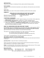
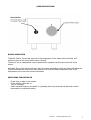
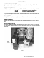
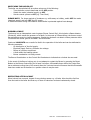
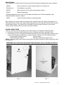
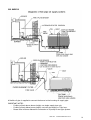
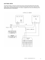
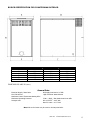
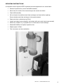
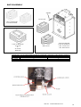
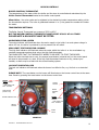
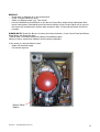
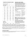
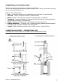
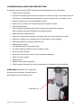
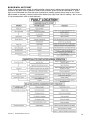
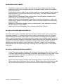
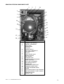
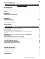
Page
2
2
INTRODUCTION/WARRANTY
- WHAT IS A CONDENSING BOILER?
AMBASSADOR (KITCHEN), COUNTRYMAN (OUTDOOR) & CONSUL (BOILERHOUSE)
CONSENSING BOILERS
USER INSTRUCTIONS
- BOILER OPERATION
- SWITCHING THE BOILER ON
- BOILER CONTROLS
- SWITCHING THE BOILER OFF / BURNER LOCKOUT / RESTARTING AFTER LOCKOUT
- RESTART
INSTALLATION
- REGULATIONS / WATER CONNECTIONS
- BOILER LOCATION
- CONNECTING OIL SUPPLY
- ELECTRICAL CONNECTION/WIRING DIAGRAM
3
3
3
4
5
6
7
8
9-10
11
TECHNICAL DATA
- BOILER SPECIFICATIONS
12-14
- SERVICING INSTRUCTIONS
15
- BAFFLE ASSEMBLY / BURNER
16
- BURNER SETTINGS
17
SENATOR (KITCHEN) & COUNTRYMAN (OUTDOOR) COMBI CONSENSING BOILERS
USER INSTRUCTIONS
- BOILER OPERATION / SWITCHING THE BOILER ON
- BOILER CONTROLS
- BUILT IN TIME SWITCH (SENATOR COMBI ONLY)
- SWITCHING THE BOILER OFF / BURNER LOCKOUT / RESTARTING AFTER LOCKOUT
- RESTART
INSTALLATION
- REGULATIONS / PROTECTION OF DOMESTIC HOT WATER / WATER CONNECTIONS
- BOILER LOCATION
- SERVICE REQUIREMENTS / THE HEARTH / CONTROL PANEL
- PREFORMED PIPEWORK / SEALED SYSTEM / PLASTIC PIPE
- CAPACITIES OF EXPANSION VESSEL / EXPANSION VESSEL SIZING / FILLING SYSTEM
- SENATOR CONVENTIONAL FLUE INSTALLATION
- CONNECTING OIL SUPPLY
- ELECTRICAL CONNECTION (SENATOR)
- ELECTRICAL CONNECTION (COUNTRYMAN)
- WIRING DIAGRAM (SENATOR & COUNTRYMAN)
TECHNICAL DATA
- BOILER SPECIFICATIONS
- COMMISSION INSTRUCTIONS
18
19
20
21
22
23
8
24
25
26
27
9-10
28
29
30
31-32
33
- SERVICING INSTRUCTIONS
33
-
34
35
36
16
FAULT FINDING COMBUSTION
FAULT FINDING COMBI
PARTS LIST
BAFFLES ASSEMBLY / BURNER
- BURNER SETTINGS
17
Issue No.1 Combined Manual 24.10.07
1
INTRODUCTION
Thank you for choosing our condensing oil boiler, please read the following carefully.
To the installer
This manual must be left with the householder by the installer who will instruct the user on the boiler
operation.
To the user
Please read the user section of this manual to familiarise yourself with the boiler operation
WARRANTY
WARRANTY FOR YOUR BOILER MUST MEET THE FOLLOWING
CONDITIONS OR YOUR WARRANTY MAY BE INVALID
Warranty on the Heat Exchanger:
Warranty on Burner and Controls:
5 Years (Excludes labour)
2 Years
CONDITIONS OF WARRANTY:
1. Boiler MUST BE installed by an OFTEC registered engineer, if not permission will be required by
building control.
2. Boiler MUST BE commissioned after installation by an OFTEC registered engineer.
3. Boiler MUST BE serviced every 12 months after installation by an OFTEC registered engineer.
4. Installer MUST COMPLETE an Installation/Commission Form, which will be found along with
your manual and this, must then be returned to the address on the warranty form. Failure to
return this form may invalidate your warranty.
WHAT IS A CONDENSING BOILER AND HOW DOES IT WORK?
On all standard boilers the flue gases that go up the chimney have quite a high temperature (200°C /
260°C) and are made up of a few different types of gases. A condensing boiler is designed so that
these flue gases pass through a stainless steel heat exchanger connected to the boiler. These flue
gases transfer heat to the water contained in the secondary heat exchanger.
This results in (a) increasing the temperature of the water returning to the main boiler
(b) Converting some of the flue gases into condensate
(c) Lowers the exit flue gas temperatures considerably (Less than 85°C)
This all results in increased efficiency in the boiler and therefore a saving on oil.
IMPORTANT CHANGES TO BOILER MANAGEMENT:
Annual Service –This is very important in order to keep the flue ways clean and ensure the boiler is
correctly set.
Quarterly Check – empty and clean the condensing trap (Fig.4)
Always ensure that the condensate is flowing freely through the outlet into the drain. This can get
dirty and block flow or it can freeze in extreme conditions.
Plume – a condensing boiler, which produces a white plume from the flue into the air. This is caused
by the low flue gas temperatures mixing with the colder air outside.
Best performance:
Radiator Heating System
Underfloor Heating System
- Flow Temperature 70°C
- Flow Temperature 50°C
- Return Temperature 50°C
- Return Temperature 40°C
Note: return temperature should never be less than 40°C
Issue No.1 Combined Manual 24.10.07
2
USER INSTRUCTIONS
Reset Button
BOILER OPERATION
The Boiler Control Thermostat responds to the temperature of the water within the boiler and
switches power to the burner when heat is required.
The burner has an independent control system which regulates the firing and (shut-off) of the
burner.
Automatic firing of the burner will occur when the water temperature within the boiler falls below the
control thermostat set point which will continue to run until the water temperature rises to the
temperature set on the boiler control thermostat.
SWITCHING THE BOILER ON
-
Check there is water in the system.
Check radiator valves are on.
Turn on oil supply.
Switch electrical supply to the boiler on (including time clock) and then set the boiler control
thermostat to recommend setting.
Issue No.1 Combined Manual 24.10.07
3
BOILER CONTROLS
BOILER CONTROL THERMOSTAT
The temperature of the water within the boiler is controlled and maintained by the Boiler Control
Thermostat located on the boiler control panel.
TEMPERATURE SETTINGS:
The Boiler Control Thermostat has a range of 50°C to 80°C. The recommended setting for the boiler
control thermostat is:
WINTER
Heating and hot water supply 80°C
SUMMER
Domestic hot water supply 65°C
It is not recommended to operate the boiler with a thermostat setting of less than 60°C as this will
precipitate corrosion, thus reducing the life of the boiler.
HIGH LIMIT STAT
The high limit lockout will occur when the water within the boiler is or has overheated e.g. reached a
temperature above that set on the high limit thermostat.
TO RESET THE BOILER
When the boiler has had time to cool, unscrew black cap and press button on the control panel to
reset.
LOCKOUT INDICATOR: RED
The lock out indicator will illuminate when the burner has failed to fire, e.g. No fuel or an electrical
fault. Wait for two minutes then press the manual reset button (coloured red – Fig 1) on the control
box to reset.
Issue No.1 Combined Manual 24.10.07
4
SWITCHING THE BOILER OFF
The boiler can be switched off at anytime using one of the following:
- Turn the boiler control thermostat to the OFF position
- Switch the mains (electrical supply) to OFF
- Set the control system to OFF (e.g. Time Clock)
PLEASE NOTE: For longer periods of shutdown e.g. while away on holiday, switch OFF the mains
(electrical supply) and turn OFF the OIL supply.
If shutdown occurs during cold weather ensure boiler is protected against frost damage.
BURNER LOCKOUT
The burner has an independent control system (Burner Control Box); this includes a flame detector
(Photocell), which senses the presence of a flame. In the event of a flame failure, the burner control
box activates a second re-ignition sequence. Should the photocell not detect a flame presence within
15 seconds the burner goes to LOCKOUT and shuts down.
Continued LOCKOUTS are a result of a fault in the operation of the boiler and can be attributed to
following examples:
- An interruption of the fuel supply.
- Electrical Supply Fault e.g. Extreme low voltage.
- Failure of a burner component.
- A fault within the heating system.
- Burner combustion not being correct.
The Burner Reset button on the Control Box illuminates to indicate that a lockout has occurred.
In the event of the Burner locking out, do not attempt to restart the Burner by pressing the Reset
Button on the Burner Control Box for at least 2 minutes. A Bi-metallic timer within the Control Box
has a minimum cooling time of 45 seconds thus the 2 minute interval will ensure that this Bi-metallic
timer has cooled and is therefore in a position where it may be reset.
RESTARTING AFTER LOCKOUT
When lockout has occurred, inspect for any obvious causes e.g. oil leaks. Also check the fuel line
from the tank to the boiler and that any oil shut off valve has not been inadvertently closed.
Issue No.1 Combined Manual 24.10.07
5
RESTART
- Check there is adequate oil in the storage tank.
- Check oil supply valves are open
- Switch on heating system (e.g. Time Clock)
- Press the Burner Reset Button on the burner Control Box, which will be illuminated. The Burner
Reset Button (illuminated)(Fig 1) will go out and the burner will commence the ignition start
sequence. After 15 seconds the Burner should fire normally.
PLEASE NOTE: Should the Burner not start, the lockout indicator, on the Control Box/Burner Reset
Button will illuminate again.
- Wait at least 3 minutes and press the Burner Reset Button again.
Failure to start a second time indicates a fault requiring attention.
In the event of a second failure to start:
- Switch off electrical supply
- Call service engineer.
Issue No.1 Combined Manual 24.10.07
6
REGULATIONS
The installation of oil-fired boilers should comply with the following standards and codes of practice:
- BS5449
Forced circulation hot water heating systems for domestic use.
- BS5410-Part 1
Oil installations up to 45kw
- BS7593
Water treatment of hot water central heating systems
- BS7671
Electrical Regulations
- Building Regulations Part 1L and J 2002 England and Wales, Part F Scottish Regulations and
Technical Booklet L Northern Ireland.
- OFTEC
Codes of Practice Published or Recommended.
After installing, the system needs to be flushed with a cleanser like Fernox Heavy Duty Restore, for
fast-acting removal of lime scale, black sludge (magnetite) and other deposits from the boiler and the
central heating system. Then add a Fernox protector to give long-term protection of the central
heating system against internal corrosion lime scale formation.
WATER CONNECTIONS
Only two connections for the heating and hot water system on a standard condensing boiler:
1. Flow from top of boiler (Fig.2) and return to top of stainless steel heat exchanger (Fig.2).
2. The PVC pipe (fig 3) is 21.5mm Ǿ and should continue from the condensate trap in side the boiler
casing, which should be plumbed to an external source ensuring one of the following options:
- Internal waste drainage system
- Soil/vent stack
- External Drainage system
- External condensate absorption point
NOTE: condensate pipe work must fall at least 50mm per metre towards the outlet ensuring all joints
are leak proof.
WARNING: the condensate trap must be filled with water prior to starting the boiler to
stop flue gases escaping
Issue No.1 Combined Manual 24.10.07
7
BOILER LOCATION
Sound levels should be discussed with the householder, as some people may be sensitive to low
noise levels in a small room, as is may appear more annoying than in larger rooms. Please Note
installation should take into account of flue position (see diagram).
RECOMMENDED FLUE POSITION
Issue No.1 Combined Manual 24.10.07
8
OIL SUPPLY
Issue No.1 Combined Manual 24.10.07
9
OIL SUPPLY
A flexible oil pipe is supplied to connect the burner to the incoming oil supply pipe.
IMPORTANT NOTES:
- If sitting oil tank above burner height, use single supply pipe only.
- If sitting oil tank below burner height, use twin pipe supply or Tiger loop.
- Please refer to Burner Manual for conversion to oil pump for two pipe system.
Issue No.1 Combined Manual 24.10.07
10
ELECTRICAL ENTRY
The electrical supply to the boiler must be wired using a double pole-isolating switch 230v/50hz,
fused 5 amps. The mains supply must be connected with the boiler dual stat, the supply will then
continue down to the burner control box. The burner is supplied with a three wire cable plug which
allows disconnection for maintenance.
Issue No.1 Combined Manual 24.10.07
11
BOILER SPECIFICATIONS FOR AMBASSADOR (KITCHEN)
DIMENSION
A
B
C
D
E
F
G
H
I
J
K
15/21 Kw
854
589
421
140
560
706
35
355
293
423
741
21/27 Kw
854
589
481
140
528
706
35
355
293
423
741
27/38 Kw
854
589
481
140
528
706
35
355
293
423
741
35/50 Kw
995
657
581
115
628
889
35
370
293
491
889
DIMENSIONS ARE IN (mm.)
Electrical Supply. 240w-50hz
Fuel: 28 Second
General Data
Oil Supply Connection ¼” BSP
High Limit Stat: Manual Reset
Maximum Control Thermostat Setting 85°C
Maximum Operating Pressure:
3 Bar – 45psi – 28m Static head room 92ft
Draught Limit
Min 12.5 Nm2 – 0.05” WG
Max 33.0 Nm2 – 0.12” WG
Issue No.1 Combined Manual 24.10.07
12
BOILER SPECIFICATION FOR COUNTRYMAN OUTDOOR
DIMENSIONS
A
B
C
D
E
F
15/21 Kw
521
868
750
894
880
485
21/27 Kw
521
868
750
894
880
485
27/38 Kw
521
868
750
894
880
485
DIMENSIONS ARE IN (mm.)
General Data
Electrical Supply. 240w-50hz
Fuel: 28 Second
Oil Supply Connection ¼” BSP
High Limit Stat: Manual Reset
Maximum Control Thermostat Setting 85°C
Maximum Operating Pressure:
3 Bar – 45psi – 28m Static head room 92ft
Draught Limit
Min 12.5 Nm2 – 0.05” WG
Max 33.0 Nm2 – 0.12” WG
Note: 28 sec fuel must only be used on Countryman boiler
Issue No.1 Combined Manual 24.10.07
13
BOILER SPECIFICATION FOR CONSUL BOILERHOUSE
DIMENSION
A
B
C
D
E
F
G
H
15/21 KW
436
402
568
385
559
694
138
352
21/27 KW
440
402
568
453
527
694
142
357
27/38 KW
440
402
568
453
527
694
142
357
DIMENSIONS ARE IN (mm.)
General Data
Electrical Supply. 240w-50hz
Fuel: 28 Second
Maximum Control Thermostat Setting 85°C
Oil Supply Connection ¼” BSP
High Limit Stat: Manual Reset
Maximum Operating Pressure:
3 Bar – 45psi – 28m Static head room 92ft
Draught Limit
Min 12.5 Nm2 – 0.05” WG
Max 33.0 Nm2 – 0.12” WG
Issue No.1 Combined Manual 24.10.07
14
SERVICING INSTRUCTIONS
A competent service engineer OFTEC registered should be appointed on an annual basis.
•
Remove inspection door, burner and baffle assembly
•
Brush down the inside of the heat exchanger and vacuum out debris
•
Clean baffle assembly
•
Pull out inserts from stainless steel heat exchanger and clean before replacing.
Ensure stainless steel heat exchanger is thoroughly cleaned.
•
Empty and clean condensing trap (Fig.4)
•
Inspect and clean burner assembly, and replace with new nozzle (see burner manual)
•
Renew any insulation e.g. inspection door or inside base of heat exchanger
•
Reassemble baffles and replace inspection door.
•
Replace paper oil filters
•
Test oil pressure and test combustion.
Issue No.1 Combined Manual 24.10.07
15
BAFFLE ASSEMBLY
INSERT
L/H STACK
2 SET OF BAFFLES
27/38 KW BOILER
1 SET OF BAFFLES
15/21 KW
&
21/27 KW
BOILERS
BOILER SIZE
15/21 KW
21/27 KW
27/38 KW
35/50 KW
R/H STACK
NO. OF INSERTS FROM L/H SIDE OF CONDENSER
10
15
21
28
35/50 KW BOILER
2 SET OF BAFFLES
8 NO. L/H STACK
7 NO. R/H STACK
REMAINING TUBES WITHOUT INSERTS
6
9
12
16
Issue No.1 Combined Manual 24.10.07
16
BURNER SETTINGS
BOILER MODEL
15/21
21/27
27/38
35/50
Btu/hr
72000
92000
130000
170000
Kw/hr
21
27
38
50
Btu/hr
63000
82000
113000
160000
Kw/hr
18.5
24
33
46
0.55 80 deg H
0.65 80 deg H
0.85 80 deg H
1.2 80 deg H
8
8
8
8
BURNER AIR SETTING
7
12
15
3.5
SMOKE
0
0
0
0
%
11.5
12
12
11
°C
80
87
87
87
MAXIMUM OUTPUT
FACTORY SETTING
NOZZLE SIZE
OIL PRESSURE
Bar
CO2
FLUE GAS
TEMPERATURE
WATER
INLET/RETURN
WATER OUTLET/FLOW
mm
22
22
22
28
mm
22
22
22
28
CONDENSATE FLOW
mm
22 pvc rigid pipe
22 pvc rigid pipe
22 pvc rigid pipe
22 pvc rigid pipe
ELECTRICAL POWER
MAX OPERATING
PRESS
BOILER EFFICIENCY*
SEDBUK A RATING
230/240 volt – 50 Hz – fused at 5 amp
Bar
2.5
2.5
2.5
2.5
%
98
99
100
99
%
93.5
93.5
94
93.2
* Please Note – Boiler Efficiency – Schedule 2 of Rules (Efficiency) Regulation 1993
Issue No.1 Combined Manual 24.10.07
17
USER INSTRUCTIONS – CONDENSING COMBI BOILERS
TIME
CLOCK
BOILER
CONTROL
THERMOSTAT
CONDENSATE
TRAP
BOILER OPERATION
The Boiler Control Thermostat responds to the temperature of the water within the boiler and
switches power to the burner when heat is required.
The burner has an independent control system which regulates the firing and (shut-off) of the
burner.
Automatic firing of the burner will occur when the water temperature within the boiler falls below the
control thermostat set point which will continue to run until the water temperature rises to the
temperature set on the boiler control thermostat.
SWITCHING THE BOILER ON
-
Check there is water in the system.
Check radiator valves are on.
Turn on oil supply.
Switch electrical supply to the boiler on (including time clock) and then set the boiler control
thermostat to recommend setting.
Ensure condensate trap is filled with water before operation
Issue No.1 Combined Manual 24.10.07
18
BOILER CONTROLS
BOILER CONTROL THERMOSTAT
The temperature of the water within the boiler and the store is controlled and maintained by the
Boiler Control Thermostat located on the boiler control panel.
Mixer Valve – the mixer valve can be adjusted to the desired hot water temperature setting, which
the householder requires. The valve is graduated between 1 to 5, the greater the number the hotter
the water.
TEMPERATURE SETTINGS:
The Boiler Control Thermostat has a range of 50°C to 80°C.
BUT THE BOILER CONTROL THERMOSTAT MUST BE SET AT 80°C AT ALL TIMES
PLEASE NOTE A ROOM STAT MUST BE FITTED
MAINS INDICATOR: GREEN
The mains indicator will illuminate when the mains supply to the boiler is on and system charge is
above 0.5 bar, the boiler is protected by a low pressure cut off switch.
HIGH LIMIT STAT INDICATOR: ORANGE
The high limit indicator will illuminate when the water within the boiler is or has overheated e.g.
reached a temperature above that set on the high limit thermostat.
THIS INDICATES THAT THE THERMOSTAT NEEDS TO BE RESET TO START THE BOILER.
When the boiler has had time to cool, the manual reset button (coloured red) on the control panel
will need to be pressed in to reset. If the high limit thermostat continues to trip, contact your
installer, as there may be a fault with the central heating system.
LOCKOUT INDICATOR: RED
The lock out indicator will illuminate when the burner has failed to fire, e.g. No fuel or an electrical
fault.
PLEASE NOTE: The reset button on the burner will illuminate on the burner control box at the same
time. Reset by pressing the reset button on the burner control box.
NEONS
GREEN - POWER
ORANGE HIGH LIMIT STAT
RED - LOCKOUT
ON/OFF
SWITCH
BOILER
CONTROL
STAT
TIME SWITCH
(Senator only)
NEONS
GREEN - POWER
ORANGE HIGH LIMIT STAT
RED - LOCKOUT
BOILER CONTROL STAT
ON/OFF
SWITCH
MIXER
VALVE
SENATOR
Issue No.1 Combined Manual 24.10.07
COUNTRYMAN
19
BUILT IN TIME SWITCH (SENATOR COMBI ONLY)
Tappets position
Out = On
Arrow
Manual switch position
1 = On (Top Position)
Clock symbol = Timed (centre position)
0 = Off (bottom position)
Tappets position
In = Off
SETTING TIME SWITCH UP
The outer dial should be set to the current time. Rotate the dial slowly in a clockwise direction, until
the correct hour is approaching the arrow marked on the dial.
MANUAL SWITCH OPERATION
The manual switch will provide On/Timed/Off Control, thereby allowing manual control of the heating
without disrupting the timed (tappet) settings.
PROGRAMME SWITCH TIMES
One tappet is equal to 15 minutes, set the number of tappets to the outer edge of the dial, equal to
the duration of time heating is required to be switched on.
Issue No.1 Combined Manual 24.10.07
20
SWITCHING THE BOILER OFF
The boiler can be switched off by turning the rocker switch, located on the underside of the control
panel, to the OFF position.
PLEASE NOTE: For longer periods of shutdown e.g. while away on holiday, switch OFF the mains
(electrical supply) and turn OFF the OIL supply.
If shutdown occurs during cold weather ensure boiler is protected against frost damage.
BURNER LOCKOUT
The burner has an independent control system (Burner Control Box); this includes a flame detector
(Photocell), which senses the presence of a flame. In the event of a flame failure, the burner control
box activates a second re-ignition sequence. Should the photocell not detect a flame presence within
15 seconds the burner goes to LOCKOUT and shuts down.
Continued LOCKOUTS are a result of a fault in the operation of the boiler and can be attributed to
following examples:
- An interruption of the fuel supply.
- Electrical Supply Fault e.g. Extreme low voltage.
- Failure of a burner component.
- A fault within the heating system.
- Burner combustion not being correct.
The Burner Reset button on the Control Box illuminates to indicate that a lockout has occurred.
In the event of the Burner locking out, do not attempt to restart the Burner by pressing the Reset
Button on the Burner Control Box for at least 2 minutes. A Bi-metallic timer within the Control Box
has a minimum cooling time of 45 seconds thus the 2 minute interval will ensure that this Bi-metallic
timer has cooled and is therefore in a position where it may be reset.
RESTARTING AFTER LOCKOUT
When lockout has occurred, inspect for any obvious causes e.g. oil leaks.
Also check the fuel line from the tank to the boiler and that any oil shut off valve has not been
inadvertently closed.
Issue No.1 Combined Manual 24.10.07
21
RESTART
- Check there is adequate oil in the storage tank.
- Check oil supply valves are open
- Switch on heating system (e.g. Time Clock)
- Press the Red Burner Reset Button on the burner Control Box, which will be illuminated. Both
burner reset button (illuminated) and the lockout indicator on the Control Panel will go out and
the burner will commence the ignition start sequence. After 15 seconds the Burner should fire
normally.
PLEASE NOTE: Should the Burner not start, the lockout indicator, on the Control Panel and Burner
Reset Button will illuminate again.
- Wait at least 3 minutes and press the Burner Reset Button again.
Failure to start a second time indicates a fault requiring attention.
In the event of a second failure to start:
- Switch off electrical supply
- Call service engineer.
Burner Reset
Button
Issue No.1 Combined Manual 24.10.07
22
REGULATIONS
The installation of oil-fired boilers should comply with the following standards and codes of practice:
- BS5449
Forced circulation hot water heating systems for domestic use.
- BS5410-Part 1
Oil installations up to 45kw
- BS7593
Water treatment of hot water central heating systems
- BS7671
Electrical Regulations
- Building Regulations Part 1L and J 2002 England and Wales, Part F Scottish Regulations and
Technical Booklet L Northern Ireland.
- OFTEC
Codes of Practice Published or Recommended.
After installing, the system it needs to be flushed with a cleanser like Fernox Heavy Duty Restore, for
fast-acting removal of lime scale, black sludge (magnetite) and other deposits from the boiler and the
central heating system. Then add a Fernox protector to give long term protection of the central
heating system against internal corrosion lime scale formation.
PROTECTION OF DOMESTIC HOT WATER
WE recommend that appropriate water softening equipment is fitted in hard water areas. Check with
local water authority if in doubt.
WATER CONNECTIONS
The following connections are required:
- Heating Flow
- Heating Return
- Overflow
- Hot Water
- Mains
- PVC Condensate Pipe
HEATING FLOW
HEATING RETURN
MAINS
OVERFLOW
HOT WATER
COUNTRYMAN OUTDOOR
MAINS
OVERFLOW
HOT WATER
HEATING
HEATING RETURN
SENATOR KITCHEN
Issue No.1 Combined Manual 24.10.07
23
INSTALLATION
SERVICE REQUIREMENTS
The boilers are serviced through an access panel at the front. A service access space of at
least 700mm should be made available at the front of the boiler.
THE HEARTH
The temperature of the surface below the boiler is less than 85°C. If the floor under the
boiler is of combustible material, then protection such as steel should be fitted between the
boiler and the floor.
Consideration should be given to the weight of the filled boiler; the floor must provide
adequate support. Please consult the building regulation for safe floor loadings.
CONTROL PANEL
The boiler control panel is factory fitted prior to despatch. The phials of the Control and High
Limit Thermostat are inserted into the pockets situated on the left hand side of the boiler
heat exchanger.
ELECTRICAL ENTRY
The electrical supply to the boiler must be 230v/50hz, fused at 5 amps. Connection of the appliance
and any system controls, to the mains supply, must be a common isolator and must be fused at 5A
maximum.
This must be fixed wired to a double pole-isolating switch that has a maximum contact separation of
2mm in both poles. The isolator should be clearly marked showing it’s purpose, and preferably
positioned close to the boiler.
Issue No.1 Combined Manual 24.10.07
24
PREFORMED PIPEWORK
-
1
1
1
1
1
of
of
of
of
of
22mm
15mm
15mm
15mm
22mm
section
section
section
section
section
labelled
labelled
labelled
labelled
labelled
Heating Flow
Mains
Hot Water
Overflow
Heating Return
Preformed pipes, on the senator Combi, can exit on the left or right hand side of the casing.
Please ensure that if flueing low level balanced flue from the side of the casing of the boiler,
that the preformed pipes are exiting on the opposite side to which the flue is exiting.
The preformed pipe on the Countryman Combi exits at the rear of the casing Base.
SEALED SYSTEM
This boiler operates on a sealed system. A pressure relief valve operating at 3 bar is fitted.
The overflow pipe must terminate in compliance with current building regulations.
The boiler is supplied with a 12-litre expansion vessel. It is the installer’s responsibility to ensure
adequate provision is made for expansion within the heating system and to install extra capacity if
required. Damage to components caused by over expansion may not be covered by warranty.
Unsuitable pipe work and fittings and factors such as sediment or residue left in the system, may
cause damage to your boiler and it’s components and may not be covered by warranty.
PLASTIC PIPE
PLEASE NOTE: When using plastic pipe on heating system, a minimum of 2 metres of copper pipe
must be used off the boiler, before connecting to plastic pipe.
PLASTIC PIPE MUST NOT IN ANY CIRCUMSTANCES BE CONNECTED DIRECTLY TO THE BOILER
Issue No.1 Combined Manual 24.10.07
25
CAPACITIES OF EXPANSION VESSELS
Safety valve setting @
3
3
3
Vessel charge and
Initial System Pressure
(BAR GUAGE)
0.5
1
1.5
LITRES
LITRES
LITRES
LITRES
5
2.1
2.7
3.9
50
4.2
5.4
7.8
75
6.3
8.2
11.7
100
8.3
10.9
15.6
125
10.4
13.6
19.5
150
12.5
16.3
175
14.6
200
EXPANSION VESSEL SIZING
Bs7074: Part1 :1989 gives full details of
accurate method of calculating the required
expansion vessel capacity, assuming that full
and accurate design information is available,
particularly total system water content.
However, in practice, it is often not possible to
calculate the system water contents with any
certainty, and therefore estimates must be
made.
The following volume approximations can be
used to give a reasonable estimate of total
system volume.
COMBI
61.5 LITRES
23.4
KW RATING
21/27
19.1
27.3
SMALL BORE PIPEWORK
16.7
21.8
31.2
1 Litre Per Kw of
System Output
225
18.7
24.5
35.1
STEEL PANEL RADIATORS
250
20.8
27.2
39.0
8 Litre Per Kw of
System Output
275
22.9
30.0
42.9
300
25.0
32.7
46.8
LOW WATER CAPACITY
RADIATORS MODERN TYPE
2 Litre Per Kw of
System Output
325
27.0
35.7
50.7
HOT WATER CYLINDER
2 Litres
350
29.1
38.1
54.6
375
31.2
40.9
58.5
400
33.3
43.6
62.4
425
35.4
46.3
66.3
450
37.5
49.0
70.2
500
41.6
54.5
78.0
Multiplying
factor for
other systems
Volumes
0.0833
Note: As an approximation, BS7074: Part1
suggests that figures of 12 litres/kw of boiler
output could be used to estimate total system
water content – this would be generous for
most systems.
EXPANSION VESSEL SIZING
0.109
0.156
Having determined the total system water
content, expansion vessel sizing can be
considered. Taking into account the other
system design factors
Full details of expansion vessel sizing and models available are given in the expansion vessel data
sheet. However, expansion vessels are supplied pre-charges at 1 bar (suitable for system static heads
up to 15 metres) and the safety valve normally pre-set at 3 bar (British Specification). For standard
conditions therefore, the above table can be used to select the required expansion vessel volume.
NB: Please note the above information (EXPANSION VESSEL SIZING) is only a guide therefore we do
not accept responsibility for sizing of systems and this does not over rule British Standards always
refer back to BS7074: Part1 if in doubt.
FILLING THE SYSTEM
Prior to filling, the system must be thoroughly flushed using a cleaning agent. The system must then
be vented of all air and recharged to maximum of 1.5 bar.
Issue No.1 Combined Manual 24.10.07
26
CONVENTIONAL FLUE INSTALLATION
The boiler is supplied as standard for use with conventional flue.
The chimney must comply with building regulations and BS 5410. Factory made insulated chimneys
are covered by BS 4543 Parts 2 & 3.
Notes on Conventional Flue:
1. Liner – A stainless steel flue liner of diameter to suit the boiler is recommended
2. Flue Pipe – can be of vitreous enamel or stainless steel
3. Bends – Bends in the flue pipe should not be greater than 135 degrees.
4. Insulation – Insulation between the flue pipe and brick chimney, is recommended to
minimize the occurrence of condensation.
5. Cowls – Cowls and pots that may restrict the flue should not be used.
6. Draught Stabilisers – Chimneys over 6 metres high may produce excessive draught
(over 4mm w.g.). Draught stabilisers may be required.
7. Length – Before bends are applied, length of flue must be at least 600mm.
COMBUSTION AIR SUPPLY – CONVENTIONAL FLUE
CONVENTIONAL FLUES MUST BE SUITABLE FOR CONDENSING BOILERS
Issue No.1 Combined Manual 24.10.07
27
ELECTRICAL CONNECTION (SENATOR KITCHEN COMBI)
The electrical supply to the boiler must be wired to a double pole - isolating switch 240v/50hz, fused
at 5 amps. A multi 3-pin plug is included with the boiler, which connects with the boiler control panel.
The burner is supplied with 4-wire cable plug, which allows disconnection for maintenance.
CONTROL OPTIONS
A Room Thermostat must be fitted for the boiler to work correctly.
A Frost Thermostat may be required this should be assessed when installing the boiler
INTEGRAL TIME CLOCK (SENATOR KITCHEN COMBI ONLY)
The integral time clock controls the heating function. The domestic hot water function is permanently
on and controlled by a heating control thermostat.
INSTALLATION OF A ROOM THERMOSTAT
Connect a room thermostat to terminal 3 and 4 on the 8 way connect strip inside the boiler control
panel and discard link wire. If neutral wire is required for room thermostat, connect neutral wire to
terminal 6 on the 8 way connect strip.
INSTALLATION OF A TIME CLOCK OR PROGRAMMABLE ROOM STAT
Connect a remote time clock or programmable room stat to 3 and 4 on the 8 way connect strip,
inside the boiler control panel and then disregard link wire.
The internal time clock can be switched to continuously on, or a link wire can be connected to 4 and
5 on the 8 way connect strip to disable integral time clock.
INSTALLATION OF FROST THERMOSTAT
Connect a frost thermostat to terminal 5 and 3 on the 8 way connect strip inside the boiler control
panel. If neutral wire is required for frost thermostat, connect to terminal 6 on the 8 way connect
strip.
Issue No.1 Combined Manual 24.10.07
28
ELECTRICAL CONNECTION (COUNTRYMAN OUTDOOR COMBI)
The electrical supply to the boiler must be wired to a double pole - isolating switch 240v/50hz, fused
at 5 amps. A multi 6-pin plug is included with the boiler, which connects with the boiler control panel.
The burner is supplied with 4-wire cable plug, which allows disconnection for maintenance.
CONTROL OPTIONS
A Room Thermostat must be fitted for the boiler to work correctly.
A Frost Thermostat may be required this should be assessed when installing the boiler
INSTALLATION OF A TIME CLOCK OR PROGRAMMABLE ROOM STAT
(COUNTRYMAN OUTDOOR COMBI ONLY)
Installation of external time clock or programmable room thermostat to Countryman Combi. The
boiler comes with a multi 6-pin plug. The electrical supply must be sent directly to the boiler, off the
fused spur and not interrupted by any forms of control i.e. time switch or programmable room
thermostat. The electrical supply to the time switch or programmable room thermostat is supplied
from the boiler. The connections to the muti pin plug are as follows:
PIN
PIN
PIN
PIN
PIN
1
2
3
4
5
=
=
=
=
=
Earth
Neutral
Live
Electrical supply out from boiler to time switch or programmable room thermostat
Switch supply back from the time switch or programmable room thermostat
The External Time Clock controls the heating function. The domestic hot water function is
permanently on and controlled by Heating Control Thermostat.
INSTALLATION OF A ROOM THERMOSTAT
Connect a room thermostat to terminal 3 and 4 on the 8 way connect strip inside the boiler control
panel and discard link wire. If neutral wire is required for room thermostat, connect neutral wire to
terminal 6 on the 8 way connect strip.
INSTALLATION OF FROST THERMOSTAT
Connect a frost thermostat to terminal 5 and 3 on the 8 way connect strip inside the boiler control
panel. If neutral wire is required for frost thermostat, connect to terminal 6 on the 8 way connect
strip.
Issue No.1 Combined Manual 24.10.07
29
WIRING DIAGRAM
SENATOR COMBI
COUNTRYMAN COMBI
Issue No.1 Combined Manual 24.10.07
30
COMBI SENATOR KITCHEN MODELS TECHNICAL SPECIFICATION
DIMENSIONS
A
B
C
D
E
F
G
H
I
J
K
L
M
N
O
15/21 KW
741
293
140
423
589
641
589
577
614
645
670
705
854
140
240
21/27 KW
741
293
140
423
589
641
589
577
614
645
670
705
854
140
240
27/38 KW
741
293
140
423
589
641
589
577
614
645
670
705
854
140
240
DIMENSIONS ARE IN (mm.)
Electrical Supply. 240w-50hz
Fuel: 28 Second
General Data
Oil Supply Connection ¼” BSP
High Limit Stat: Manual Reset
Maximum Control Thermostat Setting 85°C
Maximum Operating Pressure
Expansion Vessel Capacity 12 Litres
Spring Safety Valve @ 3 bar
Conventional Size 100-125mm
Thermostatic Mixer Valve 30°C – 70°C
Issue No.1 Combined Manual 24.10.07
31
COMBI COUNTRYMAN OUTDOOR MODELS TECHNICAL SPECIFICATION
DIMENSIONS
A
B
C
D
E
F
G
15/21 KW
645
260
681
868
684
880
827
21/27 KW
645
260
681
868
684
880
827
27/38 KW
645
260
681
868
684
880
827
DIMENSIONS ARE IN (mm)
General Data
Electrical Supply. 240w-50hz
Fuel: 28 Second
Maximum Control Thermostat Setting 85°C
Oil Supply Connection ¼” BSP
High Limit Stat: Manual Reset
Maximum Operating Pressure
Expansion Vessel Capacity 12 Litres
Spring Safety Valve @ 3 bar
Thermostatic Mixer Valve 30°C – 70°C
Issue No.1 Combined Manual 24.10.07
32
COMMISSIONING & SERVICING INSTRUCTIONS
A competent service engineer OFTEC registered should be appointed on an annual basis.
•
Isolate Power to the boiler
•
De-pressurise heating system and check expansion vessel pre-charge is the same as the cold
fill pressure, of the heating system. Expansion vessel pre-charge must not exceed 1.5 bar.
•
Remove inspection door, burner and baffle assembly
•
Brush down the inside of the heat exchanger and vacuum out debris
•
Clean baffle assembly
•
Pull out inserts from stainless steel heat exchanger and clean before replacing.
Ensure stainless steel heat exchanger is thoroughly cleaned.
•
Empty and clean condensing trap
•
Inspect and clean burner assembly, and replace with new nozzle (see burner manual)
•
Renew any insulation e.g. inspection door or inside base of heat exchanger
•
Reassemble baffles and replace inspection door.
•
Replace paper oil filters
•
Turn electrical supply to the boiler to ON.
•
Set central heating controls so they are calling for heat.
•
Set burner pump pressure.
•
Allow time for the boiler to reach normal operating temperature.
•
Check the smoke reading.
•
Measure the Co2
•
Measure net flue gas temperature.
•
Check domestic hot water flow and hot temperature is acceptable to the householder.
PLEASE NOTE: Reducing the air supply into
the burner air inlet shutter, decrease the flue
gas temperature and increases the Co2
Condensing Trap
Issue No.1 Combined Manual 24.10.07
33
BOILER WILL NOT START
Check if mains electricity supply is reaching boiler control panel, making sure control thermostat is
turned on and time clock is calling for heat. Mains indicator green should be illuminated. If green
light is not illuminated and fuse has been checked then heating system charge may be low, check
black needle on pressure, located inside boiler cabinet (top right hand side) is reading 1 bar or more.
If not depressurised, refer to fault diagnosis.
FAULT DIAGNOSIS
Issue No.1 Combined Manual 24.10.07
34
NO HEATING OR HOT WATER
-
Check there is power to the boiler, has fuse blown? If yes replace and test, if fuse
continues to blow check circulation pump is not passing heating water into circulation
pump electrical box.
Is the system pressure below 1 bar on black needle on pressure gauge? If yes recharge
system pressure by opening the filling loop valve slowly, until black needle indicator
reads (approx 1 bar)
Green neon NOT illuminated. Place rocker switch to the ON position located on the
control panel. (Check system is pressurised)
Green and orange neon illuminated. Reset start by pushing red button in, next to the
On/Off rocker switch on the control panel. Vent air from the system. Re-check system
pressure charge.
Orange neon illuminates regularly when in heating mode, check calibration of control
stat and replace if out of range.
Green and red neon illuminated, refer to Burner Locked Out (Page 5)
NO D.H.W, BUT SOME WHEN HEATING ON
Turn time switch to the off position and open hot tap. If boiler doesn’t fire up when Temp
drops approximately 1-2 minutes, remove micro switch from diverter valve, by removing
circlip located at the bottom of the switch (if micro switch is not attached to the diverter
valve, it could be damaged, this would prevent the burner and circulation pump coming on).
If not check electrical connection to switches to check that burner and circulation pump are
coming on. If not check electrical connection to switches and replace if faulty. If micro
switches are working correctly, check that cap is on plunger, If cap is not and has been
dislodged refit cap and check that plunger is moving out, when tap is open, if not replace
diaphragm.
NO D.H.W, HEATING FUNCTION CORRECTLY
-
Check 15mm pipe coming off plate heat exchanger, that goes to mixer valve is hot. If
not there could possibly be a blockage in the plate heat exchanger i.e. lime scale. If this
is the case descale if possible, or replace and check appropriate water softening
equipment has been fitted.
-
Check 15mm pipe coming off plate heat exchanger going to mixer valve is hot. But
15mm coming out of the mixer valve is not hot. Rotate mixer valve control knob in and
out, as valve may have stuck. If this does work remove, clean and replace if faulty.
Issue No.1 Combined Manual 24.10.07
35
SENATOR KITCHEN COMBI PARTS LIST
3
5
7
24
1
8
2
9
4
6
19
10
18
11
16
23
13
17
12
15
14
20
ITEM
DESCRIPTION
1
2
3
INTERNAL TIME SWITCH
CONTROL THERMOSTAT
GREEN NEON
ORANGE NEON
RED NEON
ROCKER SWITCH
HIGH LIMIT THERMOSTAT
FLOW REGULATOR
AIR VENT
SAFETY RELIEF VALVE
PRESSURE GAUGE
GATE VALVES
GRUNFOSS PUMP
DIVERTER VALVE DIAPHRAGM
MIRCO SWITCHES
PLATE HEAT EXCHANGER
LOW PRESURE SWITCH
FILLING LOOP
THERMOSTAT MIXER VALVE
EXPANSION VESSEL HOSE
12 LITRE EXPANSION VESSEL
BURNER
DOOR INSULATION KIT (NOT SHOWN)
BASE INSULATION KIT (NOT SHOWN)
CONDENSATE TRAP
SNORKEL TUBE
4
5
6
7
8
9
10
11
12
13
14
15
16
17
18
19
20
21
22
23
24
Issue No.1 Combined Manual 24.10.07
36