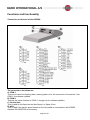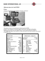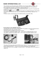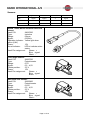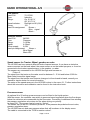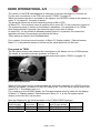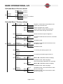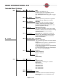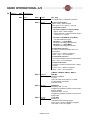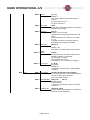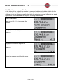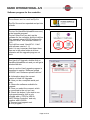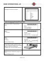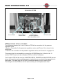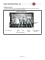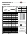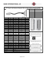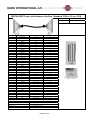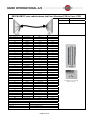
1
CONTROLLER
HC5500
Service Manual – SW 4.XX
679060-702 – Version 7.02
GB – 11.2008
www.hardi-international.com
Service Manual HC5500
Table of contents:
INTRODUCTION.................................................................................................................................................. 4
SPECIFICATIONS ............................................................................................................................................... 5
HARDI HC5500 CONTROLLER:........................................................................................................................................ 5
HC5500, SPRAY BOX AND JOBCOM POWER SUPPLY AND PROTECTION .............................................................................. 5
FUNCTIONS AND FUNCTIONALITY ................................................................................................................. 6
CONNECTORS AT THE BACK OF THE HC5500:.................................................................................................................... 6
SPRAYER CONNECTION:..................................................................................................................................................... 7
Fluid cables.................................................................................................................................................................. 7
COMMANDER: ........................................................................................................................................................... 7
NAVIGATOR: .............................................................................................................................................................. 7
NAVIGATOR or RANGER:.......................................................................................................................................... 7
Hydraulic cables .......................................................................................................................................................... 8
Commander with JobCom: .......................................................................................................................................... 8
Navigator with JobCom:.............................................................................................................................................. 8
Commander, Navigator and Ranger without JobCom:................................................................................................ 8
Master .......................................................................................................................................................................... 8
AMP CONNECTORS ........................................................................................................................................................... 9
OPTIONAL EXTRAS FOR THE HC5500 .............................................................................................................................. 10
Printer........................................................................................................................................................................ 10
Foot pedal for main ON/OFF function ...................................................................................................................... 11
SENSORS:......................................................................................................................................................................... 12
Speed sensor for Tractor: Wheel, gearbox or radar .................................................................................................. 13
Pressure sensor.......................................................................................................................................................... 13
Fan speed on TWIN ................................................................................................................................................... 14
TankGauge................................................................................................................................................................. 15
End nozzle kit ............................................................................................................................................................. 17
EXTENDED MENU FOR SW 4.00..................................................................................................................... 18
Extended Menu 1 Language....................................................................................................................................... 18
Extended Menu 2 Unit ............................................................................................................................................... 18
Extended Menu 3 Sprayer type .................................................................................................................................. 19
Extended Menu 4 Data exchange............................................................................................................................... 20
Extended Menu 5 Optional sensors............................................................................................................................ 21
Extended Menu 6 Service interval.............................................................................................................................. 22
Extended Menu 7 Factory settings............................................................................................................................. 22
Extended Menu 9 Jobcom .......................................................................................................................................... 26
TRACK SETTING IN EXTENDED MENU:........................................................................................................ 29
Menu E 8.4.1 Enable.................................................................................................................................................. 29
Menu E 8.4.2 Sensor test............................................................................................................................................ 29
Intellitrack rear sensor calibration:........................................................................................................................... 30
Menu: E 8.4.3 Chassis ............................................................................................................................................... 32
Menu: E 8.4.4 Sprayer drawbar ................................................................................................................................ 32
SafeTrack on COMMANDER .................................................................................................................................... 32
IntelliTrack on NAVIGATOR ..................................................................................................................................... 32
Menu E 8.4.5 Manual angling ................................................................................................................................... 33
Menu E 8.4.6 Boom sensor ........................................................................................................................................ 33
Menu E 8.4.7 Error print ........................................................................................................................................... 33
Menu E 8.4.8 Minimum radius................................................................................................................................... 33
Menu E 8.4.9 Half steer ............................................................................................................................................. 33
Select half steer for SPC/SPZ boom, only active with 2 boom sensors ...................................................................... 33
Menu E 8.4.10 Safety factor....................................................................................................................................... 33
Menu E 8.4.11 Boom type .......................................................................................................................................... 33
Page 2 of 87
LOOKAHEAD ................................................................................................................................................................... 34
What is the LookAhead? ............................................................................................................................................ 34
How to use the LookAhead......................................................................................................................................... 35
Calibration of LookAhead.......................................................................................................................................... 36
Pressure regulation valve for LookAhead.................................................................................................................. 36
SOFTWARE....................................................................................................................................................... 37
Software program for the controller .......................................................................................................................... 38
Communication cable ................................................................................................................................................ 40
USB to RS232 Converter............................................................................................................................................ 41
SOFTWARE UPLOAD HC5500 ........................................................................................................................ 44
SOFTWARE UPLOAD JOBCOM...................................................................................................................... 49
HANDLING THE CONFIGURATION FILE........................................................................................................ 55
Save the configuration file to the PC: ........................................................................................................................ 55
Send the configuration file to the HC5500: ............................................................................................................... 56
DUMP OF DATA FROM HC5500 CONTROLLER............................................................................................ 57
Configuration of HC5500 to dump data .................................................................................................................... 57
DUMP DATA FROM HC5500............................................................................................................................ 59
CONFIGURATION OF HYPERTERMINAL....................................................................................................... 60
HANDLING DATA FROM HYPERTERMINAL ................................................................................................. 64
LOCAL LANGUAGE MAINTENANCE.............................................................................................................. 66
How to translate a language file................................................................................................................................ 66
New software and local language .............................................................................................................................. 66
Transfer the language file from PC to HC5500......................................................................................................... 67
Download language file from HC5500 to PC:........................................................................................................... 68
PCB’S ................................................................................................................................................................ 70
PCB for Liquid........................................................................................................................................................... 70
Breakout PCB ............................................................................................................................................................ 70
PCB for section valves, 9 sections ............................................................................................................................. 71
PCB for section valves 13 sections ............................................................................................................................ 73
PCB for hydraulic ...................................................................................................................................................... 74
PCB for SafeTrack ..................................................................................................................................................... 75
PCB for Jobcom......................................................................................................................................................... 76
Resetting the Jobcom ................................................................................................................................................. 76
FAULT FINDING ON HC5500 & JOBCOM....................................................................................................... 77
LED´s on Jobcom....................................................................................................................................................... 77
Thermal fuses on the HC5500 and Spray box............................................................................................................ 78
CABLES CONFIGURATION ............................................................................................................................. 79
37–39 pole cable between Spray II and the JobCom / Breakout or 9 sec. PCB ........................................................ 79
37–39 pole cable between Hydraulic Box and the JobCom / Breakout PCB............................................................. 80
DB37M–DB37F pole cable between JobCom / Breakout PCB to 13 sec. PCB......................................................... 81
DB37M–DB37F pole cable between JobCom / Breakout PCB to 9 sec. PCB........................................................... 82
DB25M–DB25F pole HY cable.................................................................................................................................. 83
Cable for LPZ/DH...................................................................................................................................................... 84
Cable for VHZ............................................................................................................................................................ 85
15F-15F DSUB Cable................................................................................................................................................ 86
REVISION .......................................................................................................................................................... 87
Page 3 of 87
Introduction
This manual covers the HARDI Controller 5500 and the options it supports like SafeTrack
on the Commander and IntelliTrack on Navigator.
It assumes the reader has knowledge of the more basic HC2500. The menu systems,
calibration and operations of the HC5500 are built up from the HC2500. The sensors used
are also similar or the same.
This manual also at times has notes on the HC6500. This is because the HC6500 is built up
around the HC5500 and has many similarities.
Page 4 of 87
Specifications
HARDI HC5500 Controller:
Display:
1. 4th line
2. 3rd line
3. Main Readout
4. Manual
5. External rate
6. Warning
7. Boom line status
8. Register no.
Navigation keys:
9. Multi function keys
Readout presets &
Short cuts:
10. Auto On
11. Remaining Distance
or Area
12. Volume used
13. Area covered
14. Tank volume
15. Speed
16. Volume rate
HC5500, Spray box and JobCom power supply and protection
Power supply:
Operating range:
9-16V DC
Controlled processor shut down:
< 9 VDC
Protected against over voltage:
28 VDC
The electronics are protected against reverse polarisation of the power input.
Ambient temperature:
– 5°C to + 70°C
Memory:
Flash PROM non-volatile
Analog transducers typ. press. (Option 1):
Supply:
Input:
Minimum speed for volume regulation:
12 V
4 to 20 mA
0.5 km/h
Digital transducers type fan speed (option 2):
Frequency:
Trigger high:
Trigger low:
Square signal
0.5 Hz to 2 kHz
4.0 to 12.0 Volt DC
0.0 to 2.0 Volt DC
Page 5 of 87
Functions and functionality
Connectors at the back of the HC5500:
The connector’s functions are:
A: COM 1:
This can be used for dumping data, receiving data or for the connection to the printer. Use
COM 1 for software updates.
B: COM 2:
This has the same function as COM 1, though not for software updates.
C: Control box:
This is used for the liquid control box Spray I or Spray II box.
D: AUX:
This is used if the tractor speed sensor or the foot pedal is connected to the HC5500.
Harness P/N 28027600 is necessary.
Page 6 of 87
Sprayer connection:
Fluid cables
Cables details can be found in the cables configuration chapter.
COMMANDER:
1. HC2500/5500
2. Spray II
3. Hydraulic Box
4. Cable:
26004200 L=17,5m
28028700 L=14m
28027500 L=11,5m
28028900 L=8m
28028800 L=5m
26003900 L=2m
26028300 L = 0,5m
5. JobCom or Breakout PCB
6. Cable P/N 26004900
7. 13 sec PCB P/N 26004800
NAVIGATOR:
1. HC5500
2. Spray II
3. Hydraulic Box
4. Cable P/N: 26004200 L = 17,5m
28028700 L=14m
28027500 L=11,5m
28028900 L=8m
28028800 L=5m
26003900 L=2m
26028300 L = 0,5m
5. JobCom
6. Cable P/N 26023800
7. 9 sec PCB P/N 72173900
NAVIGATOR or RANGER:
1. HC2500/5500
2. Spray II
3. Hydraulic Box
4. Cable:
26004200 L = 17,5m
28028700 L=14m
28027500 L=11,5m
28028900 L=8m
28028800 L=5m
26003900 L=2m
26028300 L = 0,5m
7. 9 sec PCB P/N 72173900
Page 7 of 87
Hydraulic cables
Cables details can be found in the cables configuration chapter.
Commander with JobCom:
1. HC5500
2. Spray II Box
3. Hydraulic Box
4. Cable P/N: 72236600, L=5m
72236400, L=8m
5. JobCom with DAH Interface
6. Cable P/N 26016900
7. Hydraulic junction box
9. SafeTrack and lock cable P/N26024000
Navigator with JobCom:
1. HC5500
2. Spray II Box
3. Hydraulic Box
4. Cable P/N: 72236600, L=5m
72236400, L=8m
5. JobCom DAH Interface
6. Cable P/N 26016900
7. Hydraulic junction box
10. IntelliTrack cable P/N26024100
Commander, Navigator and Ranger without JobCom:
1. HC5500
2. Spray II Box
3. Hydraulic Box
4. Cable P/N: 26008400, L=8m
6. Cable P/N 26016900
7. Hydraulic junction box
11. Breakout PCB
Master
1. HC5500
2. Spray II Box
3. Hydraulic Box
4. Cable P/N: 72168100, L=8m
72278300, L=12m
7. Hydraulic junction box
Page 8 of 87
AMP connectors
The AMP connectors have each of the legs numbered so they are easy to identify. The
table shows how the wires are mounted in the plug and what function the wires have.
AMP plug
Pin & Wire connection
AMP Super Seal
Function
Colour
2
+
Brown
3
Signal
Blue
1
-
Black
Page 9 of 87
Optional extras for the HC5500
Printer
A printer can be fitted for the HC5500, as shown on Picture 1.
Printer
Picture 1: Printer for the HC5500
The printer can print out several kinds of data from the HC5500.
Picture 2 is an example of a printed register and Picture 3 a printed configuration.
Register printout gives the user sprayed area, volume rate that has been used etc.
The configuration print is very useful for a quick overview of how the controller is set up and
for spotting errors.
Picture 2: Print of the register
Picture 3: Print of the configuration
Page 10 of 87
The connection from the printer to the HC5500 is done through COM 1 or COM 2. The
printer is powered through the COM port so there is only one plug for the connection.
The configuration of the com port is done in Extended Menu 4.
In menu E4.1.1 Equipment type, Printer must be chosen and in menu E4.1.2 the baud rate
must be set to 9600.
In the section "Configuration of HC5500 to dump data” is a detailed description of the setup.
If the printer does not work, then check the connection to the COM port and see if it is
correct.
If it does not print, check the paper is threaded correctly (not reverse side).
Foot pedal for main ON/OFF function
The foot pedal is an extra option for the HC5500. The pedal is connected through the wire
harness that can be seen on Picture 4 and
Picture 5.
The wire harness is plugged into the AUX connector.
The “Speed2” connector has GND on pin1, +12V on pin 2 and Speed signal on pin 3.
The “Switch” connector has GND on pin 1, +12V on pin 2 and Switch signal on pin 3.
Picture 4: Foot pedal for the HC5500
Picture 5: Wire harness for the HC5500
The setup of the foot pedal to the HC5500 is done in E8.5.1. The menu tree can be seen in
section “Extended Menu 8”. There are two choices depending on the switch type.
The HC5500 can be set to a toggle or a pulse function. The standard HARDI foot pedal is a
toggle type.
Page 11 of 87
Sensors:
Angle sensor
Sensor
AMP Con
PCB
Blue
Signal
Signal
3
Signal
Black
GND
GND
1
-
Brown
+12V
+12V
2
+
Speed, TWIN, Boom and SafeTrack lock
sensor
Hardi P/N
28047500
Type:
Inductive
Range:
0-8mm
Signal:
0-200Hz
Operation indicator: Yellow light when
active (0,8V)
Power:
12V
Visual indicator:
LED to indicate active
status
Hardi Pin assignment:
Brown +
Blue signal
Black Front angle sensor:
Hardi P/N
26005700
Type:
Potentiometer
Range:
0-70°
Signal:
0,5 - 4,5V
Centre position:
2,5 V
Power:
12V
Hardi Pin assignment:
Brown +
Blue signal
Black SafeTrack rear sensor:
Hardi P/N
26005800
Type:
Potentiometer
Range:
0-120°
Signal:
0,5 - 4,5V
Centre position:
2,5 V
Power:
12V
Hardi Pin assignment:
Brown +
Blue signal
Black -
Page 12 of 87
Flow sensor:
Hardi P/N
Type:
Range:
72117500
Inductive
On, 0,2-0,5 V
Off, 6,5-7,0 V
Visual indicator:
Red light at Off (0,8V)
Power:
12V
Hardi Pin assignment:
Brown +
Blue signal
Black Pressure sensor:
Hardi P/N
842022
Type:
Pressure
Range:
0-10 Bar
Signal:
4-20mA
Power supply:
8-30V
Hardi pin assignment:
Brown +
Blue Signal
Black N/C
Speed sensor for Tractor: Wheel, gearbox or radar
The HC5500 can have several different kinds of speed sensors. It can have an inductive
sensor mounted on the back wheel, the same sensor as on the trailed sprayers, or it can be
connected to the tractors speed sensor, in the gearbox, or radar.
The sensors are connected to the HC5500 through wire harness on
Picture 5.
The signal from the tractor or the radar must be between 0 - 5 Volt and below 2,000 Hz.
Most radar’s have this signal range.
The signal from the tractors can however change a lot from brand to brand; consult your
manual or tractor dealer for more information.
The setup of the speed sensors in the HC5500 is done in the menu 3.1. Further instructions
about the connection and calibration can be found in the instruction book.
Pressure sensor
An optional 4 to 20 mAmp pressure sensor can be fitted to the liquid system.
With the sensor, the controller can switch to pressure based regulation when the flow drops
below the minimum rate measurable by the flow meter. Preventing LookAhead from winding
the pressure regulation valve down too far when driving very slowly.
In menu E8.1.7 the sensor has to be set to “Active”.
The sensor can be set for a minimum pressure. If the pressure drops below the set value,
pressure regulation stops.
The HC5500 has min and max pressure alarm that will be shown in the display menu.
The cable is connected to the “PCB for section valves”.
Page 13 of 87
The version of the PCB used depends of what type of sprayer the sensor in mounted on.
For the wire connections to the PCB, see section “PCB’s” on pages 70.
When the pressure sensor is mounted on the sprayer, the HC5500 is setup to the sensor. In
menu “5” on pages 21, the setup is shown.
The pressure sensor has a fixed measuring range in Bar or PSI.
In Menu E5.1.1 the minimum value is typed in and in menu E5.1.2 the maximum is typed in.
The measuring range is written on the pressure transducer. Our standard is 0 to 10 Bar.
Note that the sensor is ignored if the minimum input is less than 3 mAmp.
In menu E8.1.3 is the minimum allowed pressure typed in. In practice, this means the
regulation will stop if the pressure goes below this value.
These setting are done in the Extended Menu.
For a readout, the sensor must be setup. In Menu 2.1 Display readout / Optional sensor
Menu 2.1.3, the pressure sensor is chosen so the actual pressure can be seen.
Fan speed on TWIN
The Fan speed sensor can measure the revolutions on the blower unit on a TWIN sprayer.
The sensor is mounted on blower as shown in Picture 6.
For connecting the wiring from the Fan speed sensor see section “PCB’s” on pages 70.
Picture 6 Fan speed sensor
When the Fan speed sensor is mounted and the wires are connected, the HC5500 must be
setup for the sensor. In menu E5.2 the PPU value is set. The PPU value can be seen in the
menu E5.2.1. The default value is 1.
For a reading on the HC5500 display, the Fan speed sensor must be setup for the display.
In Menu 2.1, Display readout / Optional sensor, Menu 2.1.3, is the Fan speed sensor
chosen so the fan r/min can be seen.
Note the following for the Linak actuators on the TWIN FORCE sprayers
Spray II box &
AMP
Linak
Voltage
Signal
Linak actuator
connector Part no.
(min to max stroke)
Breakout PCB
4 pin
262034
1.0 to 5.0 V
Analogue
JobCom PCB
4 pin
262034
1.0 to 12.0 V
PWM (Hz)
Page 14 of 87
TankGauge
The TankGauge (digital contents sensor) is a sensor that can measure how much liquid is in
the tank. It has no automatic function. It can give a warning when the tank is about to run
dry.
Connecting TankGauge
Wire between JobCom and 26007300
AMP Super Seal
2
3
1
PCB
+
Sig
-
Wire
Brown
Blue
Black
Wire (old version)
Green
White
Brown
Figure 1 Wire for connection between JobCom and TankGauge
The cable is fitted with an AMP plug and three lose wires at the other end. It is attached to
the JobCom at J1, “Tank gauge”.
For JobCom with hardware version before 2.0, a 10Kohm resistor is fitted between
connector 2 & 3 on the JobCom.
Figure 2 shows the resistor location.
Black
wire
Signal
Blue
wire
+
Brown
wire
Figure 2 Mounting of the 10 K ohm resistance in the JobCom
Distribution Valves Junction Box
Models without JobCom:
A. TankGauge is mounted on PCB in
distribution valves junction box.
Green/Grey wire is connected to the
blue wire from TankGauge.
B. Is mounted in OPT 1 as shown.
Brown wire +
Black wire
–
If a speed sensor is present, connect
it in parallel.
A
B
The cable from the Spray box has two lose wires which are not connected in the JobCom.
These much be attached to the plug as shown on Picture 7
Page 15 of 87
Left side = Green/Gray
Right side = Pink/Yellow
Picture 7 Connection of the two wires from Spray box cable
The sensor is mounted on the back side of the sump of the tank.
Settings in the HC5500
“Extended Menu 5 Optional sensors" is the setup menu. In Menu E5.3.1 chose “HARDI”.
To check the connections, the frequency with an empty tank can be checked.
Menu 4.5.3.3, Tank Gauge, should read be between 100 and 200 Hz.
How does it work?
The TankGauge sensor measures the pressure created by the water in the tank. The
sensor sets data points for each 25 mm of water level. 100 data points are available. The
data points are registration marks where the tank sensor registers the pressure and
therefore how much water there is left in the tank at this water level.
The data points can be seen in Menu E8.2.3. They can also be edited in this Menu.
For setting the data points, the flow sensor must first be calibrated.
Next step is to fill the tank completely with a known quantity of water.
When the calibration starts, the flow sensor will register how much water is sprayed out and
the tank sensor will register the pressure for every 25 mm water level until the tank is empty.
At the end of the calibration, the actual verses the theoretical quantity of water is set just like
doing a “Tank Method” calibration of the nozzles. This will fine tune the flow sensor PPU.
The calibration of the TankGauge is described in the instruction book.
When the TankGauge is used in use, there are two modes:
• When the sprayer is moving
• When the sprayer is stationary
When the sprayer is moving, the HC5500 will calculate an average value of the read out
from the TankGauge. The average value is necessary because of the movement of the
liquid in the tank will when the sprayer is moving. If a not averaged value was shown, the
readout would be useless for the driver.
When stationary, the value is not averaged. The movement of the liquid in the tank should
stop and the average value is therefore not necessary.
Page 16 of 87
End nozzle kit
The End nozzle kit is connected to the “PCB for section valves”, seen on page 71. For
accurate boom width whilst using the end nozzles, Menu 3.3.4 needs to be set up. For more
information, see in the instruction book for the HC5500.
Picture 8 End Nozzle kit
Page 17 of 87
Extended Menu for SW 4.XX
To access Extended Menu, press and hold the “ESC” button, switch the power ON and wait
until the menu is opened.
The “[xxx]” indicates the choices or range.
The factory default and helpful notes like increments of change are in italics.
Extended Menu 1 Language: Here the is language choice. There are standard languages
and place for two local languages that can be uploaded to the HC5500 by a service person.
Note: For Russian, the HC5500 hardware version with Cyrillic text is used.
Extended Menu 2 Unit: Is for what unit the controller shall use.
Extended Menu 3 Sprayer type: The basis setup of what kind of sprayer is the HC5500
attached to and what kind of liquid system is mounted on the sprayer.
Extended Menu 4 Data exchange: Setup of the data communication.
HC5500 can be attached to other units like a PC, printers, variable Rate Application or
remote control. The communication between the HC5500 and the unit has to be set up
correctly.
The setup and use of the com ports are described in the “Software” section of this manual.
Extended Menu 5 Optional sensors: Setup of optional sensors that can be fitted. It is
typically the pressure, fan revolutions and tank contents (TankGauge).
Extended Menu 6 Service interval: Setup of the service interval.
Extended Menu 7 Factory settings: Setup of factory settings
Extended Menu 8 Settings: Settings of the regulation, tank, track and misc. settings are
done.
Extended Menu 9 JobCom: Is for setup of the JobCom, TWIN actuators and read out of
the software version and serial number.
Extended Menu 1 Language
E1 Language [UK, D, DK, F, SF, HU, Local 1, Local 2]
Default is UK.
Local 1 & 2 are languages that can be added with a PC and the “HC 5500 Language config”
software or another HC5500.
Extended Menu 2 Unit
E2 Unit
[Metric, US]
Page 18 of 87
Extended Menu 3 Sprayer type
E3.1 Field sprayer
E3.1.1 Liquid system
[Equalization, Not equalization, Circulation]
Default is Equalization.
Equalization = System with liquid return to tank from
section valves; e.g. EVC.
Not equalization = System without returns to tank;
e.g. EFC on CM05.
Circulation = System where liquid constantly
circulates in the boom lines.
E3.1.2 Dual Line
E3.1.2.1 System type
[Not present, 2 stage, 3 stage]
Default is Not present.
2-stage: Line A will always be open, and Line B can
be switched on and off automatically.
3-stage: Line A switches to B, then Line A comes on
so both A & B are on.
Sprayer
E3 type
E3.1.2.2 Sensor type
[Pressure, Speed]
If a pressure transducer is fitted, pressure is used to
trigger the line change.
E3.1.2.3 System lag
[Second]
Default is 1.0 sec.
System lag prevents oscillation when spray lines
change.
E3.1.2.4 Line overlap
[Second]
Default is 1.5 sec.
System overlap allows the activated spray line to
stabilise before the other line is turned off.
E3.2 Mistblower
E3.2.1 Liquid system
[Equalization, Not equalization, Circulation]
Default is Equalization.
Equalization = System with liquid return to tank from
section valves; e.g. EVC.
Not equalization = System without returns to tank;
e.g. Solenoid controls.
Circulation = System where liquid constantly
circulates in the boom lines
E3.2.2 Sub unit
[Standard, UCR]
Default = Standard (UCR affects menu 3.3)
UCR = Unit Canopy Row. Bases application on the
size of the tree canopy.
Page 19 of 87
Extended Menu 4 Data exchange
COM 1
E4.1 setup
E4.1.1 Equipment type
[Printer, Dump, Printer & dump, GSM,
VRA/remote]
Dump is for data transfer to a PC via for
example Microsoft HyperTerminal.
GSM is not used.
Variable Rate Application/remote is signal from
an external source.
Data
E4 exchange
E4.1.2 Baud rate
[19200, 9600, 4800, 2400, 1200]
Default is 9600.
Use 9600 for HARDI 12 volt printer.
E4.1.3 Protocol select
[HARDI VRA proto.]
Only one protocol available at the moment.
COM 2
E4.2 setup
E4.2.1 Equipment type
[Printer, Dump, Printer & dump, GSM,
VRA/remote]
Dump is for data transfer to a PC via for
example Microsoft HyperTerminal.
GSM is not used.
Variable Rate Application/remote is signal from
an external source.
E4.2.2 Baud rate
[19200, 9600, 4800, 2400, 1200]
Default is 9600.
Use 9600 for HARDI 12 volt printer.
E4.2.3 Protocol select
[HARDI VRA proto.]
Only one protocol available at the moment.
Page 20 of 87
Extended Menu 5 Optional sensors
E5.1 Pressure
Connected
to section
valve PCB.
E5.1.1 Minimum
[-9.9 to 9.9]
Default is 0.0 Bar
4 -20 mAmp sensor.
See sensor for minimum value.
See “Pressure sensor” section.
E5.1.2 Maximum
[0 to 99.9]
Default is 10.0 Bar
See sensor specifications for maximum value.
Optional
E5 sensor
E5.2 Fan speed
Connected
to section
valve PCB.
E5.2.1 PPU
E5.3 TankGauge
For sprayers
with
Breakout
PCB or
JobCom.
E5.3.1 Sensor Type
[0 to 99.99 PPU]
Default is 1
Digital input.
One pulse per revolution = 1.00 PPU.
See “Fan speed” on TWIN section
[Not present, Fillmeter, ME Tank Control,
Hardi]
For Hardi TankGauge, choose Hardi.
E5.3.2
PPU
[0.000 to 999.999 PPU ]
Connect to Breakout PCB or JobCom.
See “TankGauge” section.
Hardi has the TankGauge 0-250mbar pressure
transducer fitted to sump.
E5.X Sensor x
Only with
Breakout
PCB or
JobCom
Unit
Default
PPU
1
E5.5.1
min
0
E5.5.2
max
359
E5.6.1
min
-20
E5.6.2
max
70
E5.7.1
min
0
E5.7.2
max
100
E5.8 RPM sensor
PPU
1
E5.9 Extra 1
PPU
1
E5.10 Extra 2
PPU
1
E5.11.1
min
0
E5.11.2
max
5
E5.12.1
min
0
E5.12.2
max
5
E5.4 Wind speed
Wind
E5.5 direction
Air
E5.6 temperature
Relative
E5.7 humid
E5.11 Extra 3
E5.12 Extra 4
Page 21 of 87
Extended Menu 6 Service interval
Service
E6 interval
PIN = 04711
E6.1 A hours
10 hours.
E6.2 B hours
50 hours.
E6.3 C hours
250 hours.
E6.4 D hours
Hours are not defined.
E6.5 Nozzle
50 hours.
Extended Menu 7 Factory settings
E7.1 Total register
E7.1.1
Register 0. Shows start & stop dates & time.
E7.1.2
Shows total volume & area.
E7.1.3
Shows average & max. speed.
E7.1.4
Shows distance travelled & spraying time.
E7.1.5
Show work rate & average volume rate.
E7.2 Master reset
PIN = 12345
Send
E7.3 configuration
Factory
E7 settings
Receive
E7.4 configuration
Resets all values except for Register 0.
Config
E7.3.1 only
With
E7.3.2 language
Readable text file that can be sent to a HC 5500
or a PC.
Config
E7.4.1 only
With
E7.4.2 languages
Readable text file that can be received from a
HC 5500 or a PC.
Readable text file
Readable text file
Send
E7.5 program
For sending HC 5500 program to PC
Receive
E7.6 program
For receiving HC 5500 program from PC
Send
E7.7 Language
Box to
E7.7.1 box
[UK, D, DK, F, SF, HU, Local 1, Local 2]
Readable text file. Select language.
Use communication cable Ref. No. 72271600.
Box to
E7.7.2 PC
[UK, D, DK, F, SF, HU, Local 1, Local 2]
Readable text file. Select language.
Receive
E7.8 Language
Box to
E7.8.1 box
PC to
E7.8.2 box
Readable text file. Use communication cable
Ref. No. 72271600.
Readable text file. Use communication cable
Ref. No. 72271600.
Page 22 of 87
Extended Menu 8 Settings
E8.1 Regulation
E8 Settings
E8.1.1 Min. duty cycle
[2%]
Minimum and default is 2%.
Increase value if motor hesitates to turn.
For LookAhead, set to 5% +/- 1%.
See “Description 2 Min. duty cycle” on page
28
E8.1.2 Min. speed
[0.5 km/h]
Minimum speed required before regulation
valve will operate. Default is 0.5 km/h.
E8.1.3 Min. pressure
[0.0 Bar]
Default is 0.0 Bar. At 0.0 Bar, feature is
disabled. Pressure transducer needed.
If pressure drops below the set value, the
pressure regulation will stop.
E8.1.4 Valve test
[Start test? Yes, No]
This tests the regulation valve with position
feedback. Valve must not be at max. setting.
Valve will increase 2 turns and then
decrease 2 turns.
E8.1.5 Look Ahead
[Yes, No] See “LookAhead” on page 34
Default = No. Regulation valve must have
position feedback transducer and Boom
sensor must be fitted.
E8.1.6 Regulation delay
[0 to 9 sec]
Default = 3 seconds.
This is time the regulation valve waits before
starting.
Delay allows fluid system to stabilise before
regulation valve starts operation.
For few boom sections and or big liquid flow,
3 s is recommended.
For many boom sections and or small liquid
flow, 1 or 2 s is recommended.
E8.1.7 Sensor E.8.1.7.1 Pressure
[Active, Passive]
Default = Passive
E.8.1.7.2 Rpm
[Future use]
E8.2 Tank
E8.2.1 Tank size
[L]
Default is 1000
Value set if a TankGauge is not fitted.
Maximum fill:
CM 3200=3500
CM 4400=4900
CM 6600=7000
NAV 3000=3300
NAV 4000=4400
E8.2.2 (Future use)
E8.2.3 Data points
Page 23 of 87
[0000]
Calibration values for HARDI TankGauge.
Can be edited by use of Navigation and
Enter keys.
E8 Settings
E8.3 (Future use)
E8.4 Track
E8.4.1 Enable
[No, Yes]
To enable Safe- or IntelliTrack function.
E8.4.2 Sensor
test
E8.4.2.1 Front sensor
Approx. 2.50 V when straight.
Alarm given if < 0.2 Volt or > 4.8 Volt.
E8.4.2.2 Rear sensor
E8.4.2.2.1 Readout in deg and Volts
Approx. 2.50 V when straight
If DAH interface is used, an alarm given if
< 0.5 Volt or > 4.5 Volt.
E8.4.2.2.2 CALIBRATE (Only NAV)
Turn the drawbar full right
E8.4.2.2.3 - - > (Only NAV)
Readout and setting right extreme
E8.4.2.2.4 < - - (Only NAV)
Readout and setting left extreme
E8.4.2.3 Boom sensor 1
For CM: 0.8 V when unfolded and 5.0 V
when folded.
For NAV: 0.0 V. Sensor is optional.
Values < 0.5 V = not connected
E8.4.2.4 Boom sensor 2
0.8 V when unfolded and 5.0 V when folded.
Value < 0.5 V = not connected.
E8.4.2.5 Lock sensor
For CM: 0.8 V when locked and 5.0 V when
unlocked.
For NAV: 0.0 V. Sensor is optional.
Values < 0.5 V = not connected
E8.4.3 Chassis
[CM05 S, CM05 M, CM05 L, NAV S,
NAV M]
Default is CM05 M
For CM:
Use S for 3200, M for 4400, L for 6600.
For NAV3000L and 4000L:
Use NAV 07 M.
E8.4.4 Sprayer
drawbar
[0-200cm]
Default for CM: 101 cm
Length from drawbar pin hole to front anchor
bolt for drawbar.
Default for NAV: 100 cm
Length from drawbar pin hole to rear bolt on
pump base.
E8.4.5 Manual
angling
[- 9 to 9% ]
Default is 0.
Sets the manual steering speed.
Note + and - can be changed by toggling.
Use steps of 10% as a guide.
Page 24 of 87
E8.4.6 Boom
sensors
[0, 1, 2]
Default: 1.
This is the number of boom fold sensors
present.
For CM: Choose 1 or 2
For NAV: Choose 0
E8.4.7 Error print
[Yes]
Prints last 3 hazardous situations and shows
Alteration log changes.
E8.4.8 Minimum
radius
[6.0 m]
Default = 6.0 m for NAV.
CM Minimum turning radius allowed for the
trailer.
Tank size 3200 L= 6.5, 4400 L= 7.0, 6600
L= 9.0.
Increase to achieve a soft-stop (prevent
bottoming out) on trapeze cylinders.
E8.4.9 Half steer
[No,Yes]
Default = No
SPC/SPZ, only active with 2 boom sensors
Safety
E8.4.10 factor
E8.4.11 Boom type
E8.5 Misc.
E8.5.1 Foot switch
[100%]
Raising this value increases captiousness.
Default is 100% for a CM 4400.
For CM 3200, use 90%
For CM 6600, use 120%.
Use steps of 10% as a guide to changes.
[L, M, H]
Not active
Default: M
Classification of boom type. Light, Medium
or Heavy.
[Disable, On/off level, On/off pulse]
For remote ON/OFF of main switch, it allows
the use of other switch systems.
See “Foot pedal” section.
E8.5.2 Rate deviation [Step size:
XX %]
Default is 10%.
Can be altered.
If set at 0%, this allows 3 rates to be set up
in menu 1.1.
E8.5.3 Capacity left
Page 25 of 87
[Distance, Area]
Affects readout from Display icon. Will show
distance or area remaining.
Extended Menu 9 JobCom
E9.1 Enable
[Yes, No]
Must be enabled for use with Track or
AutoSectionControl.
E9.2 Communication
[ID x; ACK: x NACK: x; Timeout x]
ACK=acknowledged message, NACK= not
acknowledged.
ID= identification where "0" is JobCom, Timeout=No
answer from JobCom.
E9.3 ComLog
9 latest
communication
errors
Date and time for error, ID of hardware with fault, M =
E9.3.1 Message No., E = Error.
E9.3.X As above
E9.3.9 As above
E9.4 Input test
Shows actual
sensor reading.
E9 JobCom
E9.4.1 Frequency
E9.4.2 Switch
Page 26 of 87
E9.4.1.1
Speed
Hz
E9.4.1.2
Flow1
Hz
E9.4.1.3
Flow2
Hz
E9.4.1.4
Flow3
Hz
E9.4.1.5
TankGauge
Hz
E9.4.1.6
Wind speed
Hz
E9.4.1.7
Fan speed
Hz
E9.4.1.8
RPM sensor
Hz
E9.4.1.9
Extra 1
Hz
E9.4.1.10 Extra 2
Hz
E9.4.2.1
Pendulum lock
hi/lo
E9.4.2.2
Ladder up
hi/lo
E9.4.2.3
(Future use)
E9.4.2.4
Filter S
hi/lo
E9.4.2.5
Filter P
hi/lo
E9.4.3 Analogue
E9.5 Reset JobCom
E9.4.3.1
Slant
Volt
E9.4.3.2
Boom height
Volt
E9.4.3.3
Tilt L
Volt
E9.4.3.4
Tilt R
Volt
E9.4.3.5
Foam blob dist
Volt
E9.4.3.6
Twin angle
Volt
E9.4.3.7
Twin fan speed
Volt
E9.4.3.8
Distance L
Volt
E9.4.3.9
Distance R
Volt
E9.4.3.10 Distance centre
Volt
E9.4.3.11 Extra 3
Volt
E9.4.3.12 Extra 4
Volt
E9.4.3.13 Air temperature
Volt
E9.4.3.14 Relative humid
Volt
E9.4.3.15 Wind direction
SmartValve1
E9.4.3.16 setpoint
SmartValve2
E9.4.3.17 setpoint
Volt
Volt
Volt
Reset of JobCom
PIN = 74650
E9.6 TWIN actuators
E9.6.1 Fan speed
[Fwd. Rev]
To reverse present setup for actuator.
E9.6.2 Air angle
E9.7 Serial number
[Fwd. Rev]
To reverse present setup for actuator.
Shows software version and serial number
Page 27 of 87
Description 1 EVC compared to EFC
The difference between the EVC and the EFC section valve is that the EFC section valve
has no pressure equalisation. The equalisation is adjusted by the pressure regulation valve
and is controlled by the computer.
Picture 9 shows the EVC section valve, the circled being the equalisation valve. This is the
clearest difference between the EVC and the EFC when looking at the section valves.
Picture 10 shows the EFC. Here there are no equalisation adjustment valves.
Picture 9 EVC with the equalization system
Picture 10 EFC without the equalization
Description 2 Min. duty cycle (or PWM, Pulse Width Modulation)
Figure 3 Pressure regulation valve
Figure 4 Duty circle for the pressure regulation
Menu: E 8.1.2
Minimum duty cycle (or PWM) is for adjusting the speed of the pressure regulation valve.
When the valve is trying to find the right flow, the speed of the valve must not be too high or
to low. If the speed is too high, the valve will be unsteady – if the speed is too low, the valve
not move as it can not overcome the friction.
Adjustment of the valve can therefore be as follows; find out where the valve is unsteady
and then reduce the min. duty cycle a bit.
The best setting for duty cycle is shown on Figure 4 in the circle. It shows the duty circle as
the setting should be. The flow, bottom line, is stable and the duty circle is circling around
the flow setting until it finds the right position.
Page 28 of 87
Track setting in Extended Menu:
The configuration of the sprayer is saved in the controller; these setting should only be set
again after a master reset of the controller.
Menu E 8.4.1 Enable
Tracking can be either enabled/disabled in this Menu. If tracking is set to disabled, it will trail
as a normal trailer.
Menu E 8.4.2 Sensor test
Front sensor adjustment:
COMMANDOR and NAVIGATOR
E8.4.2.1 Front sensor
Adjust front potentiometer to 2.50 V when
straight.
Alarm given if < 0.2 Volt or > 4.8 Volt.
Only NAVIGATOR
Use the protractor, ref. no. 72547300 to
adjust the drawbar angle to 0 degrees
COMMANDOR and NAVIGATOR
Enter menu:
E8.4.2.2.1 Rear sensor
Adjust rear potentiometer to 2.50 V when
straight.
Alarm given if < 0.2 Volt or > 4.8 Volt
Page 29 of 87
IntelliTrack rear sensor calibration:
At the factory of the angle of the drawbar is measured and there should be a label with the
angel inside the JobCom lid of the sprayer. If you find the label with the angel it is not
necessary to do the following measurement with the protractor, you can just put in the angle.
If you do not find the label with the angel do following measurement:
E8.4.2.2.2 CALIBRATE
Open menu E.8.4.2.2.2 to program the
controller
Turn the drawbar to full right
E8.4.2.2.2.1
Program the measured angle in the
controller
E8.4.2.2.2.2
This is the measure result for right angle.
Page 30 of 87
Use the protractor, (72547300), to measure
the maximum right angle
Key in values in E.8.4.2.2.2.3 as shown.
S: Value from rear sensor.
C: This is the actual physically measured
value with the protractor.
Use the arrow keys to chance the value,
finish with ENTER, and continue with the
calibration.
E8.4.2.2.3 - - >
Readout and setting right extreme
Do the same for the left angle in menu
E8.4.2.2.4 < - -
Note the measured values inside the
JobCom lid.
In case of master reset the calibrations
procedure must be done again.
H=right
L=left
Page 31 of 87
Menu: E 8.4.3 Chassis
The correct chassis with tank size must be set. Choices are:
COMMANDER Setting
NAVIGATOR
CM05 S
3000 L
3200 L
CM05 M
4000 L
4400 L
CM05 L
6000 L
Setting
NAV 07 S
NAV 07 M
If the HC5500 is not set up to the correct chassis, the system will not be accurate.
Menu: E 8.4.4 Sprayer drawbar
SafeTrack on COMMANDER
Sprayer drawbar length is measured from
the drawbar pin hole to the middle of the
first bolt that holds the drawbar on the
sprayer. See Figure 5
Figure 5 Sprayer drawbar for CM
IntelliTrack on NAVIGATOR
Sprayer drawbar length is measured from
the drawbar pin hole to rear bolt on pump
base.
Page 32 of 87
Menu E 8.4.5 Manual angling
The manual angling speed is how fast the
sprayer will turn when the sprayer is
manoeuvred manually. Switch 11 is used
when the sprayer is manoeuvred manually.
See Picture 11.
Picture 11 Hydraulic control box with track
Menu E 8.4.6 Boom sensor
The sensor detect whether the boom is folded or unfolded.
For CM, boom sensor is normally set to one.
For SPC and Eagle boom, there will be 2, one for each boom wing on CM.
For NAV, this sensor is optional. If it is not present, set value to “0”.
Menu E 8.4.7 Error print
A menu used to print track errors and setup in the event of an accident.
Menu E 8.4.8 Minimum radius
Minimum radius is normally set to the sharpest possible turning radius and allow for a soft
stop of the cylinder before it bottoms out.
Menu E 8.4.9 Half steer
Select half steer for SPC/SPZ boom, only active with 2 boom sensors
Menu E 8.4.10 Safety factor
The Safety factor combines many parameters to help the operator out of a potentially
dangerous situation. The safety factor is a combination of:
Speed
Track wide
Angle of the front potentiometer
Tank contents (if TankGauge is fitted)
The Safety factor change the reaction of the sprayer, the higher the value is more safe is the
sprayer to drive, but it will also give more alarms.
If the speed is too high when turning, it will straighten the sprayer so it will not follow the
tractor tracks and prevent it from tipping over.
The Safety factor will give an alarm and then straighten up the sprayer.
The alarm can be accepted by pressing “Enter” on the HC5500 and it will operate normally
again once the track is set to “Manual” and back to “Auto” on the Hydraulic control box.
Menu E 8.4.11 Boom type
In this Menu is the boom type is chosen. At the moment it has no influence and is reserved
for future developments.
Page 33 of 87
LookAhead
The LookAhead can be activated in the Extended Menu E8.1.5; this is only for EFC
regulation.
There are no adjustments for the system, it can only be activated or disabled.
In section “Extended Menu 8” on page 23, it shows where the LookAhead system is
activated or disabled in the HC5500.
What is the LookAhead?
The LookAhead is a system using the following components:
• Motor with a pulse generator (pressure regulation valve)
• Speed input (speed sensor)
• Boom position (boom sensor)
• Flow registration (flow sensor)
• Detection of section status (Spray box)
If the optional pressure sensor is fitted, menu E.8.1.7, the system switches from flow based
sensing when less than 5 Hz to pressure based sensing.
A description of how the pressure regulation valve works is in section Pressure regulation
valve for LookAhead” on page 36.
The LookAhead can predict the correct setting of the pressure regulation valve when the
main ON/OFF function is OFF e.g. on the headland. The pressure regulation valve will
continue to regulate in relationship to the speed and number of active sections.
When the main ON/OFF function is switched ON again e.g. in the crop, the pressure
regulation valve will be very close to the right position for the right flow.
When spraying, the LookAhead logs the valve position every time the correct application
has been maintained for more than 10 seconds.
The logged position is related to the calibrated value and an offset is done if it is not the
same. This could be due to, for example, a different setting on the agitation. LookAhead
learns as it sprays.
When the sprayer is in transport position, the boom sensor deactivates the LookAhead so it
will not function on the road.
Figure 6 shows the LookAhead system compared to the old pressure regulation valve. The
main difference between the two valves is how fast the pressure regulation valve finds the
right flow. The three circles mark where changes are made in the flow.
Page 34 of 87
1
3
2
Figure 6 LookAhead system compared to the old pressure regulation valve.
Circle 1: Start position, the flow is set for 150 l/min, the flow is changed for 50 l/min and the
flow starts to drop.
Circle 2: An ordinary pressure regulation valve drops down to 80 l/min and has wait for a
stable flow before proceeding.
LookAhead knows where to go, so it is not necessary to wait for the flow sensor. The
LookAhead makes a fine adjustment on the pressure regulation valve and finds the correct
flow quickly.
The ordinary regulation valve makes more adjustments before the right position is found and
this takes more time.
Circle 3: When the flow increases to 150 l/min, the same happens again.
How to use the LookAhead
Operators with tractors that can changes gear without using the clutch are basically the
ones that will benefit mostly with Look Ahead.
New tractors are often driven with clutch free gearboxes, e.g. Vario – Dynashift – CVX.
These new gearboxes corrupt the Hardi-Matic system in the liquid system of the sprayer
because they can change the ground speed without changing the rpm on the engine, PTO
hence or liquid pump on the sprayer.
When the LookAhead is active, the rpm on the PTO should be constant at all time, also in
the headland. The reason for this is that the pressure regulation valve reads the position on
the regulation valve and it registers the flow from the pump as well.
If the PTO rpm is changed, the flow and valve position relationship will be altered thus
making the logged LookAhead values less accurate.
Page 35 of 87
Calibration of LookAhead
LookAhead needs to be calibrated to the capacity of the nozzles. Boom size and number of
sections also have an influence so no standard calibration value that can be put into the
HC5500.
In some cases, LookAhead may have limited effect. For example:
1. Nozzles of low capacity are used (e.g. ISO 01, ISO 02).
2. The boom has many sections.
3. A combination of all the above.
Recommendation is as follows:
Extended Menu E8.1.1
Min. Duty Cycle (PWM) = 5%
Extended Menu E8.1.6
Regulation delay = 3 seconds
Menu 3.4
Regulation constant = 50%
A lower PWM value (e.g. 2%) will result in the pressure regulation valve takes longer to
reach the correct application rate.
Pressure regulation valve for LookAhead
The new pressure regulation valve that works with the LookAhead system has a pulse
generator built on to the motor. See Picture 12.
It counts how many revolutions the motor has taken and hereby the electrical motor finds
marked positions.
When sprayer starts spraying, LookAhead registers the position (revolutions number on the
motor), speed and the flow to this position. When the sprayer stop, LookAhead will use the
registered flow, speed and valve positions and thereby be able to predict the position of the
pressure regulation valve when the sprayer is driving again at different forward speed.
Pressure regulation valve knob is colourcoded Yellow.
The ratio between knob and motor turns is 1
to 150.
1 pulse pr. motor rpm.
Picture 12 Pressure regulation valve with the pulse generator
Page 36 of 87
Software
The software in the HC5500 and JobCom can be upgraded. Examples for this are
improvements for better performance and bug fixes.
When the software for the controller is changed, it will be available from Hardi’s Technical
Service department. The software can be sent as an attached Zipped file on the E-mail.
Uploading new software to the controller will normally not have any visible effects and will
delete the settings / memory of the controller.
A master reset can delete the settings and memory in the controller. After a master reset all
settings in the controller must be set again, perform always a master reset after a software
update.
To prevent too manually setup of all parameters in the HC5500 after a software update or
master reset is it possible to save the configuration to a computer and transfer it again to the
controller after the update or reset.
For software versions higher than 4.01 can all parameters be saved in a configuration file on
a PC.
To save the parameters from the JobCom it should be enabled in menu E.9.1 prior to a
configuration dump.
If the JobCom is enabled and defect, the HC5500 will give the error message "Incomplete".
The HC5500 parameters, without the JobCom parameters, will be saved in the configuration
file and can be transferred to the HC5500 and a new JobCom.
See the chapter “Handling the Configuration file” how to save and send the configuration file
to the controller and JobCom.
HC5500 software versions lower or equal to 4.00 will not save all parameters from the
HC5500 and JobCom. Following parameters will not be saved and should be setup
manually:
Menu
E8.1.7.1
E8.4.1
E8.4.2.2.3
E8.4.2.2.4
Pressure
Enable
----->
<----
E8.4.3
Chassis
E8.4.4
E8.4.5
E8.4.6
E8.4.8
E8.4.9
E8.4.10
Sprayer drawbar
Manual angling
Boom sensors
Minimum radius
Half steer
Safety factor
Parameter
Active/Passive
Yes/No
Right extreme
Left extreme
CM05, Small, Med,
Large, NAV 07 M
0-200cm
Default is 0
0, 1, 2
Default: 6m
No/Yes
Default 100%
Menu
E9.6.1
E9.6.2
Fan speed
Air angle
3.6.1
Track width
3.6.2
Tractor drawbar
3.6.3
3.6.4
3.6.5
3.6.6
3.7
Dead zone
Damping
Alignment offset
Sensitivity
Look Ahead
Page 37 of 87
Parameter
Fwd, Rev.
Fwd, Rev.
All menu 3.7.1 to 3.7.x
Software program for the controller
The software sent in a mail as Zip file.
The Zip file must be unpacked and put into
a folder.
The top file (HardiExeUploadWinvxxx.exe)
is the upgrade program.
The two other files (xxx.bin) are the
software for the controller and the JobCom.
This example show HC5500 software file
“HardiV316.bin” with software version is
3.16.
The JobCom reads “HardiJCV1.11.bin”
with software version 1.11.
Note: It is very important that these three
files are in the same folder at all time
otherwise will the upgrade program not
work.
Run Hardi HC Upgrade, double click on
HardiExeUploadWin.exe and you will get a
window like this:
How to use the Hardi upgrade program is
described in section “Software upload
HC5500” and “Software upload JobCom”.
A: Information about the current
version of Hardi HC Upgrade.
B: Here you do a complete serial port
scan
C: Shows the software available for
upgrade.
D: Here you select the comport, which
is connected to the unit you use.
E: Check this button if you wish to use
high-speed transfer, this is only
possible with a “CP210x USB to
UART Bridge Controller” and only
together with HC6500.
F: Connect and upgrade unit.
G: Exit program.
Page 38 of 87
The “Info” button shows the version
information of the Hardi PC Uploader and
software in the connected controllers.
Page 39 of 87
Communication cable
The connection from the PC to the
controller is made with HARDI cable P/N
72271600. The cable has a short circuit in
one of the connector, normally where the
label is.
For software update this means HC5500
Loop in communication cable.
Port 1 (Com 1) is used as communication
port on the HC5500.
The cable is marked with “Hardware halt”
at the end with the loop. The mark is on the
cable or with a yellow sticker on the
connector.
If the cable is turned the wrong way, the
software transfer procedure may not be
possible.
The communication cable is shown on the
spare part CD, pages M302.
Part number for the cable is 72271600 and
can be ordered as a normal spare part.
Page 40 of 87
USB to RS232 Converter
If there is no RS232 port, or problems with
the Com port on the computer, use a
converter from USB to RS232.
The systems requirement to use a
converter is:
A computer with Windows XP or later.
USB to RS232 serial converter, Hardi P/N
26025900.
Serial NULL-modem cable, or Hardi
“Communication cable” P/N 72271600.
Install the USB to RS232 serial converter
using the instructions and driver, which
should be included with the USB to RS232
serial converter.
NOTE:
Do not plug the USB-RS232 converter into
the system before the driver is finished
installing
Insert the CD-Rom with the driver in the
drive.
Select “Search for the best driver in these
locations” and “Search removable media
floppy, CD-ROM” and select Next>
At this screen select “Next>”
Page 41 of 87
Accept the “Information” window by
pushing the “Next>” button
Select if you want to restart the computer
now or later.
Push the “Finish” button. After a restart of
the computer the adaptor is ready to use.
Verify comport number.
Before you can start upgrading your Hardi
controller, you need to find the number of
the USB-serial Converter.
Click on the Windows “start” button and
select “Control panel”.
Page 42 of 87
Double-click on the “System” icon.
Click on the “Hardware” tab.
Click on the “Device manager” button
Find and expand the “Ports” icon by
clicking on the ‘+’ left to the icon.
Now you will see a screen not so different
from the picture above. Here you see that
there are many devices using a COM
number, This may varies from PC to PC.
COM7, the one we need is called “Serial
On USB Port (COM7).
With that number in mind you can close the
Device Manager window, and continue to
next step.
The number connected to the “Serial On
USB Port” is in this case 7. But keep in
mind, that this is just a guide, you need to
see your self, what number your “Serial On
USB Port has been installed on.
Page 43 of 87
Software upload HC5500
The HC5500 software version is shown every time the controller is switched on.
The communication cable without the
“Hardware halt” is plugged into the PC.
This is done before the computer is
powered up.
The communication cable with the
“Hardware Halt” is attached to the HC5500
in COM 1 (A) port).
Power ON the PC.
Power ON the HC5500
When the HC5500 is ON, the display will
write “Hardware halt”.
The controller awaits contact to the Hardi
HC5500 upgrade software programme.
On the PC, the upgrading program can be
started up and the PC dialogue box should
look like this.
The dialogue box shows what software
version will be uploaded to the HC5500
Controller.
Communication port has to be chosen.
If the Com port not is shown, select Scan
COM and see section “USB to RS232
Converter” how to find the Com port
number to use.
High-speed (CP2102) can only be used
with the HC6500 Controller.
Page 44 of 87
The upgrading program will tell what kind
of error there is with the connection and
what can be done to solve the problem.
The dialogue box will ask if the software
should be uploaded to the selected
version.
Select “OK”.
The display in the HC5500 will change.
If the display does not change, something
is wrong with the connection.
There are three versions of this window:
One where you have to upload a
new application
One where you have to upload a new boot
and a new application.
The third version is only seen on the
HC5500 with boot software older than v2.4.
This version of the boot software contains
a problem that requires a special update
sequence to be executed.
The only difference between the two first versions is the “Upload new boot…” line. This
is because it isn’t always necessary to upload a new boot, to upload new application
software.
- Click “OK” to upgrade HC5500.
- If HC5500 needs to upgrade boot software it will erase the old one, and the “Hardi
HC Upgrade” will upload a new version.
- Afterwards “Hardi HC Upgrade” will erase the current application on HC5500 and
upload the new one.
Page 45 of 87
Click “OK” to start the bootFIX upgrade.
- The “Hardi HC Upgrade’’ will erase the
current application and upload the bootFIX
application
- When upload of the bootFIX application is
done, the following window popup.
Important:
Follow the instructions point by point.
- Click “OK’’ to confirm user actions.
- The “Hardi HC Upgrade’’ will erase the current boot software through the bootFIX
application and upload the new boot software version.
- When the boot software upload is done, the “Hardi HC Upgrade’’ software will ask
if you wish to upload the application software to replace the temporary bootFIX
software.
- Click “OK’’ to do normal application update.
´
The display in the HC5500 will change.
If the display does not change, something
is wrong with the connection.
Is there no problem with the connection
between HC5500 and the PC, the
uploading will start.
The upgrading program writes what it is
doing.
The upgrade program starts to erase the
software in the HC5500.
Page 46 of 87
Then the uploading of the new software
start.
The bar at the bottom of the dialogue box
indicates the upload process.
When finished, the program informs if it
has been successful or not.
The dialogue box displayed when
uploading is finish.
Page 47 of 87
Master Reset HC5500
To access Extended Menu, press and hold
ESC button on HC 5500 and then power
ON the controller. A “bip” will indicate
Extended Menu is active and it will show
E1.
With new software in the HC5500, it is
necessary to perform a reset.
The reset is done in E7.2.
The PIN code is 12345. When keyed,
press “Enter” and resetting will begin.
When done, press “ESC” to exit the menu.
After reset, the HC5500 return to default
values.
Only the total register “0” will not be reset.
Page 48 of 87
Software upload JobCom
The connection from the PC to the JobCom is made with HARDI cable P/N 72271600. The
cable has a short circuit in one of the connector, a “Hardware halt”, normally where the label
is. This connector should be connected to the device that is receiving data, in this case the
JobCom. The PC needs the software program Hardi upgrade.
The JobCom software version can be seen
in Extended Menu E9.7. This menu will
show what software version and what
serial number the JobCom has.
The communication cable is plugged into
the PC, the plug without the “Hardware
halt” (yellow sticker) – this is done before
the computer is started up.
The communication cable is plugged into
the JobCom before it is switched on. The
plug that is attached to the JobCom is the
one with the “Hardware halt” (yellow
sticker).
When the JobCom and PC is connected
the PC can be powered up and afterwards
the JobCom.
The JobCom is powered up on Spray box.
To be sure that JobCom is ready to be
upgraded, ensure that the red LED flashes
5 times and then pause in a loop. Here you
notice the green circle which surrounds the
red LED on the JobCom.
The JobCom knows that it will receive
software as soon as the communication
cable is attached and therefore has it
started up being ready for receiving data.
The red LED can be seen, in the top of the
picture, the watchdog is marked.
Page 49 of 87
Communication cable
On the PC, the upgrading program can be
started up and the PC dialogue box should
look like this.
The dialogue box shows what software
version will be uploaded to the JobCom.
Communication port has to be chosen.
If you use a USB-Serial converter see
section “USB to RS232 Converter” how to
find the Com port number.
Select “Connect”.
High-speed (CP2102) can only be used to
the HC6500 Controller.
If the upgrade program does not find a
connection between the JobCom and PC,
this error message will appear.
If this message appears, then see if the
cable is attached correctly and there is
power on the controller. If this does not
help, power down the PC and the controller
and start all over.
When you press “Connect” the upgrade
begins, after a little while, you will be
prompted with a window. There are two
versions of this window, one where you
have to upload a new boot and a new
application. This looks like the window to
the right:
Page 50 of 87
The only difference between the two
versions is the “Upload new boot…” line.
This is because it isn’t always necessary to
upload a new boot, to upload new
application software.
- Click “OK” to upgrade JobCom.
- If JobCom needs to upgrade boot
software it will erase the old one, and the
“Hardi HC Upgrade” will upload a new
version.
- If it was necessary to upgrade the boot
software (if not, skip this step), you will be
prompted with the following window after
the boot upload:
- Turn off and on the power on JobCom
and wait until JobCom red LED continues
to flash 5 times and then pause in a loop.
Then click “OK” to continue upgrading
JobCom.
- Afterwards “Hardi HC Upgrade” will erase
the current application on JobCom and
upload the new one.
The bottom bar of the display dialogue box
indicates how far the uploading has
processed.
When the upload of the new software has
started, diode N28 and D27 will start to
flash together with the watchdog.
Page 51 of 87
- At last “Hardi HC Upgrade” will prompt:
“Upload of JobCom SW X.XX was
successful!” and you are done.
If the updating was not successful, try
again.
Check the power supply to sprayer and
PC.
Reset JobCom with HC5500
With new software in the JobCom, it is
necessary to perform a reset.
To reset JobCom with a HC5500 enter
menu E.9.5.
The PIN code is 74650.
Page 52 of 87
Software error codes
Controller error codes
Error codes can be a combination of the below:
E.g. Code 6040: This is a combination of code 6000 and code 40 where 6000 means it
could not write to the serial port and 40 means a reply is missing.
Codes indicating the uploader program have gone into a non-existence mode:
555
666
777
888
999
Codes for Send Data () errors:
1000 Serial port is not open
2000 Could not write to serial port (API-call WriteFile() failure)
Codes for GetData() error:
5000 Serial port is not open
6000 Could not write to serial port (API-call WriteFile() failure)
7000 Number of bytes read from serial port was less than expected
8000 Checksum fault in the received data
Codes for UploadMain() error:
3
H8 Flash could not be erased
10
Could not send 'SN' or 'MR' or 'PM' to the controller
20
No answer from controller on 'SN' or 'MR' commando
1..9
Controller answered 'SNx, 'MRx' or 'PMx' where x = 1..9 (0 expected)
30
Reply from controller not recognized (SN0 or MR0 expected)
40
Could not read the reply from 'PM' from the serial port
Codes for SendProgram() errors:
100
Unknown controller type (HC5500 or JobCom)
200
Could not write a data-block to serial port
300
Answer from the controller not recognized as block acknowledge
400
Negative block acknowledge from the controller
500
Could not read block acknowledge from serial port
600
Could not send BLKEND to controller
700
Could not read answer on BLKEND from serial port
800
Controller gave illegal answer on BLKEND
Codes for SendProgramExternalFile() errors:
10000 Program file is too small
20000 Unknown controller type (HC5500 or JobCom)
30000 Could not write data-block to serial port
40000 Could not read block acknowledge from serial port
50000 Answer from the controller not recognized as block acknowledge
60000 Negative block acknowledge from the controller
70000 Could not send BLKEND to controller
80000 Could not read answer on BLKEND from serial port
90000 Controller gave illegal answer on BLKEND
Page 53 of 87
Hardi HC Upgrade software error messages:
Message
Please select a Comport
No Hardi Unit found on
ComX (Xbeing the selected
comport number).
Upload of main program
failed, error code (20)
Upload of main program
failed, error code (2)
HW>=2.0 re!
Possible Error
Didn’t select a Comport
Solution
See section “Software
program for the controller”
A: Didn’t select correct
A: See section “Software
comport, which is connected program for the controller”
to Hardi Unit.
B: Make sure the device
B: No power on unit.
power cable is correctly
C: Comport already in use. installed.
C: Make sure that the
comport selected, isn’t
already in use by another
program, in that case, close
the other program.
Forgot to turn off the
HC5500: See section
HC5500/JobCom after boot “Software upload HC5500”.
Upload
JobCom: See section
“Software upload JobCom”.
No software to upload found See section “Software
program for the controller”.
Hardware version 1.1 can
Upload software version
not be loaded with software 3.16 or exchange the
version higher than 3.16
HC5500 to a version2.0
Page 54 of 87
Handling the Configuration file
Save the configuration file to the PC:
Power ON HC5500 in Extended Menu
mode.
Select
E.7.3 Factory
Send config
Select
E.7.3.1 Send Config
Config only
Push the “Enter” button
Connect RS232 cable to HC5500 COM 1
(A) port. If using the HARDI communication
cable P/N 72271600, connect the
“Hardware halt” end of the cable to the PC.
Open HARDI HC5500 Configuration
program on the PC
Select COM port for PC.
Mark the “Save configuration file received
from HARDI controller to:” on right hand
side.
Save the file on the PC
Click “Receive data” and follow instructions
in the “Status” box.
Push the “Enter” button on controller.
Page 55 of 87
Send the configuration file to the HC5500:
Power ON HC5500 in Extended Menu
mode.
Select
E.7.4 Factory
Receive conf.
Select
E.7.4.1 Receive conf.
Config only
Push the “Enter” button
Connect RS232 cable to HC5500 COM 1
(A) port. If using the HARDI
communication cable P/N 72271600,
connect the “Hardware halt” end of the
cable to the PC.
Open HARDI HC5500 Configuration
program on the PC
Select COM port for PC.
Mark the “Configuration file to be sent to
HARDI controller:” on left hand side.
Select with the “Browse” button the file to
be uploaded to HC5500.
Click “Send data” and follow instructions in
the “Status” box.
Push the “Enter” button on controller.
Page 56 of 87
Dump of data from HC5500 Controller
Configuration of HC5500 to dump data
Open the extended menu in the controller
by doing following:
Switch OFF the Controller
Push and hold the “ESC” button on the
Controller
Switch ON the Controller and release the
“ESC” when the E.1 Extended menu is
showed.
Select:
E1 Language
E2 Unit
E3 Sprayer type
E4 Data exchange
E5 Optional sensors
E6 Service interval
E7 Factory settings
E8 Settings
E9 JobCom
Select:
E.4.1 Data exchange
COM 1 SETUP
COM 2 Setup
Select:
E.4.1.1 Equipment type
E.4.1.2 Baud rate
E.4.1.3 Protocol select
Select:
E.4.1.1 Equipment type
Printer
Dump
Printer & dump
GSM
VRA/remote
If “Dump” is chosen: Data will be dumped
“raw” and the data from printed data in the
controller will not be able to be printed out
of the controller, like in Menu 5.1.
If “Print & Dump” is chosen: Data can be
written out “raw” or the data can be written
out from the print menu.
Page 57 of 87
Select:
E.4.1.2 Com 1 setup
Baud rate
9600
Select:
E.4.1.2 Baud rate
1200
2400
4800
9600
19200
Leave the extended menu by switching off the controller
Page 58 of 87
Dump data from HC5500
Switch ON the controller and open the normal menu by pushing the Menu button.
Connect the data cable to the PC. The Hardware Halt connector to the PC and the other
end to the COM port that is selected in the section "Configuration of HC5500 to dump
data”.
Select:
5
MAIN MENU
Logbook
Select
5.1
LOGBOOK
Print
Select one of following options:
5.1.1 Print register number
5.1.2 Print all registers
5.1.3 Print configuration
Select
5.2
LOGBOOK
Data dump
Select:
5.2.1 Data dump raw data
5.2.2 Data dump with header
5.2.3 Data dump Configuration
Page 59 of 87
Configuration of HyperTerminal
It is possible to transmit and receive data to and from the HC5500/6500 through the com
port on the controller and the computer.
Use HyperTerminal on the PC to transmit or receive data from the Controller.
The connection from the PC to the controller is made with HARDI cable P/N 72271600. The
cable has a short circuit in one of the connector, normally where the label is. This connector
should be connected to the device that is receiving data.
See appendix for drawing of the cable.
The data read in HyperTerminal can be exported to a spreadsheet or a word processing,
see section “Handling the data”.
Configuration of the HyperTerminal:
Baud rate
9600
Data bit
8
Parity
None
Stop bit
1
Flow control Hardware
Emulation
ANSI
The HyperTerminal is normally installed in the “Start” menu in Windows:
Page 60 of 87
Open HyperTerminal and enter a name
Select COM1 or another available COM
port on the PC
Add the port setting data and select “Apply”
and “OK”.
Page 61 of 87
To set up the Emulation in HyperTerminal
select in the File menu:
Properties and then Settings
If the data should be saved in a file the
“Capture Text” need to be activated
When the “Capture Text” is activated select
a place to save the file
When the controller is finished to transmit
data select “Stop” or “Pause” in the menu
Page 62 of 87
If the terminal is open with wrong settings do following:
The terminal can be connected or
disconnected. It is not possible to change
settings in the Connection and Port
settings if the terminal is connected.
Push the “phone” button to
connect/disconnect.
To change settings, push the “Properties”
button in the menu.
Page 63 of 87
Handling data from HyperTerminal
The dumped data can be used in different ways. If the data is used for analyse later on, the
data must be saved. If not necessary to save the data, the data will be shown on the PC
screen and lost when the file is closed.
If the dumped data is to be opened with a spreadsheet after the transfer, the data must be
saved on the PC. The data is saved as a Notepad data file. These files can also be opened
in a spreadsheet (e.g. Excel) but it has to be done the right way.
Open the data file in Excel
Open Excel and select “Open” file.
Select “Files of type *.txt.”.
Select the file to open, e.g. Test.TXT.
Select OK in this warning window.
Select “Delimited” as data type in the next
window.
Page 64 of 87
Mark “Other:” with an “|” (press AltGr+|).
Select “Finish”
And Excel will open the file:
Page 65 of 87
Local Language maintenance
The HC5500 has UK, F, D, DK, SF and HU as standard languages. It can also store 2 local
languages. This allows you to write and download a local language to the controller.
How to translate a language file
Select a file with a known language, e.g. English.
Open the file with Notepad, re-name it, and overwrite the text. Note that “MaxLength”, refers
to the maximum number of letters that can be used. The spacebar also counts for a letter.
When finished, save it. Now it can be transferred to the HC5500 from a PC.
If you do not have the language file is it possible to download it from the controller. See
section “Download language file from HC5500 to PC”.
New software and local language
When the software in HC5500 is updated will the language file be deleted. Follow the next
seven step to maintenance the local language.
1.
2.
3.
4.
5.
6.
7.
Transfer local language file from controller to the PC
Upload the new software to the controller
Upload the same local language file to the controller again
If the new software has new menu lines, will these lines be in English
Transfer the local language file to the PC again
Translate the English menu lines to the current local language
Upload the local language file to the controller again
Begin with step two if you have the local language file on the.
Configuration program for the HC5500.
For transferring files from the PC to the
HC5500 or to the PC a Configuration
HC5500 program is needed.
If you don’t have this program, Customer
Service/Technical Service can supply it.
Page 66 of 87
Standard language files
Language file opened in Notepad
Transfer the language file from PC to HC5500
Power ON HC5500 in Extended Menu
mode.
Select
E.7.8 Factory
Select
E.7.8.2
PC to box
Push the “Enter” button
Connect RS232 cable to HC5500 COM 1
(A) port. If using the HARDI communication
cable P/N 72271600, connect the
“Hardware halt” end of the cable to the PC.
Open Language configuration program on
the PC
Select COM port for PC.
Page 67 of 87
Click “LOC 1” or “LOC 2” on left hand side
and select your local language file to be
sent with the browser function.
Click “Send data” and follow instructions in
the “Status” box.
Push the “Enter” button on controller.
Various messages will be showed in the
display!
Wait until the display show that it has send
and received data and show “Hardware
halt. Wait for connect” second time.
HC5500 software will show following box:
Operation completed successfully!
Download language file from HC5500 to PC:
Power ON HC5500 in Extended Menu
mode.
Page 68 of 87
Select
E.7.7 Factory
Send language
Select
E.7.7.2
Send language
Box to PC
Push the “Enter” button
Connect RS232 cable to HC5500 COM 1
(A) port. If using the HARDI communication
cable P/N 72271600, connect the
“Hardware halt” end of the cable to the PC.
Open Language configuration program on
the PC
Select COM port for PC.
Click “Save language received from HARDI
controller to file:” on right hand side.
Click “Receive data” and follow instructions
in the “Status” box.
Select language to download:
UK, D, DK, F, SF, HU, Local 1 or Local 2.
Push the “Enter” button on controller.
Open the file with Notepad
Page 69 of 87
PCB’s
There are several different kinds of PCB’s (Printed Circuit Board) on the sprayers. The
PCB’s can be divided into two main groups “Leaded components on PCB” and “Surface
Mounted Devices on PCB” (SMD)
The group with the “Leaded components on PCB” covers the PCB’s:
1. Breakout PCB
2. PCB for section valves
3. Hydraulic PCB
Characteristic for these PCB’s are that there is no intelligence “computer” in these PCB’s.
The components on these PCB are soldered on. This PCB can be repaired of a person that
can solder new components onto the PCB.
The group with the ‘Surface Mounted Devices on PCB are:
1. JobCom
On this PCB, there is intelligence, “a computer”, on the PCB. The PCB is a SMD print. The
components are soldered only to the surface of the print, not through holes like a normal
print. The SMD print is very difficult to repair if it breaks down, so the JobCom is to be sent
back to Hardi Technical Support for repair.
Common for all the PCB’s are that all the connectors have a description for what function on
the sprayer is connected to the particular connector. Furthermore, a description of where
the wires that comes from the sensor or function must be mounted “+ / - or signal”. Picture
14 show a PCB example.
PCB for Liquid
There are four different types of PCB for liquid control;
1.
2.
3.
4.
Breakout PCB
9 section’s PCB
13 section’s PCB
JobCom PCB
Picture 13 on pages 71
Picture 14 on pages 72
Picture 15 on pages 73
Picture 18 on pages 76
The Breakout or JobCom PCB is mounted in front of the sprayer in a grey box.
The 9 or 13 section PCB is mounted at the rear of the sprayer.
Breakout PCB
The Breakout PCB is used when the CM05 is without Track. The Breakout PCB will split up
the cable from the HC5500. The wires for the pressure regulation valve will be taken out
here and the rest of the cable from the HC5500 will go on to the PCB for section valves.
Page 70 of 87
Breakout PCB
From HC5500
Wire to PCB for
section valves
Power supply to
Pressure regulation
valve, and position sensor
HY connections
Picture 13 Breakout PCB
PCB for section valves, 9 sections
The difference between the 9 and 13 section PCB is the connection for the pressure
regulation valve.
9 section: Connection for the pressure regulations valve, see Picture 14, is shown in the
small circle.
13 section: No connection for the pressure regulation valve, see Picture 15 on pages 73.
This means that it is not possible to connect the HC5500/Spray box II direct to the 13
section PCB. There has to be a Breakout PCB or JobCom in between.
The 9 section PCB will be used on a MASTER, MEGA, RANGER and NAVIGATOR sprayer
where all the section valves and the pressure regulation are mounted at the same place on
the sprayer. The cable from the HC5500 is connected directly to the 9 section PCB.
The wiring for the two PCB’s is not the same, so they can not replace each other.
Page 71 of 87
Connec
tion 3
Connec
tion 2
Connec
tion 1
Picture 14 PCB for sections valves (9 section’s PCB)
Part number for the 9 sections PCB is 72173900
Connection of optional sensors:
Pressure sensor:
The wires from the Pressure sensor are attached to “Connection 3” on the PCB. See Picture
14.
TWIN:
The wires from the Fan speed sensor are connected to “Connection 2”. Picture 14.
End nozzle kit:
The wires from the End nozzle kit are connected to “Connection 1” on the PCB, on Picture
14.
Page 72 of 87
PCB for section valves 13 sections
Picture 15 PCB for section valves”New Commander” (13 sections PCB)
On PCB “13 sections”, it indicates where the optional sensors must be connected.
For the Pendulum Lock, the End nozzle connection is used for controlling the cylinder.
Page 73 of 87
PCB for hydraulic
The PCB for hydraulic is called DAH (Direct Activated Hydraulic) and can be seen on
Picture 16.
The PCB controls the hydraulic system on the sprayer, boom hydraulic and SafeTrack.
If a sprayer is without SafeTrack, the PCB will be mounted as shown on Picture 16.
If it is with SafeTrack, the PCB will be mounted on top of the JobCom, see Picture 18 on
pages 76.
Furthermore the PCB for SafeTrack will also be mounted, see Picture 17.
Part number for the hydraulic PCB is 26004300.
From hydraulic
control box (tractor)
Boom up and
down (ParaLift)
To boom
hydraulics valves
Picture 16 PCB for hydraulic
Sprayer fitted with Y hydraulic
Y hydraulic is the most simple and economic hydraulic system. The sprayer will be without
SafeTrack and electric boom controls. Boom folding and lift up and down will be controlled
directly from the tractors hydraulic.
Page 74 of 87
PCB for SafeTrack
The PCB for SafeTrack is mounted underneath the sprayer next to the hydraulic block for
the SafeTrack. Part number for the PCB is 26007600.
PCB for SafeTrack
From lock
sensor
From Jobcom
Right
Left
To Steering valves
Picture 17 PCB for SafeTrack
Page 75 of 87
To lock
valve
From steering
sensors
PCB for JobCom
The JobCom is a computer that handles the Track and AutoSectionControl function.
Resetting the JobCom
When the JobCom is reset, all the setting will return to default values including the Track
setting. Re-calibration will be necessary.
Connection
between
Jobcom and
hydraulic
PCB
Jobcom board
Hydraulic
PCB
To PCB for
SafeTrack
RS 485
Software
upload
To hydraulic
block on Boom
J 15
Connection
between Jobcom
and hydraulic
PCB
From Spray
box 2
Emergency
only
To Hydraulic
control box
To PCB for
sections
valves
To pressure
regulation valve
TWIN + sensors
Picture 18 JobCom
TWIN actuator connection to Breakout PCB or JobCom
Wire colour
Yellow
Brown
Green
White
Connection
Sig
SGND
+12V
PGND
Page 76 of 87
Fault finding on HC5500 & JobCom
JobCom
FAULT
PROBABLE CAUSE
CONTROL/REMEDY
Power to JobCom
Power supply not sufficient. The
power cable to the JobCom has to
be a unbroken power line from the
battery.
JobCom not responding or
unintended function
Communication error
The cable from the battery to
JobCom has to be 6 square
millimetres. Fit 72266300 tractor
power cable. The fuse on the cable
has to be 25A
Check menu E9.2 All cables
connections in the JobCom,
Junction box and track assembly
box is checked, retighten screw on
the cables plugs.
Check If the 3 green LED´s Rx/Tx
are flashing 3-4 times per second
and N28/D27 red and green is
Flashing 2 times per second it
means communication between
JobCom and HC5500 is OK
Cable 72271600 has to be used.
The plug with the yellow tag has to
be mounted in the JobCom.
Use the USB to RS232 converter
instead of the PC com port.
Upload the software on more time,
and then reset the JobCom. Use
the test procedure for Track /
Manual, reset also the HC 5500 by
pressing arrow left, enter, arrow
right and area remaining.
Bypass the JobCom by taking the
blue cable from J14 and assemble
it with cable from the Hydraulic box
J13.
JobCom not responding!
Will not uploaded Software
successfully.
Cable incorrect, or incorrectly
fitted, Communication error.
Incorrect response from JobCom.
When calibrating sensitivity in
menu 3.6.6 the per cent will com
above 40% and display FAIL!
The JobCom does not respond
correctly after uploading the
newest software.
Error under uploading of software.
The DAH PCB has to be hardware
version 1.2.
Burned JobCom PCB. If there is a
brown circle on the PCB there has
been extreme heat.
No response from the hydraulic.
LED´s on JobCom
JobCom
LED
HC5500
HC6500
Green D27
Red D28
Green D27
Red D28
Version no,
Version no,
Version no,
Version no,
While starting
integer part
fractional part
integer part
fractional part
While operating
1Hz
2Hz
0,5Hz
As for terminal
Ready for SW upload
Off
5 blink code
Off
5 blink code
Loading software
Off
(10Hz)
Off
Fast (10Hz)
SW upload successful
Off
8 blink code
Off
8 blink code
JobCom frequency is 0,5Hz for Green LED, D27.
Hence Green LED shows the software family in the JobCom either for HC5500, 1Hz or HC6500, 0,5Hz.
Page 77 of 87
Thermal fuses on the HC5500 and Spray box
The Spray box has 3 thermal fuses. If a short-circuit occurs, one or more of these will
become active. An error message will appear on the HC 5500 when electrical fuse is “on”. It
will flash on the bottom line of the HC 5500.
The number (1, 2 or 3) indicates what area is short-circuited.
1
2
3
Left-hand side and centre switch of the section valves
Right- hand side of the section valves and main ON/OFF
Options and pressure regulation
The thermal fuses protect the system but it must be powered off immediately.
When the problem is resolved, and the fuses have cooled down, the system can be
powered on again.
Page 78 of 87
Cables configuration
37–39 pole cable between Spray II and the JobCom / Breakout or 9 sec. PCB
39-pol
1a
1b
1c
2a
2b
2c
3a
3b
3c
4a
4b
4c
5a
5b
5c
6a
6b
Colour
White
Brown
Green
Yellow
Grey
Pink
Blue
Red
Black
Violet
Grey/Pink
Red/Blue
White/Green
Brown/Green
White/Yellow
Yellow/Brown
White/Grey
Spray
S1+
S1END NOZZLE L
S2+
S2END NOZZLE R
S3+
S3+12V SENSOR
S4+
S4GND 1
S5+
S5GND 2
S6 +
S6 -
6c
Grey/Brown
GND 3
7a
7b
White/Pink
Pink/Brown
7c
White/Blue
8a
8b
8c
Brown/Blue
White/Red
Brown/Red
S7 +
S7OPTION1 420Ma
3-pos 1a
3-pos 1b
Option2 frq
9a
White/Black
3-pos 2a
9b
Brown/Black
3-pos 2b
9c
Grey/Green
(option3)
10a
10b
Yellow/Grey
Pink/Green
On/off+
On/off-
10c
Yellow/Pink
11a
Green/Blue
11b
Yellow/Blue
11c
Green/Red
12a
Yellow/Red
12b
Green/Black
12c
Yellow/Black
13a
Grey/Blue
13b
Pink/Blue
13c
Grey/Red
Technical data:
Jacked
Working temp
Voltage rating
Multi-wire
Thickness
(option4)
Pressure+
PressureFlow
FM up
FM dn
Speed
FM L
FM R
Gnd sensor
Spray II
S1+
S1END NOZZLE L
S2+
S2END NOZZLE R
S3+
S3+12V SENSOR
S4+
S4PWM 1TX
S5+
S5GND
S6 +
S6 OPT5 REG
FEEDBACK
S7 +
S7-
37-pol
5
6
26
7
8
25
9
10
29
11
12
4
14
15
27
16
17
OPTION1 4-20Ma
33
S8+
S8Option2 frq
S9+/AIR ANGLE 05V
S9-/FAN SPEED 0-5V
option3/TANK
GAUGE
On/off+
On/offPWM2 OUTPUT
OPTION
Pressure+
PressureFlow
FOAM BLOB 0-5V
OPT 4 RX
Speed
FM L
FM R
Gnd sensor
37
36
32
Black, min 1.5 mm
0-70 deg C
>50 V
Colour-coded, DIN 47100
max 15.5 mm
Page 79 of 87
Length meter
Part number
17,5
26004200
14
28028700
11,5
28027500
8
28028900
5
28028800
2
26003900
0,5
26028300
13
18
19
The 37 - 39 pole connector has the same wiring
combination for the hydraulic and fluid system.
35
34
NC
21
22
NC
23
24
28
20
1
31
3
2
30
The dowel is set as when viewed into the plug on
the cable. Re-coding the dowel allows switching
from liquid to hydraulic and vice-versa.
Coding of 37-39 pole cables:
Cable for liquid
Cable for hydraulic
37–39 pole cable between Hydraulic Box and the JobCom / Breakout PCB
39-pol
1a
1b
1c
2a
2b
2c
3a
3b
3c
4a
4b
4c
5a
5b
5c
6a
6b
Colour
White
Brown
Green
Yellow
Grey
Pink
Blue
Red
Black
Violet
Grey/Pink
Red/Blue
White/Green
Brown/Green
White/Yellow
Yellow/Brown
White/Grey
Spray
S1+
S1END NOZZLE L
S2+
S2END NOZZLE R
S3+
S3+12V SENSOR
S4+
S4GND 1
S5+
S5GND 2
S6 +
S6 -
6c
Grey/Brown
GND 3
7a
7b
White/Pink
Pink/Brown
7c
White/Blue
8a
8b
8c
Brown/Blue
White/Red
Brown/Red
S7 +
S7OPTION1 420Ma
3-pos 1a
3-pos 1b
Option2 frq
9a
White/Black
3-pos 2a
9b
Brown/Black
3-pos 2b
9c
Grey/Green
(option3)
10a
10b
Yellow/Grey
Pink/Green
On/off+
On/off-
10c
Yellow/Pink
(option4)
11a
Green/Blue
11b
Yellow/Blue
11c
Green/Red
12a
Yellow/Red
12b
Green/Black
12c
Yellow/Black
13a
Grey/Blue
13b
Pink/Blue
13c
Grey/Red
Technical data:
Jacked
Working temp
Voltage rating
Multi-wire
Thickness
Pressure+
PressureFlow
FM up
FM dn
Speed
FM L
FM R
Gnd sensor
Spray II
S1+
S1END NOZZLE L
S2+
S2END NOZZLE R
S3+
S3+12V SENSOR
S4+
S4PWM 1TX
S5+
S5GND
S6 +
S6 OPT5 REG
FEEDBACK
S7 +
S7-
37-pol
5
6
26
7
8
25
9
10
29
11
12
4
14
15
27
16
17
OPTION1 4-20Ma
33
S8+
S8Option2 frq
S9+/AIR ANGLE 05V
S9-/FAN SPEED 0-5V
option3/TANK
GAUGE
On/off+
On/offPWM2 OUTPUT
OPTION
Pressure+
PressureFlow
FOAM BLOB 0-5V
OPT 4 RX
Speed
FM L
FM R
Gnd sensor
37
36
32
Black, min 1.5 mm
0-70 deg C
>50 V
Colour-coded, DIN 47100
max 15.5 mm
Page 80 of 87
Length meter
Part number
5
72236600
8
72236400
13
18
19
The 37 - 39 pole connector has the same wiring
combination for the hydraulic and fluid system.
35
34
NC
21
22
NC
23
24
28
20
1
31
3
2
30
The dowel is set as when viewed into the plug on
the cable. Re-coding the dowel allows switching
from liquid to hydraulic and vice-versa.
Coding of 37-39 pole cables:
Cable for liquid
Cable for hydraulic
DB37M–DB37F pole cable between JobCom / Breakout PCB to 13 sec. PCB
DB37M
1
2
3
4
5
6
7
8
9
10
11
12
13
14
15
16
17
18
19
20
21
22
23
24
25
26
27
28
29
30
31
32
33
34
35
36
37
No fct
No fct
Technical data:
Jacked
Working temp
Voltage rating
Multi-wire
Thickness
Colour
Yellow/Grey
Pink/Blue
Grey/Blue
Red/Blue
White
White/Black
Brown/Black
Brown/Blue
White/Red
White/Pink
Pink/Brown
Yellow/Brown
White/Grey
White/Green
Brown/Green
Grey/Pink
Grey/Brown
Red
Violet
Pink/Green
Green/Blue
Yellow/Blue
Green/Black
Yellow/Red
Pink
Green
White/Yellow
Green/Red
Grey/Red
Black
Yellow/Black
Brown/Red
White/Blue
Yellow
Brown
Blue
Grey
NC
NC
Function
S12+
S11+
S11S10+
S10S1+
S1S2+
S2S3+
S3S4+
S4S5+
S5S6+
S6S7+
S7S12Bypass +
Bypass S13+
S13End nozzle R
End nozzle L
GND Power
Flow
12V Sensor
GND Sensor
Speed
Option 2 frq
Option 1 4-20L
S9S9+
S8S8+
Grey/Green
Yellow/Pink
DB37F
21
2
3
4
5
35
34
37
36
18
19
16
17
14
15
12
13
10
11
22
23
24
1
20
25
26
27
28
30
29
31
32
33
7
6
9
8
NC
NC
Black, min 1.5 mm
0-70 deg C
>50 V
Colour-coded DIN 47100
max 15.5 mm
Page 81 of 87
Length meter
Part number
9,5
26004900
Mounted with screw kit 3M
Thread: 4-40 UNC
DB37M–DB37F pole cable between JobCom / Breakout PCB to 9 sec. PCB
DB37M
Wire (to term. J3_5)
Wire (to term. J2_15)
Wire (to term. J2_14)
Wire
Wire
6
7
8
9
10
11
12
13
14
15
16
17
18
19
Wire (To term. J3_6)
21
22
Wire (to ter. J3_2)
Wire (to ter. J3_1)
25
26
27
28
29
30
31
32
33
34
35
36
37
Wire
Wire
Technical data:
Jacked
Working temp
Voltage rating
Multi-wire
Thickness
Colour
Green/Black
Pink/Blue
Grey/Blue
Red/Blue
Grey/Green
White
Brown
Yellow
Grey
Blue
Red
Violet
Grey/Pink
White/Green
Brown/Green
Yellow/Brown
White/Grey
White/Pink
Pink/Brown
Yellow/Red
Yellow/Grey
Pink/Green
Green/Blue
Yellow/Blue
Pink
Green
White/Yellow
Green/Red
Black
Grey/Red
Yellow/Black
Brown/Red
White/Blue
Brown/Black
White/Black
White/Red
Brown/Blue
Yellow/Pink
Grey/Brown
Function
FM dn
FM R
FM L
No fct
No fct
S1+
S1S2+
S2S3+
S3S4+
S4S5+
S5S6+
S6S7+
S7FM up
On/Off+
On/OffPressure+
PressureEnd nozzle R
End nozzle L
GND2
Flow
+12V sensor
GND Sensor
Speed
Option2 Frq
Option1 4-20mA
S9S9+
S8S8+
No fct
No fct
Black, min 1.5 mm
0-70 deg C
>50 V
Colour-coded DIN 47100
max 15.5 mm
Page 82 of 87
DB37F
1
2
3
Wire
Wire
5
6
7
8
9
10
11
12
14
15
16
17
18
19
20
21
22
23
24
25
26
27
28
29
30
31
32
33
34
35
36
37
Wire
Wire
Length meter
Part number
9,5
26023800
Mounted with screw kit 3M
Thread: 4-40 UNC
DB25M–DB25F pole HY cable
DB25M
1
2
3
4
5
6
7
8
9
10
11
12
13
14
15
16
17
18
19
20
21
22
23
24
25
Technical data:
Jacked
Working temp
Voltage rating
Multi-wire
Thickness
Function
Flow reverse
Lock
Slant sensor
GND Sensor
Fold Sensor
+12V Sensor
GND
GND
GND
GND
GND
GND
Slant R dn
Flow forward
Fold R out
Fold R in
Fold inner out
Fold inner in
Tilt R up
Tilt R down
Tilt L down
Tilt L up
Fold L out
Fold L in
Slant L dn
Length meter
Part number
8,5
26016900
DB25F
14
9
2
16
1
15
17
22
18
19
20
21
4
10
23
24
12
11
7
8
6
5
25
13
3
Mounted with screw kit 3M
Thread: 4-40 UNC
Black, min 1.5 mm
0-70 deg C
>50 V
Colour-coded
Page 83 of 87
Cable for LPZ/DH
39-Pole
12a
10a
11a
11b
2c
1c
5c
11c
3c
12c
9c
10c
7c
9a
3b
4a
3a
6c
5a
5b
1a
1b
2b
13a
Technical data:
Jacked
Working temp
Voltage rating
Multi-wire
Thickness
Function
Boom up
Boom down
Slant R down
Tilt L up
Tilt L down
Tilt R up
Tilt R down
Pend. Lock
GND
Fold inner out
Flow reverse
Flow forward
Fold outer L out
Fold outer R out
Option E
HY Bypass
Option G
GND
GND
GND
GND
GND
Option H (hy)
Option I (hy)
Minifit 16p
Length meter
Part number
8
26008400
Minifit 8p
2
1
10
11
7
13
6
12
8
9
4
3
8
5
3
14
4
7
16
15
2
1
5
6
Black, min 1.5 mm
0-70 deg C
>50 V
Colour-coded DIN 47100
max 15.5 mm /24x17 AWG (1mm2)
Page 84 of 87
The dowel is set as when viewed
into the plug on the cable.
Cable for VHZ
20-Pole
1a
1b
2a
2b
3a
3b
4a
4b
5a
5b
6a
6b
7a
7b
8a
8b
9a
9b
0a
0b
Colour
Grey
Function
Fold R outer
Wire ter. PCB
5 (V5)
Green
V6b
3 (V6a)
Pink
Fold R inner
6 (V4)
Blue
White
Brown
Fold L inner
GND
GND
7 (V3)
1 (GND)
2 (GND)
Violet
Black
Red
Yellow
Slant
Lock
Fold L outer
V6a
10 (V0)
9 (V1)
8 (V2)
4 (V6b)
Page 85 of 87
Length meter
Part number
8
72168100
12
72278300
GEI Connector 20-pol
15F-15F DSUB Cable
15-Pole
1
2
3
4
5
6
7
8
9
10
11
12
13
14
15
15-Pole
1
2
3
4
5
6
7
8
9
10
11
12
13
14
15
Page 86 of 87
Length meter
Part number
4,5
26007500
Mounted with screw kit 3M
Thread: 4-40 UNC
Revision
Service Manual HC5500
Date
04-09-2006
Rev
25-09-2006
4
21-11-2006
5
03-07-2007
6
10-03-08
7.00GB
15-07-08
7.01GB
05-11-08
7.02GB
P/N 679060-702
rev. 7.02. GB 11.2008
Subject
Error codes on HC5500
Section
Error code
on the
HC5500
Proof reading of whole
Error code
document
on the
HC5500
Printer paper thread added. Printer
Thermal fuses added.
Fault finding
TWIN actuator wiring added. PCB
TankGauge sensor removed Appendix
Additions for SW 4.00 and
Menu Tree
NAV
Some text revisions
Overall update to rev.7, S/W
4.XX.
Software upd. section rev.
Some text revision
Fluid/Hydraulic cables
Sensors overview
Error codes software
Handling the Configuration
file
Cables configuration
Page 87 of 87
Page
25
Written By
PER
78
AF
11
102
98
77
AF
AF
AF
AF
AF
All
75
PAO
Software
All
Sprayer
connection
Sensors
Software
Software
76
PAO
6-7
PAO
11-12
52-53
54-55
PAO
PAO
PAO
Cables
78-86
PAO