1
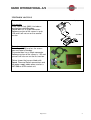
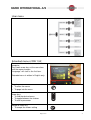
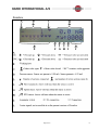
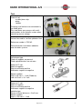
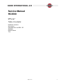
Service Manual
HC2500
679061 - rev. 4
GB – 08.2007
Table of contents:
Hardware versions
User menu
Extended menu of SW 1.52
Scanbox
Default values
Test
Page 1 of 9
1
Hardware versions
There are 2 versions.
Display
First version
From 1999 to July 2003, it includes a
junction box called Scanbox.
Control box has a 20 pin connector.
Software version of the screen is up to
1.30 and it will not run on the second
version.
Scanbox
Second version
From August 2003 and on, the screen
does not need a Scanbox.
The control box has a 39 pin connector.
Software version of the screen is 1.52 and
up and it will also run on the first version.
Picture shows the harness block with
Speed, Flow and Switch connections and
the power supply cable when used as a
HM 1500 on a BK control unit.
Page 2 of 9
2
User menu
User menu
Extended menu of SW 1.52
To access the extended menu, start the
computer.
Press both arrow keys at the same time
until the menu changes.
“Language” will start as the first item.
Extended menu is written in English only.
Page key
• To enter the menus
• To page into the menu
Arrow keys
• To find the desired menu
• To toggle between the choices
• To alter a parameter
•
Accept or Enter key
• To accept the shown setting
Page 3 of 9
3
•
To exit the menu
NOTE: Re-start the system after leaving
the extended menu.
Menu
Function [ choices ]
Normal setting and sets shown in italics
To select language.
[ GB, DK, F, E, D, Cz, SF, NL, I, S ]
To set unit of measurement.
[ Metric, USA ]
To select type of control unit.
[ Present, Not present ]
[ Language ]
[ Unit ]
[ ON/OFF valve ]
For EC: Present
For BK, EVC, EFC & SC: Not present
To select pressure system.
[ Equalisation, No equalisation ]
[ Pressure system ]
For EC & EVC: Equalisation
For EFC: No equalisation
To indicate control box connected.
[Lunch box, Spray box, Not connected ]
[ Control box]
Not connected: BK
Lunch box: Rectangular box with 20 pin
connector.
Spray box: Wave shaped box with 39 pin
connector.
Pre-set tank volume indicated at start-up.
Value is the maximum tanks contents
value.
To calibrate the optional transducer.
Press the page key to go through the 3
items.
[ max., min., offset in mA ]
[ Tank volume max ]
[ Analog adjust ]
For pressure sensor, remove it from the
housing to ensure 0 bar.
It should show 0.0 bar +/- 0.1 bar
To choose the unit of measurement.
Press the page key to go through the
items.
[ Bar, PSI, deg C, deg F, % R.H ]
For the sensitivity of the pressure
regulation valve.
[ Analog unit text ]
[ Regulation con. ]
Page 4 of 9
4
It is a percentage and minus values are
possible.
The higher value makes the pressure
regulation valve more sensitive.
Too high a value will cause oscillation and
excessive wear on the valve.
For EC & EVC: 30%
For EFC: 20%
Sets the minimum power supply to move
the pressure regulation.
Increase the value until the pressure
regulation valve just starts to turn.
Use “page” key to toggle between no
regulation, () increase pressure () and
decrease pressure ().
Use “arrow” keys to raise or lower
percentage until the value begins to turn.
[ Min. press. cycle ]
Normal value for new valve: 10%
To permit change or update of software.
PIN code needed.
Note serial number and contact HARDI.
To reset. PIN code needed.
Note serial number and contact HARDI.
To see total area covered and volume
sprayed.
To change screen contrast, press arrow up
or arrow down keys.
[ Change SW ver. ]
[ Master reset ]
[ Area totals ]
[ Scanbox ]
Factory menu for visual indication whilst
testing for version from 1.09 and on.
It is possible to test or readout signals for:
Line 1
• Pressure up / down
• Working hour
• Main valve ON/OFF
• mAmp for pressure transducer if fitted
Line 2
• Number of sections connected &
number of active sections
• Flow transducer
• Speed transducer
• PTO sensor
• Areameter switch
• Extra 2, 3 & 4
Page 5 of 9
5
Scanbox
Page 6 of 9
6
Default values
Text
[ Language ]
[ Unit ]
[ ON/OFF valve ]
[ Pressure system ]
[ Control box ]
[ Tank size ]
[ Analog adjustment ]
For HC 2500
For HM 1500*
GB
GB
Metric
Metric
Present
Present
Equalisation
Equalisation
Lunch box
Not connected
2000 l
2000 l
max. 10
max. 10
min. 0
min. 0
offset 0 mA
offset 0 mA
Bar
Bar
0%
0%
10%
not relevant
120.0
120.0
1.0000
1.0000
For BK control unit with Spray (control)
box for boom sections set:
[ Control box ] to [Spray box ]
[ Analog unit text ]
[ Regulation con. ]
[ Duty cycle ]
[ Flow PPU ]
[ Speed UPP ]
HM 1500*
For EVC control unit set:
[ ON/OFF valve ] to [ Not present ]
[ Control box ] to [Spray box ]
Page 7 of 9
7
Test
A service tool can easily be made.
It consists of;
a cable joiner strip
plugs
sockets
The plugs and sockets are connected via
the cable joiner.
This now allows easy access with multimeter probes to the metallic screws when
measuring sensor voltage.
Another service tool is a pulse generator
that can be used to simulate speed or flow.
Reference number is 732182.
Extra connectors have been added to
cater for older systems.
Flow sensor
Hall element type
Check all magnets are present.
Check spindle bushes are not worn.
Brown to 12 volt
Black to negative
Blue to multimeter positive
Multimeter negative to negative
Normal readout:
High is 8.0 volt +/- 1 volt (Diode on)
Low is 0.3 volt +/- 0.1 volt
Speed sensor
Brown to 12 volt
Black to negative
Blue to multimeter positive
Multimeter negative to negative
Inductive type
Sensor to metal distance = 3 to 5 mm
Normal readout:
High is 12.0 volt +/- 1 volt
Page 8 of 9
8
Low is 1.4 volt +/- 0.2 volt (Diode on)
Hall Element type
Sensor to magnet distance = 3 to 7 mm
Normal readout:
High is 7.0 volt +/- 1 volt (no magnet)
Low is 0.3 volt +/- 0.1 volt
Date / Revision
01-10-2007 / 04
Section / Subject
General update of whole document
Page 9 of 9
Pages
Written By
AF
9