1
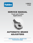
Service
Manual
Truck and
Trailer
Applications
L30033
8/10
Automatic Brake Adjusters
Table of Contents
Operation ........................................................ 1
Brake Adjuster Part Number
and Build Date .............................................. 1
Steer Axle Applications .............................. 2
Drive Axle Applications .............................. 2
Trailer Axle Applications ............................ 3
Warning:
Haldex strongly recommends
routine visual checks be performed at EACH
maintenance service interval. Foundation brake
operational checks utilizing CVSA level 1 applied stroke
criteria should always be utilized. Manual adjustment of
automatic adjusters can disguise hidden problems
within the foundation brake. Brake components such as
S-cams, bushings, return springs, actuators, drums and
adjuster installation MUST be within manufacturer’s
specifications. Adjuster control arms, wear bushings or
attaching hardware that demonstrate visual damage, or
which fail the operational checks, MUST be replaced
immediately. Automatic Adjusters should NEVER be
operated as manual adjusters except as may be
necessary to get the vehicle off the road for service.
Installation Procedures . . . . . . . . . . . . . .4
Routine Visual/Operational Checks . . . .6
Service and Lubrication Intervals . . . . . .6
Foundation Brake Operational
Check and Troubleshooting . . . . . . . . . .7
Brake Adjuster Checking Procedures . .9
Brake Adjuster Operational Check . . . .9
Typical Parts Identification
and Location . . . . . . . . . . . . . . . . . . . . .10
Torque Specifications ..................................11
Frequently Asked Questions.....................12
Additional Parts and
Service Information .....................................13
Important Notice
This symbol is used throughout this manual
to call attention to procedures where
carelessness or failure to follow specific
instructions may result in personal injury
and/or component damage.
The descriptions and specifications contained in this service
publication are current at the time of printing. Haldex Brake
Products Corp. reserves the right to discontinue or modify its
models and/or procedures and to change specifications at
any time without notice.
Operation
The Haldex automatic brake adjuster is a clearance sensing brake adjuster that maintains
When the Brake Applies:
Upon brake application, the brake
adjuster rotates and moves the shoes
into contact with the drum. The
clearance notch corresponds to the
normal lining-to-drum clearance. As the
brake application continues, the rack
moves upward and rotates the one-way
clutch which slips in this direction. As
the brake torque increases, the coil
spring load is overcome and the
wormshaft is displaced axially, releasing
the cone clutch.
Bushing
Clutch Assembly
“O”Ring
Heat Treated
Housing
Direction of Applied
Stroke
Wormshaft
Adjustment
Hex
When the Brake Releases:
When the brake begins its return stroke,
the coil spring load returns to normal
and the cone clutch is again engaged.
The rack is pulled back to its original
position in the notch, and any
additional travel brought about by
lining wear causes the rack to turn the
locked one-way clutch and rotates the
wormshaft through the locked cone
clutch. The wormshaft then rotates the
worm wheel and camshaft, adjusting
the brakes.
Coil Spring
Enclosed
Rack
“O” Ring
Installation
Indicator
Worm Wheel
Clearance
Notch
Control Arm
Fixed Point
Brake Adjuster Identification
Part Number:
409 prefix = Reduced maintenance
adjuster
429 prefix = No-Lube™ adjuster
Serial Number:
First 3 digits = Day of year built
Last 2 digits = Year of build
After
Sept. 1989
The Part No.
P/N40910224
would be our
adjuster part
number
409-10224.
Part Number
P/N40910224
Serial Number
Prior to
Sept. 1989
The first three numbers
stamped on the cover
plate is the brake
adjuster part number.
For example: 224
would be our
adjuster part
number 409-10224.
S/N33489
1
Typical Applications
Steer Axle
Figures 1–4 show
typical brackets for
automatic brake adjuster
applications on steer
axle brake assemblies.
Refer to pages 4 and 5
for detailed installation
procedures.
Figure 1
Steer axle
with clamp
bracket and
flat anchor
stud
Approx. 1/16”
Figure 3
Mack 16,000#
or higher rated
steer axles with
spider mounted
bracket
Figure 2
Steer axle
with clamp
bracket and
round anchor
stud
Figure 4
Steer axle with
strap bracket
Approx. 1/16”
Drive Axle
Figures 5– 8 show
typical brackets for
automatic brake adjuster
applications on drive
axle brake assemblies.
Refer to pages 4 and 5
for detailed installation
procedures.
Figure 5
16° drive
axle with
strap bracket
Figure 6
34° drive
axle with
strap bracket
Figure 7
Mack drive axle
with clamp
bracket and
flat anchor stud
Figure 8
0° Kenworth
drive axle with
strap bracket,
for 8 bag
air ride
2
Note: Refer to fundamental parts identification and location on page 10.
Typical Applications
Trailer Axle
Figures 9–12 show typical brackets for automatic
brake adjuster applications on trailer axle brake
assemblies. Refer to pages 4 and 5 for detailed
installation procedures.
Figure 9
For 16-1/2" Brake Assemblies
Figure 10
For 12-1/4" Brake Assemblies
Figure 11
Integral cam support anchor
bracket for 12-1/4" and 16-1/2"
brakes
Figure 12
Bolt-on cam support anchor
bracket for 12-1/4" and 16-1/2"
brakes
Note: Refer to fundamental parts identification and location on page 10.
3
Installation Procedures
Note: Configuration of anchor bracket and brake adjuster housing may vary,
depending upon axle. Refer to typical applications on Page 2 and 3.
Step 1
Anchor Bracket
Note: Block wheels to prevent vehicle from
rolling. Ensure system tank pressure is
above 100 PSI.
Check that the push rod is fully retracted:
apply air to release spring brake. If air is not
available, spring brake must be manually
caged back.
Install anchor bracket loosely as illustrated
( fig. 13).
Some strap brackets have two mounting
holes. Proper mounting location is
determined by the length of adjuster arm.
5" and 5-1/2" adjuster arm lengths utilize
the shorter hole location while 6" and
6-1/2" length adjusters utilize the longer
hole locations.
Do not tighten anchor bracket fasteners at
this time.
Apply “Anti-Seize” type lubricant to camshaft
splines.
Figure 13
Step 2
Install the brake adjuster onto the camshaft
with the ad justing hex pointing away from
the brake chamber (fig. 14).
Secure the brake adjuster on the camshaft.
Use at least one inner washer and enough
outer washers to allow no more than .060
movement of adjuster on camshaft. (Per
TMC recommended practice RP609-A.)
Note: Do NOT pull push rod out to meet
the brake adjuster.
Rotate the 7/16" adjusting hex nut
CLOCKWISE until the clevis hole lines up
with the brake adjuster arm hole.
4
Apply anti-seize to clevis pin, install and
secure with cotter pin.
Figure 14
Installation Procedures
Step 3
Rotate the control arm away from the
adjusting hex toward the air chamber, until
it comes to a definite internal stop
(fig. 15).
Most adjusters will be equipped with an
“Installation Indicator.” Indicator must fall
within the slot for proper installation with
brakes fully released (fig. 16 ).
If the control arm position is wrong,
tight brakes will occur (fig. 17).
Tighten all anchor bracket fasteners (make
sure the control arm does not move from
its position while tightening fasteners).
Figure 15
Step 4
The adjuster must be manually adjusted
at this time.
Rotate the adjusting hex clockwise until
the lining lightly contacts the drum.
Then back-off the adjuster by turning the
adjusting hex counter-clockwise 1/ 2 of a
turn (fig. 18).
A minimum of 13 ft. lbs. is necessary to
overcome the internal clutch. A ratcheting
sound will be present.
Do NOT use an impact wrench or
internal damage will occur!
FINAL INSPECTION. With full system
air pressure, assure that spring brakes are
released and check that the “Installation
Indicator” is within the slotted area.
IF NOT, REPEAT Step 3.
Correct
(Brakes released)
Figure 16
X
I NCORRECT
(Brakes released)
Figure 17
Figure 18
Note: To ensure proper fit and function,
always replace both adjuster and
mounting bracket.
5
Routine Visual/Operational Checks
Haldex strongly recommends that routine visual/operational checks,
including brackets and control arms, be performed at each Preventative
Maintenance Service Interval.
Adjusters or anchor brackets that have visual damage, or which fail
the operational checks, MUST be replaced immediately.
Automatic adjusters should not be operated as manual adjusters
except as may be necessary to get the vehicle off the road for
service.
Service and Lubrication Intervals
Adjuster
Type
Visual Check
Interval
Manufacture
Date
Lubrication
Interval
Type of
Lubricant
Prior to 6/1/96
50,000 miles or
every 3 months
Standard Chassis
Grease
Each Preventative
Maintenance
Service Interval
Reduced Maintenance After 6/1/96
Adjuster 409-10...
Once a year
Standard Chassis
Grease
Each Preventative
Maintenance
Service Interval
No-Lube™
Adjuster 429-10...
None
Sealed Unit
Each Preventative
Maintenance
Service Interval
Standard
Adjuster 409-10...
After 6/1/96
Notes:
No-Lube™ automatic brake adjusters are manufactured without a grease fitting and are
identified by a 429 prefix.
Moly-disulfide grease should not be used because it may affect the function of the
internal friction clutches and reduce the reliability of the automatic adjustment.
In no case should the lubrication interval exceed the published intervals shown above.
6
Foundation Brake Operational Check and Troubleshooting
Note: Block wheels to prevent vehicle from rolling.
Ensure system tank pressure is at 90-100 psi.
Check that push rod is fully retracted; apply air to release spring brake.
North American Commercial Vehicle Safety Alliance (CVSA)
Uniform Vehicle Inspection Criteria
The applied stroke of the brake should be checked per CVSA guidelines at
90 -100 PSI reservoir pressure. Applied stroke should be at or less than the
specified adjustment limits as follows:
Standard Clamp Type Brake Chamber
Type
Adjustment Limit
Type
Adjustment Limit
9
1-3/8"
24
1-3/4"
12
1-3/8"
30
2"
16
1-3/4"
36
2-1/4"
20
1-3/4"
Long Stroke Type Brake Chamber
Type
Adjustment Limit
Type
Adjustment Limit
16L
2"
24LS
2-1/2"
20L
2"
30LS
2-1/2"
24L
2"
NOTE: Long stroke chambers are identified with square
air ports or port bosses and special trapezoid ID tags.
Free Stroke
Measuring the Free Stroke
Free stroke is the amount of movement of the adjuster arm required to move the brake shoes
against the drum. With brakes released, measure from the face of the chamber to the center of
the clevis pin “A” (fig. 19). Use a lever to move the brake adjuster until the brake shoes contact
the drum “B” (fig. 19). The difference between the fully retracted and drum contact
measurement “B”–“A” (fig. 19), is the free stroke. The free stroke range should fall between
3/8"–3/4".
Free Stroke Within Range
If the free stroke is good, but the applied stroke is too long, there is probably a problem with
the foundation brake. Check the following and reference CVSA out-of-service criteria:
Component
Brake drums
Brake shoes
Brake shoes
Brake shoes
Brake shoes
Cam bushings
Camshaft
Camshaft
Camshaft
Chamber bracket
Clevis yoke and pin
Return springs
Rollers
Rollers
Spider anchor pins
Cause
Cracked or out of round
Shoe span out of spec
Uneven lining wear
Shoe pad missing
Cracked shoes
Excessive movement
Flat spots on cam head
Cracked/broken splines
Worn bearing journals
Broken/bent
Worn
Broken/stretched or missing
Flat spots, grooved pin/worn
Wrong size
Grooved or scored/worn
Action
Replace or check drum run out
Refer to OEM specs and replace if necessary
Check spider concentricity
Remove & replace shoes
Remove & replace shoes
Remove & replace cam bushings per OEM specs
Replace camshaft
Replace camshaft
Replace camshaft
Replace bracket
Remove & replace
Remove & replace springs
Remove & replace roller and pin
Remove & replace with correct parts
Replace spider or pins, as appropriate for OEM
7
Free Stroke Above the Range
If the free stroke is above the range and the applied stroke is too long, there is a problem
with the foundation brake or the adjuster. Check the following:
Component
Cause
Action
Camshaft
Camshaft bushings
Camshaft bushings
Air chamber return springs
Air chamber push rod
Binding
Excessive movement
Binding shaft
Broken, weak, missing
Binding on chamber housing
Air system
Shoe return springs
Automatic brake adjuster
Not exhausting completely
Broken, weak, missing
Unknown
Automatic brake adjuster
Unknown
Remove, replace, lubricate camshaft
Remove and replace cam bushings per OEM specs
Lubricate camshaft bushings or replace
Replace chamber
Check adjuster for proper shimming and air
chamber position for proper adjuster arm length
Check for cause of air problem and repair
Replace springs
Check automatic brake adjuster for proper
installation. Refer to Installation Instructions on
pages 4 & 5.
Refer to Automatic Brake Adjuster Checking
Procedures and Operational Check on pages 9 & 10.
Free Stroke Below the Range
If the free stroke is less than 3/8”, a dragging brake can occur. Check the following:
Component
Cause
Action
Wheel bearing
Automatic brake adjuster
Out of adjustment
Unknown
Automatic brake adjuster
Unknown
Readjust per OEM specs
Check automatic brake adjuster for proper control
arm position. Refer to Installation Instructions on
pages 4 & 5.
Refer to Automatic Brake Adjuster Checking
Procedures and Operational Check on pages 9 & 10.
Free Stroke = B minus A
Applied Stroke = C minus A
A
(Fully Retracted)
B
(Drum Contact Using a Lever)
C
(Brake Application at 90-100 PSI
reservoir pressure.)
8
Figure 19
Stroke Measurements
(taken from face of air chamber
to center of clevis pin)
Automatic Brake Adjuster Checking Procedures
If the brake adjuster is not maintaining the proper applied stroke, before removing the brake
adjuster, check the condition of the foundation brake (see pages 7 & 8). If after inspecting
the foundation brake no apparent problems are found, inspect the automatic brake adjuster
to determine if it is operating properly. The inspection can be performed on or off the vehicle
using the following procedures.
Note: Block wheels to prevent vehicle from rolling.
Ensure system tank pressure is at 90-100 PSI.
Check that push rod is fully retracted; apply air to release spring brake.
If air is not available, spring brake must be manually caged back.
Do not use air tools on brake adjuster!
On Vehicle Inspection
Component
Tight or
dragging brakes
Cause
Control arm
mispositioned
Action
Realign control arm and anchor bracket.
Check installation procedures on pages 4 & 5.
Excessive
chamber push
rod travel
Improper anchor
bracket connection
to control arm
If anchor bracket to control arm connection
is worn, loose, bent or broken, it must be
re-secured or replaced.
Low clutch torque
Rotate the 7/16" adjustment hex one full turn
counterclockwise. Replace brake adjuster if
the torque is less than 13 ft. lbs. or no
racheting sound occurs.
Unknown
Perform automatic brake adjuster
operational check (see below).
Automatic Brake Adjuster Operational Check
Functional operation of the brake adjuster can be performed on the vehicle by using the
following procedure:
Block wheels to prevent vehicle from rolling.
Ensure tank pressure is at 90-100 psi.
Check that the push rod is fully retracted; apply air to release spring brake.
If air is not available, spring brake must be manually caged back.
Manually de-adjust brakes (turn adjustment hex counterclockwise one full turn) to create an
excessive drum to lining clearance condition. (A ratcheting sound should occur.)
Make a full service brake application. On release, allow sufficient time for brake to fully retract.
During the brake release, observe rotation of the adjustment hex (attaching a wrench on the
hex or scribing the hex will make this rotation easier to see).
This rotation indicates that an excessive clearance condition has been determined by the brake
adjuster, and it is making an adjustment to compensate. On each subsequent brake release,
the amount of adjustment and push rod travel will be reduced until the desired clearance is
achieved.
If rotation of the adjustment hex is not observed, refer to Foundation Brake Operational Check
and Troubleshooting Procedures on pages 7 and 8. If foundation brake assembly checks out
okay and hex still does not turn, check control arm and mounting bracket for possible worn,
bent or broken components. If the control arm and mounting bracket check out okay, replace
the adjuster and hardware per procedures on pages 4 & 5.
9
Off Vehicle Inspection
Component
Cause
Action
Adjuster not
functioning
properly
Low clutch
torque
Place adjuster arm in vise. Rotate the 7/16"
adjustment hex counterclockwise one full turn to
check de-adjustment torque. After control arm stops
rotating, a minimum of 13 ft. lbs. will be required
and a ratcheting sound will occur. Replace brake
adjuster if the torque is less than 13 ft. lbs. or no
de-adjustment ratcheting sound is present.
Control Arm
slippage
Place adjuster arm in vise. Rotate the control arm
counterclockwise until the control arm rotates to
an INTERNAL STOP. If the installation indicator
goes past the indicator notch or does not stop
rotating (arm slips freely), replace the brake
adjuster.
Unknown
If torque is above 13 ft. lbs., scribe a line on the
adjustment hex. Manually pull the brake adjuster
control arm clockwise then push back counterclockwise until the installation indicator stops in
the indicator notch. The hex will move in a clockwise
direction when the control arm of the brake adjuster
is pushed back counterclockwise. Replace adjuster if
hex does not move.
Worn/missing
control arm wear
bushing, and
anchor stud pin,
if applicable.
Remove and replace pin and bushings. If adjuster
has passed the above checks, re-install adjuster
on vehicle, with new hardware.
Typical Parts Identification and Location
Anchor
Bracket
Anchor
Stud Pin
Control Arm
(Single Bend)
Anchor
Bracket
Wear
Bushing
10
Anchor
Stud Pin
Adjustment
Hex Nut
Indicator
Notch
Installation
Indicator
Wear
Bushing
Control Arm
(Double Bend)
Torque Specifications
Note: Tighten all fasteners to manufacturer’s recommendations unless
otherwise specified below.
Round Anchor
Stud Pin with
Fabricated Ring
Clamp
Torque to
15-20 ft. lbs.
when installed
Flat Anchor
Stud Pin
Torque to
40-50 ft. lbs.
when installed
Round Anchor Stud
Pin with Slide Nut
Torque to 15-20 ft. lbs.
when installed
3/8"-16 Nut
and Bolt
Torque to 15-20 ft.
lbs. when installed
Strap Style
Bracket
Torque to
8-12 ft. lbs.
when installed
U-Bolt Style
Bracket
Torque to
20-30 ft. lbs.
when installed
11
Frequently Asked Questions
1.
Will the side of the brake adjuster
with the installation indicator
always face in?
No. Haldex adjusters are normally unhanded.
Always install with the adjusting hex pointing
away from the air chamber.
8.
Some brake chambers have round
port openings and some square; what
is the difference?
Standard brake chambers are identified by round
ports. Long stroke chambers are identified by
square ports and trapezoid ID tags.
2.
My adjuster doesn’t have an
installation indicator; should I be
concerned?
No. A few applications aren’t manufactured with
installation indicators. However, the set-up and
function are the same regardless. Refer to pages
4 & 5 for proper installation procedures.
9.
Can I vary the amount of lining-todrum clearance by moving the control
arm?
No, that clearance is set at the factory. If long or
short stroke continues, please refer to the
foundation brake checking procedures on
pages 7 & 8 of this manual.
3.
Why is there resistance when backing
off the adjuster?
It takes approximately 20-25 lb. ft. of torque to
back off the adjustment hex. (A ratcheting sound
should occur.)
10. Can I use an air ratchet on the
adjuster?
No. It will damage the internal mechanism
of the adjuster and render it inoperative.
4.
How far do I back off the automatic
brake adjuster at a brake reline?
1/2 turn. (NOTE: for the first 1/8 turn you may not
hear the ratcheting; this is normal.)
5.
How do I know if I need an offset,
angled or straight-armed adjuster?
Haldex manufactures the right adjuster arm for
your specific application. Haldex adjusters are
unhanded (no lefts or rights) in the majority of
applications. Please refer to the Haldex Parts and
Cross Reference Guide for your specific
application (L00090).
6.
7.
12
Why does my replacement ABA look
different from the original I took off?
The Haldex ABA replacement adjuster has been
designed to fit a number of applications. It is the
same original equipment quality and design of the
adjuster you removed; however, it may look
different on the outside. If you use all the parts
included in the kit, the results will be the same as
the original equipment adjuster.
Why is the applied stroke pressure
range 90-100 psi at the reservoir?
This is the pressure recommended by the CVSA
(Commercial Vehicle Safety Alliance). Anything
beyond 100 psi measures deflection within the
foundation brake and not true push rod stroke.
11. Can I access the adjuster through the
rear cover?
No, do not tamper with the rear cover—it will
release the factory set pressure on the spring and
destroy the adjuster and its ability to properly
function.
12. How much control arm bushing and
anchor stud pin wear is acceptable
before replacement is required?
No more than 1/16."
13. What is the acceptable amount of
camshaft bushing wear?
Automatic adjusters cannot compensate for worn
foundation brake parts. Please refer to the
foundation brake manufacturer’s
recommendations for maximum bushing and
camshaft wear limits.
14. Can wheel bearing adjustment affect
the brake adjuster?
Yes. Improper wheel bearing adjustment could
result in improper brake adjustment. It is necessary
to refer to the axle manufacturer’s wheel bearing
adjustment recommendations. A loose bearing
preload could cause a tight brake.
(continued on page 13)
Frequently Asked Questions (continued)
15. Are all Haldex automatic brake
adjusters pre-lubed?
Yes. All Haldex brake adjusters are lubricated at
the factory. Please consult the Service and
Lubrication Section on Page 6 for proper
lubrication guidelines.
16. Can I use moly lube with the Haldex
automatic brake adjuster?
No. A high concentration of moly-disulfide can
lower the friction capabilities in the adjusting
clutch parts and decrease automatic adjustment
reliability.
18. Does the control arm need to be
properly set and secured?
Yes. Without proper placement and attachment,
the adjuster will not function properly. Make sure
the control arm, anchor bracket and wear items
are in good working order to assure the adjuster
will operate as designed.
19. If automatic adjustment stops, can I
operate as a manual brake adjuster?
No. Completely check out foundation brake and
adjuster to determine cause of problem. Repair
or replace as needed to restore automatic
adjustment.
17. Can I purchase anchor bracket wear
items separately (i.e., anchor stud
pins, wear bushings)?
Yes. Normal wear items like anchor stud pins and
wear bushings are available. Refer to the Haldex
Parts and Cross Reference Guide, L00090.
Otherwise, contact Haldex Technical Assistance
for the appropriate bracket kit at 1-800-643-2374.
Additional Information Available
Additional parts and service information on Haldex Automatic Brake Adjusters may be found in
the following materials:
Service Information
Installation and Maintenance Wall Chart . . . . . . . . . . . . . . . . . . . . . . . . . . . .L60047
Service Manual (Truck/Trailer) . . . . . . . . . . . . . . . . . . . . . . . . . . . . . . . . . . . . .L30033
Installation Tips — Automatic Brake Adjuster (Pocket Size) . . . . . . . . . . . . .L20397
Installation Instructions — AA1 and S-ABA Models . . . . . . . . . . . . . . . . . . . .L31195
Parts Information
Parts and Cross Reference Guide (Truck/Trailer) . . . . . . . . . . . . . . . . . . . . . .L00090
Supplemental Automatic Brake Adjuster Kits . . . . . . . . . . . . . . . . . . . . . . . .L20447
These materials are readily available on the Haldex website www.haldex.com, or you may
order copies by contacting your Customer Service Representative at 1-800-643-2374.
13
Haldex (www.haldex.com), headquartered
in Stockholm, Sweden, is a provider of
proprietary and innovative solutions to
the global vehicle industry, with focus on
products in vehicles that enhance safety,
environment and vehicle dynamics.
Haldex is listed on the Stockholm Stock
Exchange. Haldex has a yearly turnover of
close to 5.6 billion SEK and employs 4,300
people.
Disclaimer: The products described within
this literature, including without limitation,
product features, specifications, designs,
availability and pricing are subject to
change by Haldex and its subsidiaries at
any time without notice.
This document and other information from
Haldex, its subsidiaries and authorized
distributors provide product and/or system
options for further investigation by users
having technical expertise. It is important
that you analyze all aspects of your
application and review the information
concerning the product or system, in the
current literature or catalog. Due to the
variety of operating conditions and
applications for these products or systems,
the user, through their own analysis and
testing, is solely responsible for making the
final selection of the products and systems
and assuring that all performance, safety
and warning requirements are met.
©2010, Haldex AB - This material may contain
Haldex trademarks and third party trademarks,
trade names, corporate logos, graphics and
emblems which are the property of their
respective companies. The contents of this
document may not be copied, distributed,
adapted or displayed for commercial purposes
or otherwise without prior written consent from
Haldex.
Austria
Haldex Wien Ges.m.b.H.
Vienna
Tel.: +43 1 8 69 27 97
Fax: +43 1 8 69 27 97 27
E-Mail: [email protected]
Korea
Haldex Korea Ltd.
Seoul
Tel.: +82 2 2636 7545
Fax: +82 2 2636 7548
E-Mail: [email protected]
Belgium
Haldex N.V.
Balegem
Tel.: +32 9 363 90 00
Fax: +32 9 363 90 09
E-Mail: [email protected]
Mexico
Haldex de Mexico S.A. De C.V.
Monterrey
Tel.: +52 81 8156 9500
Fax: +52 81 8313 7090
Brazil
Haldex do Brasil Ind. e Com. Ltda.
São Paulo
Tel.: +55 11 213 55 000
Fax: +55 11 503 49 515
E-Mail: [email protected]
Poland
Haldex Sp. z.o.o.
Praszka
Tel.: +48 34 350 11 00
Fax: +48 34 350 11 11
E-Mail: [email protected]
Canada
Haldex Ltd.
Cambridge, Ontario
Tel.: +1 519 621 6722
Fax: +1 519 621 3924
E-Mail: [email protected]
Russia
OOO “Haldex RUS”
Moscow
Tel.: +7 495 747 59 56
Fax: +7 495 786 39 70
E-Mail: [email protected]
China
Haldex International Trading Co. Ltd.
Shanghai
Tel.: +86 21 5240 0338
Fax: +86 21 5240 0177
E-Mail: [email protected]
Spain
Haldex España S.A.
Granollers
Tel.: +34 93 84 07 239
Fax: +34 93 84 91 218
E-Mail: [email protected]
France
Haldex Europe SAS
Weyersheim (Strasbourg)
Tel.: +33 3 88 68 22 00
Fax: +33 3 88 68 22 09
E-Mail: [email protected]
Sweden
Haldex Brake Products AB
Landskrona
Tel.: +46 418 47 60 00
Fax: +46 418 47 60 01
E-Mail: [email protected]
Germany
Haldex Brake Products GmbH
Heidelberg
Tel.: +49 6 221 7030
Fax: +49 6 221 703400
E-Mail: [email protected]
United Kingdom
Haldex Ltd.
Newton Aycliffe
Tel.: +44 1325 310 110
Fax: +44 1325 311 834
E-Mail: [email protected]
Hungary
Haldex Hungary Kft.
Szentlörinckáta
Tel.: +36 29 631 300
Fax: +36 29 631 301
E-Mail: [email protected]
Haldex Brake Products Ltd.
Redditch
Tel.: +44 1527 499 499
Fax: +44 1527 499 500
E-Mail: [email protected]
India
Haldex India Limited
Nasik
Tel.: +91 253 2380094
Fax: +91 253 2380729
USA
Haldex Brake Products Corp.
Kansas City
Tel.: +1 816 891 2470
Fax: +1 816 891 9447
E-Mail: [email protected]
Italy
Haldex Italia Srl.
Biassono (Milan)
Tel.: +39 039 47 17 02
Fax: +39 039 27 54 309
E-Mail: [email protected]
www.haldex.com
Commercial Vehicle Systems
L30033 US 8/10 2M ALP (Last Rev. 5/07)


![Trailer Roll Stability (TRS) Installation Manual [L30040]](http://vs1.manualzilla.com/store/data/006020641_1-040a22153212ab13bbec744ca183c148-150x150.png)