1
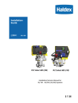
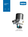
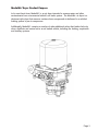
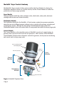
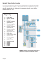
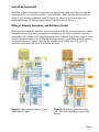
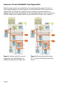
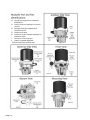
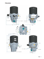
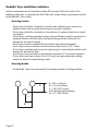
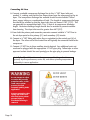
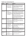
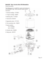
Installation
Guide
L31241
10/08
Haldex ModulAir®
Installation / Service Manual
Technical Service
and
Engineering Support
In the U.S. please call:
1-800-643-2374 (press 2)
In Canada, please call:
1-800-267-9247
www.haldex.com
www.hbsna.com
IMPORTANT NOTICE
The data listed herein is correct to the best of Haldex’s knowledge and belief, having been
compiled from reliable and official sources of information. However, HALDEX CAN NOT
ASSUME ANY RESPONSIBILITY for possible error or misapplication of the product. Final
determination of the suitability of the products for the use contemplated by the Buyer is the
sole responsibility of the Buyer. Haldex shall have no responsibility in connection with this
suitability.
IMPORTANT NOTICE
The description and specifications contained in this Installation Manual are current at the
time of printing. Haldex Brake Products Corp. reserves the right to discontinue or modify
its models and/or procedure and to change specifications at any time without notice.
Page 1
Table of Contents
Section
Page
ModulAir® Dryer Purpose, Anatomy and Function
Product Purpose . . . . . . . . . . . . . . . . . . . . . . . . . . . . . . . . . . . . . . . . . . . . . . . . . . . . . . . . . . .3
Product Anatomy . . . . . . . . . . . . . . . . . . . . . . . . . . . . . . . . . . . . . . . . . . . . . . . . . . . . . . . . . . .4
Product Function . . . . . . . . . . . . . . . . . . . . . . . . . . . . . . . . . . . . . . . . . . . . . . . . . . . . . . . . . . .6
Technical Data . . . . . . . . . . . . . . . . . . . . . . . . . . . . . . . . . . . . . . . . . . . . . . . . . . . . . . . . . . . . .9
ModulAir® Dryer Installation Guidelines . . . . . . . . . . . . . . . . . . . . . . . . . . . . . . . . . . . . . . . . . . .12
ModulAir® Dryer Troubleshooting Guide . . . . . . . . . . . . . . . . . . . . . . . . . . . . . . . . . . . . . . . . . .18
ModulAir® Dryer Service Parts Kit Information . . . . . . . . . . . . . . . . . . . . . . . . . . . . . . . . . . . . .19
Page 2
ModulAir® Dryer Product Purpose
In its most basic form, ModulAir® is an air dryer intended to remove water and other
contaminants from a commercial vehicle’s air brake system. The ModulAir® air dryer is a
desiccant style dryer that removes moisture from compressed air delivered to a vehicle’s
braking system by an air compressor.
Additionally, ModulAir® contains a number of other additional valves that further help dry,
clean, distribute and control air to an air braked vehicle, including the braking, suspension
and auxiliary systems.
Page 3
ModulAir® Dryer Product Anatomy
The ModulAir® dryer consists of three main modules; the Dryer Module, for drying; the
Distribution Module to deliver air to brake circuits; and the Control Module to control air
production and dryer purge operation
Dryer Module
The Dryer Module holds the turbo protection valve, check valve, safety valve, desiccant
cartridge with canister and heater assembly.
Distribution Module
The Distribution Module for the ModulAir® 4-Circuit version contains four pressure protection
valves that are set at different pressure settings to give a priority to the primary, secondary and
remaining two circuits. Although the dryer purges contaminants through a hole in the
Distribution Module it does not contain valves or components that control the dryer purge cycle.
Control Module
The Control Module on the standard version of ModulAir® consists of a typical piston air
governor that is pre-set to cut-in and cut-out pressures. Other versions of the ModulAir®
Control Module include various electronic controls for governor, circuit pressure monitoring
and control, and air dryer purge cycle.
Desiccant Cartridge, Canister
and Mounting Collar
Turbo Protection Valve
Unloader or
Purge Valve
Dryer
Module
Governor
Control
Module
Distribution
Module
Safety Valve
Heater
Regeneration Valve
Figure 1: ModulAir® Exploded View
Page 4
Desiccant Cartridge, Canister and Mounting Collar
The desiccant cartridge is where all drying and contaminant removal occur in the air dryer.
The Haldex ModulAir® dryer contains the Haldex patented MTC cartridge design which has
five separate stages of drying. The desiccant cartridge is covered by the canister and affixed
to the dryer base with the mounting collar and four bolts.
Turbo Protection Valve
The turbo protection valve, located at the dryer inlet, prevents turbo pressure loss on
turbocharged compressor applications when compressor in unloaded.
Governor
A standard pneumatic piston-style governor is used in ModulAir® to control the cut in and cut
out pressures in the air system. The governor signals the compressor to load or unload.
Safety Valve
The safety, or pop off valve, is designed to relieve system pressure if it reaches a level higher
than normal operating pressures. This protects other brake system components from high
pressures that could cause system damage or failure.
Unloader/Purge Valve
The unloader/purge valve in ModulAir® is essentially a purge valve. When the dryer is ready
to purge, the unloader/purge valve opens to allow all contaminants collected within the
dryer and cartridge to be flushed out through the purge port on the dryer.
Regeneration Valve
The regeneration valve serves as a timer to allow a designated amount of air to flow from the
air brake system back through the ModulAir® dryer in order for it to purge and regenerate the
desiccant.
Heater
A heater helps prevent moisture collected within the air dryer from freezing. The integrated
thermostat on the heater controls when the heater is energized.
Page 5
ModulAir® Dryer Product Function
In an unpressurized state, all valves internal to the ModulAir® assembly should be in the
closed position as shown in Figure 2. This includes the turbo protection valve (T), safety
valve (S), unloader valve (U), check valve (C), regeneration valve (R) and all pressure
protection valves (O1...O4).
Diagram Key:
C ...
D ...
G ...
O1 . . .
Check valve
Air dryer cartridge
Governor
Pressure protection
valve circuit 21
O2 . . . Pressure protection
valve circuit 22
O3 . . . Pressure protection
valve circuit 23
O4 . . . Pressure protection
valve circuit 24
R . . . Regeneration valve
S . . . Safety valve
T . . . Turbo protection valve
U . . . Unloader valve
11 . . . Incoming air from
compressor
21 . . . Primary circuit
22 . . . Secondary circuit
23 . . . Auxiliary 1
24 . . . Auxiliary 2
3 . . . Exhaust
4 . . . Control
Figure 2: ModulAir® dryer and air system with no
pressure in the dryer or the air brake circuits
Page 6
Start of Air System Fill
When the engine is first started, compressed air from the air compressor flows through the
discharge line to the inlet port marked 11 on ModulAir®. When the inlet pressure gets to
about 44 psi, the turbo protection valve (T) opens and allows air to flow through the
desiccant cartridge (D) and the check valve (C) opens as seen in Figure 3.
Filling of Primary, Secondary, and Auxiliary Circuits
As the pressure within the ModulAir® dryer continues to build, the pressure protection valves
that control air to the primary, secondary and auxiliary circuits begin to open in sequence
according to their factory preset opening pressures (see Technical Data section page 9). Each
pressure protection valve is set at different opening pressure to give filling preference to one
or more circuits versus others. Typically, the primary circuit is filled first, so its pressure
protection valve would be set to open before all others.
Figure 3: Turbo protection valve (T) and
check valve (C) open
Figure 4: All pressure protection valves
(O1…04) open and filling primary brake
circuits
Page 7
Compressor Cut-out and ModulAir® Dryer Regeneration
When the system pressure has reached the set cut-out pressure, the governor (G) sends a
control signal through port 4 to the compressor so that it will unload. At the same time, the
unloader valve (U) receives this control line pressure, causing it to open and allow air to
backflow from the air brake circuits (figure 5). The regeneration valve (R) serves as a timer that
will allow sufficient air to backflow from the brake circuits before closing as seen in figure 6.
Figure 5: Unloader valve (U) open and
regeneration valve (R) allowing air to
backflow through dryer for purge cycle
Page 8
Figure 6: All pressure protection valves
(O1…04) open and filling primary brake
circuits
Technical Data for ModulAir® Dryer
Air Flow
Maximum inlet airflow
Typical inlet airlflow
=
=
35 scfm (991 slpm)
12 scfm @ 125 psi, 160º F
(340 slpm @ 8.6 bar, 71ºC)
Temperature
Maximum operating range
Recommended operating range
=
=
-40°F to +175°F (-40°C to +80°C)
+40°F to +150°F (+5°C to +65°C)
Pressure
Governor settings
Cut-in pressure
Pressure range
=
=
105 ± 5 psi (7.25 ± 0.35 bar)
22.5 ± 7.5 psi
(1.55 ± 0.5 bar)
Safety valve opening pressure
Burst pressure
=
=
175 + 14 psi
(12 + 1 bar)
360 psi
(25 bar)
Turbo protection valve
Opening pressure
Closing pressure
=
=
44 ± 8 psi
22 ± 3 psi
Pressure protection valves
Opening pressure primary circuit (21)
Closing pressure primary circuit (21)
=
=
103 ± 3 psi (7.1 ± 0.2 bar)
82 psi
(5.7 bar)
Opening pressure secondary circuit (22) =
Closing pressure secondary circuit (22) =
109 ± 3 psi (7.5 ± 0.2 bar)
87 psi
(6.0 bar)
Opening pressure auxiliary circuit 1 (23) =
Closing pressure auxiliary circuit 1 (23) =
55 ± 3 psi
42 psi
(3.8 ± 0.2 bar)
(2.9 bar)
Opening pressure auxiliary circuit 2 (24) =
Closing pressure auxiliary circuit 2 (24) =
84 ± 3 psi
66 psi
(5.8 ± 0.2 bar)
(4.6 bar)
(3 ± 0,5 bar)
(1.5 ± 0.2 bar)
Maximum Inlet Airflow
=
about 35 SCFM ( about 990 SLPM)
Electrical
Nominal voltage
Power consumption
Resistance Amperage
=
=
=
12 or 24 V DC
90 Watt
8 amps @ 12V / 4 amps @ 24V
Weights
Assembly weight
Desiccant cartridge weight
=
=
about 20.0 lbs (about 9.1 Kg)
about 3.5 lbs (about 1.6 Kg)
Torque Values
Cannister bolts
Governor bolts
Heater screw
=
=
=
32 - 35 lbf - ft (43 - 47 Nm)
110 - 150 lbf - in (11.5 - 13.8 Nm)
45 - 55 lbf - in (5.1 - 6.2 Nm)
Loctite Note: Loctite blue should be used very sparingly and Loctite red should never be
used.
Page 9
Page 10
Dimensions
Page 11
ModulAir® Dryer Installation Guidelines
Haldex recommends that all installations follow SAE standard J2383 and much of the
following information is extracted from SAE J2383, with certain unique requirements specific
to the ModulAir® dryer family.
Mounting Position
• The air dryer should be mounted in a location with sufficient space around it to
facilitate service and to provide visual access for periodic inspection.
• The air dryer should be mounted in an area where it is protected from tire or wheel
road splash.
• The air dryer, including mounting brackets, lines and fittings should be mounted in a
protected location such that minor mechanical damage to the vehicle will not
damage the air system integrity.
• The air dryer must be mounted with the exhaust port pointed downward.
• The air dryer must be mounted to avoid excessive heat sources (175º F max).
• The air dryer mounting method must be rigid enough to avoid vibration which could
damage the desiccant or dryer.
• The air dryer must not incline in any direction more than 15° from vertical position.
• The air dryer must have at least 0.5 in (12.5 mm) free space above the cartridge
canister to allow for removal during service.
Mounting Method
• The ModulAir® dryer uses the standard 3-bolt pattern shown in the figure below.
A
c
B
Page 12
A= 2.83 in (72mm)
B = 4.13 in (105mm)
C = 2.07 in (52.5 mm)
Drill Clearance Hole Diameter
for 1/2”—UNC 28 Bolt
Air Lines and Fittings
Air Lines
• To prevent moisture accumulation, the compressor discharge line should slope
continuously downhill from the compressor to the dryer without any dips which
exceed ½ the line diameter. If this is not possible, the line should run vertically
straight upward at the compressor to a height that will permit a downhill sloping run
to the dryer.
• The compressor discharge line size, length, and material must be such that the inlet
temperature is typically no more than 160°F (71°C), and no less than 77°F (25°C)
above the lowest ambient temperature. Lower dryer inlet temperatures should be
avoided to minimize the risk of freeze-ups in the discharge line or dryer inlet fitting.
Higher dryer inlet temperatures should be avoided to minimize the risk of heat
damage to the dryer seals and/or to avoid loss of drying performance.
Fittings
• The use of restrictive fittings in the compressor discharge line should be avoided.
These restrictive fittings impede the airflow and contribute to increased freezing
potential. Avoid the use of 90° elbows where possible
• The air dryer must not incline in any direction more than 15° from vertical position.
• The air dryer must have at least 0.5 in (12.5 mm) free space above the cartridge
canister to allow for removal during service.
• Use Teflon tape on fittings very sparingly, keeping in mind that it could break loose
and contaminate the air valve seals.
Page 13
ModulAir® Dryer Installation Guidelines
Important Precautions and Preparations
• All company and vehicle manufacturer’s safety procedures must be
followed when installing the ModulAir® dryer.
• Always wear proper personal protective equipment, including approved
eye glasses.
• Never work on or under a vehicle unless it is parked on a level surface
and its wheels are blocked to prevent it from moving.
• Never work on a vehicle air brake system when the engine is running.
Where circumstances require that the engine be in operation, extreme
caution should be used to prevent personal injury resulting from
contact with moving, rotating, leaking, heated or electrically charged
components.
• Drain all air pressure from the air system before beginning any
installation, service, or repair.
• Never connect or disconnect a hose or line containing pressure. Never
remove a component plug unless it is certain that all system pressure
has been depleted.
• Never exceed recommended component or system pressures.
• Do not attempt to install, remove, disassemble or assemble a
component until all recommended procedures have been read and are
fully understood. Use only the proper tools and observe all precautions
pertaining to the use of those tools.
• Use only genuine Haldex replacement parts, components and kits.
Replacement hardware, tubing, fitting, etc should be of equivalent size,
type and strength as original equipment and be designed specifically
for such applications and systems.
• Components with stripped threads or damaged part should be replaced
rather than repaired. Repairs requiring machining or welding should
not be attempted unless specifically approved and stated by the vehicle
or component manufacturer.
• Prior to returning the vehicle to service, make certain all components
and systems are restored to their proper operating condition.
Page 14
Mounting Guidelines
1. Locate ModulAir® dryer in an area with sufficient space that will allow for service
and visual access for inspection.
2. Dryer should be mounted away from direct tire splash.
3. The dryer exhaust, or purge port must point downward. Reference page 10.
4. Mounting location must be selected to avoid excessive heat.
5. Mounting location must be rigid and not susceptible to excess vibration.
6. Compressor discharge line must slope downward, without dips and 90° fittings
should be avoided.
7. Mounted dryer should not have more than 15° inclination from vertical.
8. Ensure that there is a minimum of ½” above dryer for serviceability of the desiccant
cartridge.
9. The ModulAir® dryer has a standard SAEJ2383 3-bolt mounting pattern and can be
used to mount directly to a frame member. However, a mounting bracket can be
used if necessary.
Basic Installation Steps
Mounting
1. Park the vehicle on a level surface, apply the parking brakes and always block the
wheels.
2. Stop the engine.
3. Drain the air pressure from all reservoirs before beginning any work on the vehicle.
4. Following the vehicle manufacturer’s recommended procedures, deactivate the
electrical system in a manner that removes all electrical power from the vehicle.
5. Locate the dryer to the intended mounting position in accordance with the above
mounting guidelines and install ½” - 28 minimum grade 5 bolt with lock washer,
tightening to 45-55 ft-lb of torque.
Electrical
6. For those dryers with a heater, it must be connected to the vehicle power supply.
Locate a circuit with the correct voltage that is energized, or “hot,” when the
ignition is “ON.” The current draw is 8 amps at 12 V and 4 amps at 24 V. A 10-15
amp fuse is recommended in this line. Connect the one heater lead to this “hot”
wire.
7. Connect the other heater lead to a good electrical ground on the vehicle chassis or
within an electrical junction box. Care should be taken to protect the grounding
connection from the water and other contaminant ingression.
Page 15
Connecting Air Lines
8. Connect a suitable compressor discharge line to the ½” NPT dryer inlet port
marked 11, making sure that the line slopes down from the compressor to the air
dryer. The compressor discharge line material should be wire braided “Teflon”
hose, copper tubing or a combination of both. The length of compressor discharge
line should be selected so that the dryer inlet does not exceed 170°F (77°C). This
can generally be accomplished with 12 to 15 feet of air compressor discharge
length. Excessive discharge length should also be avoided to prevent moisture
from freezing. The dryer inlet must be greater than 40°F (5°C).
9. From both the primary and secondary reservoirs connect suitable ½” NPT line to
the air dryer ports for the primary (21) and secondary (22) circuits.
10. Connect a ¼” NPT fitting with nylon line or equivalent to the control port (4) of
the dryer. The other end of the control line will typically be connected back to the
compressor.
11. Connect ¼” NPT line to those auxiliary circuits desired. Any additional ports not
used can be plugged with the appropriate ¼” NPT pipe plug. Teflon tape or other
approved sealant should be used sparingly on the pipe plug to prevent leakage.
Installation Tip: While minimum diameters are specified, larger line diameters
generally improve performance, service life, and reduce operating temperatures,
particularly in severe applications.
Do not attempt to adjust
or service the pressure
protection valve, as this
could cause system
pressure loss and
automatic parking brake
application.
Pressure protection valve
springs are under load
and could cause serious
personal injury if
distribution housing is
removed.
Page 16
Testing the ModulAir® Dryer
Before placing the vehicle into service, perform the following tests:
1. Close all reservoir drain valves and ensure all lines are connected properly.
2. Assure transmission is in neutral, start engine. Build up system air pressure to
governor cut-out and note that the air dryer purges with an audible exhaust of air.
Air should continue to flow from the dryer exhaust as the dryer purges and
regenerates the desiccant for approximately 20 - 30 seconds.
Testing Tip: The pressure gauges for the primary, secondary and auxiliary
circuits will begin to fill at different pressures. Typically, the primary will fill first,
with the secondary and auxiliaries to follow shortly after.
3.
Actuate the service brakes a number of times to reduce system air pressure to
governor cut-in. Ensure that the system once again builds to full required system
pressure and that the dryer purges when the compressor cuts out (compressor
unloads).
4. It is recommended that the vehicle be tested for leakage using the following
procedure to assure that the air dryer will not cycle excessively:
A. Apply the parking brakes, run engine to build system pressure to governor
cut-out and allow pressure to stabilize for at least 1 minute at idle.
B. Observe the dash gauge pressures for 2 minutes and note any pressure
drop. Pressure drop should not exceed 4 psi with brake pedal released and
6 psi with brakes applied. Any noticeable leakage must be repaired to avoid
excessive cycling.
C. On vehicles using “system regeneration,” which is how the ModulAir® dryer
functions, the vehicle air gauges will drop slightly as the dryer purges.
5. Charge cycle time: during normal, daily operation, the compressor should recover
from governor cut-in to governor cut-out in 90 seconds or less depending upon the
engine RPM and vehicle vocation.
6. Purge cycle interval: During normal vehicle operation, the air compressor must
remain unloaded for a minimum of 30 seconds between charge cycles. This
minimum purge time is required to ensure complete regeneration of the desiccant.
Page 17
ModulAir® Dryer Troubleshooting Guide
Problem
Cause
Solution
Water in air system
1. Desiccant contaminated
(oil) or over saturated.
1. Replace desiccant cartridge. Wipe dryer base clean
Check compressor for excessive oil passage.
2. Leaks in air system.
2. Tighten air connections. Use soapy water to
recheck for leaks following the Testing the
ModulAir® Dryer section.
3. Governor loose or not
functioning properly.
3. Check governor gasket for damage and replace if
necessary. Reassemble governor and tighten
governor bolts to recommended manufacturer’s
torque specifications.
Constant exhaust of
air at air dryer
1. Dryer unloader valve not
closing.
2. Governor loose or not
functioning properly.
3. Compressor unloader not
functioning (compressor
not unloading).
1. At compressor cut-out there must be a slight blow
of regenerated air from the exhaust port of the
dryer for approx. 20 -30 seconds. If air flow
continues, after purge cycle, remove and inspect
unloader valve of the dryer for obstruction or
damage. If damaged, then replace. If obstructed
or dirty, then clean and reinstall.
2. Check governor gasket for damage and replace if
necessary. Reassemble governor and tighten
governor bolts to recommended manufacturer’s
torque specifications 110 - 150 lb in.
3. Repair or replace compressor unloader.
Excessive
compressor cycling
1. Excessive leaks in air
system.
1. Tighten air connections, soap connection and
recheck for leaks.
2. Broken, contaminated or
defective unloader valve.
2. Clean or replace compressor unloader valve.
3. Undersized compressor,
duty cycle of compressor
should not exceed 25%.
Safety valve is open
1. Desiccant cartridge is
plugged or overly
contaminated.
2. Ice blockage inside dryer.
3. Reduce air demand or use a compressor with
greater air output.
1. Excessive oil passage from compressor or high
amount of carbon buildup. Check for worn
compressor (piston rings, gaskets, etc.). Replace
desiccant cartridge.
3. Excessive system
pressure.
2. Check heater function.
Short life of dryer or
desiccant cartridge
1. Air at inlet of dryer
exceeds 170°F (77°C).
1. Extend length of compressor discharge line; see
Installation Guidelines and Installation Procedure
sections. The 170°F (77°C) dryer inlet temperature
can usually be achieved with 12’ to 15’ of
compressor discharge line.
Short purge cycle of
dryer (less than 12
seconds)
1. Loose governor or poor
gasket seal.
1. Tighten governor bolts. If leakage still occurs, then
replace gasket or complete governor.
2. Regeneration valve not
functioning.
2. Replace regeneration valve.
Page 18
3. Repair or replace governor.
ModulAir® Dryer Service Parts Kit Information
General Instructions
The following parts are available for service and maintenance
of the ModulAir® dryer. Each service kit includes specific
instructions.
1. Desiccant cartridge: 47178964
2. O-ring for cartridge: DQ6054
3. Retaining collar: 47171868
4. Governor kit: KN18541
5. Regeneration valve: 47177434
6. Turbo protection valve: DQ6055
7. Heater assembly:
12V: 47110020
24V: 47110021
8. Unloader valve: DQ6056
9. Safety valve: KN31527
Page 19
Notes:
Page 20
Haldex offers proprietary vehicle technology solutions to the global vehicle industry within specific niches. We focus on products to improve
safety, the environment and vehicle dynamics.
We are enhancing our competitive capabilities
and building long-term customer relationships
through high performance, low total costs to the
customer through the product’s service life, ethical business practices and commitment to
long-term partnerships. Haldex operations are
divided into four business areas: Commercial
Vehicle Systems, Hydraulic Systems, Garphyttan
Wire and Traction Systems.
Austria
Haldex Italia SRL
Biassono (Milan)
Tel.: +39 039 471 702
Fax: +39 039 27 54 309
E-Mail: [email protected]
Belgium
Poland
Haldex N.V./S.A.
Balegem (Ghent)
Tel.: +32 9 363 90 00
Fax: +32 9 363 90 09
E-Mail: [email protected]
Haldex Sp. z.o.o.
Praszka
Tel.: +48 34 350 11 00
Fax: +48 34 350 11 11
E-Mail: [email protected]
Brazil
Russia
Haldex do Brasil Ind. e Com, Ltda.
São Paulo
Tel.: +55 11 213 55 000
Fax: +55 11 503 49 515
E-Mail: [email protected]
OOO Haldex RUS
Moscow
Tel.: + 7 495 747 59 56
Fax: +7 495 786 39 70
E-Mail: [email protected]
Canada
South Korea
Haldex Ltd
Guelph, Ontario
Tel.: +1 519 826 7723
Fax :+1 519 826 9497
E-Mail: [email protected]
Haldex Korea Ltd.
Seoul
Tel.: +82 2 2636 7545
Fax: +82 2 2636 7548
E-Mail: [email protected]
China
Spain
Haldex International Trading Co. Ltd.
Shanghai
Tel.: +86 21 5240 0338
Fax: +86 21 5240 0177
E-Mail: [email protected]
Haldex España S.A.
Parets del Valles (Barcelona)
Tel.: +34 93 573 10 30
Fax: +34 93 573 07 28
E-Mail: [email protected]
France
Sweden
Haldex Europe SAS
Weyersheim (Strasbourg)
Tel.: +33 3 88 68 22 00
Fax: +33 3 88 68 22 09
E-Mail: [email protected]
Haldex Brake Products AB
Landskrona
Tel.: +46 418 47 60 00
Fax: +46 418 47 60 01
E-Mail: [email protected]
Germany
United Kingdom
Haldex Brake Products GmbH
Heidelberg
Tel.: +49 6221 7030
Fax: +49 6221 703400
E-Mail: [email protected]
Haldex Ltd.
Newton Aycliffe
Tel.: +44 1325 310 110
Fax: +44 1325 311 834
E-Mail: [email protected]
Hungary
Haldex Brake Products Ltd.
Redditch
Tel.: +44 1527 499 499
Fax: +44 1527 499 500
E-Mail: [email protected]
Haldex Hungary Kft.
Szentlörinckáta
Tel.: +36 29 631 300
Fax: +36 29 631 301
E-Mail: [email protected]
©2008, This material may contain Haldex
trademarks and third party trademarks, trade
names, corporate logos, graphics and emblems
which are the property of their respective companies. The contents of this document may not
be copied, distributed, adapted or displayed
for commercial purposes or otherwise without
prior written consent from Haldex.
Italy
Haldex Wien Ges.m.b.H.
Vienna
Tel:: +43 1 8 65 16 40
Fax: +43 1 8 65 16 40 27
E-Mail: [email protected]
India
Haldex India Limited
Nasik
Tel.: +91 253 2380094
Fax +91 253 2380729
E-Mail: [email protected]
Commercial Vehicle Systems
L31241 US 10/08 ?? ??
USA
Haldex Brake Products Corp.
Kansas City, MO
Tel.: +1 816 891 2470
Fax: +1 816 891 9447
E-Mail: [email protected]
www.haldex.com
www.hbsna.com

![Trailer Roll Stability (TRS) Installation Manual [L30040]](http://vs1.manualzilla.com/store/data/006020641_1-040a22153212ab13bbec744ca183c148-150x150.png)