1
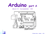
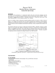
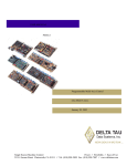
ISOCOMP I
GAMMA COUNTER
AND
DATA REDUCTION SYSTEM
SERVICE MANUAL
MGM INSTRUMENTS
925 SHERMAN AVENUE
HAMDEN, CT 06514 U.S.A.
(203) 248-4008
(800)-551-1415
http://www.mgminstruments.com
e-mail: [email protected]
INTRODUCTION...................................................................................................................3
Specifications ..........................................................................................................................3
Function Keys.........................................................................................................................4
CALIBRATION......................................................................................................................5
SAMPLE PRINTOUT ............................................................................................................9
TEST PROTOCOL PRINTOUT ..........................................................................................13
TROUBLESHOOTING........................................................................................................14
TEST POINTS.......................................................................................................................15
COVER REMOVAL............................................................................................................15
COMPONENT REPLACEMENT.......................................................................................16
FUSE REPLACEMENT ......................................................................................................16
KEYBOARD REPLACEMENT..........................................................................................17
DISPLAY REPLACEMENT...............................................................................................17
PRINTER REPLACEMENT ...............................................................................................18
MAIN PCB REMOVAL/REPLACEMENT.......................................................................18
REMOVAL/REPLACEMENT OF PRINTER POWER SUPPLY ...................................19
DETECTOR REPLACEMENT...........................................................................................20
SCHEMATICS .....................................................................................................................22
Note on schematics: In the Adobe Acrobat format of this manual, the schematics are
scalable. If the schematics are printed on 8½” by 11” paper, they are unreadable. To print
the schematics so that they are readable, select the print function in the Adobe Acrobat
reader, and print only the schematic pages to a printer capable of printing on 11” by 17”
paper.
If a printer capable of printing on 11” by 17” paper is not available, then by zooming in
the Adobe Acrobat reader, the schematics can be viewed quite nicely.
ISOCOMP I SERVICE MANUAL
INTRODUCTION
The ISOCOMP I Gamma Counter and Data Reduction System is the latest in a long line
of compact yet powerful bench top laboratory instruments form MGM Instruments. A
1.5 inch square Sodium Iodide Crystal turns the gamma radiation emitted from a sample
containing 125I or 57CO into an electrical pulse that is amplified and counted by the
computer in the Main PCB. Menu driven instructions prompt the user to insert the correct
tube and press the proper keys from calibration, to programming, to operation.
Protocols may be programmed and stored in permanent non-volatile memory. Data
reduction routines are selected by the user during programming (see Operator’s Manual
for programming instructions and further information on the data reduction routines.)
Types of test that can be performed include; RIAs, IRMAs, Uptakes, screening etc.
Simultaneous 125I and 57CO counting is also possible for applications such as a B12/Folate
assay.
Instrument calibration is performed automatically by the internal microprocessor, and
results are printed by the on board thermal graphics printer. A calibration standard is
required to perform instrument calibration and is available through MGM Instruments.
The ISOCOMP I is operated either via the 20 key multi-function keypad on the front
panel or remotely by a computer or terminal, utilizing the RS-232 Serial Interface. Results
are reported via the 20 character vacuum florescent display on the front panel, the 20
column graphics printer, or through the RS232 interface.
Specifications
Detector
1.5” x 1.5” NaI (thallium doped) crystal
125 I Efficiency
> 75%
Isotope Windows
125
I - 20 to 75 Kev
CO - 100 to 200 Kev
57
Crossover of 57CO
into 125I window
>3% at 0.038 µCi of 57CO
Background
125
I - Less than 100 CPM
CO - Less than 200 CPM
57
Vial Size
Up to 16 mm diameter
Page 3 of 24
ISOCOMP I SERVICE MANUAL
Power Requirements
120 TO 240 VAC Selectable
50 or 60 Hz
Operating Temperature
+10 to +40 degrees C
+50 to +105 degrees F
Dimensions
Height:
Width:
Depth:
Weight
24 Pounds
4”
15”
11”
Front Panel Controls
The ISOCOMP is controlled by function keys located to the right of the numeric keys on
the Front Panel Keypad.
7
8
9
COUNT
START
4
5
6
STAT
PROG
1
2
3
RESUM
LIST
0
.
CLEAR
ENTER
CAL
Function Keys
COUNT
INITIATES A COUNT SEQUENCE
STAT
INTERRUPTS A CURRENT PROTOCOL TO RUN A STAT ASSAY
RESUME
RESUMES INTERRUPTED PROTOCOL
ENTER
ACCEPTS DISPLAYED DATA
START
BEGINS A NEW PROTOCOL
PROG
EDITS PROTOCOL PARAMETERS
LIST
PRINTS A LIST OF PROTOCOL PARAMETERS
CAL
INITIATES A CALIBRATION ROUTINE
Page 4 of 24
ISOCOMP I SERVICE MANUAL
CALIBRATION
The Isocomp I gamma counter has the ability to self calibrate utilizing a calibration source
of either 125I or the long life, mock 125I (129I) which is recommended.
To Calibrate the instrument:
Press the CAL button on the front panel keypad. The following is displayed
ISOCOMP I SN: 105000
ENTER TO ACCEPT
The instrument serial number will be displayed. If the serial number is correct, press
ENTER. If it is not correct, enter the proper serial number and press ENTER. The
following is displayed.
ISOCOMP I CALIBRATE?
PRESS 0=NO, 1=YES
Press 1 to initiate a calibrate sequence. The following is displayed:
INSERT CAL SOURCE
PRESS COUNT
The instrument prompts the user to insert a source. Insert the calibration source and press
ENTER.
The instrument will take approximately 1 minute to complete its calibration. At the
conclusion of a successful calibration, a calibration number will be printed, and the
following will be displayed:
BACKGROUND COUNT?
PRESS 0=NO, 1=YES
Press 1 to perform a background check. The Isocomp will take 10-1 minute counts and
store the average of the backgrounds for 125I and 57CO in memory for use (if desired)
during an assay utilizing the background subtract parameter.
Page 5 of 24
ISOCOMP I SERVICE MANUAL
Consult operator’s manual for more information. After the background count is
complete, the following will be displayed.
EFFICIENCY TEST?
PRESS 0=NO 1=YES
Press 0 to skip the efficiency test. Press 1 to perform the efficiency test. If 1 is pressed,
the following is displayed:
ACTIVITY (uCi)=?
Enter the activity of the calibration source. If the source was purchased from MGM, there
will be two numbers printed on the label on the tube. Enter the SIMULATED activity as
is printed on the label.
Simulated
Contains
0.061
0.085
uCi 125I
uCi 129I
ENTER THIS
NUMBER
The following will be displayed:
INSERT SOURCE
PRESS COUNT
The instrument will perform 10-1 minute counts of the calibration source. After the last
tube has been counted, the printer will report the average counts, efficiency, chi2 and
report that efficiency is complete. The display will return to the main menu and the
instrument is ready to be operated.
Page 6 of 24
ISOCOMP I SERVICE MANUAL
NOTE: It is recommended that calibration be performed weekly and the printouts saved
to be able to track the performance of the instrument.
**********************
ISOCOMP QA PROCEDURE
SERIAL
#
105000
DATE:_____________
BY: _____________
DETECTOR CALIBRATION
CAL. NUMBER:
107
BACKGROUND COUNT
I125
CO57
49
73
39
65
41
62
51
63
51
78
43
65
48
69
47
75
26
65
53
76
--------------------45
69
BACKGROUND COMPLETE
EFFICIENCY TEST
I129
62313
62748
62242
62985
62589
62441
62782
62847
62731
63003
--------------------62668
EFFICIENCY =
80.7%
CHI 2 =
10.1
SAMPLE PRINTOUT
OF CALIBRATION
EFFICIENCY COMPLETE
QA TEST COMPLETE
**************************
Page 7 of 24
ISOCOMP I SERVICE MANUAL
Should calibration fail the printout will alert the user that the calibration has failed. See
below.
**********************
ISOCOMP QA PROCEDURE
SERIAL
#
105000
DATE:_____________
BY: _____________
DETECTOR CALIBRATION
CALIBRATION FAILED
BACKGROUND COUNT
This would indicate a possible problem with the instrument. Another possibility is that
the calibration was performed without a source in the well. It is recommended that the
rest of the calibration routine be aborted, and a new calibration routine initiated.
Page 8 of 24
ISOCOMP I SERVICE MANUAL
SAMPLE PRINTOUT
The following protocol can be programmed to provide a sample printout to check the
operation of the microprocessor and printer in the ISOCOMP I.
Press the PROG key, and asign a number to the sample protocol. For this example we
use Protocol 1.
From the Main Menu, press 1, ENTER
The following menu appears:
PROGRAM PROTOCOL 1
STANDARDS
0
Press 5, ENTER. The following Menu appears:
PROGRAM PROTOCOL 1
TOTAL REPS
0
Press 1, Enter. The following Menu appears:
PROGRAM PROTOCOL 1
NSB REPS
0
Press 1, ENTER. The following Menu appears:
PROGRAM PROTOCOL 1
B0 REPS
0
Press 1, Enter. The following Menu appears:
PROGRAM PROTOCOL 1
STANDARD REPS
0
Page 9 of 24
ISOCOMP I SERVICE MANUAL
Press 1, ENTER. The following Menu appears:
PROGRAM PROTOCOL 1
PAT REPS
0
Press 1, ENTER. the following Menu appears:
PROGRAM PROTOCOL 1
COUNT TIME
0
Press 1, ENTER. The following Menu is displayed:
PROGRAM PROTOCOL 1
1=I 2=CO 3=BOTH
Press 1, ENTER. The following Menu is displayed:
PROGRAM PROTOCOL 1
I BKG.SUB 0=N 1=Y
Press ENTER. The following Menu is displayed:
PROGRAM PROTOCOL 1
I ANALYSIS
Press 3, ENTER. The following is displayed:
PROGRAM PROTOCOL 1
I LO NORMAL
0
Page 10 of 24
ISOCOMP I SERVICE MANUAL
Press 3, ENTER. The following is displayed:
PROGRAM PROTOCOL 1
I HI NORMAL
0
Press 11, ENTER. The following is displayed:
PROGRAM PROTOCOL 1
I MARG. RANGE
0
Press ENTER. The following is displayed:
PROGRAM PROTOCOL 1
I CONC 1
0
Press 2.5, ENTER. The following is displayed:
PROGRAM PROTOCOL 1
I CONC 2
0
Press 5, ENTER. The following is displayed:
PROGRAM PROTOCOL 1
I CONC 3
0
Press 10, ENTER. The following is displayed:
PROGRAM PROTOCOL 1
I CONC 4
0
Page 11 of 24
ISOCOMP I SERVICE MANUAL
Press 15, ENTER. The following is displayed:
PROGRAM PROTOCOL 1
I CONC 5
0
Press 30, ENTER. The Main Menu is displayed.
Press the START key and select PROTOCOL 1, ENTER. The following is displayed:
PROTOCOL 1
SELECT:
0=NEW 1=OLD 2=EDIT
Select 2, Enter and enter the following values as prompted;
PROMPT
ENTER
TOTAL REP 1
NSB REP 1
B0 REP 1
STD 1 REP 1
STD 2 REP 1
STD 3 REP 1
STD 4 REP 1
STD 5 REP 1
80619
6464
58009
50660
43799
34669
28032
18873
The printout for this protocol can be found on the following page.
Page 12 of 24
ISOCOMP I SERVICE MANUAL
TEST PROTOCOL PRINTOUT
****************************
DATE:
BY:
____________
____________
TOTAL
1
AVG
80619
80619
0
NSB
2
AVG
6464
6464
0
B0
3
AVG
58009
58009
0
%BOUND NSB
%BOUND B0
CURVE TEST
STD CONC
DIFF
2.5 2.50
.058
5 5.04
.791
10 9.72
-2.79
15 15.1
.485
30 30.1
.480
%SCATTER
.237
ED 50%
11
SLOPE
-1.18
INTERCEPT
4.15
---------------------------CNT/
STANDARD 1
4
50660
AVG
50660
STANDARD 2
5
43799
AVG
43799
STANDARD 3
6
34669
AVG
34669
0
2.5
2.50
2.50
0
5
5.04
5.04
0
10
9.72
9.72
0
15
15.1
15.1
58009
.9
.8
.7
.6
.5
.4
.3
.2
.1
|
STANDARD 4
7
28032
AVG
28032
8.02
72.0
|
5
|
|
|
15
30
----------------------------------------
STANDARD 5
30
8
18873
30.1
AVG
18873 0
30.1
----------------------------
Page 13 of 24
ISOCOMP I SERVICE MANUAL
TROUBLESHOOTING
The following chart is intended to assist technical personnel in the troubleshooting and
repair of the ISOCOMP I Gamma Counter and Data Reduction System.
CAUTION!
Hazardous voltages exist inside the instrument. Turn the power off and remove the
power cord from the wall outlet prior to servicing. Covers are to be removed by qualified
personnel only!!
Symptom
Possible Cause
Action
No response at power
up
Power cord not plugged in
Blown fuse
Incorrect line voltage setting
Missing +5V
Check both ends of power cord
Replace fuses
Check line voltage setting
Check TP2 on Main PCB
Power up OK, No
response from the
keypad
Keypad ribbon cable loose
Bad ribbon cable
Bad keypad
Check both ends of ribbon cable
Replace ribbon cable
Replace keypad
High background
counts
Contaminated well liner
Contaminated well
Contaminated workbench
Reagents stored too close
Bad detector
Remove, and decontaminate well liner
Decontaminate well
Clean work bench
Move reagents or instrument
Replace detector
Low Efficiency
Incorrect source activity entered
during calibration
Bad detector
Enter the Simulated activity written on
the tube
Replace detector
No response from
printer
Loose printer harness
Bad printer power supply
Bad printer
Check connections
Replace printer power supply
Replace printer
Printer feeds blank
paper
Paper installed incorrectly
Bail bar pulled back
Bad printhead
Turn paper over (treated on one side)
Push bail bar toward rear of Isocomp
Replace printer
Invalid Protocol
displayed
Incorrect protocol number entered
Memory erased
Restart protocol
Re-enter protocol, restart
Zero counts
Incorrect count time
High background value
Incorrect isotope selected
Reprogram
Disable background subtract
Reprogram to use proper isotope
Page 14 of 24
ISOCOMP I SERVICE MANUAL
TEST POINTS
Test points are located in the middle of the main board just forward of the heat sink.
There are 6 test points for the voltages which run the instrument. They are as follows:
TEST POINT
TP-1
TP-2
TP-3
TP-4
TP-5
TP-6
FUNCTION
GROUND
+5VDC
+12VDC
-12VDC
+8VDC (DAC REF.)
HIGH VOLTAGE
When checking the high voltage use caution! Voltage is typically at or above 600VDC. It
is recommended that the voltmeter be set to the proper range, and connected to TP1 prior
to applying power to the instrument. If the voltmeter is connected with power applied,
arcing may occur, which will cause the ISOCOMP to “lock up” and require the operator
to turn the power off to clear this condition.
COVER REMOVAL
Tools required; #1 point Philips screwdriver
Turn the instrument off and remove the power cord from the wall receptacle.
Using the screwdriver, remove the four screws, located two on either side of the
instrument.
ISOCOMP I SIDE VIEW
REMOVE THESE SCREWS
Lift the rear portion of the cover, and slide the cover toward the rear of the instrument.
Note: The printer harness will not permit total removal of the cover. There is however,
enough slack in the harness to permit access to the inside with out complete removal
Locate the four flat head screws ( two on either side ) which secure the front panel to the
base. Remove the four screws.
Page 15 of 24
ISOCOMP I SERVICE MANUAL
REMOVE THESE SCREWS
It is now possible to lift the Front Panel off of the base and gain access to the Main PCB
and other components inside the instrument. It is necessary to disconnect the cables from
the keypad and display in order to completely remove the panel.
COMPONENT REPLACEMENT
Replacement of internal components involves opening the instrument and exposing a
possible shock hazard. Please exercise extreme caution when working on the inside of
the instrument, Voltages inside can exceed 600VDC.
CAUTION!
INTERNAL VOLTAGES CAN EXCEED 600VDC.
REMOVE POWER BEFORE REMOVING COVERS.
SERVICE BY QUALIFIED PERSONNEL ONLY
FUSE REPLACEMENT
To replace the fuse(s) on the ISOCOMP, it is first necessary to remove the power cord
from the power entry module located at the left rear of the instrument.
1. Turn the power to the instrument off with the power switch located near the power
cord.
2. Remove the power cord from the wall receptacle.
3. Remove the power cord from the power entry module
4. Using a small flat blade screwdriver, or something equivalent, remove the fuse block
from the power entry module.
Page 16 of 24
ISOCOMP I SERVICE MANUAL
OFF
O
110
ON
I
v
5. Remove the bad fuse(s) and replace with a 1/4 amp Slo-Blo fuse.
6. Install the fuse block into the power entry module. NOTE: Observe the voltage setting
on the outside of the fuse block. The proper voltage setting should be facing the bottom
side of the Power Entry Module as shown.
KEYBOARD REPLACEMENT
1. Turn power off and remove the power cord from the wall outlet
2. Remove the Top Cover.
3. Remove Front Panel.
4. Remove six screws securing the Keypad to the Front Panel.
5. Remove keypad.
5. Install replacement keypad
6. Replace six screws to secure the new Keypad.
7. Replace Front Panel.
8. Replace Top Cover.
DISPLAY REPLACEMENT
Turn power off to the instrument and remove the power cord from the wall receptacle.
Remove the Top Cover and Front Panel as described on page #2-3
Disconnect the two wires from the Display.
Remove the four screws securing the Display.
Remove the Display. If there is a blue filter on the original display, it may be necessary to
transfer it to the new display. A piece of tape can be used to hold the filter in place while
the display is being secured.
Install the new display. If the original Display was manufactured by Futaba (recognizable
by a 40 conductor ribbon cable connection to the main board), J-3 on the main board
should be open. If the Display was manufactured by Noritake (discreet wire harness
connection to the main PCB) J-3 on the main pcb must be shorted.
Page 17 of 24
ISOCOMP I SERVICE MANUAL
PRINTER REPLACEMENT
Turn the Instrument off and remove the power cord from the wall receptacle.
Remove the Top Cover as described above.
Remove the Printer Harness from the printer by gently pulling the connector away from
the printer.
Remove the four Philips head screws from the base of the Printer PCB.
Check the DIP switch setting on the original printer, make sure that the replacement
printer is set the same way. (SEE BELOW)
ON
OFF
1 2 3 4 5 6 7
It may be necessary to retain the paper tear bar from the original printer. Compare the
new printer with the original printer. The paper tear bar is a stainless steel strap that runs
across the top of the printer mechanism and snaps into the frame. To remove it, simply
lift it off of the frame and transfer it to the new printer. Note: It may be necessary to pry
the frame gently to be able to snap the bar into the frame.
Next, pull the bail bar forward and insert the bar into the slot in the cover. The four
mounting holes in the Printer PCB should line up with the standoffs.
Install the four mounting screws. NOTE: The ground lug from the Printer PCB must be
installed on one of the mounting screws.
Connect the printer to the printer harness. NOTE: The printer PCB has contacts on only
one side, check to insure that the contacts line up with the wires of the printer harness.
MAIN PCB REMOVAL/REPLACEMENT
Turn the Isocomp off and remove the power cord from the wall receptacle.
Remove the Top Cover and Front Panel as described on Page#2-3
Disconnect all harnesses from the Main PCB connectors.
Remove 7 Screws from the MAIN PCB, and 5 from the heatsink.
The MAIN PCB can now be removed.
If you are replacing the Main PCB, compare the replacement PCB to the original PCB to
make sure that all of the IC’s are present
Install the Replacement PCB
Replace the 7 screws into the clearance holes in the Main PCB
Replace the 5 screws into the heatsink.
Page 18 of 24
ISOCOMP I SERVICE MANUAL
Connect all harnesses to the Main PCB as listed below.
J-1
J-2
J-3
J-4
J-6
J-7
J-8
J-9
RS-232
Printer
Keyboard Ribbon
Preamp Signal/Power
Preamp High Voltage
AC In
Display Data
Display Power (+5V and Ground)
Reassemble the Front Panel and Top Cover without screwing the covers down.
Plug the instrument in and apply power to it to make sure that the replacement PCB is
functioning properly.
When it has been determined that the PCB is functional, remove the top cover and secure
the Front Panel with the four flat head screws.
Replace the Top Cover and secure it using the four Philips head screws.
REMOVAL/REPLACEMENT OF PRINTER POWER SUPPLY
Turn the instrument off and remove the power cord from the wall receptacle.
Remove the Top Cover as described on page #2-3
Disconnect the AC Harness and the printer harness from the two connectors on the
Printer Power Supply PCB.
Remove the four screws securing the Printer Power Supply PCB
Remove the Printer Power Supply PCB
Install the replacement Printer Power Supply. Position it such that the two harness
connectors are facing the Main PCB.
Connect the Ac Harness and the Printer Harness to their respective headers on the
Printer Power Supply PCB.
REMOVAL/REPLACEMENT OF PREAMP
Turn the power off to the instrument, and remove the power cord from the wall socket.
Remove the Top Cover as described on page #2-3
Disconnect the Preamp Power and Signal Harness and the Preamp High Voltage Harness
from the Main PCB
Remove the two screws holding the Preamp Screen to the Mounting Bracket.
From the bottom of the instrument, remove the two #8 Philips head screws that secure
the Preamp Bracket.
Page 19 of 24
ISOCOMP I SERVICE MANUAL
Gently wiggle the Preamp back and forth while pulling away from the lead block to
remove it from the pins of the detector.
Once the Preamp is free of the detector, it can be lifted straight up and removed.
If necessary, remove the Preamp from the mounting brackets by loosening the two clips
on the mounting bracket using a 5/16” wrench (preferably open end). NOTE: The nuts do
not have to be completely removed, if they are sufficiently loosened, the Preamp can be
rotated and removed from the bracket.
PREAMP BRACKET
PREAMP
MOUNTING
CLIP
HEXNUT
PREAMP
Install the replacement PREAMP onto the mounting bracket (if necessary) positioned
such that the wires of the PREAMP face the Top Cover. The clips on the mounting
bracket should be placed over the “tabs” of the Preamp Socket. Do not tighten the Clips
at this time.
Install the replacement Preamp onto the pins of the detector. Line up the notch in the
PREAMP socket with the key on the detector. Make sure that the Preamp is pushed all
the way onto the pins of the detector.
Install the screws from the bottom of the instrument to anchor the PREAMP bracket.
Tighten the clips.
Replace the Preamp Screen
Connect the High Voltage Cable and the Preamp Power/Signal Cables
Replace the Top Cover assembly.
Check the operation of the replacement Preamp by running a calibration routine.
DETECTOR REPLACEMENT
Turn the ISOCOMP off and remove the power cord from the wall socket.
Remove the Top cover assembly as described on page #2-3.
Remove the Preamp shield.
Remove Preamp Mounting Bracket
Remove well liner.
Page 20 of 24
ISOCOMP I SERVICE MANUAL
Gently pull the detector out of the Lead Block. The Lead tube will come out along with
the Detector.
Place the Lead Tube on the replacement detector.
NOTE: The original detector will have a black foam packing on the outside of the large
diameter end. Make sure that the replacement has some sort of packing on it to reduce
the chance of the Detector being damaged during transport.
Insert the “head” of the detector into the lead block.
Insert the well liner into the top of the lead block. This will serve to line up the detector
with the PREAMP.
Install the PREAMP onto the pins of the detector.
Install the screws into the PREAMP mounting bracket from the underside of the Isocomp
base.
Check all connections from the PREAMP to the Main Board.
Place all the covers back onto the Isocomp.
Restore power to the Isocomp.
Run a calibration of the instrument to assure proper operation of the replacement
detector.
If the instrument is operating satisfactorily, remove power once again and secure the
Front Panel and Top cover.
Page 21 of 24
iso105.sch-2 - Thu Apr 11 07:29:17 2002
iso105.sch-3 - Wed Jun 27 10:02:38 2001
isopream.sch-1 - Wed Jun 27 10:03:25 2001
ISOCOMP_KBD.sch-1 - Fri Apr 12 08:05:25 2002