1
m
HEWLETT
PACKARD
CERTIFICATION
Hewlett-Packard Company certifies that this product met its published specifications at time of shipment from the factory.
Hewlett-Packard further certifies that its calibration measurements are traceable to the United States National Bureau of
Standards, to the extent allowed by the Bureau's calibration facility, and to the calibration facilities of other International
Standards Organization members.
WARRANTY
This Hewlett-Packard hardware product is warranted against defects in material and workmanship for a period of three years
from date of delivery. HP software and firmware prcxlucts, which are designated by HP for use with a hardware product and
when properiy installed on that hardware product, are warranted not to fail to execute their programming instructions due to
defects in material and workmanship for a period of 90 days from date of delivery. During the warranty period, either HP or
Hewlett-Packard Company will, at its option, either repair or replace products which prove to be defective. HP does not
warrant that operation the software, firmware, or hardware shall be uninterrupted or error free.
For warranty service, with the exception of warranty options, this product must be returned to a service facility designated
by HP. Return to Englewocxi Colorado Service Center for repair in United Statesd-800-258-5165). Customer shall prepay
shipping charges by (and shall pay all duty and taxes) for products returned to HP for warranty service. Except for the products
returned to Customer from another country, HP shall pay for return of products to Customer.
Warranty services outside the country of initial purchase are included in HP's product price, only if Customer pays HP
international prices (defined as destination local currency price, or U.S. or Geneva Export price).
If HP is unable, within a reasonable time, to repair or replace any product to condition as warranted, the Customer shall be
entitled to a refund of the purchase price upon return of the product to HP.
LIMITATION OF WARRANTY
The foregoing warranty shall not apply to defects resulting from improper or inadequate maintenance by the Customer,
Customer-supplied software or interfacing, unauthorized mcxJification or misuse, operation outside of the environmental
specifications for the product, or improper site preparation and maintenance. NO OTHER WARRANTY IS EXPRESSED OR
IMPLIED. HP SPECIFICALLY DISCLAIMS THE IMPLIED WARRANTIES OF MERCHANTABILITY AND FITNESS FOR A
PARTICULAR PURPOSE.
EXCLUSIVE REMEDIES
THE REMEDIES PROVIDED HEREIN ARE THE CUSTOMER'S SOLE AND EXCLUSIVE REMEDIES. HP SHALL NOT BE LIABLE
FOR ANY DIRECT, INDIRECT, SPECIAL, INCIDENTAL, OR CONSEQUENTIAL DAMAGES, WHETHER BASED ON CONTRACT,
TORT, OR ANY OTHER LEGAL THEORY.
ASSISTANCE
The above statements apply only to the standard product warranty. Warranty options, extended support contacts, product
maintenance agreements and customer assistance agreements are also available. Contact yournearest Hewlett-Packard Sales
and Service office for further information on HP's full line of Support Programs.
(VI
HEWLETT
PACKARD
Herstellerbescheinigung
Hiermit wird bescheinigt, daB das GerSt/System
HPE3610A. E3611A. E3612A
in Obereinstimmung mit den Bestlmmungen von Postverfugung 1046/84 funkentstOrt ist.
Der Deutschen Bundespost wurde das Inverkehrbringen dieses Gerdtes/Systems angezeigt und die
Berechtigung zur UberprOfung der Serie auf Einhaltung der Bestlmmungen eingeraumt.
Zusatzinformation fur Me&- und TestgerSte
Werden Me&- und Testger3te mit ungeschirmten Kabein und/oder^in offenen Me&aufbauten verwendet, so
ist vom Betrelber sicherzustellen, daB die Funk-Entstdrbestimmungen unter Betriebsbedingungen an seiner
Grundstucksgrenze eingehalten werden.
Manufacturer's declaration
This is to certify that the equipments
HPE3610A. E3611A. E3612A
are in accordance with the Radio Interference Requirements of Directive FTZ 1046/84. The German
Bundespost was notified that this equipment was put into circulation, the right to check the series for
compliance with the requirements was granted.
Additional Information for Test- and Measurement Equipment
If Test- and Measurement Equipment is operated with unscreened cables and/or used for measurements on
open set-up, the user has to assure that under operating conditions the Radio Interference Limits are still met
at the border of his premises.
Operating instructions in the following languages
appear on the pages indicated below.
ENGLISH
KOREAN
GERMAN
FRENCH
SPANISH
ITALIAN
JAPANESE
CHINESE
SERVICE
PAGE
PAGE
PAGE
PAGE
PAGE
PAGE
PAGE
PAGE
PAGE
1-1
2-1
3-1
4-1
5-1
6-1
7-1
8-1
A-1
Whnt HEWLETT
%L'tLM P A C K A R D
HP E361XA 30W BENCH SERIES DC POWER SUPPLIES
OPERATING AND SERVICE MANUAL FOR MODELS:
HP E3610A, Serials KR20600101 and above
HP E3611A, Serials KR20600101 and above
HP E3612A, Serials KR20600l01 and above
Table of Contents
SAFETY SUMMARY
GENERAL INFORMATION
Description
Specifications and Characteristics
Options
Instrument Identification
INSTAI i ATION
Inspection
Location and Cooling
Input Power Requirements
Power Cord
OPERATION
Turn-On Checkout Procedure
Constant Voltage Operation
Constant Current Operation
Connecting Loads
Operation Beyond Rated Output
Pulse Loading
Capacitive Loads
Reverse Current Loading
SERVICE INFORMATION
Manual Part No. B9B9-6304
Microfiche Part No. 5959-5307
1-2
1-2
1-2
1-3
1-4
1-4
1-4
1-4
1-4
1-4
1-4
1-5
1-5
1-5
1-5
1-5
1-5
1-6
1-6
1-6
A-1
Printed: February, 1992
Keep Away From Live Circuits.
SAFETY S U M M A R Y
Operating personnel m u s t not remove instrument covers.
Component replacement and internal adjustments m u s t be
made by qualified service personnel.
The f o l l o w i n g general safety precautions m u s t be observed
during all phases of operation, service, and repair of this
instrument. Failure to c o m p l y w i t h these precautions or w i t h
specific warnirtgs elsewhere in this manual violates safety
standards of design, manufactures, ar>d intended use of the
instrument. Hewlett-Packard Company assumes no liability
for the c u s t o m e r ' s failure to c o m p l y w i t h these requirements.
Safety Symt>ols
A
Before Applying Power
Verify that the product is set t o m a t c h the available line
voltage.
Instrument manual s y m b o l ; the
p r o d u c t will be marked w i t h this
symbol w h e n it is necessary for
the user to refer to the instruction
manual.
Indicate earth(grour>d) terminal.
Ground The Instrument
This product is a Safety Class I instrument (provided w i t h
a protective earth terminal). T o minimize shock hazard, the
instrument chassis and cabinet m u s t be connected to an
electrical g r o u n d . The instrument m u s t be connected to the
ac p o w e r supply mains through a three-corrductor p o w e r
cable, w i t h the third wire firmly connected to an electrical
grourrd(safety ground) at the p o w e r outlet. A n y interruption
of the protective(grounding) conductor or disconnection of
the protective earth terminal will cause a potential shock
hazard that could result in personal injury. If the instrument
is to be energized via an external autotransformer for
voltage reduction, be certain that the autotransformer
c o m m o n terminal is connected to the neutraKearthed pole)
of the ac p o w e r lines (supply mains).
IwARNIHcj
The W A R N I N G sign denotes a
hazard. It calls attention to a procedure, practice, or the like, w h i c h , if
not correctly performed or adhered
t o , could result in personal injury.
Do not proceed beyond a WARNING sign until the indicated conditions are fully understocxJ and
met.
The CAUTION sign denotes a hazar d . It calls attention to an operating
procedure, or the like, w h i c h , if not
correctly performed or adhered t o ,
could result in damage to or destruction of part or all of the product.
Do not proceed beyond CAUTION
sign until the indicated conditions
are fully understood and m e t .
Do Not Operate in An Explosive Atmosphere
Do not operate the instrument in the presence of flammable
gases or f u m e s .
The front panel VOLTAGE control can be used to establish
the voltage limit w h e n the supply is used as a constant
current source arrd the CURRENT control can be used to
establish the o u t p u t current limit w h e n the supply is used as
a constant voltage source. The CC SET push b u t t o n allows
the current limit value to be conveniently set using the
CURRENT control w i t h o u t shorting the o u t p u t .
GENERAL INFORMATION
Description
This operating and service manual covers three dual range
HP p o w e r supplies, E 3 6 1 0 A , E 3 6 1 1 A , and E 3 6 1 2 A . All
models are c o m p a c t , general purpose bench supplies that
are particulariy useful for p o w e r i n g developmental IC
circuits, b o t h linear and digital. Unless stated o t h e r w i s e , all
information in this manual applies equally to all three
models. The desired o u t p u t range is selected by the front
panel RANGE push b u t t o n . The o u t p u t can be continuously
adjusted for voltage and current throughout either output
range.
The front panel includes a digital voltmeter/ammeter.
A 3 1/2 digit ( E 3 6 1 1 A 3 digit) voltage display and 3 digit
current display accurately s h o w the o u t p u t voltage and
current respectively. The o u t p u t ratings for each model are
s h o w n in the Specifications Table.
1-2
Specifications and Supplemental Characteristics
INPUT:
115 Vac ± 10%, 47-63 Hz, 0.8 A, 70 W
100 Vac ± 10%, 47-63 Hz, 0.8 A, 70 W
230 Vac ± 1 0 % , 47-63 Hz, 0.4 A, 70 W
limits the output voltage in constant current operation.
•OUTPUT TERMINALS:
Three output terminals are provided on the front panel.
They are isolated from the chassis and either the positive or
negative terminal may be connected to the ground terminal.
OUTPUT: E3610A: 0 to 8 V, 0 to 3 A or 0 to 15 V,
0to2 A
E3611 A: 0 to 20 V, 0 to 1.5 A or 0 to 35 V,
0 to 0.85 A
E3612A: 0 to 60 V, 0 to 0.5 A or 0 to 120V,
to 0.25 A
•OUTPUT CHARACTERISTICS
A
Veitt
LOAD REGULATION:
Constant Voltage - Less than 0.01 % plus 2 mV for a
full load to rto load change in output current.
Constant Current - Less than 0.01 % plus 1 mA for a
zero to maximum change in output voltage.
Pour MAX
Vo,
30 Watts
^2
UNE REGULATION:
Constant Voltage - Less than 0.01 % plus 2 mV for any
line voltage change within the input rating.
Constant Current - Less than 0.01 % plus 1 mA for any
line voltage change within the input rating.
loi
1^2
Cmrrcnt
RIPPLE AND NOISE:
Constant Voltage - Less than 200 uV rms and 2 mV peak
topeak(10Hz-10MHz)
Constant Current - Less than 200 uA rms and 1 mA peak
topeak(10Hz-10MHz)
NOTE: Output voltages higher than VQJ are possible at low
current when the high current range is selected.
E3610A: Vn,
lo, = 3 A
01 = 1 5 V V,
' 0 2 - = 8 V ' o i = 2 A '02
E3611A: V o i = 3 5 V ^02 = 20 V 01 =0.85 A IQ2 = 1.5 A
E 3 6 1 2 A : V o i = 1 2 0 V Vo2 = 6 0 V 1(5, =0.25 A lo2 = 0.5 A
TEMPERATURE RANGE: 0 to 40°C for full rated output.
Derate current 1 % per degree C between 40°C-55°C
•METER RESOLUTION
Voltage: E3610A 10 mV
E3611A 100 mV
E3612A 100 mV
Current: E3610A 10 mA
E3611A 10 mA
E3612A 1 mA
'TEMPERATURE COEFFICIENT:.
Constant Voltage - Less than 0.02% plus 1 mV per
degree C.
Constant Current - Less than 0.02% plus 2 mA per
degree C.
•DOWN PROGRAMMING SPEED: Maximum time for output
voltage to change between 100% to 0 . 1 % of maximum
rated output voltage at NO LOAD condition.
E3610A: maximum 2.5 sec
E3611 A: maximum 1.0 sec
E3612A: maximum 1.5 sec
TRANSIENT RESPONSE TIME:
Less than 50 usee for output recovery to within 10 mV
following a change in output current from full load to half
load, or vice versa.
ISOLATION: ± 240 Vdc
•RESOLUTION: Minimum output voltage or current change
that can be obtained using panel controls.
E3610A: Voltage 10 mV Current 5 mA
E3611 A: Voltage 10 mV Current 5 mA
E3612A: Voltage 100 mV Current 2 mA
•OUTPUT DRIFT:
Constant Voltage - Loss than 0.1 % plus 5 mV total drift
for 8 hours after an initial warm-up of 30 minutes.
Constant Current - Less than 0 . 1 % plus 10 mA total drift
for 8 hours after an initial warm-up of 30 minutes.
COOLING: Convection cooling is employed.
METER ACCURACY: ± 0 . 5 % -i- 2 counts at 25°C ± S'C
WEIGHT: 8.4 lbs/3.8 Kg net, 9.3 lbs/4.2 Kg shipping.
'OVERLOAD PROTECTION:
A continuously acting constant current circuit protects the
power supply for all overioads including a direct short
placed across the terminals. The constant voltage circuit
(NOTE) * SUPPLEMENTAL CHARACTERISTICS
1-3
m
•I
m
D
^
88.1 mm
3.469 in
212 3 mm
8.354 in
269.2 mm
10591 in
l_J
1 1 1
iill iiiilll
•
l-o
'
318 4 mm
12.534 in
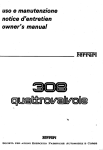
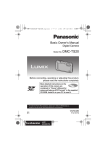
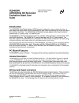
FIGURE 1: OUTLINE DIAGRAM
The "Turn-On Checkout Procedure" in this manual can be
used as an incoming inspection check to verify that the
supply is operational. See the appendix for tests that verify
the supply's specifications.
Options
The following factory installed options are available with
this instrument.
Option
0E3
0E9
Description
Input Power :
230 Vac 4^/10%, 47-63 Hz, Single Phase
Input Power :
100 Vac -^/-10%, 47-63 Hz, Single Phase
Location And Cooling
Figure 1 shows the outline shape and dimensions of the
unit. It is shipped ready for bench operation after connection to an ac power source. The supply is air cooled.
Sufficient space should be allotted so that a free flow of
cooling air can reach the rear of the instrument when it is in
operation. It should be used in an area where the ambient
temperature does not exceed 40 degrees C. The current
derates 1 % per degree C between 40°C-55°C.
Instrument Identification
Hewlett-Packard power supplies are identified by one serial
number. The letter "KR" designates Korea as the country of
manufacture, the first digit indicates the year ( 1 = 9 1 ,
2 = 92, etc), the second two digits indicate the week, and
the last five digits of the serial number are a different
sequential number assigned to each power supply.
Input Power Requirements
Depending on the line voltage option ordered, the supply is
ready to be operated from one of the power sources listed
in the Specification Table. The input voltage range, and the
input current ar>d power at high line voltage and full load is
listed for each option.
If the serial number on your instrument does not agree with
those on the title page of this manual, a yellow change
sheet may be included if a design change has affected the
contents of this manual.
Power Cord
INSTALLATION
This instrument is equipped with a three conductor power
cable. The third corKiuctor is the grourxl conductor and
when the cable is plugged into an appropriate receptacle,
the instrument is grour>ded. The offset pin on the power
cable three prong connector is the ground connection. In no
event should this instrument be operated without an
adequate cabinet ground connection.
Inspection
When you receive your power supply, inspect it for any
obvious damage that may have occurred during shipment.
If there is damage, notify the carrier and the nearest HP
Sales Office immediately. Warranty information is printed on
the inside front cover of this manual. Save the shipping
carton and packing materials in case the supply has to be
returned to Hewlett-Packard in the future. If you return the
supply for service, attach a tag identifying the owner and
model number. Also include a brief description of the
problem.
The power supply was shipped with a power cord for the
type of outlet used at your location. If the appropriate cord
was not included, contact your nearest HP Sales Office to
obtain the correct cord.
1-4
HEWLETT
PACKARD
E36WA
DC KMCtt SUrPLT
0-ew.M/o-nr.aA
. ON
]:
OFF
±
2«1 VDC MAX
TO
1
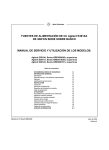
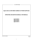
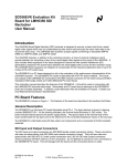
FIGURE 2: FRONT PANEL CONTROLS AND INDICATORS
Constant Current Operation
OPERATION
To set up a power supply for a constant current operation,
proceed as follows:
a.
Turn CURRENT control fully counter clockwise to
ensure that output decreases to 0 A, and then turn on
power supply.
b.
Adjust VOLTAGE controKno load connected) for
maximum output voltage allowable(voltage limit), as
determined by load cor>ditions. During actual operation, if a load change causes the voltage limit to be
exceeded, the power supply will automatically crossover to constant voltage operation at the preset
voltage limit and output current will drop proportionately.
c.
Adjust CURRENT control for desired output current
while depressing CC SET button(CC LED will not light
until the supply is loaded)
Turn-On Checkout Procedure
The following checkout procedure describes the use of the
front panel controls and indicators illustrated in Figure 2 arxJ
ensures that the supply is operational:
a.
Push LINE button to ON.
b.
Set RANGE push button to desired range.
c.
Turn VOLTAGE control fully counter clockwise to
ensure that output decreases to 0 Vdc then fully
clockwise to ensure that output voltage increases to
the maximum output voltage.
d.
While depressing CC SET push button, turn the
CURRENT control fully counter clockwise and then
fully clockwise to ensure that the current limit value
can be set from zero to maximum rated value.
e.
Connect load to output terminals.
Connecting Loads
The output of the supply is isolated from earth ground.
Either output terminal may be grounded or the output can
be floated up to 240 volts off grour>d.
WARNING
Each load should be connected to the power supply output
terminals using separate pairs of connecting wires. This will
minimize mutual coupling effects between loads and will
retain full advantage of the low output impedance of the
power supply. Each pair of connecting wires should be as
short as possible and twisted or shielded to reduce noise
pickupdf a shield is used, connect one end to the power
supply ground terminal and leave the other erxl unconnected.).
Shock Hazard
Disconnect ac power before making
output terminal connections.
Constant Voltage Operation
To set up a power supply for a constant voltage operation,
proceed as follows:
a.
Turn on power supply and adjust 10-turn VOLTAGE
control for desired output voltage(output terminals
open). CV LED should light.
b.
While depressing CC SET push button, adjust 10-turn
CURRENT control for maximum output current allowable (current limit). During actual operation, if a load
change causes the current limit to be exceeded, the
power supply will automatically crossover to constant
current mode artd output voltage will drop proportionately.
Operation Beyond Rated Output
The output controls can adjust the voltage or current to
values above(up to 5%) the rated output as indicated on the
front panel display. Although the supply can be operated in
the 5% overrange region without being damaged, it can not
be guaranteed to meet all of its performance specifications
in this region.
1-5
but will decrease the safety provided by the current limiting
circuit. A high-current pulse may damage load components
t>efore the average output current is large enough to cause
the current limiting circuit to operate.
Pulse Loading Consklerations
The power supply will automatically cross over from
constant-voltage to constant-current operation in response
to an increase(over the preset limit) in the output current.
Although the preset limit may be set higher than the
average output current, Ngh peak currents(a8 occur in pulse
loading) may exceed the preset current limit and cause
crossover to occur. If this crossover limiting is not desired,
set the preset limit for the peak requirement and not the
average.
Reverse Current Loading
Active loads connected to the power supply may actually
deliver a reverse current to the power supply during a
portion of its operating cycle. An external source can not be
allowed to pump current into the supply without loss of
regulation and possible darnage to the output capacitor. To
avoid these effects, it is necessary to preload the supply
with a dummy load resistor so that the power supply
delivers current through the entire operating cycle of the
load devices.
Capacitive Loads
An internal capacitor, across the output terminals of the
power supply, helps to supply high-current pulses of short
duration during constant voltage operation. Any capacitance
added externally will improve the pulse current capability.
1-6
Whn%
tati
HEWLETT
PACKARD
HP E361XA SOW DC S E ! 5 S 7 |
€ S % n ^ ^al n^^\
•
^n
^v^
HP E3610A, Seria Is KR20600101 -J -JL
HP £3611 A, Seria Is KR20600101 '^ Zl oV^
HP E36I2A, Soria Is KR20600101 -^i U-
s.
*^
oVx| 4Sj.
•1 -
2
°M^ 4^'-
2 2
2
2
2
2
2
:i
4
^H.a
4°J- '-!i -'"Hj
^|u!| ^l-o^V
V1V| B h I
xj^l
•-1
2 - 4
2 1
2 4
2 .1
2 .1
2 - 5
2 .5
2 .5
2 .S
2 .5
2 .5
2 6
2 6
2 6
A -1
^4
^1^1 '-^ ^o"4
°x^ ^i^J A-? ^^oi•li^J SLTz.
l-§^l-^^l ^d',! 11*1^J^i'\)--S~§^d^dfr ^-g•rsf °i^.
:^,H^ -t^ ^|-oHM-|5| ^-g^i---- '^sl-g-^c^^o^ -V-il
<M^Jfr -'^*F
3 . ^ T^el 4*0'-
ojill °rJ-4: 1992id 211
Manual Part No. 5959-5304
Microfiche Part No. 5959-5307
2 ]
a^Ol oj7^S ^^EHOllAi 7 p | L)|^o| g ^ ^x\
4-gr 4 4 ° ] 31^ M»\^ A^<H1 ^14°i '=>1^44•=•^ 1V4.
ofellsl -yiiV^-^-^J ° M ^i^A "rS] A).*„V_^- ol 7\7]S.] ^~%-,
oj-g 7 | 3 :
^1 ?i--^'?i, -v^ ^17|£| ^d^l, =slli ^ ^M-^o'-^l "J-^d i - t r
-?r ^Itt-^HI Si^K ^=fl»-H.H.AHr -•2.^-!i-i-''l -^-I^d ^T^ 4
^'•1-^- 4?l^l ?^-^ Jl^oHl c)llV syjoj^ :^l;^l ?s^i^cK
A
.4>'I iJ^<^_ 7 | i ; A|-§.47}. 7)4
"Hfr'^.-g- * 4 ^ ^ ^elil4 sa-l- "11 -^1
S S g ^ soil
"i^i^H °J-^4-i- «l-°.Rl-4.
: i r l c£i-
?l?l S^l
°1 ^ll^~gr -^.H! I -^-3- 44(-'iL^-§- ^^4 •^^44 ^I4=r)<^l
4. -d^l -1^.4^ *li5l-44 ^144 4 4 4^1 ^l- ?Dul-«-S-
nVARNII4c|
^J°l ^d4ii("^Fii ^d^l-ii)°ll H+'-d4 "^^^H <ii^ .S^Hs]
L^H AC 4 ^
y<Hl
° i ^ 5 H ° t t!-4. Ji5.(^d4) ^-^^44 l-f-5144 ^d4
'-^44 ^'^ysM. 4^.Hl7|) sH-i- vl^ ^ al-Sr 4 4 -5^4
o) ^K^o] o^7iEii4. 7|7i7|. sq-f°) 4:5- t!°^4-M- -f*M
4^-?r -i^S-ll-ttf'il, 4-^ '^U4 4 4 li-^H^ AC 4 ^
4 ( 4 ^ -:?-H^ -S-4)5^ 4 4 4 ( 4 4 s J 4tll)4 °.14-£l4°f
1V4.
^'^•145- ^! 4 ^ ^1°]^^
WARNING it-'.li- ^V^-g- s|"Kl4. 4^- ^*SilH4 ll-^ii|4. 4
=vh<Hli 5ll-^- ^|*J -1-^. °J-;;- 4 4 ,
^1-g-. i£-^- -P^^^1^ 44^ -^^^- -^sl
-^144. WARNING jL^-H| "^7]
Sl i4-H--S- 4-4*1 °l*1|4:i'- :i ^.
4-i-°ll -^'-^^J "Hvj-xi--- 4.g-A _^
4l^4.
CAUTION jL4-^ ?14-gr s|..|^i.
4. 4-;^- --r^m-']^ i - ^ 4 4 <I1-S4*11 si.^ 4-V-ii- -t!r4-^l?144 4
4 ^ ^ i °J^r -S-i- 4-4''|- 7°r44
4*<|- -y-g- -r^lAj^juK C.^UT10N
7hd^o^ 4 ^ ^ -fr4 ^ 4 4 ° J t -^'H)4t 44-S- 4-§-4
jtA|<H] 'g7li{! ;£4-|t-g- 2!--<i*| o|
silsKii a -^4-!i-<Hl -V-^H! "114^1
444^
4 4 i^j.-^R:- 4 4 •i--^7i7|- ,-<j:.5i^^{-^_o__^^^ A).
-§^^ "fl 4 4 4 ^ H ^ 4 4 - t til ^l-&-s|.ii, 44f- .i^iJ^Me
4 4 ^-^'•--'I^F 4 4 4 - 4 - ° - ^ 4-§-*! "fl - t 4 4^4 4'Jl-34 * f e <H1 4-§-Sl4. CC SET ^ f # 4-&°-5. - 3 r 4 ^ 4 4
^ 1 4 4 n y - . -^\Tf 3-J'P-yji. 4-W- 4-^l ^^-S- 4 4 * H 1 U
^jlh 4- 4 4 .
7iia
°1 -2-1- "^ :iz.4- ^ 4 4 * J 4 t E3610A, E3611A,
E3612A f-s| o]-?-- ^^\ (dual range) HP 4 4 -^S- 4
4-g- tHr-4. ^11 s-^i Ji-f- i!^ g^ 4 4 H } - ^ IC 5|s.<Hl
44-?r - i ^ * H r "^ll ^ * l •?r%-^ ± . ^ ^ \ % M ^ 4 4 ^-H'"
4 4 4 < H l t 4^-14 4 4 ^ 1 4 4Tl-^|7l- 4 4 . 3 1/2 4 ^ l . ' i
(E3611Ai:- 3 44J5-) 4 4 Jt^l 'H 3 4^lJ= 4-^1 .it^-l
•vr # 4 4 4 4 44f-K- "^4-4^1 44'-,iJ4. 4 i ' - 4 s | -5r
4 -^-^-Pr 4 4 -3^ #^o^it°fl ^ 4 ^ 1 4 4 4 .
4^1 -H.-1:- Mj-I-S- ^1 7 H _¥_c|o)| 4 ^_^-g-sitK 4 * l - t #
4 " ^ ^ l ^ ^144-4 RANGE -^r-i- tH-^-Hl ^ j s H 4'^J!4
4 . -t4-S- -S-4 "^^1 44°il 4*^ 4 4 'H ^ ^ ^ '^J-^-4
^j?_ 2 : 4 1 -r 114.
2-2
4°o'= ^A ^71- -e-^j
•^^ :
^^
11.5 Vac +/-\0%. 47-63 Hz, 0.8 A, 70 W
100 Vac +..-10"«. 47 63 Hz, 0.8 A. 70 W
230 Vac +/ 10?^,, 47-63 Hz, 0.4 A, 70 W
444<H1-;- 3^5] -p•^ sy-<M 4-7- {+) ff--fe (- ) 41-4
•;- 4 ^ 4 V.°A^H 4-5-4 4 4 4 ! 4 4 4-^^:14 ^H-4
^---t <5I4-.
: E3610 A : 0 ~ 8 V, 0 - 3 A, ;.•.•;=0-1.5 V. 0 - 2 A
E36II A : 0 - 2 0 V. 0 - 1 . 5 A. i'vl0 - 3 5 V, 0 - 0 . 8 5 A
E3612 A : 0 - 6 0 V, 0 - 0 . 5 A. t.'i-;0 - 1 2 0 V, 0 - 0 . 2 5 A
•
Voitt
Vo,
POUT MAX
30 Watts
" o f Hlss(|_Qacj Regulation) :
•^c!4°i:- -3''^ ^i-^'l- 0°IH 4-V-4 4 T F 4 ^ 1 4 4 " I I
(3.01% + 2 mV "14
•illjf
# 4 44'^1 OoflM 4r-1144 '!^4-"fl 0.01.';, •
i mA
%2
oiE^ 3 ° ^ ^-g-KLine Regulation) :
•'j<-14
4 4 4 4 '-H4 4 4 4-^<Hl -^Hsfl 0.01% .
2 mV "14
'iV.?r
4 4 4?1 ^ ^ \ 4 4 4-^'Hl ciiiij o.Ol ".. <
1 niA ° I 4
lo,
C«rmit
^ ° | : High C u r r e n t RANGE 4-g--^l '*l-c- --t.-i 4
rHl'H^:- 4 ' - 1 4 V()o.!i4 ^-t- # 4 ^5144 4-^-;r 4
-?-i 4'^K
E36I0A: ¥.'.45 V V.'^=8 V I.N^2 A Ii.^-3 A
E.3611A: V".-35 V V"--20 V I"i=0.85 A W^\.b A
E3612A: V";-.120 V V"-=60 V I"i-0. 25 A IN.=0. 5 A
e.|#(Ripple) ^ ^ s ( N o i s e ) :
--<j 4 4 - 200 /.N rm.s / 2 mV p p(10 Hz 10 MHz) "14
•y 4-n- - 200 iu.\ rms / I mA p-p(10 Hz-10 MHz)"l';V
^ £ a ? l : 4 4 #4<H1 ciisii ot;<Hl4 4 0 t ; 4 4 4-S-.
40t;°il4 5513 4 * H I 4 tl«l i - t 4 4^4 l'^^/4 4
--5-4.
^ n m ^ 510. n V
s^-14:°J/ ^E.3610A
g £ ?II4= :
-ij<l4 - iJ-^l r 4 0.02% + I mV "14
^j 4 f r - 'il'^1 r 4 - 0.02% + 2 mA "14
V-ir-
4 £ # & A] 7} :
4tll -V-*Hl-^-| 4'Li- -V--44^1, Jt-L- ll','!- -r4'H|4 ^i^H
.V-44-xlsi - t 4 4 f r 4 4 5 H I '^Hsfl 10 mV m 4 -S'4
sl-M- ^•r4-c- 50 usee ° I 4
E3611A
E3612A
E.3610A
E3611A
E.36I2A
100 mV
100 mV
10 nA
10 mA
I mA
Down Progrannming ^£E : -T-"-4 4tD'HI4 4 " ^ #
4 ^J4 44-5J---V-4 ^l-^H # 4 4 4 4°,l-4 0.1%4^1
4 ° l 4 - l r i - t s i s l - t * N -^1-4.
E.3610A : 3\t^ 2. , 5 i
E3611A : 4^1) l . O i
I so I at ion : +/- 240 Vdc
E:3612A : aUD
1..5i
S ^ °}S£(Output Drift) :
4 4 4 - H-i- 30-^r4 -^4^14 -f 8^-14 -^-4 4*fl '^-s*l7f 0.1% + 5 mV "!•;!:
^ol4J: - *l-g- 30^.-4 -^^-4^14 -f 8^14 - ^ 4 4*fl 4-^* r 4 0.1% ) 10 mA "I "J
5ll^^£ : 4°.!44 4 44.
E3610A: 1-14
E.3611A: 4°,h
E.3612A: 4 4
S^^l/S-#7|| g ^ £
Counts
^ 4 : -i^^o"44 4 - 8 - 4 4 .
: 25t; ±5t;<H|'^l + 0.5% .
I02
2
4 4-TT- -^-445. j f - - 4 ^ ^ 4 - t
10 mV 4 - ^ 5 mA
10 mV 4^?- 5 mA
100 mV 4 r r 2 mA
S^t : •-'14 ? - 4 8.4 lbs/3.8 kg, i 4
lbs/4. 2 kg
Hf^oj M S :
-§-4*14:- ^i^Afr s]j^{^ ^ ^ 4 4 ^ 1 ^l^d 44-g.- i ^ 4
ii€- 3)-V-4-R-s.-i-4 4 4 ^ ^ 7 ] i f i i t } 4 . 4 4 4 ?1
S-^ 44-tT- .^§-<H|4sl # 4 44-S- ^ ^ ' ^ ^ l
( T - 4 ) * --^71-48-^
2 ,3
4 i
^ f^4 9.3
m
m
m
° 1
'
•
i
!
1
]
& \
•
212.3 mm
8 354 in
s-^l
88.1 mm
3.469 in
2 6 9 2 mm
10.591 in
•
11 1
iil
318.4 mm
12.534 in
a U 1 : S\^E.
•;K iF-4, 4HI-4- -ic'll i i - 4 4 i l - -^-^iVcK
'•I 717]-;^ --i^-ij-cHjA-I ^,j*14 ° M ^ ] M ^ 4 4 ° 1 4-§--'Hb.-i "fl-T4ofl 4 t "^l-^-^l 4 4 4 4 " - L - 4 - ^ o ] ^ r ^ i
44.
4 - ^ 4 - 3 - 4 4 4 7 ] 4 4 - ^JA). S^-OJ^J^.^ Af^g-sj ^
4fi44
0E3
0E9
^
ojcf.
-V-^-<Hli:- 4 4 -i-H^7i Ai-oj:-^ 7jAi.$}. .-^ Oji^ iL^O) Ajej
iii:
°,14 4 4 :
2.30 Vac +/ 10%. 47-63 Hz 4 4
44 44:
100 Vac ./ 10%. 47-63 Hz 4 4
44.
.0.4 i-g- 7i7isi 4 4 - 5 ^ 4 ^6114 i i l 4 - # ^ - 4 - r i ! . 4 4 .
ol •/i7i-t j?.Tf 4 4 ' H l °A'^^\''A -n-4 -^l-S-^l-^sl-^-. -Ii
'll-g-S- -2--^U- -^^.i-sM, 7i7i7l- -s-i-sj all ^f4 ^-471-
7|7| 4 | o |
^JSi47l| 7l7)ol -^U^Oj!. £.c]7^ ^
^sJi^Ji4H ^ \ ^ - l H t ^ \ ^ 4"^,'- :.i-R-4- 4 4 4 . i - i t 4 ^
4 . 4 - ? r 4 "KR"-a- ^1|:t-i^o| ^V^-Q- jt.A|5).r^, .^.ii«i| ^-r
4 i < H | 4 •S-l-sl4<^t l t - 4 . 4 ^ 1 40'~50°<Hl4-b 1° ^-71^•Hl 4-^1- i%£| 4.^71- 4 4 4 4 .
4^r ^flj^- 4-t(l-91, 2=92 f-)i!- 44'-l|4, ti-g-4 -Y-'D
4 -t-7l-^ -t-(Wcek)-g- Lful-tUr^, ; z . E l i U--P-. up,! ^ ^ 4
.^ 7_}- 4^1 -i^-^7H] «Kj-3rl <ij?j t t i j L 0 l 4 .
°m S S a ^ Aitf
-r-i-4 4-^-!! 44'Hl t 4 4 , ^l-S-?r 44= '^ 4^Jitofl .^-/.i
717)21 4 4 4 i 7 i - .y- ^ r ^ 4 s l it4'Hl 4-!;^ 4 4 <i!-*14
4 ?^g- 4 - H : - 47l|4"-^-5-jiL 4 4
4 4 4 -44 TT 44-0114 -^-§-44. ^-t 4 4 ^4"Hit- 4
s<!-*-'|sl 44-S-"'-171- *d
4 4 4 ' 9 4 , 4 4 4 f r "J 44<^l ' ^ _ 4 4 4 .
-V-44.
S U S.E.
^i^l
"=-1 7 l 7 H | i r 3^1121 ^ ^4- E i 4 oj-b 4 4 i-^l-g-^l 4-Y-SI4
44.
SAl
'r-"r°] 4 - ^ r 4 ^ - 4 ^ 4 4 4 .
- ^ 4 4 -V-2-°l 4 4 4 .
44°I
^
'Sl'^l-lr 4 4
44
4*J-'Hl'^is. <^I 7l4-tr -S-§-sM4-tr
444.
-^1 - S - 4 4 4 4 .4'71-S- 44-fr^l!='-14-^^- 4 4 ••^14°i| 4 4 1 ' 4.
^11 411 - S - 4 4 ^ ^d^
^d4 •5-4Ei'=>H, ^lol-4-g- 4 4
t!- -t^ofl -S-S- "fl 4 7 ] ^ 4 ^ 1 4 4 . 4 4 4 ^^»M
4 4 -^i'-47|ii- - = ^ 4 4 "fl. -S-4!- 5L-f- 4 ^ S 4 - r - t 4 ^ ^4
OXS.-^ *..g-^V 3L7J-
ol if^o-jz^o): t ! - 4 . 7 l 7 l i - ^--^1 -g-5L7l- 40t;-g- 4 7 | °^{r
^fl-S- -•i-^^'Hl 411- 44-?r .4 " f l i r 4 £ l il^^l 44<H1 S.
4 4 - ^ ^ 7 H l t ^M-7f£l >^14°fl4 ^-l-g-^Rr ^ 4 - ^ 4
^
y ] ^ \ ° \ 4 4 . * M - . '11-g-^- 44*^=J]4-'=-oil • J H ^ ^ ^ ^
E)lo]i wv- ^ d ^ s j ^ l - 4-Y-S14 4 4 . 4-V-44 4 4 " i i ^
ofl t i i H l 4 4 i 4 - l 5 - S - - t 4 t } - 4 . 4 H 1 : ^ # 4 7 l ^ 1 4 4 ^1
4 4 4 ^ ^ ! 5^4-El 4 4 44<H1 4 4 * M 3 ^ - f r - 7 4 4 .
-g--^ 4 4 ^ * H e 4-°r, A-Pr^ 4 i'-'S 4 J : # it^.l*flo^ It2-4
HEWLETT
PACKARD
E3«I0A
OC POWER SUPPLY
e-«v.lA/o-i>«.n
• • • 1 1 ^
ADJUST
HMaBB
VOLTAOE
^ ^ ^
. ON
• OFF
CUWENT
OUTPUT
+
D::: a
±
ntl 2 : S^^^ iSXf
il
^ ^ ^
-
2U3 VDC MAX
J.
TO
X
SApl
•&-§-
A|£A| s a
-•'J4n=r ^"r-S-^ 4 * f l ^ i t 4-8-4 ^^Vo] ^VcR
a. -§-4 4^T-7l- 0 A7l- Hi51-^ 4 - ^ ^ 4 4 - 1 '^MMl 4*^=
Aju 4 4 4 =-4 ^ 4 4 - i - 471-4-4-.
b. -V-4-H1 4-4 4 ^ j 4 4-§-7l-^4 4-^4-21 - t ^ 4 4 ( 4
4 iMD-a- 4 4 -^471-s. i ^ J l t - 4 . 4^11 -S--g-o||4-t
-V-4 4-5--'^-^ 4 4 4 i 7 l - i 4 s l 4 , 4 4 -?-3-7l-;r
7H|--4^°_j?. 4 4 4 4 ^ J U i * 1 4 4 4 4 4 - ° ^ 44i^M, -i^4 4fp7l- -Y-*HI «l-4 7j-^iV4.
c. 44-^r - t 4 44f-S- ^|sll4t- CC SET 4-&-I- ¥ ^ 4
tll<HMl 4 r r i 4 7 l - 5 - ^ - ^ i 4 4 .
^4
ofBiisi 7j7j ;<44i^ ; L 4 2O1| ofl'-14 ^ M ^ \ i 4 4 'i^ i t
^l7l4 4-l-g- 4 4 4 4 ^11^4 -?r§- 4-4-ii- 1 ^ 4 4 4 .
a. LINE 4^-g- 0N°-5. -^--fr4.
b. RANGE -Sf-f- 4-1-r-S- 4-4-.:- 44'Hl 4 4 4 4 .
c. t4-g-.4-'t(0 Vdc)5- -fro]y] ^u-H'.-i-;-- 40]- i£^J.-44-
•^I'^l H M 4*<}=-'^-^- -M-4:.^- -N'^ -1r4 4 4 - ^ ' : - -J-^l^147| 4sfl4-;r ^-Hl 4*<J=-°-!- -v':-^!4.
4 - ^ IMI n t - 4--t(0 mA) -«--?, 3^21 :^l-i_sL 11--<j
4 n^ 4.£-^ CC SET n-^r 4^-S- ¥ ^ 41^11 "^l^l 4
•^ ^ 4 4 - g - ^ l i "^M 'y-4= -^-?.- ' - I i 'Sl-^ot-^^L -;i-4
4.
-Y-4-rt- # 4 440II 444-t;K
"5f ° i ^
4 4 -iT?-^14 #4-i«r =^^^14 -S-45M 4 4 . # 4 4 ^ H ^
•il42f 4 4 4 4 4-l-«h -1^^. 4--n. J^?r 4^r-5-i ' • H - ^
-r 4-5-4, °1 "fl4 M14°.^ (Isolation Voltage).;^ 240
Vdc4^1°14.
WARNING
4 4 ^114 -v-sl-s- oj--^.*}- ^•^-, 7^v -v-sl-sl 4 4 4 - i - ? r '4
-§-44 4 4 ij-ii^7i2| -i^B^ u(-7Hl 44^14*1= l t - 4 . <=>l«i^
^l 4--<^-i«1 4 -Y-4421 4 i 4-1-4 Ai'l-^l- 4 ^ 5 1 - 4 4
^d4 -^4 ^l'?!
^i^l
-^-H^7io|
uj..g. * 5 i
4 4 4 ^ s i
^j-=!j-g- ^ ^ - * i
i)ej
^-- 4 4 . 5!i4, 4 4 4 4 - 5 - f - 7I-0-4 4 r M ° \ 4 4 , 4
-g-f.- -^-<^l7l 4 4 4 -^^44 43114 (Shield Wire)-°- >•}•%4-;r 4°1 -?-i;l-(43114-1- 4 - i - ^ "fl-t 43114 ^ ^ ^ 4
••^14^ 4 4 44oii o,i^5i.j7_, ufs. •^v?£ ^f =y4 4-S- 4
4^1^14 ?*\.^ ^Hf-4-).
--<o^44 1-^-S- ^ l * f l 4 ^ 4 f r 4 4 4 4 4 .
a. 4 « K r % ^ 4 4 ( # 4 4 . 4 'fl4)-g- ?144 4 4 -?-i/71-S- 4 J I 4 4 -^47l-i- .i:<j-44. oiufl CV LEDofl
b. 7H5-4(4-^ 4711) 4 - ^ 4-fr ?l-S- 4^c!47l ^ M CC
SET -Y-S- 4^-S- ¥-2- 4tflo|14, 10-tmn 44i--=fc^J
4 1 - 2:4 ^1-4. 4^11 -?:-§-M, -V-4 4-S--^3L 4 4 4
4 f r 1H17)- ± 4 4 i 5|4, 4 4
'It- 44-Tf-4
.0^?. ^l-^4_<^-iil 4?!-i^l4 -3-4 44-,r -?-*Hl 4 4
4*fl44.
^ ^ #2^ o|^^oi|A^°| ^ g
-^4 i^-'-<J4-;:- 444-ofl i ^ l 4 ^^4^1 5% <^14 514^1
44-^14 4-Tf-ll- - t 4 ^ -^ 4 4 . 4 4 i ^ 7 i t - 5%4 A
4 4 4 4 ofl 4 -2-**l -^^s 4 ^ 1 4 . i.i4f 4 4 'iJ ^ 4 - 1 4 -f^-^^l^. 4-?-i?- .^-41!- T^-t- ^ 4 .
2 5
^ ± -^SW JlSi Am
4 4 ^ ^ 4 t # 4 4^7}. Af^ioti .*^:.js) ^v^i-g- ii.i-sV
4 . 4 4 4 4 o l l 4 44^4-°-S. 4-§- 4*J-^J4. 44oll
4 4 4 1M171- 4 * # 4 4rt--'i4 -^-HI 44=^ ^ 4 4
4. -S-?r 4 H 4^(=^:^ -^'-4^1 4^54)t- 44o|| 4 4
4 4 ^ iMl-g- 4-g- T^ 4-°-"i, ° H 4 4 ^ 4 - ° - ^ 4*J4 4 . <^lEl4- 43!-g- 4 4 4 ?^-5-4, 4 * 4 f r ii:°l 4
43.1 3l3 4Tr a - t :iz.4*M 4 4 4-7llf- 4 4 4 .
*J=44?1^14, 4 f r 'flit- :sl-?-'Hl 21-sM 'fl-i'^Mr 4^4
^114 -^-^-^r 4 4 ^ 1 4 4 . -v-4f- 4--'-i-?T 4 T I - '114 ^ i s .
71- .-§-4^ ^ 4-g- 4 i - ? - 4i?- # 4 4Tf7F •?'-!^_-4 H
7] x|o)l- -V-*).oll ^-AVA o,]«] - ojul.
e^S# ^ o j
4 ' 4 ^-3-71 oil o^^^si _^.t -Y-si--.-^-x}- .=f.7io| ojH.j,..
=^14 4 4 r r - i - ^ i ^ -?-^7Hi -y,^!^ -,<jcj.^j- - oj_o,^_
°144- 4 4 f r f e - 4 4
-i--3-44 '114 7|--- ^}^J_J^} - ^ 4
^-•^Jl-^-lofl ^-4-S- 4 4 T^ 4 4 . <^I44 44-S-g- ^1471
4 4 -?-3-7lsi ^ 4 471-4 4 4 4 Ml-f- •&^Jl4t 4 4
4 -^-g-4 5S--^ 4421 3 i 4 ^ 4--^-!- ^-^t?-*h ^ 47ll
4 4 . 2l-V-o11X^ ^ 7 1 - 4 -§-Bj:AJ - « 5 l . - 3^^- ^j
-B-4-S-
^l*fl4^r 4 4
-?-H'-7|7F - - - I - - f 4 o |
-§-4 -=^71 ^j-V-5!-
-S-4 4i44- 44«1- 4- ^-S".-^ ^-^44 4*0*- -V--4-3- 4 4
4-^- 7iol 4 i ! . - 4 4 .
2-6
Wlsn% H E W L E T T
%i'tlM P A C K A R D
TISCH-NETZGERATE DER SERIE HP E361XA 30W
BETRIEBS- UND SERVICE-ANLEITUNG FUR DIE MODELLE:
HP E3610A, Serie KR20600101 und hoher
HP E3611A, Serie KR20600101 und hoher
HP E3612A, Serie KR20600101 und hoher
Inhaltsverzeichnis
SICHERHEITSHINWEISE
ALLGEMEINES
GerStebeschreibung
Technische Daten und Kennlinle
Optionen
Geratekennung
INSTALLATION
Wareneingangsprijfung
Aufstellort
Versorgungsspannung
Netzkabel
BETRIEB
Einschaltprufung
Konstantspannungs-Betrieb
Konstantstrom-Betrieb
AnschluB von Lasten
Betrleb inn Grenzbereich
ImpulsfSrnnige Lasten
Kapazitive Lasten
Aktive Lasten
HERSTELLERBESCHEINIGUNG
SERVICE-INFORMATION
Anleitung Teilenummer 5959-5304
Mikrofiche Teilenummer 5959-6307
3-2
3-2
3-2
3-3
'3-4
3-4
3-4
3-4
3-4
3-4
3-4
3-5
3-5
3-5
3-5
3-5
3-6
3-6
3-6
3-6
3-6
A-1
Ausgabe: Februar 1992
3- 1
GehSuse nicht dffnen.
SICHERHEITSHINWEISE
Gerateabdeckungen diJrfen nicht v o m Bedienungspersonal
entfernt w e r d e n . Wartungs- und Reparaturarbeiten sind nur
qualifiziertem Service-Personal vorbehalten.
Die folgenden allgemeinen Sicherheitshinweise miissen
wahrend der Benutzung, der W a r t u n g sowie der Reparatur
dieses Gerates beachtet w e r d e n . Ein Nichtbefolgen dieser
Hinweise oder besonderer Warnungen in dieser Broschiire
verietzt Sicherheitsnormen auf d e n ' fiir dieses Gerat
vorgesehenen
Anwendungsgebieten.
Hewlett-Packard
iibernimmt keine V e r a n t w o r t u n g fiir Folgen, die aus der
Nichtbeachtung der Hinweise und Warnungen entstehen.
Sicherheits-Symbole
A
Geratesymbol: das Gerat ist mit
diesem S y m b o l versehen, w e n n die
Benutzung
der
Bedienungsanleitung n o t w e n d i g ist.
Vor dem Anschlie&en
Uberprufen Sie, ob die eingestellte Netzspannung am Gerat
mit Ihrer 6rtlichen Netzspannung ubereinstimmt.
Steht fiir Gehausemasse.
Gerat erden
HVARNINCJ
Dieses Produkt ist ein Gerat der Schutzklasse I
(ausgestattet m i t Schutzerde). Zur Verringerungder Gefahr
durch elektrisehe Schlage mu& das Gerategehause geerdet
und deshalb immer Ober ein dreiadriges Netzkabel mit
Schutzleiter betrieben w e r d e n . Beim Betreiben des Gerates
iiber einen Spartransformator ist sicherzustellen, daB der
Bezugspunkt des Spartransformators an den Neutralleiter
des Netzgerates angeschlossen ist (Gerat erden).
Das Zeichen W A R N U N G weist auf
eine Gefahr hin. Es bezieht sich auf
A r b e i t s w e i s e n , A n w e n d u n g e n o.a.,
die bei falscher A u s f i i h r u n g zu
Verietzungen des Bedieners fijhren
k o n n e n . Fahren Sie nur mit Ihrer
Arbeit fort, w e n n Sle den Sachverhalt und alle
erforderiichen
MaKnahmen verstanden haben.
Nicht in explosionsgefShrdeter Umgebung betreiben
Das Gerat sollte nicht in der Umgebung v o n leieht
entzijndbaren Gasen oder Dampfen betrieben w e r d e n .
Das Zeichen ACHTUNG w e i s t auf
eine Gefahr hin. Es bezieht sich auf
Bedienungsschritte
oder
Tatigkeiten, deren falsche A u s f u h r u n g
zu einer Beschadigung oder zur
Zerstorung des Netzgerates fiihren
k a n n . Fahren Sie nur dann mit Ihrer
Arbeit fort, w e n n Sie den Sachverhalt und alle
erforderiichen
MaBnahmen verstanden haben.
Der VOLTAGE-Regler auf der Frontplatte dient weiterhin zur
Festlegung des Spannungsgrenzwertes, w e n n das Netzgerat als Konstantstromquelle betrieben w i r d . Entsprechend
dient der CURRENT-Regler zur Einstellung des Stromgrenzwertes, w e n n das Netzgerat als Konstantspannungsquelle
betrieben w i r d . Mit Hilfe der CC SET-Taste laBt sich der
Stromgrenzwert einfach und bequem einsteUen, ohne die
Ausgange kurzschlieBen zu m u s s e n .
ALLGEMEINES
GerStebeschreibung
In dieser Bedienungs- und Serviceanleitung werden die drei
Netzgerate E 3 6 1 0 A , E 3 6 1 1 A und E 3 6 1 2 A beschrieben.
Diese Modelle sind k o m p a k t e Mehrzweck-Netzgerate fiir
den Einsatz a m MeBplatz. Sie eignen sich besonders zur
Versorgung von linearen und digitalen ICs in Entwicklungsumgebungen. Alle Informationen in dieser Anleitung
beziehen sich - w e n n nicht anders angegeben - auf alle drei
Modelle. Der g e w i j n s c h t e Ausgangsbereich kann durch die
RANGE-Taste auf der Frontplatte bestimmt werden.
Ausgangsspannung b z w . -strom lassen sich kontinuieriich
in beiden Bereichen einsteUen.
In der Frontplatte ist ein digitales Voltmeter/Amperemeter
untergebracht. Eine 3 1/2-Stellen- ( E 3 6 1 1 A 3-Stellen-)
Spannungsanzeige und eine 3-Stellen-Stromanzeige geben
genau die Ausgangsspannung und entsprechend den
Ausgangsstrom a n . Die Ausgangsdaten jedes Modells sind
in der Tabelle "Technische D a t e n " a u f g e f i i h r t .
3- 2
Technische Daten
EINGANGSDATEN:
AUSGANGSDATEN:
1 1 5 Vac ± 1 0 % , 4 7 - 6 3 Hz, 0 , 8 A , 7 0 W
1 0 0 Vac ± 1 0 % , 4 7 - 6 3 Hz, 0 , 8 A , 7 0 W
2 3 0 Vac ± 1 0 % , 4 7 - 6 3 Hz, 0 , 4 A , 7 0 W
E3610A:
0
0
E3611 A : 0
0
E3612A: 0
0
bis
bis
bis
bis
bis
bis
(einschlieBlich eines direkten Kurzschlusses a m Ausgang).
Die Ausgangsspannung w i r d i m Konstantstrombetrieb
durch die Konstantspannungs-Schaltung begrenzt.
8 V, 0 bis 3 A oder
15 V, 0 bis 2 A
2 0 V , 0 bis 1,5 A oder
3 5 V , 0 bis 0 , 8 5 A
6 0 V , 0 bis 0 , 5 A oder
1 2 0 V, 0 bis 0 , 2 5 A
•ANSCHLUSSE:
Auf der Frontplatte des Gerates stehen drei AnschluBbuchsen zur V e r f i i g u n g . Es kann jeweils der positive oder
der negative Pol m i t der Massebuchse verbunden w e r d e n .
•AUSGANQS-KENNLINIE
LASTREGELUNG:
Konstantspannung - Weniger als 0 , 0 1 % plus 2 m V bei
einem Wechsel v o n Vollast auf Nullast (bezogen auf
Strom).
ly
VoIH
V,
'01
POUT MAX
30 Watts
Konstantstrom
- Weniger als 0 , 0 1 % plus 1 m A bei
einem Wechsel v o n Null auf maximale Spannung.
V
'02
NETZREGELUNG:
Konstantspannung - Weniger als 0 , 0 1 % plus 2 m V bei jeder
Netzspannungsanderung innerhalb des zulassigen
Bereichs.
Konstantstrom
- Weniger als 0 , 0 1 % plus 1 m A bei jeder
Netzspannungsanderung innerhalb des zulassigen
Bereichs.
•
Carrcnt
WELLIGKEIT:
Konstantspannung - Weniger als 2 0 0 >yV (effektiv) und
2 m V (Spitze-Spitze) ( 1 0 Hz - 10 mHz)
Konstantstrom
- Weniger als 2 0 0 f j k (effektiv) und
1 m V (Spitze-Spitze) ( 1 0 Hz - 10 MHz)
HINWEIS: Ausgangsspannungen groBer als VQ^ sind moglich
bei geringem S t r o m , w e n n ein hoher Spannungsbereich
eingestellt i s t .
E3610A: v„, = 15 V V02 = 8 V lo,= 2 A loj = 3 A
E3611A: v„, = 35 V V02 = 20 V lo, = 0,85 A l02 = 1,5 A
E3612A: Vo, = 120 V Vo, = 6 0 V l o , = 0 , 2 5 A l02 = 0,5 1
TEMPERATUR-BEREICH: 0 bis 40°C bei Vollast. Stromabfall
von 1 % pro ' C zwischen 40°C und 55°C.
* A U F L 0 S U N G DER MESSANZEIGE
Spannu ng:
• TEMPERATUR-KOEFFIZIENT:
Konstantspannung - Weniger als 0 , 0 2 % plus 1 m V pro
Grad C.
Konstantstrom
- Weniger als 0 , 0 2 % plus 2 m A pro
Grad C.
Strom:
EINREGELZEIT:
Weniger als 5 0 p s bei einer Anderung v o n Vollast auf
Halblast (oder umgekehrt) und einer Ausgangsspannungsanderung v o n maximal 10 m V .
E3610A
E3611A
E3612A
E3610A
E36nA
E3612A
10 mV
100 mV
100 mV
10 mA
10 mA
1 mA
* A B W A R T S - P R 0 G R A M M I E R Z E I T : Maximale Zeit f u r die
Anderung der Ausgangsspannung v o n 1 0 0 % auf 0 , 1 % der
maximalen Nenn-Ausgangsspannung i m lastfreien Zustand
(NO LOAD).
ISOLATION: ± 2 4 0 Vdc
E 3 6 1 0 A : hochstens 2 , 5 s
E3611 A : hochstens 1,0 s
E 3 6 1 2 A : hochstens 1,5 s
•DRIFT:
Konstantspannung - Weniger als 0,1 % plus 5 m V Gesamtdrift iiber einen Zeitraum v o n 8 Stunden nach einer
Aufwarmzeit von 3 0 Minuten.
Konstantstrom
- Weniger als 0 , 1 % plus 10 m A Gesamtdrift iiber einen Zeitraum v o n 8 Stunden nach einer
Aufwarmzeit von 3 0 Minuten.
' A U F L d S U N G : Mindestanderung der Ausgangsspannung
Oder des Ausgangsstromes, die sich m i t d e m Gerat messen
laBt.
E 3 6 1 0 A : Spannung 1 0 m V S t r o m 5 m A
E3611 A : Spannung 10 m V
Strom 5 mA
E 3 6 1 2 A : Spannung 1 0 0 m V S t r o m 2 m A
QENAUIGKDT DER MESSANZEIGE:
± 0 , 5 % + 2 Ziffern bei 2 5 ° C ± 5 ° C
K O H L U N G : KonvektionskiJhIung
*UBERLAST8CHUTZ:
GEWICHT: 3 , 8 k g ; 4 , 2 k g verpackt
Das NetzgerSt w i r d permanent durch eine Konstantstromquellen-Schaltung gegen jegliche Oberiastung gaschutzt
(HINWEIS) • E R G A N Z E N D E
3 -3
KENNDATEN
212.3 mm
8 354 in
88 1 mm
269.2 mm
10 591 in
3.469 in
1111 ill il 111 ill
ill ill iill iil
•
318 4 mm
12.534 in
ABBILDUNG 1: G E R A T E A B M E S S U N G E N
Die "Einschaltpriifung" auf der folgenden Seite kann im
Rahmen der Wareneingangsprufung angewendet w e r d e n .
Das (separat zu beziehende) Service-Manual beschreibt
Testprozeduren, mit denen die Spezifikationen des
Netzgerates iiberprijft w e r d e n k o n n e n . Siehe bitte die
Bellage fiir Testprozeduren, mit denen die technlschen
Daten des Netzgerates iiberpriift w e r d e n k o n n e n .
Optionen
Die folgenden Optionen sind ab Werk mit diesem Gerat
erhaltlich:
Option
0E3
0E9
Beschreibung
Netzspannung:
2 3 0 Vac + l - ^ 0 % , 4 7 - 6 3 Hz, Single Phase
Netzspannung:
100 Vac -i-/-10%, 4 7 - 6 3 Hz, Single Phase
Aufstellort
Abbildung 1 zeigt die Abmessungen des Netzgerates. Es
wird betriebsbereit ausgeliefert und braucht nur noch an
das Netz angeschlossen zu w e r d e n . Das Gerat ist
konvektionsgekiihit und sollte deshalb ausreichend beluftet
w e r d e n . Speziell die Kijhirippen auf der Geraterijckseite
diirfen im
Betrieb
nicht
abgedeckt
werden.
Die
Umgebungstemperatur darf 4 0 " C nicht ilberschreiten.
Stromabfall von 1 % pro ° C zwischen 4 0 ' ' C und 5 5 ° C .
Geratekennung
Die Netzgerate von Hewlett-Packard tragen eine Seriennummer. Die Buchstaben "KR" stehen fiir das Fertigungsland Korea. Die erste Ziffer steht fiir das Jahr (1 = 9 1 ,
2 = 9 2 usw.) und die beiden folgenden Ziffern geben die
Woche an. Die letzten fiinf Ziffern der Seriennummer bilden
die fiir jedes Neztgerat verschiedene fortlaufende Nummer.
Versorgungsspannung
Stimmt die Seriennummer auf Ihrem Netzgerat nicht mit der
auf der Titelseite dieser Anleitung ijberein, so ist ein gelbes
Anderungsblatt eingelegt, w e n n eine konstruktive Anderung
den Inhalt dieser Anleitung betrifft.
Entsprechend der bestellten Netzspannungsoption ist das
Gerat bereit zum Betrieb an einer der in der. Tabelle
"Technische D a t e n " aufgefiihrten Netzspannungen. Die
Eingangswerte sind fiir jede Option aufgefiihrt.
INSTALLATION
Netzkabel
Das Gerat ist mit einem dreiadrigen Netzkabel (mit Schutzleiter) ausgestattet. Im Betrieb ist darauf zu achten, daB der
Schutzleiter niemals unterbrochen w i r d . (z.B. durch Einfiigen eines Veriangerungskabels ohne Schutzleiter).
Wareneingangsprufung
Bitte untersuchen Sie nach Erhalt Ihr Netzgerat auf etwaige
Transportschaden. Falls Sehaden festzustellen sind, so
benachrichtigen Sie sofort den Spediteur sowie Ihre
zustandige HP-Geschaftsstelle. Verwahren Sie den Karton
und das Verpackungsmaterial fiir einen eventuellen
spateren Versand an Hewlett-Packard auf. Wenn Sie das
Gerat einsenden, so versehen Sie es bitte mit einem
Anhanger, auf d e m Ihr Name, die Geratenummer und eine
Fehlerbeschreibung angegeben ist.
Das Netzgerat wurde mit einem fur Ihr Land passenden
Netzkabel ausgeliefert. Sollten Sie ein falsches Netzkabel
erhalten haben, so wenden Sie sich bitte an Ihre zustandige
HP-Geschaftsstelle.
3-4
r
HEWUETT
PACKARD
E3«tOA
DC POWER SUPPLY
• :.
0-SV,a*/0-injA
. 2A
3A
i
2<0 VDC MAX
TO
±
ABBILDUNG 2: FRONTPLATTE MIT REGLERN UND ANZEIGEN
M a x i m u m . W e n n nun wahrend des Betriebs eine
Oberiastung
auftritt
(der S t r o m g r e n z w e r t
also
iiberschritten w i r d ) , schaltet das Gerat automatisch in
den Konstantstrombetrieb, w o b e i die Ausgangsspannung proportional zurijckgeregelt w i r d .
BETRIEB
Enschaltprijfung
In den nachfolgenden Einschaltpriifung wird der Gebrauch
der Regler und Anzeigen - wie in Abbildung 2 gezeigt beschrieben. Gleichzeitig konnen Sie die Funktionsfahigkeit
Ihres Netzgerates (iberprijfen. Nachdem das Gerat mit d e m
Stromnetz verbunden w o r d e n ist, fiihren Sie bitte folgende
Schritte aus:
a.
b.
c.
d.
e.
Konstantstrom-Betrieb
Das Netzgerat wird wie folgt fiir d e n Konstantstrom-Betrieb
eingestellt:
a.
Drehen Sie den Stromregler (CURRENT) in den
Linksanschlag, so daB der A u s g a n g s s t r o m auf 0 A
eingestellt ist. Nun schalten Sie das Netzgerat ein.
Driicken Sie den Netzschalter (LINE) in die Position
ON.
Bringen Sie die Bereichstaste (RANGE) in die
g e w i j n s c h t e Stellung.
Drehen Sie den Spannungsregler (VOLTAGE) in den
Linkssanschlag urKi beobachten Sie dabei, wie die
Spannungsanzeige auf 0 Vdc sinkt. Drehen Sie nun
den Spannungsregler in den Rechtsanschlag bis zum
M a x i m u m der Ausgangsspannung.
Driicken Sie die CC SET-Taste, und drehen Sie
gleichzeitig
den
Stromregler
(CURRENT)
zum
Linksanschlag und anschlleBend zum Rechtsanschlag.
Der S t r o m g r e n z w e r t muB sich v o n 0 A bis zum
maximalen Nennwert einsteUen lassen.
SchlieBen Sie eine Last an Ihr Netzgerat a n .
b.
Stellen
Sie
den
Spannungsregler
(VOLTAGE)
(Netzgerat ohne Last) auf das zulassige M a x i m u m
(Spannungsgrenzwert),
wie
durch
die
Lastbedingungen vorgegeben. W e n n nun wahrend des
Betriebs infolge Lasteinderung eine Spannungsiiberhohung eintritt, schaltet das Gerat automatisch
bei Uberschreiten des eingestellten Spannungsgrenzwertes in den Konstantspannungs-Betrieb. Der
Ausgangsstrom wird proportional zurijckgeregelt.
c.
Driicken Sie die CC SET-Taste und stellen Sie den
Stromregler (CURRENT) auf den
erforderiichen
Ausgangsstrom ein. (Die CC-LED leuchtet erst nach
AnschluB der Last.)
AnschluK von Lasten
WARNUNG
Die Ausgangsbuchsen des Netzgerates sind v o m Gehause
entkoppelt. Jede Ausgangsbuchse kann geerdet w e r d e n ,
oder der Ausgang kann erdfrei bis zu 2 4 0 V betrieben
werden.
Stromschlaggefahr
Schalten Sie vor d e m AnschlieBen einer Last das
Netzgerat sus.
Es wird empfohlen, jede Last iiber eigene AnsehluBleitungen zu verbinden. Dadurch w e r d e n gegenseitige
Kopplungseffekte z w i s c h e n den einzelnen Lasten reduziert,
und die niedrige Ausgangsimpedanz des Netzgerates bleibt
voll erhalten. Die Verbindungskabel sollten mdglichst kurz
und verdrillt oder abgesehirmt sein, u m Storungen zu
unterdrijeken. (Falls eine A b s e h i r m u n g v e r w e n d e t w i r d , so
verbinden Sie ein Ende m i t d e m MasseanschluB des
Netzgerates und lassen das andere Ende offen.)
Konstantspannungs-Be'.. leb
Das Netzgerat wird wie folgt fiir den KonstantspannungsBetrieb eingestellt:
a.
Schalten Sie das Netzgerat ein, und stellen Sie die
g e w i i n s c h t e Ausgangsspannung (ohne Last) mit Hilfe
des 10-Gang-Spannungsreglers (VOLTAGE) ein. Die
entspreehende LED (CV) sollte leuchten.
b.
Drucken Sie die CC SET-Taste, und stellen Sie
gleichzeitig den 10-Gang-Stromregler (CURRENT) auf
3-5
}
Betrleb im Grenzbereich
Kapazitive Lasten
Das Netzgerat kann problemlos bis zu 5% oberhalb der
spezifizierten Ausgangsspannung (-strom) eingestellt und
betrieben werden. In diesem "Oberbereich" konnen jedoch
moglicherweise einzelne Spezifikationen nicht mehr
eingehalten werden.
Ein interner Ausgangskor>densator unterstutzt
die
Stromabgabe bei kurzzeitigen Stromimpulsen im
Konstantspannungsbetrieb. Jede zusdtzliche Kapazitat am
Ausgang verbessert zwar das Stromverhaltan, verschlechtert jedoch das
Begrenzungsverhalten der
Konstantstromschaltung. So kann beispielsweise ein
Stromimpuls eine angeschlossene Last beschadigen bevor
der mittlere Ausgangsstrom erreicht ist und die Strombegrenzung wirksam wird.
Impulsfdrmige Lasten
Bei einem Anstieg des Ausgangsstromes (oberhalb des
eingestellten Grenzwertes) schaltet das Netzgerat
automatisch vom Konstantspannungsbetrieb in den
Konstantstrombetrieb. Obwohl der eingestellte Grenzwert
hoher liegen kann als der mittlere Ausgangsstrom, konnen
Stromspitzen (wie sie bei impulsformigen Lasten auftreten)
den eingestellten Stromgrenzwert iiberschreiten und ein
Umschalten in den Konstantstrombetrieb bewirken. Falls
dieses Umschalten unerwiinscht ist, sollte der
Stromgrenzwert auf den mogliehen Stromspitzenwert
eingestellt werden.
Aktive Lasten
Angeschlossene aktive Lasten k6nnen das Netzgerat
kurzzeitig mit einem Rilckstrom beaufschlagen. Wird
beispielsweise durch einen externen Generator Strom in das
Netzgerat eingespeist, so konnen die Regeleigensehaften
des Netzgerates beeintrachtigt und der Ausgangskondensator besehddigt werden. Um dies zu vermeiden,
muB das Netzgerat mit einem Lastwiderstand versehen
werden, damit das Netzgerat permanent Strom abgeben
kann.
HERSTELLERBESCHEINIGUNG
Hiermit wird bescheinigt, daB die Gerate HP E3610A, HP E3611A oder HP E3612A
in Ubereinstlmmung mit den Bestlmmungen von Postverfugung 1046/84 funkentstOrt sind.
Der Deutschen Bundespost wurde das Inverkehrbringen dieses Gerates angezeigt
und die Berechtigung zur UberprOfung der Serie auf Einhaltung der Bestlmmungen
eingeraumt.
Wird das Gerat innerhalb einer Aniage betrieben:
_
So muB bei Inanspruchnahme der Allgemeinen Genehmigung FTZ 1046/84 die
gesamte Aniage der oben genannten Genehmigung entspreehen.
_
Die mit einer FTZ-Serienprufnummer gekennzeichnet ist, und fiir die eine
Betriebsgenehmigung voriiegt oder beantragt wird, so sind in der Regel keine
weiteren Schritte notwendig.
3-6
Whn% HEWLETT
mULM PACKARD
ALIMENTATIONS EN COURANT CONTINU 30 W
DE LABORATOIRE, SERIES HP E361XA
MANUEL D'UTILISATION ET DE MAINTENANCE
POUR LES MODELES :
HP E3610A, Series KR20600101 et au-dessus
HP E3611A, Series KR20600101 et au-dessus
HP E3612A, Series KR20600101 et au-dessus
Sommaire
REGLES DE SECURITE
GENERALITES
Description
Specifications et caracteristiques
Options
Identification des appareils
INSTALLATION
Inspection
Emplacement et ventilation
Tension secteur
Cordon d'alimentation
UTILISATION
Procedure de verification a la mise sous tension
Mode de tension constante
Mode de courant constant
Connexion de charges
Fonctionnement au-delii des valeurs de sortie pr6vues
Fonctionnement sur charges impulsives
Charges capacitives
Charges a courant inverse
MAINTENANCE
4-1
4-2
4-2
4-3
4-4
4-4
4-4
4-4
4-4
4-4
4-4
4-5
4-5
4-5
4-5
4-5
4-6
4-6
4-6
4-6
A-1
Imprim^ en Fivrler 1992
Reference Manuel No. 5959-5304
Reference MIcronche No. 5959-5307
4-1
REGLES DE SECURITE
Ne p a s t o u c h e r les c i r c u K s s o u s t e n s i o n .
L'utiljsateur ne doit pas demonter les capots de l'appareil. Le
remplacement des composants et les reglages internes
doivent etre effectues par un personnel qualifie.
Les r ^ l e s de s6curit6 suivantes doivent dtre observ^es
pendant toutes les phases d'Utilisation, de maintenance et de
reparation de cet appareil. Le non-respect de ces regies ou
des avertissements sp6cifiques Indus k divers endroits de ce
manuel constitue une infraction auK normes de s^curit^
applicables A la conception, ct la fabrication et d I'usage pr^vu
de cet appareil. Dans'ce cas, Hewlett-Packard d^line toute
responsabilitd.
S y m b o l e s de s ^ c u r l t d
A
Avant la mise sous tension
Symbole de renvoi au manuel ; ce
symbole indique que I'utilisateur doit
se reterer au manuel.
Indique une borne de mise ^ la
terre.
Verifiez que I'appcireil est rdgl^ sur la tension secteur
appropriee.
Misa d la terre de i'appareil
iwARNINcJ
Cet appareil appartient i la Classe de seeurite I (muni d'une
borne de ten'e de protection). Pour r^duire au minimum les
risques de choc eiectrique, le chassis et le coffret de l'appareil
doivent etre relies ci une terre eiectrique. L'appareil doit etre
connecte au secteur par un c ^ I e d'alimentation d trois
conducteurs, le troisieme assurant la liaison avec une terre
eiectrique au niveau de la prise d'alimentation.' Toute
intemjption de ce conducteur de mise ci la. masse^ ou
deconnexion de la borne de terre de protection, engendrerait
un risque de choc eiectrique pouvant entrainer des
dommages corporels. Si l'appareil doit etre alimente par
I'intermediaire d'un autotransformateur devolteur externe,
assurez-vous que la borne commune de ce dernier est
connectee ci la ligne neutre (borne reliee ci la terre) du
secteur.
Ce signe indique un risque. II attire
I'attention sur une procedure, une
manipulation, etc. qui, si elle n'est
Pels correctement executee, peut
entrainer des dommages corporels.
Ne pjursuivez pas au-delei de ce
signe tant que les conditions
indiquees ne sont pas entierement
comprises et remplies.
Ce signe indique up risque. II attire
I'attention sur une procedure
d'Utilisation, une manipulation, etc.
qui, si elle n'est pas correctement
executee, peut entrainer la
deterioratk>n ou la destruction
partielle ou totale de l'appareil. Ne
poursuivez pas au-delit de ce signe
tcint que les conditions indiquees ne
sont pas entierement comprises et
remplies.
Ne pas utiliser dans une atmosphere explosive
Ne pas utiliser l'appareil en presence de gaz ou de fumees
inflammables.
Le bouton VOLTAGE de la face avant permet de fixer la limite
de tension lorsque I'alimentation est utilisee comme une
source de courcint constant, et le bouton CURRENT permet
de fixer la limite de courant en sortie lorsque I'alimentation est
utilisee comme une source de tension constante. La touche
CC SET pennet'de fixer la limite de courant que l'on souhaite
utiliser, k I'aide du bouton CURRENT, sans avoir k courtcircuiter la sortie.
GENERALITES
Description
Ce manuel d'Utilisation et de maintenance decrit trois
alimentations HP i deux gammes, les E3610A, E3611A, and
E3612A. II s'agit d'alimentations de laboratoire k usage
general, particulierement utiles pour alimenter des circuits
integres experimentaux, aussi bien lineaires que numeriques.
Sauf indicatk)n du contrctire, toutes les informations fournies
dans ce manuel s'appliquent aux trois modeies. La gamme de
sortie voulue est seiectionnee k I'aide de la touche RANGE
de la face avant. La tension et I'intensite peuvent etre regiees
en continu sur I'integralite des deux gammes de sortie.
La face avant comprend un voltmetre/amperemetre
numerique. Un affichage de 3 1/2 chiffres (3 chiffres sur le
modeie E3611A) indique avec precision la tension et le
courant de sortie. Les valeurs de sortie prevues pour chaque
modeie sont indiquees dans le taibleau des specifications.
4-2
Specifications et caracteristiques suppiementaires
ENTREE
115 Vca •f/-10%, 47 4 63 Hz, 0,8A, 70 W
100 Vca +/-10%, 47 i 63 Hz, 0,8A, 70 W
230 Vca +/-10%, 47 d 63 Hz, 0,4A, 70 W
SORTIE; E3610A: 0 k B M , 0 k 3 f i , o u 0 k ^ 5 W , Q k 2 ^
E3611A : 0 d 20 V, 0 ^ 1,5 A ou 0 ^ 35 V,
0 d 0,85 A
E3612A : 0 4 60 V, 0 S 0,5 A ou 0 d 120 V,
0 k 0,25 A
•BORNES DE SORTIE:
La face avant comprend trois bomes de sortie qui sont isoiees
du chassis. La borne positive ou negative peut etre connectee
k la bome de masse.
•CARACTERISTIQUES DE SORTIE
A
•olta
REGULATION PAR RAPPORT A LA CHARGE :
Tension constante - < 0,01% + 2 mV pour une variation
comprise entre la pleine charge et la charge nulle du courant
de sortie.
Courant constant - < 0,01% + 1 mA pour une variation
comprise entre 0 et le maximum de la tension de sortie.
Vol
f'soRneM'^
30 Watts
y)2
REGULATION PAR RAPPORT A LA TENSION SECTEUR :
Tension constante - < 0,01% + 2 mV pour toute variation de la
tension secteur dans les limites des valeurs d'entr6e prevues.
Courant constant - < 0,01% -e 1 mA pour toute variation de la
tension secteur dans les limites des valeurs d'entree prevues.
•
loi
l02
Couruit
REMARQUE : Des tensions de sortie superieures k \ l „ sont
possibles k fable intensite lorsque la gamme de courant haute
est seiectionnee.
E3610A : Vo, = 15 V V „ = 8 V l „ = 2 A loj = 3 A
E361 IA : Vo, = 35 V Voj = 20 V I,, = 0,85 A I,, = 1,5 A
E3612A : Vo, = 120 V Vo, = 60 V lo, = 0,25 A l<„ = 0,5 A
ONDULATION ET BRUIT :
Tension constante - < 200 uV eff. et 2 mV crete k Crete (10 Hz
k 10 MHz).
Courant constant - < 200 uV eff. et 1 mA crete k crete (10 Hz
k 10 MHz).
PLAGE DE TEMPERATURE : 0 k 40°C pour toutes les valeurs
de sortie prevues. Reduction de 1% par °C du courant prevu,
entre 40°C et 55°C
•RESOLUTION DE
Tension: E3610A
E3611A
E3612A
Courant: E3610A
E3611A
E3612A
•COEFFICIENT DE TEMPERATURE :
Tension constante - < 0,02% -t- 1 mV par °C.
Courant constant - < 0,02% -f 2 mA par °C.
TEMPS DE REPONSE TRANSITOIRE :
LAFRCHAGE ;
10 mV
100 mV
100 mV
10 mA
10 mA
1 mA
•VITESSE DE PROGRAMMATION DESCENDANTE : Temps
maximal pour que la tension de sorbe passe de 100% ii 0,1%
de la valeur de sortie maximctle prevue, EN L'ABSENCE DE
CHARGE.
E3610A : 2,5 s maximum
E3611A : 1,0 s maximum
E3612A : 1,5 s maximum
< 50 usee, pour le retablissement de la sortie a 10 mV
maximum apres une variation de pleine charge ci demi-charge
du courant de sortie, ou vice-versa.
ISOLATION: ± 240 Vcc
•DERIVE DE LA SORTIE :
Tension constante - Derive totale < 0,1% -i- 5 mV apr6s 8
heures, avec un temps de prechauffage initial de 30 minutes.
Courant constant - Derive totale < k 0.1% + 10 mA apres 8
heures, avec un temps de prechauffage initial de 30 minutes.
•RESOLUTION : Variation minimale de courant ou de tension
de sortie pouvant etre obtenue ei I'ciide des commandes de la
face aveint.
E3610A : Tension 10 mV Courant 5 mA
E361 IA : Tensksn 10 mV Courant 5 mA
E3612A : Tension 100 mV Courant 2 mA
PRECISION DE L'AFFICHAGE ; ±0.5%+2 oomptes k 25°C±5°C
REFROIDISSEMENT : Par convection.
•PROTECTION CONTRE LES SURCHARGES :
Un circuit k courant content, aetif en permanence, protege
I'alimentation contre toutes les surcharges et contre un courtcircuit direct place aux homes. Ce circuit limite la tension de
sortie en fonctionnement k courant constant.
POIDS : 3,8 Kg net, 4.2 Kg embalie.
(REMARQUE) * CARACTERISTIQUES SUPPLEMENTAIRES
4-3
111
m
m
m
m\
212.3 mm
8 354 in
88.1 mm
3.469 in
269 2 mm
10.591 in
\—l
illilllilH^^^
I i i li li 1 ii
B
318 4 mm
12.534 in
FIGURE 1 : DIMENSIONS
Options
Pour verifier que I'alimentation est operationnelle, vous
pouvez executer la 'Procedure de verification k la mise sous
tension' decrite plus loin. L'annexe de ce manuel decrit des
tests permettant de verifier les specifications de l'appareil.
Les options disponibles avec cet appareil (instaliees en usine)
sont les suivantes :
Option
Description
OE3
Tension secteur:
230 Vca +/-10%, 47 4 63 Hz, Monophase
OE9
Tension secteur:
100 Vca -f/-10%, 47 i 63 Hz, Monophase
Emplacement et ventilation
La Figure 1 indique les formes et les dimensions de votre
alimentation. Celle-ci est livree prete k fonctionner en
laboratoire des sa connexion ei une prise secteur. Cet appareil
etant refroidi par ar, prevoyez suffisamment de place pour
que I'air puisse librement drculer k I'arriere pendant le
fonctionnement. La temperature ambiante ne doit pas
depasser 40°C. Le courant decroit de 1% par degre C entre
40 et 50°C.
Identification des appareils
Les alimentations Hewlett-Packard sont identifiees par un
numero de serie unique. Les lettres 'KR' indlquent que le
pays de fabrication est la Coree, le premier chiffre indique
I'annee (1 =. 91, 2 = 92, etc.), les deux chiffres suivants
indiquent la semaine et les cinq demiers chiffres sont un
numero sequentiel affecte k chaque alimentation.
T e n s i o n secteur
Selon I'option specifiee ci la commande, l'appareil est pret k
fonctionner sur I'une des tensions secteur indiquees dans le
tableau des spedfications. La gamme de tension, ainsi que le
courant et la consommation pour la tension secteur maximeile
et a pleine charge, sont indiques pour chaque option.
Si le numero de serie de votre appareil ne con-espond pas k
ceux qui figurent sur la page de titre, et si un changement de
conception a modifie le contenu de ce manuel, celui-ci doit
normalement inclure une fiche de modification jaune.
Cordon d'alimentation
INSTALLATION
Cet appareil est dote d'un cordon d'alimentation k trois
conducteurs. Le 3eme conducteur est le conducteur de terre
et, lorsque le cordon est branche sur une prise appropriee,
rinsbument est relie k la terre. Sur le connecteur k trois
broches du cordon d'alimentation, la broche du milieu est la
bome de mise k la terre. Cet appareil ne doit pas etre utilise
sans etre correctement relie k la terre.
Inspection
Lorsque vous recevez votre alimentation, inspectez-la pour
determiner si elle a subi des dommages evidents pendant le
transport. Si oui, avisez immediatement le transporteur et
votre bureau commercial HP. Les conditions de garantie sont
Imprimees au verso de la couverture de ce manuel.
Conservez le carton d'expedition et les materiaux d'emballage
pour le cas ou vous auriez k retourner votre eUimentation k
HP pour reparation. Dans cette eventualite, fixez une etiquette
identifiant le proprietaire et le n° de modeie. Joignez
egalement une breve description du probleme.
Votre alimentation eiectrique doit normalement etre livree
avec un cordon d'alimentation adapte au type de prise utilise
dans votre pays. Si ce n'est pas le cas, demeindez un autre
cordon k votre bureau commercial HP.
4-4
f
ESetOA
0 0 POWBR SUFn.Y
o-8v,aA/o-nv,aA
ADJUST
• ::.
2A
3A
±
2«1 VDC MAX
TO
X
FIGURE 2 : COMMANDES ET INDICATEURS DE LA FACE AVANT
changement de charge provoque un depassement de cette
limite, rallmentation passe automatiquement du mode tension
constante EUJ mode courant constant et la tension de sortie
chute en proportion.
UTILISATION
Procedure de verification d la mise sous tension
La procedure suivante decrit rutilisatlon des commandes et
Indicateurs de la face avant, representes k la Figure 2, et
permet de verifier que I 'alimentation fonctionne correctement:
a
Appuyez sur la touche UNE (position ON).
Appuyez sur la touche FIANGE pour la gamme voulue.
b.
Tournez le bouton VOLTAGE k fond dans le sens
inverse des aiguilles d'une montre pour verifier que la
sortie est nulle, puis k fond dans I'autre sens, pour
verifier que la tension de sortie augmente k la valeur
maximale.
Tout en maintenant la touche CC SET enfonc6e,
tournez le bouton CURRENT k fond dans le sens
inverse des aiguilles d'une montre, puis k fond dans
I'autre sens, pour verifier que la limite de courant peut
etre regiee entre zero et la valeur maximale prevue.
(Donnectez une charge aux bomea de sortie.
Mode de courant constant
Pour configurer une alimentation de fagon k seiectionner une
sortie k courant constant:
a
Toumez le bouton CURRENT k fond dans le sens des
aiguilles d'une montre pour verifier que la sortie Inverse
est nulle, puis mettez I'alimentation sous tension.
b.
Reglez le bouton VOLTAGE (setns charge connectee)
sur la limite de tension de sortie, determinee par les
conditions de charge. Dans des conditions de
fonctionnement reelles, sl un changement de charge
provoque un depassement de cette limite, rallmentation
passe automatiquement au fonctionnement k tension
constEuite, k la limite de tension preregiee, et le courant
de sortie chute en proportion.
c.
Reglez le bouton CURRENT sur le courant de sortie
voulu tout en maintenant la touche 0 0 SET enfoncee
(I'indicateur 0 0 ne s'allumera que lorsque rallmentation
sera chargee).
DANGER
Connexion de charges
La sortie de rallmentation est isol6e de la terre. L'une ou
i'autre des deux bomes de sortie peut dtre reliee k la masse,
ou la sortie peut flotter jusqu'^ 240 vdts par rapport e la terre.
Risque de choc eiectrique
Debranchez rapparell Eivant de connecter
une charge aux bomes de sortie.
Ohaque chetrge dott etre connectee aux bomes de sortie de
I'alimentation k I'aide de pai res de file de connexion disti notes.
Oecl reduit au minimum les effets de couplage mutuel entre
les charges et permet d'exploiter au mieux la feilble
impedance de sortie de l'appareil. Chaque paire de file de
connexion doit etre aussi courte que possible, et torsadee ou
blindee afin de reduire le bruit. (Si les fils sont bllndes,
connectez une extremite k la bome de masse de
rallmentation et lalssez I'autre extremite libre.)
Mode de tension constante
Pour configurer une alimentation de fagon k seiectionner une
sortie k tension constante :
a
Mettez rallmentation sous tension et reglez le bouton
VOLTAGE sur la tension de sortie voulue (bomes de
sortie ouvertes). Llrxllcateur CV doit s'Eillumer.
b.
Tout en maintenant la touche 0 0 SET enfoncee, reglez
le bouton CURRENT k la limite du courant de sortie.
Dans des conditions reelles de fonctionnement si un
4-5
Fonctionnement au-deld des valeurs de sortie
prevues
Charges capacitives
Un oorxlensateur Interne, connecte aux bomes de sortie de
I'alimentation, permet ete produire pILjs fadlement des
Impulsions de forte lnt«wlte et de courte duree pendant le
fonctionnement k tension constante. Toute capacrte exteme
c^outee ameilorera la reponse du courant en Impulsions mais
dimirujera la seeurite assur6e par le drcuK de limitation de
courant Une Impulsion de forte Intensite risque en effet
d'endommager les composants de charge avant que le
courant de sortie moyen soit suffisant pour provoquer la mise
en fonction de oe drcult
Les commandes de sortie pennettent de regler la tension ou
le courant sur des valeurs superieures (de 5% maximum) aux
valeure de sortie prdvues IrKJiquees sur la face avant
L'alimentatk>n peut fonctionner sans dommage en
depassement de gamme de 5% mais, dans cee conditions, U
ne peut etre garanti que ses performances soient conformes
aux specifications.
Fonctionnement sur charges Impulsives
En reponse k une augmentatton (superieure k la llmKe
preregiee) du courant de sortie, rallmentation passe
automatiquement du mode tension constante au mode
coiirant constant. Bien que la limite prer6giee puisse etre
superieure au coureuit de sortie moyen, de forts courents de
crete (comme ceux qui se produisent en fonctionnement sur
charges Impulsives) risquent da depasser la limite de courant
preregiee et de provoquer un changement de mode
automatique. Pour eviter ce phenomene, le cas echeant fbcez
la limite preregiee en fonction des courants de crdte et non du
courant moyen.
Charges h courant Inverse
Des charges actives connectees k I'alimentation peuvent
deilvrer k celle-d un courant inverse pendant une partie de
son cyde de fonctionnement En effet si une source exteme
Injecte du courant dans I'alimentatksn, il se produit
Inevltablement une perte de regulation et un risque de
deterioration du condehsateur de sortie. Pour palller ces
Inconvenlents, II est necessaire de precharger I'alimentation
par une reslstarx» de charge fictive afin qu'elle deilvre du
courant pendant tout le cycle de fonctionnement des
dispceftifs de charge.
4-6
r
V h l l t HEWLETT
%L'HM P A C K A R D
FAMILIA HP E361XA DE FUENTES DE ALIMENTACION
PARA LABORATORIO DE 30W
MANUAL DE OPERACION Y SERVICIO PARA:
HP E3610A. Serie KR20600101 y anteriores
HP E3611A, Serie KR20600101 y anteriores
HP E3612A, Serie KR20600101 y anteriores
Tabia de Contenidos
RESUMEN DE SEGURIDAD
INFORMACION GENERAL
Descripci6n
Especificaciones y Caracteristicas
Opciones
Identificaci6n del Aparato
INSTALACION
lnspecci(3n
Ubicaci(3n y Refrigeraci6n
Requisites de Potencia de Entrada
Cable de Red
OPERACION
Verificaci(5n de Secuencia de Encendido del Instrumento
Operaci6n en Modo de Tension Constante
Operacion en Modo de Corriente Constante
Cargas de Conexi6n
Operaci(5n Bajo Salida Nominal
Impulse de Carga
Cargas Capacitivas
Carga de Corriente Inversa
INFORMACION DE SERVICIO
5-2
5-2
5-2
5-3
5-4
5-4
5-4
5-4
5-4
5-4
5-4
5-5
5-5
5-5
5-5
5-5
5-5
5-6
5-6
5-6
A-1
Impreso: Febrero, 1 9 9 2
N° de Parte del Manual 5 9 5 9 - 5 3 0 4
N° de Parte de la Microficha 5 9 5 9 - 5 3 0 7
5-1
RESUMEN DE SEGURIDAD
Mantengase Alejado de los Circuitos de Baja Tensidn.
Las sigulentes precauciones de seguridad generales se
deben observar durante todas los fases de funeionamlento,
servicio y reparaci6n de este instrumento. El fallo en el
cumplimiento de estas precauciones o avisos espeefficos en
cualquier parte de este manual, infringe las normas de
seguridad de diseiio, fabricaci6n y uso propuesto de este
instrumento. Hewlett-Packard Company no asume la
responsabilidad del incumplimiento de estos requisites.
EI operador no debe retirar la eubierta del aparato. La
sustitueion de los componentes y los ajustes internos
deberdn ser realizados por personal de servicio cualificado.
Sfmbolos de Seguridad
A
Antes de Conectar a la Red
Slmbolo manual del aparato; apareeerd este slmbolo cuando sea
necesario que el usuario consulte
el manual de instrucciones.
Compruebe que el equipo estd preparado para soportar el
voltaje de red disponible.
Indiea terminal de tierra (masa).
Conecte a Tierra el Aparato
Este producto es un instrumento de Seguridad Clase I
(previsto eon un terminal de tierra protector). Para minimizar el riesgo de desearga, se debe conectar el chasis y la
caja del aparato a .una masa de tierra el^ctrica. El aparato
debe estar conectado a un tendido de suministro de energia
ac mediante un cable de transmisi6n eldctrica de tres
eonduetores, eon el tereer cable firmemente conectado a
una masa eI6etriea (masa de seguridad) a la salida de
energfa. Cualquier interrupeidn del conductor protector (de
tierra) o desconexion del terminal de tierra protector,
eausard un riesgo de desearga potencial que podn'a oeasionar una lesidn personal. Si se va a suministrar energi'a
mediante un autotransformador externo de reduccion de
voltaje, asegurese de que el terminal c o m u n del autotransformador estd conectado al neutro (polo de tierra) de las
llneas de energia ac (tendido de suministro).
MAnNINCJ
El signo WARNING indiea un riesgo. Advierte sobre un proeedimiento o prdctica, el cual, si no se
ejecuta o realize correctamente,
podrfa causar Iesi6n personal. No
siga mds alld del WARNING hasta
que haya comprendido y eumplido
las eondieiones indicadas.
El signo CAUTION indiea un riesgo.
Advierte sobre un proeedimiento
operative o similar, el cual, si no se
ejecuta o realize correctamente,
podria causar danos o destrucei6n
de todo el p r o d u c t o o parte de i \ .
No siga mas alia del CAUTION
h a s t a . que haya comprendido y
eumplido las eondieiones indicadas.
No Trabaje en un Amblente Explosivo
No maneje el aparato en preseneia de gases o vapores
inflamables.
El control VOLTAGE del panel frontal se puede utilizar para
establecer el Ii'mite de tensibn cuando el equipo se utiliza
como una fuente de corriente constante y el control
CURRENT para establecer el limite de salida de corriente
cuando el equipo se utiliza como una fuente de tensibn
c o n s t a n t e . La teela CC SET permite configurer eonvenientemente el valor limite de corriente utilizando el control
CURRENT sin reducir la salida.
INFORMACION GENERAL
Descrlpcldn
Este manual de operaci6n y servicio cubre tres fuentes de
alimentaeidn de doble rango de HP, los modelos E 3 6 1 0 A ,
E 3 6 1 1 A y E 3 6 1 2 A . Son tres fuentes de alimentacibn para
laboratorio, compaetas y de prop6sito general que son
utiles particularmente para alimenter circuitos IC, tanto
lineales como digitales. A menos que se establezea de otra
forma, toda la informaeidn de este manual se aplica
iguamente a los tres modelos. El rango de salida se seleeciona mediante la teela RANGE del panel frontal. Puede
ajustarse la salida eontinuamente para el voltaje y la
corriente a traves del rango de salida.
El panel frontal ineluye un voltlmetro/amperlmetro digital.
La p a n t a l l a d e 3 1 / 2 d I g i t o s (E3611 A 3 digitos) y la pantalla
de 3 digitos muestran exactamente el voltaje y corriente de
salida respectivamente. Las potencies de salida de cada
modelo se muestran en la Table de Especificaciones.
5-2
Especificaciones y Caracteristicas Adicionales
ENTRADA: 115 Vac ± 1 0 % , 4 7 - 6 3 Hz, 0 , 8 A, 7 0 W
1 0 0 Vac ± 1 0 % , 4 7 - 6 3 Hz, 0,8 A , 7 0 W
2 3 0 Vac ± 1 0 % , 4 7 - 6 3 Hz, 0 , 4 A, 7 0 W
SAUDA:
El circuito de voltaje constante limita el voltaje de salida en
operacion de corriente c o n s t a n t e .
' T E R M I N A L E S DE S A U D A :
Se proporcionen tres terminales de salida en el panel
f r o n t a l . Estan aislados del chasis y tanto el teminal positive
c o m o el negative pueden conectarse al terminal de tierra.
E361 OA: 0 a 8 V, 0 a 3 A 6 0 a 1 5 V,
0 a 2 A
E3611 A : 0 a 2 0 V, 0 a 1.5 A 6 0 a 3 5 V,
* CARACTERISTICAS DE S A U D A
0 a 0,85 A
E 3 6 1 2 A : 0 a 6 0 V, 0 a 0 . 5 A 6 0 a 1 2 0 V ,
a 0,25 A
•
Volts
Vo,
REGULACION DE C A R G A :
Tension Constante - Menos de 0 , 0 1 % mSs 2 mV para un
cambio de operacion a plena carga a operacion sin carga en
POUT MAX
30 Watts
la corriente de salida.
Corriente Constante - Menos de 0 , 0 1 % mds 1 m A para un
Vo2
cambio desde cero a mdximo valor en la t e n s i i n de salida.
REGULACION DE LINEA:
Voltaie Continuo - Menos de 0 , 0 1 % mds 2 m V para
cualquier cambio en la tensi6n de linea dentro de la entrada
nominal.
Corriente Continua - Menos de 0 , 0 1 % mas 1 m A para
lo,
cualquier cambio en la tensidn de linea dentro de la entrada
nominal.
RIZADO Y RUIDO:
Tension Constante - Menos de 2 0 0 uV rms y 2 m V pico a
pico (10 Hz-10 MHz)
Corriente Constante - Menos de 2 0 0 uA rms y 1 m A pico
a pico (10 Hz-IO MHz)
l02
Carrent
N O T A : Los voltajes de salida mayores de V02 estdn posiblemente a corriente baja cuando el rango de corriente alto se
selecciona.
= 15 V
E3610A:
E3611A:
= 35 V
= 2 0 V L, = 0 . 8 5 A
E 3 6 1 2 A : Vo, = 1 2 0 V Vo2 = 6 0 V lo, = 0 . 2 5 A
L = 1.5 A
!„ = 0 . 5 A
*RESOLUCION DEL CONTADOR
Tensi6n: E3610A
10 m V
RANGO TEMPERATURA: 0 a 40°C para salida indicada
total. Corriente derate 1 % por grado C entre 40°C-55°C
E3611A
E3612A
Corriente: E 3 6 1 0 A
E3611A
E3612A
" C O E n c i E N T E TEMPERATURA:
Tensi6n Constante - Menos de 0 , 0 2 % mds 1 m V por
grado C.
Corriente Constante - Menos de 0 , 0 2 % mds 2 m A por
grado C.
TIEMPO DE RESPUESTA TRANSPTORIO:
Menos de 5 0 usee para reeuperaeion de salida en 10 m V
100 mV
100 mV
10 m A
10mA
1 mA
' VELOCIDAD PROGRAMABLE B A J A : Tiempo mdximo para
que el voltaje de salida cambie entre 1 0 0 % a 0 , 1 % de
voltaje de salida estimado m d x i m o a la condiei6n de NO
LOAD.
E 3 6 1 0 A : m a x i m o 2,5 seg
E3611 A : m a x i m o 1,0 seg
E 3 6 1 2 A : m d x i m o 1,5 seg
'RESOLUCION: Voltaje de salida minimo o cambie de
corriente que se puede optener usando los paneles de
control.
E 3 6 1 0 A : Tension 10 m V
Corriente 5 m A
E 3 6 1 1 A : Tensi6n 10 m V
Corriente 5 m A
E361 2 A : Tensi6n 1 0 0 m V Corriente 2 m A
siguiendo un cambio en corriente de salida desde carga
total a media carga o vieeversa.
AISLAMIENTO: ± 2 4 0 Vde
' DERIVACION DE S A U D A :
Tension Constante - Menos de 0,1 % mds 5 m V de derivaeidn total para 8 horas tras un calentamiento inicial de 3 0
minutes.
Corriente Constante - Menos de 0 , 1 % mds 10 m A de
derivaeion total para 8 horas tras un calentamiento inicial
de 3 0 m i n u t e s .
PRECISION DEL CONTADOR: ± 0 , 5 % - H 2 contados a
25°C ± 5°C
'PROTECCION DE SOBRECARGA:
Un eireuito de corriente constante que aetua eontinuamente
proteje la fuente de alimentacion de cualquier sobrecarga
incluyendo un cortocircuito directo en los terminales.
REFRIGERACION: Per eonvenio se emplea refrigeraei6n.
PESO: 8 , 4 l b s / 3 , 8 Kg netos, 9,3 l b s / 4 , 2 Kg de envlo.
(NOTA) * CARACTERISTICAS ADICIONALES
5-3
m
m
m 212.3
Dl
mm
8 354 in
88.1 mm
269 2 mm
3.469 in
10 591 in
il ill i i
11 n i l 1
•
318.4 mm
12.534 in
FIGURA 1: DIAGRAMA DE CONTORNO
Opciones
La "Verificacidn de Secuencia de Encendido" en este
manual se puede utilizar c o m o comprobacidn para verificar
que la fuente es operative. Consulte el apdndice para los
tests que verifican las especificaciones de la f u e n t e .
Las sigulentes opciones instaladas en fdbrica estan disponibles con este aparato.
Opci6n
0E3
0E9
Descripci6n
Potencia de Entrada:
2 3 0 Vac -i-/-10%, 4 7 - 6 3 Hz, Fase Unica
Potencia de Entrada :
100 Vac -i-/-10%, 4 7 - 6 3 Hz, Fase Unica
Ubicaci6n y Refrigeraci6n
La Figura 1 muestra la forma y dimensiones del contorno de
la unidad. Se envIa preparada para la operacion de banco
tras conectar a una fuente de energia ac. La fuente se
refrigera por aire. Se debe situar eon suficiente espacio de
tal forma que la circulacidn de aire refrigerade alcance la
parte posterior del instrumento cuando estd funcionando.
Se debe utilizar en un drea donde la temperatura ambiental
no exeeda de 4 0 grados C. La corriente se reduce en un
1 % per grado C entre 4 0 ' ' C - 5 5 ° C .
Identificacidn del Aparato
Las fuentes de alimentacion de Hewlett-Packard se identifican por un numero de serie. La letra " K R " designa Korea
como el pals de fabrieaci6n, el primer di'gite indiea el afio
(1 = 9 1 , 2 = 9 2 , etc), los sigulentes dos digitos indican la
semana y los ultimos cinco digitos del numero de serie son
los diferentes numeros de secuencia asignados a cada
fuente de alimentaeidn.
Requisites de Potencia de Entrada
Si el niimero de serie de su instrumento no estd de aeuerdo
eon el del titule de este manual, una hoja de cambio
amarilla puede estar incluida si el cambio de diseno afeeta
al contenido de este manual.
Dependiendo de la opeidn de voltaje de linea especificada,
la fuente estd lista para operer desde una ' e las fuentes de
energia listadas en la Table de Especificaciones. El rango de
tensidn de entrada y la corriente y potencia de entrada en
la Ifnea de alta tensi6n a plena carga se listen para cada
opci6n.
INSTALACION
Cable de Red
Este aparato estd equipado eon un cable de red de tres
eonduetores. El tereer conductor es el conductor de tierra
y cuando dste se enehufa en el lugar aprbpiado, el aparato
estd conectado a tierra. La clavija de offset del conector.de
cable de red de tres p u n t a s . e s la conexi6n a tierra. En
ningun easo debe utilizarse este aparato sin una adecuada
caja de eonexi6n a tierra.
Inspeccidn
Cuando reciba su fuente de alimentacion, compruebe les
danos obvios que pudieran haber ocurrido durante el envlo.
SI hay un dano, notiflquelo inmediatamente al transportista
y a la Oficina de Ventas de HP mds eercana. La informacion
de garantia aparece en la tape de este manual. Guarde la
caja de envlo y los materiales de embalaje por si tiene que
devolver el artlculo a Hewlett-Packard en el f u t u r e . Si
devuelve la fuente para servicio, adjunte una etiqueta
identificando el propietario y numero del modeie. Ineluya
tambidn una breve deseripcion del problema.
La fuente de alimentacibn se envia eon un cable de red para
el tipo de t o m a de corriente utilizado en su pals. Si no se ha
incluido el cable apropiado, pdngase en c o n t a c t e c o n la
Oficina de Ventas de HP mds eercana para conseguirio.
5-4
Wrm HEWLETT
I S S II rPACKARD
ESeiOA
0-BV.SA/o-t6V.JA
DC POWER SUPPLY
^ ^ ^ ^ m
ADJUST ^ ^ B i ^
VOLTAOE
a:
. on
OFF
CURRENT
a;: •
FIGURA 2: CONTROLES E INDICADORES DEL PANEL FRONTAL
OPERACION
Verificacl6n de Secuencia de Encendido del Instrumento
Operacidn en Modo de Corriente Constante
El siguiente proeedimiento describe el uso de los controles
e indicadores del panel frontal ilustrados en la Figura 2 y
asegura que la fuente es operative:
a.
Conecte la teela LINE.
b.
Configure la teela RANGE para el rango deseado.
c.
Gire la teela de control VOLTAGE completamente en
sentido contrario a las agujas del relej para asegurarse
de que la salida disminuye a 0 Vdc y despues girela
en el sentido de las agujas del reloj completamente
para asegurarse de que el voltaje de salida aumenta al
mdximo voltaje de salida.
b.
Ajuste la teela de control VOLTAGE (no conecte la
carga) para un voltaje de salida m d x i m o (limite de
tensidn), como se determine en las eondieiones de
carga. Durante la operacidn actual, si un cambio de
carga provoca que el limite de voltaje se exeeda, la
fuente de alimentaeidn pasard autematicamente a
operacidn en m o d e de voltaje constante en el limite
de voltaje presente y la corriente de salida bajard
proporeionalmente.
c.
Ajuste la teela de control CURRENT para la corriente
de salida deseada mientras pulsa la teela CC SET (CC
LED no se iluminara hasta que la fuente se cargue)
d.
e.
Para configurer una fuente de alimentaeidn para la operacidn a corriente constante, haga lo siguiente:
a.
Gire la teela de control CURRENT completamente en
sentido contrario a las agujas del reloj para asegurarse
de que la salida se reduce a 0 A y despuds encienda
la fuente de alimentaeidn.
Mientras pulsa la teela CC SET, gire la teela de control
CURRENT completamente en sentido contrario a las
agujas del relej y despuds en el sentido de las agujas
del reloj completamente para asegurarse de que el
valor de corriente limite puede configurarse desde
cero hasta el valor estimado m a x i m o .
Conecte la carga a los terminales de salida.
Cargas de Conexidn
La salida de la fuente esta aislada de tierra. El terminal de
salida puede conectarse a tierra o la salida puede trabajar
en modo flotante hasta 2 4 0 voltios respecto a tierra.
WARNING
Riesgo de Desearga
Cada carga deben'a conectarse a los terminales de salida de
la fuente de alimentaeidn utilizando pares separados de
cables de conexidn. Esto minimizard los efeetos de aeoplamiento m u t u o entre cargas y mantendrd todas las ventajas
de la impedancia de salida baja de la fuente de elimentacidn. Cada par de cables de conexidn deberfan ser lo mds
cortos posible y retorcerlos o protegerlos reduce la captacidn de ruido. (Si se utiliza una proteecidn, conecte un
extremo al terminal de tierra de la fuente de alimentaeidn y
deje el otro deseeneetado).
Desconecte la alimentacion de corriente alterna antes de
haeer la conexidn a terminales de salida.
Operacidn en Modo de Tensi6n Constante
Para cenfigurar una fuente de alimentacion para la operacion a voltaje constante, haga lo siguiente:
a.
Encienda la fuente de alimentaeidn y ajuste el control
VOLTAGE de 10 vueltas para el voltaje de salida
deseado (terminales de salida abiertos). Deben'a
encenderse CV LED.
b.
Mientras pulsa la teela CC SET, ajuste el control
CURRENT de 10 vueltas para la salida mdxima
de corriente (limite de corriente). Durante la
operacion actual, si un cambio de carga hace
que se sobrepase el limite de corriente, la fuente
de alimentaeidn pasard autematicamente al
mode de corriente constante y el velteje de
salida bajard proporeionalmente.
Operacidn Bajo Salida Nominal
Los controles de salida pueden ajuster el voltaje o corriente
a valores sobre (hasta 5%) la salida nominal c o m e se indiea
en la pantalla del panel f r o n t a l . A u n q u e la fuente puede
superar en 5 % de la regidn de sobrerango sin danaria, no
se puede garantizar que cubra todas las especificaciones de
rendimiento en esta regidn.
5-5
limitador de corriente. Un impulse de alta corriente puede
danar los componentes de la carga antes de que la corriente media de salida sea lo suficientemente grande para que
opere el eireuito limitador de corriente.
Consideraciones Sobre el Impulse de Carga
La fuente de alimentaeidn pasard automatieamente de la
regidn de operacidn en tensidn constante a la operacidn en
corriente constante en respuesta a un aumento (sobre el
limite preestableeido) en la corriente de salida. Aunque se
puede poner el limite preestableeido mds alto que la
corriente de salida, los picos altos de corriente (como
ocurre en pulse de carga) pueden sobrepasar el limite de
corriente preestableeido y provocar un eruce. Si no desea
que se produzea este eruce, configure el limite preestableeido para los requisites de pice y no para el promedio.
Carga de Corriente Inversa
Las cargas aetivas conectadas a la fuente de alimentaeidn
pueden descargar realmente una corriente inversa a la
fuente de alimentaeidn durante una parte de su cicio
operative. No se permite que una fuente externa inyecte
corriente en la fuente sin perdida de regulacidn y posible
dano al condensador externo. Para evitar estos efeetos, es
necesario cargar antes la fuente eon un resistor de carga
simulada para que la fuente de alimentaeidn descargue
corriente a traves de tede el ciclo operative de los dispesitivos de carga.
Cargas Capacitivas
Un condensador interne, conectade a les terminales de
la fuente de alimentaeidn, ayuda a suministrar pulses de
alta corriente de corta duraeidn durante la operacidn de
voltaje constante. Cualquier capacidad anadida externamente mejerara la capacidad de pulse de corriente, pero
reducird la seguridad proporcionada per el eireuito
5-6
¥ i n % HEWLETT
mL'/iM P A C K A R D
ALIMENTATORI CC HP E361XA SERIE BENCH A 30W
GUIDA OPERATIVA DEI MODELLI:
HP E3610A, Serie KR20600101 e successivi
HP E3611A, Serie KR20600101 e successivi
HP E3612A, Serie KR20600101 e successivi
Indiee
NORME Dl SICUREZZA
GENERALITA
Descrizione
Specjfiche e caratteristlche
Opzioni
Identificazione degli strumentl
INSTALLAZIONE
Ispezione
Collocazione e raffredamento
Alimentazlone di ingresso
Cavo dl alimentazlone
FUNZIONAMENTO
Controllo airaccensione
Funzlonamento a tenslone costante
Funzlonamento a corrente costante
Collegamento del carichl
Funzlonamento oltre i valori di usclta consentiti
Variazioni di carico
Carichl capacitivi
Carico di corrente inverse
INFORMAZIONI PER L'ASSISTENZA
Manuale Parte N. 5959-5304
Microfiche Parte N. 5959-5307
6-2
6-2
6-2
6-3
6-4
6-4
6-4
6-4
6-4
6-4
6-4
6-5
6-5
6-5
6-5
6-5
6-5
6-6
6-6
6-6
A-1
Stampato: Febbraio 1992
6-1
NORME Di SICUREZZA
Non toccare I clrcuiti atUvl
Al personale operative e fatte divieto assoluto di rimuovere
i pannelll dl copertura, sostituire componenti ed effettuare
regolazioni interne. Tall interventi devono essere eseguiti
solo da personale quallficato.
In tutte le fasi di funzlonamento, manutenzione e riparazlone dello strumento, d importante osservare le precauzioni
riportate qui di seguito. La mancata osservanza di tali norme o degli awertimenti evidenziati nella guida k una violazione degli standard di sicurezza fissati a livello di progetto,
di fabbricazione e dl utilizzo dello strumento. La HewlettPackard non si assume aleuna responsabllltd per eventuali
danni derivanti dalla mancata osservanza delle norme dl
sicurezza.
Simboll usatI nelle norme
dl sicurezza
A
Prima di inserlre la spina
Verificare che 11 prodotto sia regolato sulla tenslone dl rete.
Slmbolo della guida; il prodotto k
contrassegnato da questo slmbolo quando k necessario che I'utenti consuiti la guida.
Indicano il oKxsetto di messa a terra.
Messa a terra dello strumento
II prodotto e uno strumento della Classe di sicurezza I (cioe
e dotato di un connettore di terra protettivo). Per ridurre al
minimo il rischio di folgorazioni, collegare lo chEtssis e il
contenitore dello strumento alia presa di terra. Lo stnjmento
va eollegate alia prese dl corrente altemata con un cavo dl
alimentazlone a tre poli, il terzo del quail saldamente collegato a una presa dj terra. Qualsiasi Interruzione nel conduttore protettivo (di messa a terra) o scollegamento del
cavo di tena pu6 aumentare il rischio di felgorazione. Se le
strumento 6 alimentato con un autotrasformatore per la riduzione della tenslone, 6 importante verificare che il morsette comune di quest'ultimo sia eollegate al pole di messa
a terra.
HVARNIHCJ
rioM
Non usare lo strumento in ambienti saturl dl gas
esploslvi
Le strumento non deve essere fatto funzlonare in presenza
di gas o fumi infiammabili.
GENERALITA
II slmbolo WARNING Indiea un pericolo e sen/e a richlamare I'attenzione su una precedura o un intervente che, se mal eseguiti, potret>bero an-ecare danno. Non precedere se le cendizioni indicate non
sono state perfettamente comprese e rispettate.
II slmbolo CAUTION Indiea un rischio e serve arichlamareI'attenzione su una precedura che, se non
eseguita correttamente, pu6 provoeare un danno o la distruzione dello
strumento e di una parte di esse.
Non procedere oltre il segno di ATTENZIONE finehe le condizioni indicate non sono comprese e soddisfatte.
II comEtndo VOLTAGE sul pannello frontale pu6 essere usato per fissare il limite di tenslone, quando ralimentatore k
usate come fonte di corrente costante. II comande CURRENT viene itiveee usato perfissareil limite della corrente
di usdta quando ralimentatore viene usato come fente di
tenslone costante. II pulsante CC SET permette difissareI
valori limite di con'ente usando il controllo CURRENT senza
ridurreTuscita.
Descrizione
Questa guida operative si rivolge agli utenti del tre alimentatori HP E3610A, E3611A e E3612A. Tutti e tre i modelli
sono compatti, di impiego generale e sono particolarmente
utili neH'alimentazione del drcuiti integrati, sia lineari che
digital!. A meno che non sia specificate diversamente, tutte
le infermazioni contenute in questo manuetle sl riferiseene
a tutti e tre i modelli.
I valori di usclta desiderati vengono selezionati con II pulsante RANGE sul pannello frontale. L'uscita pu6 essere regolata in.modo continue per ottenere la tenslone, la corrente e i valori di usclta desiderati.
II pannellofi-ontalecontiene anche un voltmetre/amperemetre digitale. Due display, une a 3 dfre e mezza (E3611A
a 3 eifre) per la tenslone e uno da 3 eifre per la conente
riportanorispettivamentei valori della tenslone e della corrente di usdta. I valori di usclta dl ciascun modello sono
riportati nella Tat>ella delle spedfiche.
6-2
Specifiche e caratteristlche supplementarl
INGRESSO : 115 Vac ±10%, 47-63Hz, 0.8A, 70W
100 Vac ±10%, 47-63HZ, 0.8A, 70W
230 Vac ±10%, 47-63HZ, 0.4A, 70W
USCITA:
E3610A
E3611A
E3612A
*TERMINAU Dl USCITA:
Sul pannello frontale sono presenti tre terminali di usclta,
isolati dalle chassis; sia quelle positive che quelle negative
possono essere collegati eii terminale di terra.
0-8V, 0-3A o 0-15V,
0-2A
0-20V, 0-1.5AO0-35V,
0-0.85A
0-60V, 0-0.5A o 0-120V,
0-0.25A
*CARATTERISTICHE Dl USCITA
•
•olti
Vo,
REGOLAZIONE DEL CARICO:
Tenslone costante - Inferiors a 0.01 % piij 2mV per una
variazione da pieno carico a nessun carico nella
corrente di usclta.
Corrente costante - Inferiors a 0.01 % piu 1 mA p»er una
variazione da zero a massimo nella tenslone di usdta.
J*ouT MAX
30 Watts
VQZ
REGOLAZIONE Dl UNEA:
Tensions costctnte - Inferiore a 0.01% piu 2mV per qualsiasi
variazione di tensions di linea entro i valori di
ingresso consentiti.
Corrente costante - Inferiore a 0.01% piu 1mA per qualsiasi
variazione di tenslone entro i valori di ingresso consentiti.
lo,
Io2
CirrtBl
NOTA: Quando viene impostato un alto range di valori, a
bctssa corrente sono possibili tensioni di usdta superiori a V02.
E3610A:Voi = 15 V Vo2 = 8 V lo, = 2 AI02 = 3 A
E3611A:Voi =35VVo2 = 2 0 V l o , = 0,85 Alo2 = 1,5 A
E3612A:Vo, = 120VVo2 = 6OVI0, = 0,25 A loa = 0,5 A
ONDULAZIONI E DISTURBI:
Tenslone costante - Inferiore a 200uV nns e di 2mV da piece
a piece (10Hz-10MHz).
Corrente costante - Inferiore a 200uA rms e di 1 mA da piece
a piece (lOHz-IOMHz)
*RISOLUZIONE MISURE
Tensions: E3610A lOmV
E3611A lOOmV
E3612A 100 mV
Corrente: E3610A 10 mA
E3611A 10 mA
E3612A 1 mA
TEMPERATURE (min-max): da 0 a 40°C per usclta con
plane prestazioni. Scadimento deiri% delle prestazioni
a temperature fra 40 e 55°C
*COEFFICIENTE TEMPERATURA:
Tenslone costante - Inferiore a 0.02% piu ImV F>er grado
centigrade.
Corrente costante - Inferiore a 0.02% piu 2mA per grado
centigrade.
*VELOCITA' MINIMA Dl PROGRAMMAZIONE: Periodo di
tempo massimo per effettuare una varieiziene di tenslone
nomin£tle dl uscita da 100% a 0,1% alia condizione di
NESSUN CARICO.
E361 OA: massimo 2,5 sec.
E3611 A: massimo 1,0 sec.
E3612A: massimo 1,5 sec.
TEMPO RISPOSTATRANSIENTE:
Meno di 50 usee per il recupero deH'uscita entro 10mV in
seguito a una varietzione della corrente di usdta da pieno
carico a mezzo carico o vieeversa.
*RISOLUZIONE: Variazione di tensions o corrente minima
di usdta ottenuta utilizzando I comandi sul pannello.
E361 OA: tensions 10 mV con'ente 5 mA
E3611 A: tenslone 10 mV conente 5 mA
E3612A: tensions 100 mV corrente 2 mA
ISOLAMENTO: ±240 Vdc
*DERIVA Dl USCITA:
Tenslone costante - Inferiore a 0.1% piu 5mV derive totale
per 8 ore dope un riscaldcimento di 30 minuti.
Corrente costante - Inferiore a 0.1% piij 10mA deriva totale
per 8 ore dope un riscaldamento di 30 minuti.
RAFFREDDAMENTO: ^ utilizzato il raffreddamento per
convezione.
PRECISIONE MISURE: ±0.5% ± 2 a 2 5 ° 0 ±5''C
PESO: 8.4 lbs/3.B Kg netti, 9.3 lbs/4.2 Kg con imballo.
*PROTEZIONE DA SOVRACCARICO:
Un drcuito a corrente costante protegge ralimentatore
centre il rischio di sovraccarichi, induso il corto diretto sul
terminali. II drcuito a tenslone costante limita la tensions di
usclta nel funzlonamento a corrente costante.
(NOTE) * ALTRE CARATTERISTICHE
6-3
]
212 3 mm
8 354 in
269 2 mm
10 591 in
3.469 in
i
1 1
iiiiiiiilll
•
318 4 mm
12534 in
FIGURA 1: SCHEMA
Opzioni
Le strumento esce di fabbrica eon
preimpostati.
re un'etichetta cheripertiil neme del possessore, il numero
di modello e una breve descrizione del guasto.
II "controllo airaccensione"riportatenella guida pu6 essere
utilizzato per effettuare la verifica Iniziale del corretto ftjnzionamento della maeehina. Le specifiche deiralimentatere
possono invece essere verificate seguendo I test riportati
neH'appendJee della presente guida.
seguenti parametri
Opzlone Descrizione
0E3
Alim. Ingresso:
230 Vac ± 10%, 47-63HZ Monofase
0E9
Alim. Ingresso:
100 Vac ± 10%, 47-63HZ Monofase
Collocazione e raffreddamento
Lafigura1riportail profile e le dimensieni dello slmmente,
che viene spedite pronto per 11 funzlonamento su banco
dope il eellegamente alia rete. Peieh6 ralimentatore k raffreddato ad aria k necessario lasciare dietro il pannello posteriere spazie sufficiente per una buona areazione. E importante ineltre che lo strumento venga usato dove la temperatura non supera i 40°C. La corrente si riduce deiri%
per ogni grado centigrade tra i 40 e i 55°C.
Identificazione degli strumentl
Gli alimentatori HP sono eontraddistinti da un numero di
serie. II prefisso "KR" indiea il paese di fabbricazione delI'alimentatore (in questo ease la Cerea) mentre la prima
eifra del numero di serie indiea I'anno (es.: 1 =91, 2 = 92,
ecc), le due successive la settimana e le ultimo cinque dfre
rappresentano un numero sequenziale assegnato a ogni
alimentatere.
RequisKi deH'allmentazione di Ingresso
In base alia tenslone di linea riehiesta, ralimentatore k pronto per essere eollegate a una delle font! di alimentazlone
elencate nella Tabella delle specifiche, dove per ogni opzlone sono riportati il range della tenslone di ingresso, la
corrente di ingresso e la potenza a pieno carico.
Se il numero di serie riportate sulle strumento acquistato
non coincide con quell! riportati sulla pagina deltitolodi
questa guida, a causa di una modifica di progetto, che ha
influito sul contenute di queste pagine, verr^ inserito all'interno della guida un foglio giallo indieante le eventuali modifiche apportate.
INSTALLAZIONE
Ispezione
Alricevimentodell'alimentatore, verificare che non si siano
prodotti del danni durante il trasporto. In questo easo, infermare immediatamente il trasportatere e 11rivenditoreHP
piu vicine. I dati relativi alia garanzia sono riportati all'lntemo
della copertina di questa stessa guida. Conservare I'lmballo
per I'eventuale rispedizione del prodotto alia Hewlett- Packard. Nello spedire ralimentatore per I'assistenza, applica-
6-4
Cavo di alimentazlone
Lo strumento k equipagglato een un cave a tre condutteri.
II terzo eonduttore k quelle di terra, che eonsente di mettere
a terra le strumento semplieemente infilando la spina nella
presa di alimentazlone. Non usare mal ralimentatore senza
un'adeguata messa a terra del cabinet.
L'alimentatere k equipaggiate een il cave di alimentazione
adatto al tipo dl prese usate nel paese deH'aequirente. Se
non k quelle previsto,richiederloalrivenditoreHP piu vicine.
ESmOA
DC powiR surriY
o-n.iA/o-igv.u
±
2(0 VDC MAX
TO
1
FIGURA 2: COMANDI E INDICATORI DEL PANNELLO FRONTALE
Funzlonamento a corrente costante
Per selezlonare I'opzione di usdta a corrente costante per
ralimentaziene delle operazioni:
a. Ruotare la manepola CURRENT tutta In sense antiorario, per regolare Tuscita di tenslone sul valore OA, e
quindi attlvare ralimentatore.
b. Regolare la manepola VOLTAGE (nessun carico eollegate) sulla massima corrente dl usclta eonsentita,
stabillta dalle eendlzieni dl carico. Se durante il funzlonamento una variazione del carico provoca II superamento del limite di tenslone, ralimentatore passa
autematicamente nella modality a tenslone costante
al valore di tenslone prefissato e la corrente di usclta
diminuisee In properzione.
e. Regolare la manepola CURRENT sul valore di tenslone
desiderata, tenende premuto II tasto CC SET (II CC LED
non sl aceender^finch6ralimentatore non k earieato).
FUNZIONAMENTO
Controllo airaccensione
La precedura che segue prevede I'uso dei comandi e degli
indicatori del pannellofi'ontale,riportatinellafigura2 e permette di verificare il corretto funzlonamento deH'alimentalere.
a. Premere su ON il pulsante LINE.
b. Regolare il pulsante FIANGE sul valore desiderate.
c. Ruotare la manepola VOLTAGE tutta in sense antiorario verso il valore 0 Vde pel tutta in sense orario per
pertaria alia massima uscita.
d. Tenende premuto il taste CC SET, ruotare la manepola CURRENT tutta in sense antiorario e pel tutta in
sense orario per passare dal valore minimo a quelle
massimo.
e. Collegare il carico ai terminali di uscita.
Collegamento dei carichl
L'uscita deiralimentatere k isolata dalla terra. ^ possibile
mettere a terra il terminale di usclta o alzare Tuscita a 240
volt rispette al valore di terra.
ATTENZIONE
Folgorazlone
Scollegare I'alimentazione prima di eseguire i
collegamenti con I terminali
Tutti I carichi devono essere collegati al tenninali di uscita
dell'alimentatore utilizzando ceppie separate di eavi. Cid
riduce al minimo gli effetti del mutuo accoppiamente fra I
carichi e conserva i vantaggi della bassa impedenza dell'alimentatore. Le ceppie di eavi di eonnessione devono
essere il piu eorti possibile e ritorti o sehermati per ridurre
I disturbi (se sl usa una schermatura, collegare un estreme
al terminale di terra dell'alimentatore e lasdare altre scollegato).
Funzlonamento a tenslone costante
Per selezlonare I'epzione di uscita a tenslone costante per
I'alimentazione delle operazioni:
a. Accendere ralimentatore e regolare la manepola
VOLTAGE suiruscita desiderata (terminali di uscita
aperti). Si accenderi il LED CV.
b. Tenende premuto il tasto CC SET, regolare la manepola CURRENT a 10 regolazioni sulla massima uscita
eonsentita (limite di corrente). Durante il funzlonamento, se una variazione di carico causa il superamento del limite di tenslone, ralimentatore passa autematicamente nella medalitei a corrente costante e la
tenslone di uscita si riduce preporzionalmente.
Furulonamento oltre I valori di uscita consentiti
I comandi di uscita permettono dl fissare tenslone e corrente su valori superiori (fine al 5%) a quelli indicati sul pannellofirontale.Anche se ralimentatore pub superare 11 range
del 5% senza danno, non k in grado di assieurare il 100
percento delle sue prestazioni.
6-5
pacity di corrente dell'lmpulso, mariducela sicurezza garantita
dal drcuito di limitaziene della corrente. Un impulse a con'ente
elevata pub danneggiare I componenti di carico prima che la
corrente di uscita media sia abbastanza grande da cortsentire
I'intervento del drcuito di limitaziene della corrente.
Variazioni di carico
L'alimentatere passa autematicamente dal funzlonamento
a tenslone costante a quelle a corrente costante ogni volta
che si produce un aumento (sepra 11 limite prefissato) della
corrente di uscita. Anche se il limite pud essere pesto a un
valore superiore a quelle della corrente di usdta media, aiti
picchi di corrente possono far superare questo limite e causare un cambio di modality. Se il superamento deve essere
evitate,fissareil valore limite in base al pieeo e non in betse
al valore medio.
Carico di corrente Inverso
I carichi attlvi collegati all'alimentatore possono di fatto fernire a quest'ultimo una corrente inversa durante una ptarte
del sue dcio di funzlonamento. Non k consentite a fonti
esterne di immettere corrente neH'alimentatore senza che
si abbiano una perdita di regolarit^ e possibili danni al condensatore di uscita. Per evitare quest! effetti, k necessario
precaricare ralimentatore eon un reslstere di carico fittizie,
in mode che l'alimentatere produca corrente per I'intero
ciclo operative dei dispesitivi di carico.
Carichi capacitivi
Un condensatore interne, eollegate ai terminali di uscita
deiralimentatere, aiuta a fomire impuisi di breve durata ad
alta corrente durante 11 funzlonamento a tenslone costante.
Qualsiasi eapacitanza aggiunta daU'esterno migllora la ca-
6-6
HP E3610A/E3611A/E3612A
HP E36I0A. i^U T;H:^KR20600l01Ji(|i$
HP E3611A, i/UT)l/t^KR206OOI01«|!?
HP E3612A. i/<)rii^^m2Geoo\o\&.fi
•<^
^^ICt&ffl-r^/ctolC
7-2
nm
7-2
i<i.m
fiR^iifJIi
tT'i'aV
^^OiaSil
I9:S
:SA1^2
t&^iS,mt}%^
A:'3^^.0*frl^o^^•^
TEJIS 3 - K
»f^:^S
!Eil?.t3:AB^®^x-y 7 ^ 1 1
^m.E.&r?
^^^idf^
n^CDm%
^ftai;^^Sx./;l!ifF
t?5©fif«S
^fitt^i^
ffi^SS^i?
••t-t-XtSIR
7-2
7-3
7-4
7-4
7-4
7-4
7-4
7-4
7-5
7-5
7-5
7-5
7-5
7-6
7-6
7-6
7-6
7-6
A-1
7-1
^^(cftffll-Sfctolc
KfEf^rossSAMb(iS#l:rr < fc*^l\
SEf^t-'5AliffiSS0*^<-^5fO^LTIi''j:*3*-a:^o *
/;, mma5p°c,®U*3«lx.-^l*jgl!®SSSIigt8^f!FO-^-t-
A
*;^;;i
c0?aD°pli,
,BlL''i;itnif''i'i''.fl^BiR)fT'li, KB°D
T - x (jifjife) ^ - ^ ^ / T L s - r o
(
^ x i o t « ? § r •To ®S0/S;l^1±^iR/Mli;Si6-5/;*ir,
«SS0-> + - i / ir + t f : ^ . v MiSm6^(C}|^JlbL''j:itn(i'
NVARNINCI
IEL < ft*7/i A'->/;JS-&i;A:S-±®1«
^^?i^^c-r^S6tt0*.'i>^ii'fii
'i•o*•t*•^<, m
f5 3^$?Ei(?.3 >-b> h0!E»,}^ttb ( ^ ^ y ^ - ^ ^ K) ir
LoA^OtJ^fe? L r ,
1*S ( T - X )
mmLXK^^ig,
L, - t n ^ r S / ' i - r S - r i i , C 0 [ S ^ ]
AC^ilglr}?^^L/'ilj•n(i•''iOS-ti:^o
?i#^c-rct
SI50 + - h • h 7 > x A - t . « s i ; S j S ^ f f i * & L r t ^ 4 « ^
li, : t - h • h ^ > X 0 3t->4S^^-kf^-rAC^iSF. (i^ffll:
m) © - a - h 7/u ( r - x m m i i g ^ - r ^ i ^ i c L T
</i^t^o
[SS] 0Ie^lifel^*/^^LTl^*•r„
lEU < tTt>''j:A>-^/;JS-&lcA:&±0W
^ ^ ? l § * 2 c 1-51^6140*. ^^liOi<->^
nfifiztiLX. aS^i^^LTt^*
itS^t4G)]SitTT-(ili)ft$-t+'i-iNr-< fc'^u
^JKtt ®:'/X <-> m f* 0 *-5 <t. ^ T ' l i ,
L, ^ t V i r m t i t t X A i , C 0 [ffS;]
0ie^0faR»f ± 0 5fciciiii *''iH^^: <
^^rf^'^fi
7 n > h •/N:?.;1/0VOLTAGE -:3*<?*-li*ts^^^?lJS<!:L
TffifflLTC^^ii^0JI!;E$ij|ig^l9:^-r^/;toi::^fflb,
CURRENT o * , ; > l i $ f | - & ^ ^ E ! i i : L T ^ f f l L T C ^ - l > l S ^
0ai:']matiE1|!I^I9:^-r5/ca6(cffiffl LS-To CC SET
-i^':? >'&(it;fflmii', iHJi'^y a - h : ^ ^ 6 z t ^ i < .
CURRENT '3*.cfm;-,r5IS!tPfi^ffi^ia:^-r5C <!:;i<t:^
S-To
1^ m
Z O ^ ^ i i ^ V i t T : x r l l • \, > i>\>Z'^m. E3610A,
E3611A, fcJ;C/E3612AICo(,^TI!iBflLTI<^*ro •r-'<r0
€ - T ' H i , /M5-C-;Rffl0'<>^M^ST*O, ICEIK (U
- T f c i C f - r - f y;?'!-) 0 f - X hffl JEJ?. t LT^^ICJi L T
/ ; L * - r „ 3 l/2ffi(E3611Ali3tfi) 0 ! E E T - f XT'U-< fc
i y 3tfT0^«cx-f X7"U'rA'iE5licai;fj?EE^ai;']a!«!
^ S / T L S - T O ^-tx^Uoa^^i^tSli, f±S0SlC/1^^n
xi^ito
^ii0tii:'3L->-:>li, 7 n > h . ^<;^,;l/ORANGE ^:5'>t:
: i i R b s - r o ffi;*]!*, 5 i ; E / ^ f l K 0 t ^ t n ^ ® a i * i / > i ^
7-2
f±^<t:!|^t4
•ai:^t#tt
A : b : AC115V
ACIOOV
AC230V
m t l : E3610A
E36IIA
E36I2A
+/-101
+/-101
+/-IO!t;,
: 0-8V,
: 0-20V,
: 0~60V,
47-63Hz, 0.8A, 70W
47--63HZ, 0.8A, 70W
47~-63Hz, 0.4A, 70W
0 ~ 3 A * / i ( 4 0 - - 1 5 V , 0~2A
0 - 1 . 5 A * / . : l i O ~ 3 5 V , 0 ~ 0 . 85A
0 - 0 . 5 A * ;^;liO~120V, 0 ~ 0 . 2 5 A
ffi:^ f
«fr
V
P^.MAX
30 Walts
v„
g ^ E ; 0.0lS;+2mV ]HT ( f f i : ^ ^ a t i r 4 t i 5 ^ A ^ l t T ^ ' i
mn^ji:.mi>ix)
/^tEffi : O.og+linA W T (*;^)JEEA<•tr^;5^^j^|:^ii(:^
^tX)
IOT
a:*)**
S-To
v.,
^ ^ E : 0.0l^t2iiiVt(T ( A ; ^ i ^ l & I ^ T 0 ^ i l f , ? E E ® ^ { t )
^miM. : O.Ol^tim.AAitT (A;^)^tSl*^T0?Ei^.^Si!®g{l:)
E3610A
E3611A
E3612A
u • • j y > \ ' t i i i r j j -f X :
^TEE : 200x/V riiis/2mVp-pJi<T (10Hz~10MHz)
^ ^ ? ^ : 200;j A rms/lmAp-pWT (lOHz-lOMHz)
U y y : 0 - 4 0 ' C (7/l/^tSai;'3^)o 40''C*^t)55'C®
15V
35V
120 V
I..
V,.
1.2
2A
0.85A
0.25A
8V
20V
60V
3A
1.5A
0.5A
«^i>W«l
x\t, rc(r'3ii!iii0*ii-&-(:^fli!;i(aT-r'5o
S
^ ! E E : 0.02^tlmVJtaT ( l ° C ( : o # )
^^flii : 0. 02!t;+2mAt/T ( r C ( ; o # )
E3610A
E3611A
E3612A
E
lOmV
lOOmV
lOOmV
n m
lOmA
lOmA
ImA
aSfPS^W :
fil?A>'ii:t?Si(;^fl:L/;m-C,
ai:;f)AqOiiiVtJ/l*?lc[i«[-r
EA<«:*:ai;'3^t&0lOO«*^^,O. l ^ i c ^ f t f 4 0 i : f ? t - 5 «
7 - f V U - i / 3 V : +/-240Vdc
^±^^
•aj±l K 'J 7 h :
^ g : E : 0. a+5niVJWT (3O5)-0'^^--AT.y:?"*, 8 ^fdl
0 ^ K'J 7 h)
g m ^ : 0. ISt+lOmA WT (SO^®-^ t - i U r v"/'*, 8 ^
r ^ O ^ K ' J 7 h)
2. 5sec
l.Osec
1.5sec
E3610A
E3611A
E3612A
> - 5 ' < 0 W S :+/-0.55t;+2:'7'^> I- (25°Ct/-5''C(;T)
/h^E/lsat^fl:
ffi
' < r 0 i 5 t W ; b ^ ' i m ^ . ^ 1 * 3 I L * f o ^^EHSSIi^Sfift
Kf^icfc It 5 aj;'3ffiE^MIl L *-To
E3610A
E3611A
E3612A
•ffi±i«?^:
7 D > h . ^ < : t , ; n r i i , 3'5®tij:^«g^A>'*o*-ro - e n
i b { t i / ^ - i 7 i } ^ ^ i t ^ ^ n X ^ i O , iE*^fi0^iF•0^^•fn
7i^^}|§itlJSd^(:}gfcSL*-ro
•,^i^75^:
E
lOmV
lOraV
lOOmV
a WL
SDIA
5niA
2inA
a?!»*t)?iE^ifI^^fflLTI,^*f=
I f t : 3.8kg ( I E * ) , 4.2kg (HJ^^^)
7-3
•I
•I
m
P
88 1 mm
3.469 in
269 2 mm
10 591 in
I limnilllltnnniinnnnnnnnnn
ibnuuuuuuuuuuuuuu
212 3 mm
8 354 in
•
II 1 iiii
318.4 mm
12.534 in
I 1 : 9\-BS
^TT'vaV
ili3l^n««^li,
R;fW%<tt7=^l'#^^oi:f/c+L^aA-p
X<.ti^\,-, t t z . -t®R. P=1®,«^ffiHfli:KLT</;$
:*:^(Cli, WT0Xlfil9:ffi0.t7':^ s > * < f f l S : ^ n r t ^ *
-To
Iv
:r r >• 3 V
0E3
w S
A;^i
AC230V V-lOU;, 47~63Hz
:*^S0 r S | ® f i : A ^ ® - f X • ; - i / ^ l l j ® l l l i , ^flA^iEft
ir»f^^S6T-*-^ct^56St5§An«IStLTf$ffl'r
i,Zti}<X^lL-to * f g 0 f ± S * f f i S • r 4 f • X M r ' ^ ^ ^ T
liappendix^#ML-C</i^l,^„
0E9
ACIOOV t/-10!t;, 47~63Hz
0 1 i,i^^omit^m^n^\^x\.-tto kz^mzmm-r
tii.iof-i)im<fi^iikmxmm^tix\,-tto *fiii
*t«E?^in:^st^SfflLTi^*-ro L/^A^OT, Kfp^iiii,
>fttliffl®$^A^ffilll®W®icSSn^ i 9 i;-H5>^-£ 7.-<- X
^i:orfel.^T</i$lV */c, 40-CW±®S!l3|f!aST-li
ffilff^ffifflU/iH^T'</i^^V 40'C*^'i55''C®«*ft!aitT
li, 40'c*-t. 1 •c±^-r4/;c;(:tfj;^aflK*«i!«-ro®^-L
ISISroiSSiJ
HPa:0^j[?.li->'JT;l'S^A>^H'^TV^Sto S»]®"KR"0
3 i : ? l i l i ! 3 i [ l K o r e a ( I I I l ) ^ S ? I ^ L r i ^ i - r o ?>:0 3 « i 0
l4?liia:St±0:*c^''<f^SA<ft^n/;Bf^^/TL,
e»)0
1 tfjl4^t$L(l=91. 2=92i:l,^7<t-9(c). i!*:02ttiliiS
^.T;L*-ro
-tLTftm-OSffirott^li^mSliiSOST
^ n 5 a S 0 > IJ T^Ut^-COOlOlA^'iife-* *) * t o
A:^sasro^{^ico(,Nr
r ^ f f l 0 t S t s 0 : / ' J T ; H ^ © 7 ' g 7-f v ^ ' X * * : ^ ® ^ ®
^->'lli^^nrl,^5#^i:-liL^iv^^a•^, ti-^tWlA
^flli,
ffiSfflS)f.SE®t7-i'3>|-'{ie^T,
f±fi60^
IC7F $ n/c«S0i ^-rn*—oT-sifp ^-ti: ^ c t Ti^r-# s
•To A:fj«E®IEffl,
^
*fs*SflL/;^,
*ftii'f(:m«*<4-A^':>/cA^'&.*«^Lr
/;/i*.irft$O0a
</i^l,^o « « * < l . - ^ A ^ o / ; l i t-^li,
ttffl^ltpS*-crises </;$!,
p®rtffi5i;iaiK$nTt.^*-ro
7-4
te<i:i:/A;^S!ttS5«®«Et^M
• n i HEWLETT
•SSI PACKARD
ESetOA
OC pomii sum.Y
0-«V,M/0-B»,«
. ON
2A
• OFF
3A
±
02 : 7a>h
2<CI VDC MAX
TO
±
«/\';^;i'®=iV|-D-.il'-+-<i:-<vy'!r-$'
WARNING
ilS=l- K
*fHciiH*$^0mi^.y-7';l.*<f^SLTi^*-ro H # g
03t«S f > liljflfl! f > t:-*) 0, -ir - 7';u*^aW''j: 3 > - t >
l-IC7'7y>i' > $ n / ; i : ^ ( ; i l S * < S « i ! $ n ' 5 i 9 i : ' ' i - 7
T l ^ S t o J E i © y - 7 ' / l / ® 3 f > • 3:?'. ? : ? 0 ^ 7 - t . v h
KJggELT,
^.3-K^nUTA^t),
tli:^S^ic
*lf^iif^$
:*:f5li, r ^ f f l ® J l i l « t : ^ f f l $ n ' 5 3 > - t : > l-®:$''f 7"i:
^^Etli:/5^ig«-r4JS'&li, ;^®i:7lctTi^*-ro
-&t>-tt-/;SJ^.3- Kirt ti:aii53;nTI,^*-ro lEH^n
- vi}<nmLx\,^ui}-'^tii^^ii. JB«ro®ati®'tiiH)f
*r-a*SLTIELl^3- K^A^LT < fi^K^o
a.
:<!:SlcSiS^!S:AL, ^ m ( 0 \ i i t ) ' ^ ! £ i Z ^ i i ^ o i ^
VOLTAGE - : 3 * i ? » . ^ * t > L T S I S b * - r (tii:'3«ST-l4t
- 7 " > i ; - r . 5 ) o CV0LED A^.^.^TLi-To
b.
CC SET:J<:J'>^}¥LiA^/i^^JiT, CURRENT -o*;?**
*t)bT,
fi:*:!^^^:^^^
(SSftlSlfiffi) ir89!IL
i t o m m o w i r f o f i n z , ©i5®iEftic<t-,T«!5Si!g
^ffi^ex.-Si'JnfC tA^iioTfe, ^SliSiiWi::
7 a x t - ^ < L X ^ m . m ^ - V t t i f ) , mtimE-li-i:
tH:iK-oXi&.TLtto
^•;iiF.!a:A^ro?"x-:>:J7^lii
W T C / T ^ f ^ x -y ^ ^ m i i , m 2 itTT^t y o y h • ^<^./u
®3>hn-;u-+-i:i'
>-:.J'y-:5'®ffifflft*6}iBflb,
•To
a. LINE^:J'> ^ O N 0 l i E i : f f L i i ^ * - r < ,
b. RANGE 4(9 > • : r ^ S 0 u > >*i;e3:^ L *-To
c. VOLTAGE o s^^SB#n-:^i6]i,^-:>ift,Mc[5]Lr,
A<OVdc*T fST'T'Sct^si'^Ls-ro
^«!?itffl:'3^«lRt-5«-&li,
a;^
i*i;, ^?t:^
a.
IclHlLT, t b * S E A < i l ± t i i : ' ] K E * T ' ±
^ - r ^ d i : ^5gjgL*-ro
Iplt^-jlfl,^
d.
e.
b.
CC SETd<:5' > $ } f L i i ^ / i ^ ^ f f i T , CURRENT o * ^ *
SB^S+:^|Sl t ^ o i f t ^ i r i D L , i>:ir^at:^|SH^-7(fi,MC
»:0J:o\z^^'tto
*lflimi^.^tS:AL4H>y;ffiT-, CURRENT o i ^ ^ S
Bt?t:^|6lCt'^-^lfi'M::[alLT, ai;f]A<0Air'i5 J: ^ ic
S3IIL, - e ® ^ S i g « : ! 9 : A L * - r o
(ftffi^JS^L^iC^l^ffiT, ) gl5*<1^T^a6)^c<t^
c,
fi:^l^^ffi:'3aE
(«Effil?ffi)
tfiiiX,
VOLTAGE o i < ? » . ? : i g S L * - r o IIIS®l!if^0IHIi::. :^
-^ommzii',xmE.mnm^B^i^o^i^i:f}<^
[ULT, « fiit®PI#ffiA<-y D A> ^,«::*:Sftffiir * T S :
^ T # - 5 C t^WiK!L*-ro
n^'^iii:h iS^i:f^fc'cL*-ro
c.
7-5
-jTfc, :|:?|li@il!iKlCi7n:^:*--/<L/T*'=>A>b*
a^L/;fSEI®l?ffiT-0^ffiEi!lf^i:''A'9.
ttJ*«ffi
(i-?-ni:'<iieoT<aTL*-r<,
CC SET.•t<?>^}¥LiA^/ct^<eT, *20ffi;'3«fiStc
'^i^i^irCURRENT o * * ^ l i l l L * - r (*fS(r:g??f
A ^ J J f c t ^ n ' S ^ T , CC®LED l i , * « " L * • y • ^ ) o
Ml^<OSf Use
* f f l i , ffi;'3SflS01fiJn(C<*oT (T-'Jt-y H O l l ^ f i ^
j@;tT) , ^ a E i ! i f ^ A - ^ ^ « a t « i f ^ l i g i ! i W l c ? n x +
Tl>'5A\ liit)l}<7'y'^y KA-t)240V*T7 n - |- LTt-^
''iltnli''.^0*-ti•^o
0 ¥ J ^ f i < t ' 9 f c A < a ^ ^ n T ^ ^ * t A ^ (^-VUXtiSir
^ ^ t 6 ) «::^f-.?«fittli7'ij^:y h 0 m « t K I ? i l t ( ±
f i t ) , ^nx>f-^<^?6i^-l*-4lg^A^*>0S-ro C 0
^•X:t-''<WPI^tTl-^/;<''it^Jg-&li, T'lJ-try h®|ig
^ n ^ i i . * t i r ' i - > / c « S t 7 ' f t * f f i f f l L T , *fS®fl5:'3
S i ^ ^ i c s ^ L * - r o c n i r j i o . gi5fyi®ffi^fe-^as*^
fi/hffiirWi;tt>n,
^fl®ffiJiJ:'3'f > e - : 5 ' > x t i , > ^ i p |
. * ^ e : ^ l l i r 4 A - - r c i : A ^ T § * - r o SSt'7'l'+®#'<T
l i , T^5/clJ'@<L, y >rX€-t&t54H^J:-9C, fit^A^
i'-Jl^K^iSL^-ro (•>-/!'K^ffifflT5«-&li, - : ^
0«H**fS©}titeffi^^i:Jf8SL,
fe7-:^0ffilig^L''i
t-^**irLTfc§*-ro )
^m'^^-^^m^.^^L.
¥^ffii:iia:^L/iH^T</i
*S®a:^«^rair*>^l^s|n>r>Hj-|i, ^aE»fFt|.
i;. BIP^&<J(CA«)t^<^PX^ai*r5ci:A^*,i9*-ro ^
SBirttSn^n/c 3 > X >-j-li^-Vl'XESitfflflJff^eifS L *
S*Sai±i*^xfcW)f^
•r*^, a)!S*Ill[lI«8T«§E^n-55^14*f<i;TL*-r„ iS
n.m^oi'T.li. il5Sffi^<;l'XAiKSitWffi[5IS80¥-i^ffi;'3a
^x7'H'ir/T^$nTt^4^ftaj;'3W±i: (m:K^%tX')
m m t i z t i ] < x ^ t t o ^ n u . fi«^-ti'-5ct/i<,
S^O^t-^-'U^i^TilfF^-ti-SC t * < T - ^ * t " A \ C ® U
>>'T;ittft60ttS*^f-<T«SE^n.£*5l:fTli*i3*-ti:
i£«>7ft^i^
*SSi::geS$n/;Ti7f ^ : / 4 - t i ? l i , -&0i!iflP4'lc*S
nSI5«®A-t.:•:fSlcSi5it«•ffi•rci:liT^*•t^:^o c-5 L
/c«i*^gi:fS/ca6lc, y i - 0 g l 5 f f i C t T : * : f f l c * t , A L;i6ftig^-ol:f. *flA^t^5x^<'rx0i:i!if^4'irffiflit^.
7-6
HEWLETT
PACKARD
HP E361XA 3 0 W m J i 3 ^ m } 7 i C m i l ^ ^ ^ i f ^ ^ J
HP E3610A ' B^KRZQ^OWMSilt^mm
HP E3611A . !¥^KR20BQ0mi&:t^mm
HP E3612A . B^KRlQSQQWR^^mm
^±^mm
8-2
8-2
8-2
8-3
8-4
8-4
8-4
8-4
8-4
8-4
8-4
8-5
8-5
8-5
8-5
8-5
8-5
8-6
8-6
8-6
A-1
¥ m m ^ 5959-5304
eaSl^n^ISS 5959-5307
1992^2^
8-1
s±ttJS^
^mmmm^
f^ffl^ti^/ii^ Fffigs'^si»TL'^n^^^hmm • mmiis
hP 'y>iJHfisSfl|If 4J'l,^ °
m n ^ < i ' ^ m ^ ^ m r - - ^mum^4^'i^.iWMM7^mm •
^dX-i^n F 511- i s s ^ > i i - ^ i . s " i5^,i§p.s]£!^i±miF;i?
, ^:^^mn'^i^.7j'^mrsih&^'s^0>^p. • Bmi^^m-M
s±^^
A
msi3ii:tfr
u§-|^:S:.*ffl;g^,t%,ggS-iifBS.Jy^3Iffi'4i:.ff
;j?2mffiffl[l?5S -
1
r fjL ^f j _
III
rrtr
n n
1
f J - A i—*—1 "7". / . f.
/."»-T
1
A . ^ l-±^ • ! !
/ p^
WKHiSfflifi]"?S'?Sj(a^fi'-)tit^-
• .StWffi.A'cE
©••^
—^
/I—',
mmm^mit -
. ^ t * J . j J „_! •- *r_E_
^ ^, ;ffi f^. ® gS ® St ^ 3:; # ?S 1fi^^E §^ (M ^ fS- sft ti 3i ..i.?.
IwAnNiHcj
gJfeiii) • £iMJ->5?;sS&^^:S • ^'^::,iftiW^5'-ii&,llS:-5'[m • 'j:i^'Mmmm^-^mi'^ • :^s,t;fttS3s-.£^-;Mff fflz^B
m&mMB • mm AC ^jig^^it.gs • n^m=m:mm^jm
i&m^mmmmiPM^mi^ (s^«w,) ± - ^ m ^ m im
m m ^ ' m^.itff\ummi'i}:m • m^im^immw • ifn^
m^mff'iAM.mm <• PuW:^m.iim.m?s¥m'Amei^M&
mimMfj^scm'-^-' ^H&.^5$si(/-t
^6'-]li^r "
eAUTICM
-M^IR
S3;»,tt,^i§§ffl5^Sf^|S]^m;lfu;eB^ • M S M W VOLTAGE f:£S|^i;i,ffl*iSiE:ms*lPMfi ; S i : • ffiSS^ms
g S f f l ^ f i ^ f t g ^ m S i S J l . MS^SW CURRENT ?S^J^j;j
ffl5f^S5M'^'./lfL^PM{S ° l^ffl CC SET ^ m ' "5T^M^t»,^iJffl
CURRENT e$ij5li^i^S^>rLS^^l[ig{i - ^ ^ ^ ^ . ^ m i t . m i ^
?ls
• E361 OA - E361 1 .A ft E36 I ?A = Ja=Jiffi:..If.<ftii8S-f-
Wiiiim.mm\iimmf&^ RANGE JSJI ? R s * j 5 i j i • ff;ti?g
3 l/2iiJM (E361 1A j ^ 3 {^i!) ft 3 {ii(6^(i . msiite
8-2
|
«<S?nffl?E*#ttlfiRB
H A : M 5 Vcic ± • 0 % . .'17 63 Hz. O 3 A, / O W
1 OO Vrir.: ± 1 0 % . .:: /-6o i-/. fj.ft A. /Ci W
H^l;^.r.fi-JSIi^iS •
ftE^^.^iiSff
• M-*i]>jsi^i!o
? 3 0 Vac ± 10%. .17-63 • 'Z O..J A. 70 W
Ifitti : E361 OA : O ai 8 V - O §1 3 A sH G '§\. ' b V ~
C §ij 2 A
•
E361 1 A : O I I ; 2 0 V - ( j Sl. " .5 A y!c O 5:ii 36 V ••
Volt!
0 1:10.85 A
V
[361 2 A : O f'l t o V •• O vii ().5 A IS; O tij 1 /C.! V
POUT MAX
"01
30 Watts
OSJ025A
A i t I S S (LOAD REGULATION) :
V
*02
<i:'A5toorxfBip2r-V"
[s:.gm>I — S t H h h f f l ; ! E f t Oafe:#fel',A..'fgiipB4 . SS//:
K^-fk'J^/i^^OOlSbSJjQ 1 rr-A"
•
l i S f t l ^ e (LINE REGULATION) :
I 01
Cmrrcat
• WMtP.'i^.it-.-^Jf: O . O l % S s n 2 mV ^ ^ h t l l V02,isiSi E36 I OA. VO ' = 1 6 V V02 = 8 V lO 1 = 2 A lO? = 3 A
E36 1 1 A: VO ' = -3.6 V V02 = 2 0 V >01 = O 85 A I02
B# • H3;;TL&^:^-'b'l-it O.O i So Fl/iU 1 '"'•A »
aiiffiifOiSsR (RIPPLE ifp NOISE) :
= "• 6 A
a g g g , ^ — .'J •.^:;- 2 0 0 L .V rr-^s R 2 r-V j£ f : i^ f i (' (:i
E.36l:"y'. v o l = I 2 0 V V02 = 6C)V l O l = 0.25A I02
Hz-1 OMH/l
ii5:a;;^:—/.^j:^'?ooi,jA[ms/j
' rAjsi'it^-ffi ; l O
-U.7:, : E3o l C)A
H/- i OMhzl
-:oF
;gE?l);L;E*.?^ o i:j 4 0 t : - . f f i S ^ 40i.- f j 55r: ;J:fM'fis
1 O rriA
E36" 2 A
1 niA,
S:ffi : ["36:OA
fe]:5Ea;g
-yytfi; C 'j'-^e 0.0/'>o tf}SJ : rnv
ssr^s;;!: — ^ s c ' i t r 0.0-2% mic ? '--A -
lOiriV
E36 • I A
1 0(.>'-v
[.36"i2A
lOOnw
.•li:,^:.!,!!.^.?,"- • tq'irt'fgffia i o o % ^ f i j o ]%,prrM(^m
iS?.| ' O r - V ^ - r a • iy;Z:^^?': P i U : ±2dOVac '
E30 1OA I S ^ 2.5 s
• liaise:
ragr-S..^
1 O niA
r361 1 A
'r36i 'A. fi*^ 1 .O.s
tf^lSt 30 i7~wk ' Km 3 •.^nej'K^^^M-'l'
E3612A M.^' 1 .5 s
^/: O. i "t j^.m 5 rnv '
fe:.?w:i/f,
5^-^ 30 :j~jiii* • a?/?^ 8 'J-:i?iaT.;5>%;?^-\^
.Ti|H^litee-$:f7it^'mmSi.&mn.-^'SMmWJk -
j<- O 1 So
' W.^n I O n-iA -
E3c;: I OA: i l i m 1 O rriV • rg;/: 5 ' m
^ ^ ^ S l l S : B,f5.^ /D'O -L^"(: H^fc, ± 0 S'jv, -f 2 il?;:;! |v
E36^ I A i S a i • O ' ^ i V - ^ S . 61-A
E36 ' 2A: egffi I 0 ( • mV • eE;;/li. 2 rr-A.
S f i : ? • 8 4 r;s/3.8 Kg • t t i S f ^ 3 lbs/4 2 Kg lP''l5-:"'"3?7:?4^?t»^-|±Safl
8-3
m
m
m
]
88.1 mm
3.469 in
212.3 mm
8 354 in
269 2 mm
—1 f
10591 in
I —inn— iii
•
II 11 1 1
Ljg
1
318^ mm
12.534 in
^mmpiim • iiiffi>?iij^*ss:i!,&'M'fiio
^i@ • aii4^>li;JJnttw^^i.^;f^j£;tl:«"F ° }Ri;i^lft«Jfe^
OF3
230Va.c ± I O % • 4 7-63 H..- - fti-ttj
OE9
1 1 ifB^^i4-wamM'iitr.MmR-^ • F i w ^ i ^ ' ^ i
AC) ig;g! • 5v[^w villi Eff" 4-~m;imm^m)}->m^-'^-'Km.
I OO Voc ± 1 0 % - 47-63 H./ - SJfl
m
(1 =91 . 2=92 m m • m^Mmfi^mm'm^' • f%K v-^^.
40"C W.-^ff-lTStffiiti.Efr • .:rAISr± 40'C til 55'C.' 2fSlB^
• iglKCfg^a^iS:'.^ 1%"
tSAm^M*
"i:;.-.'if.ffillft;:¥)*mMliA>ri,5SE[l ^ ^A'rE/TLft^a-^SBfi^
Tin]. mkmm,it^-mw.^:^?j\4-- Jmm!^?'.'^ • -W:^
-*iilim;.®^.l-LK'Smi(l%it.^_tStfev, " ,®T"5]TEt^lt!lTR
ff-JTi!i>W.Tl#i'r4?g.i^<^ES^ =
m\BM ° Sn-^e{S]}gjf , ftGPg.^7Tuf'^>T:0 . 3£^:5£ffl#
F*TH - m u n m w m ^ ^ n m m • \^Amvi^^.'iy^i^M4~m
4^M'j^Mm^mM(f}mMMmfk\^i:imphm^Mff']mMm^
• 'i-iJ • !is'Xjfr;t3§&i HP -ftitfe^^yic] • Miesjje^i:ii.*~?.
Wrm HEWLETT ESeiOA
0-M.JA/O-iev.M
DC ramtn aum.r
• Mufl1 pPACKARD
-—-
. ON
2A
OFF
3A
±
240 VDC MAX TO X
m 2 : BtrMtee$ij*otg^@^
mt
w'/ '^,
>).T-"^H ii; KS 1^SflT : i 2 'jJ • "3ilSfef:^s?J
fiJ;fT!::rr;i: •
o. ^s;K CURRENT fSftje,feB4t7i^5:iJig • ffigtS^mA-^^
)A • :-S-S*7P:1S;S'ftSgS °
mm VOLWSE fiSr.'s (.Biiiiir.i 5ijre:>v^B6fl^*i*'Eg
n!znH&^:^qj;)!?(.a?siS:^S"li;.'
a. ^Bfe'LiNEglilONii^fwH o
b IASfiANGFiM5i|W3f:r]f:Zi!i
C iiBtJtfJIOft VOLTAGE
• 5^am••E:^Sk•'*^'^a•iEff jSj!^j|iPg.{i • W}M.^.W^
"
fiiSrlir^il'E
• S":?
npffir:ta^fft?siHi?6:i;»
IS F CC SET a • «r:miWt! CURRENT t$Sf|iii • iij®
5rR'ijM^±m:^ [^-s^^ c c LED ^^t??; • w ^ ' v m : m \
;S^jia!!l'^'*:>J^SjE5p;i"
|,ft • l€
OVdfj •> ;^iS|T])f B^ittiii^K^ VOLIMGE i ^
R:;--L
ci. D'trST CC SE' Xt • f^U?';iiE* S-*!f fc CL i-'7
7._-
-^fi
[V.;| t ^
'T^'
e BiS;l?fi!tilli5:J*^1a^* :^ ••
1a:.^(J-;*?SS^*iil^H:mEISS*ftA;4tSt4Pfflgt - fflft^aj^lU
: f itli . tin|l.;.;-:sfl-i1.»Uft5t'tfe 240VK'cU.M -
ftlSSSat^:+,!iH.faCt^P/rW{g,?n = 5 i ? g S I ^ S ^ * ' W • n t l
il!! T? 5i g f-^ n v.mr^.ffiy^ 5- w.
AC ^SJ-! «
;-wst,:r:; gic;;n^i^Pfl*S (shielaeo) (i^^^mfPlflpiiAFS^ • JiS
Jvil°
a. ijiifTl^^ia^gimg^aS • 3EfSt!) l O f^Pf] VOLTAGE g s j l j i
^ith fSSIWL:! i5!.|imM5)<;m>ifJiJhbBiJEtei3ff.8a^T^&'-JlS5^^
^H^) ° CV (HSr'td.'Q') t-] LED ..^JR-^SJET '
b i^rS'K CC SET BE • .«^tSilSS/' 1 O ^^^\ CURl?ENT g t "
iii • iiigAa]ffee^ii,ii'j|.:>;?. rw:;irL.!<;T*iiR)».ftW^t«.f?B;![
StiflW 5%-*]:ffT; • rfn^^-it|? • ;«M5Pi:tHiffi:ift^&5f
8-5
mis.nmm^mmm
iifiS:mi!t (octve Ibod) ^Ig^St.^'f'FSHSfi^S- pgufl
Wi
^ - I S M I K K E (duTimy lood resisto') • f$m;f SS^nJ
8-6
APPENDIX
SERVICE INFORMATION
DISPUY
POWER SUPPLY
AC
NPUT
REFERENCE ANO
BIASSIPPLY
XFMR
RECTinEfl
FILTER
••+5V
CVrtX
h»cv
•GND
INDICATOR
ORCUIT
U-CC
+12 V
+5V
— CREF
-12 V
CONSTANT
CURRBtT
ERROR AMP
SERIES
REGULATOR
+«V — CURRENT
GND
CREFO-
-
OISPWY
CIRCUIT
CCSET
ORCUIT
VOLTAGE
DISPLAY
CIRCUIT
u
.^VS^
METER
INPUT
ORCurr
DC
CONSTANT
VOLTAGE
ERROR AMP
Ofl
GATE
OUTPUT
DRIVER
Figure A - 1 . Block Diagram
voltage source or as a constant current source - it can not be both;
transfer between these two modes Is accomplished at a value of load
resistance equal to the ratio of the output voltage control setting to
the output current control setting.
PRINCIPLES OF OPERATION
Throughout this discussion, refer to both the block diagram of Figure
A-1 and the schematic diagram at the rear of the manual. The input
AC line voltage is stepped down by the power transformer and
applied to the rectifier and filter. The rectifier-filter converts the AC
input to raw DC which is fed to the positive output terminal via
parallel series regulator(Q1 and Q3) and current sampling resistor(R2). The regulator, part of the feedback loop, is made to alter its
conduction to maintain a constant output voltage or current. The
voltage developed across the current sampling resistor is the input to
the constant current error amplifier. The constant voltage error
amplifier obtains its input by sampling the output voltage of the
supply.
The reference and bias circuit provides stable reference voltages
which are used by the constant voltage/current error amplifier circuits
for comparison purpose. The digital meter circuit provides an
indication of output voltage and current for constant voltage or
constant current operating modes.
The display power circuit provides voltage which is used by A/D
converter and LED drive.
Diode CR3 is connected across the output terminals in reverse
polarity. It protects the output electrolytic capacitor and the series
regulator transistor from the effects of a reverse voltage applied
across the output terminals.
Any changes in output voltage or current are detected, amplified by
the error amplifier and driver and applied to the series regulator in the
correct phase and amplitude to counteract the change in output
voltage or current.
PERFORMANCE TEST
Two error amplifiers are included in a CV/CC supply, one for
controlling output voltage, the other for controlling output current.
Since the constant voltage amplifier tends to achieve zero output
impedance and alters the output current whenever the load resistance changes, while the constant current amplifier causes the
output impedance to be infinite and changes the output voltage in
response to any load resistance change, it is obvious that the two
amplifiers can not operate simultaneously. For any given value of
load resistance, the power supply must act either as a constant
The following provides the test procedure in high currant range for
verifying the unit's compliance with the specifications and characteristics of Table in page 1-3. The same test procedure may be applied
to low current range.
Test Equipment Required
The following Table lists the equipment required to perform the tests
and adjustments. You can separately identify the equipment for
performance tests, or calibration in the USE column of the Table.
A-1
Table A - 1 . Test Equipment Required
TYPE
REQUIRED CHARACTERISTICS
USE
RECOMMENDED MODEL
Oscilloscope
Sensitivity : 2 mV
Bandwidth : 10 MHz/100 MHz
Input : Differentia), 50 ohm, 100 ohm
P
HP54600A
RMS Voltmeter
True rms, 10 MHz bandwidth
Sensitivity : 1 mV
Accuracy : 5%
P
HP3400A
Multimeter
Resolution : 100 nV
Accuracy : 0.0035%
P.A
HP3456A
Electronic Load
Voltage Range : 240 Vdc
Current Range : 10 Adc
Open and short switches
Transient on/off
P,A
HP6063A
Load Re8istor(For high current
range)
2.6 ohm 50 W, 13.3 ohm 50 W, 120 ohm
50W
P
Current Sampling Resistor
0.1 ohm 0 . 1 % l o w , 1 ohm 1 % 10 W
P.A
Variable Voltage Auto Transformer
Range : 85-130 and 200-260 Volts
P
P = Performance testing
A = Calibration adjustments.
Constant Voltage(CV) Test
The measuring device m u s t be connected as close t o the output
terminals as possible w h e n measuring the output impedance,
transient response, regulation, or ripple of the p o w e r supply in order
to achieve valid measurements. A measurement made across the
load includes the impedance of the leads to the load and such lead
lengths can have an impedance several orders of magnitude greater
than the supply output impedance, thus Invalidating the measurement. For all CV tests set the o u t p u t current at full rated output to
assure CV operation.
POWER SUPPLY
UNDER TEST
+ 2 ^\^
DIGITAL
VOLTMt. ILR
TO
DVM
Load Effect(Load Regulation)
Rs= 0.1 ohm 0.1% 10 W
Definition: CV Load Effect is the change in dc output voltage w h e n
load resistance changes f r o m open circuit t o full load or f r o m full load
to open circuit.
6
ELECTRONIC
LOAD
Test Parameters:
Measured Variable: Output Voltage
Expected Results: Less than 0 . 0 1 % plus 2 m V
Figure A-2. Basic Test Setup
Test Procedure:
a. Connect the test equipment as s h o w n in Figure A - 2 . Operate
the electronic load in constant current mode and set its
current t o the full rated value of the p o w e r supply ( E 3 6 1 0 A :
3.0 A , E 3 6 1 1 A : 1.5 A, E 3 6 1 2 A : 0 . 5 A ) .
b. Turn the unit's p o w e r on and turn CURRENT control fully
clockwise.
c. Turn up output voltage t o the full rated value ( E 3 6 1 0 A :
8 . 0 V . E3611 A : 2 0 V , E 3 6 1 2 A : 6 0 V) as read o n the digital
voltmeter.
d . Record the output voltage at the digital voltmeter.
e. Operate the electronic load in Opendnput Off) m o d e .
f. W h e n the reading settles, record the output voltage again.
Check that the t w o recorded readings differ no more than
0 . 0 1 % of output voltage plus 2 m V .
Source EffectlLine Regulation)
Definition: Source effect is the change in dc output voltage w h e n the
ac input voltage changes f r o m a m i n i m u m t o m a x i m u m value! ± 1 0 %
of nominal voltage).
Test Parameter:
Measured Variable: Output Voltage
Expected Results: Less than 0 . 0 1 % plus 2 m V
Test Procedure:
a. Connect the test equipment es s h o w n in Figure A - 2 . Operate
the electronic load i n constant current mode and set its
A-2
d. Set the electronic load to transient operation mode between
one half of unit's full rated value and unit's full rated value at
a 1 KHz rate with 5 0 % duty cycle.
e. Set the oscilloscope for ac coupling, internal sync and lock on
either the positive or negative load transient.
f. Adjust the oscilloscope to display transients as in Figure A-3.
g. Check that the pulse width of the transients at 10 mV from
the base line is no more than 50 usee as shown.
current to the full rated value of power supply.
b. Connect the unit to the ac power line through a variable
autotransformer which is set for low line voltage(104 Vac for
115 Vac).
c. Turn the unit's power on and turn CURRENT control fully
clockwise.
d. Turn up output voltage to the full rated value as read on the
digital voltmeter.
e. Record the output voltage at the digital voltmeter.
f. Adjust autotransformer to high line voltage) 127 Vac for
115 Vac).
g. When the reading settles, record the output voltage again.
Check that the two recorded readings differ no more than
0 . 0 1 % of output voltage plus 2 mV.
PARD(Ripple and Noise)
Definition: Periodic ar>d random deviation(PARD) in the unit's output
ripple and noise combine to produce a residual ac voltage superimposed on the dc output voltage. Constant voltage PARD is specified
as the root-mean-square(rms) or peak-to-peak(pp) output voltage in
a frequency range of 10 Hz to 10 MHz.
Load Transient Recovery Time
Definition : This is the time for the output voltage to return to within
a specified band around its voltage following a step change in load.
PARD(RMS) Measurement
Test Parameter:
Measured Variable: Output Voltage(rms)
Expected Results: Less than 200 uV rms
Test Paramater:
Measured Variable: Output Voltage Transients
Expected Results: Less than 50 usee (at 10 mV from base line)
Test Procedure:
a. Connect the test equipment as shown in Figure A-4.
b. Turn the unit's power on and turn CURRENT control fully
clockwise.
c. Turn up output voltage to the full rated value. Check that the
unit's CV indicator remains lighted. Reduce VOLTAGE control
if not lighted.
d. Check that the rms noise voltage at the true rms voltmeter is
no more than 200 uV.
Test Procedure:
a. Connect the test equipment as shown in Figure A-2, but
replace the DVM with the oscilloscope. Operate the electronic
load in constant current mode.
b. Turn the unit's power on and turn CURRENT control fully
clockwise.
c. Turn up output voltage to the full rated value.
hp
Stopped
1
10.0 nV/div
offseli-600
uV
1.000:1
ac
•
1
—1 -
•••
\
-'<••
j
1 •/1 / •
4 \i
.... '
•\-j!-:•f.
rvW-^
- • •
—
"
•
.
.
1
1-—
1
—
... .... ...
\1
\
.1:^^
, ,
•—+—
i
^ -1
1
-H
1
i
- ' • > • • •
—
•
-100.000 us
VBiarker2( 1 )
VaarkerK 1 )
d e l t a V( 1 )
0.00000 s
20.0 u s / d i v
s t o p marker
7.813 mV
- 2 . 188 mV
s t a r t marker
10.001 mV
delta t
1/de1ta t
100,000 us
12.4000US
-13.2000US
25.6000US
39.0625kHi
Figure A - 3 . Load Transient Recovery W a v e f o r m
A-3
1
" ^
3 0 . 0 0 nV
-1-
the load current is fed to the extremes of the wire leading to the
resistor while the sampling terminals are located as close as possible
t o the resistance portion itself. Generally, any current sampling
resistor should be of the l o w noise, l o w temperature coefficient type
arxl should be used at no more than 5 % of its rated p o w e r so that its
temperature rise will be minimized.
POWER SUPPLY
UNDER TEST
1
^
Load Effect(Load Regulation)
\
-O -
TRUE -RMS
_(-,,
V O L B/lETER
Definition : CC Load Effect is the change in dc output current w h e n
load resistance changes f r o m short circuit to full load or f r o m full load
to short circuit.
RL
RL
L^VWV—
E3610A
2.6 ohm
E3611A
13.3 ohm
E3612A
120 ohm
Test Parameter:
Measured Variable: Output Current
Expected Results: Less than 0 . 0 1 % plus 1 m A
Test Procedure:
a. Connect the D V M across R, in Rgure A - 2 . Operate the
electronic load in constant voltage mode and set its
voltage to the full rated value of p o w e r supply.
b. T u r n the u n i t ' s p o w e r on and t u r n VOLTAGE control fully
clockwise.
c. T u r n up output current to the full rated value. Check that the
AMPS display reads full rated values and CC indicator remains
lighted. Reduce CURRENT control if not lighted.
d . Record the voltage across Rs and convert it to current
through dividing by R,.
e. Operate the electronic load in short(input short mode).
f. W h e n the reading settles, record voltage across R, again.
Check that the t w o ' recorded readings differ no more than
0 . 0 1 % of output current plus 1 m A .
Figure A-4. RMS Measurement Test Setup
PARD(Peak-to-Peak) Measurement
Test Parameter:
Measured Variable: Output voltage(peak-to-peak)
Expected Results: Less than 2 m V p-p
Test Procedure:
a. Connect the test equipment as s h o w n in Figure A - 5 .
b. Turn the u n i t ' s p o w e r on and turn CURRENT control fully
clockwise.
c. Turn up output voltage to the full rated value. Check that the
unit's CV Indicator remains lighted. Reduce VOLTAGE control
if not lighted.
d . Set the oscilloscope to AC mode and b a n d w i d t h to 10 MHz.
e. Check that the peek-to-peak noise is no more than 2 m V .
Source Effect(Line Regulation)
Definition: Source Effect is the change in dc output current w h e n the
ac input voltage changes f r o m the m i n i m u m to m a x i m u m value( ± 1 0 % of nominal voltage).
Test Parameter:
Measured Variable: Output Current
Expected Results: Less than 0 . 0 1 % plus 1 m A
POWER SUPPLY
UNDER TEST
Test Procedure:
a. Connect the D V M across R, in Figure A - 2 . Operate the
electronic load in constant voltage mode and set its voltage to
the full rated value of p o w e r supply.
-^1—Q0.01 uF
0.01 uF
V_
b. Connect the unit to the ac p o w e r line through a variable
autotransformer that set for l o w line v o l t a g e ( 1 0 4 Vac for
1 1 5 Vac).
c. Turn the u n i t ' s p o w e r on and turn VOLTAGE control fully
clockwise.
d . Turn up output current to the full rated value. Check that the
AMPS display reads full rated values and CC IrKlicator remains
lighted. Reduce CURRENT control if not lighted.
e. Record output voltage across Rs and convert it to current
t h r o u g h dividing b y R, .
f. Adjust autotransformer to the high line voItage(127 Vac for
1 1 5 Vac).
g. W h e n the reading settles, record the voltage across R, again.
Check that the t w o recorded readings differ no more than
0 . 0 1 % of output current plus 1 m A .
-O-i"O-0+
-O-
DIFFERENTIAL
OSCILLOSCOPE
RL
LAAAAr-l
RL
2.6 ohm
E3610A
E3611A
•
13.3 ohm
E 3612 A
•
120 ohm
Figure A-5. Peak-to-Peak Measurement Test Setup
PARD(Ripple and Noise)
Constant Current(CC) Tests
For output current measurements the current sampling resistor m u s t
be treated as a four terminal device. In the manner of a meter shunt.
D e f i n i t i o i i : Periodic and rarxJom deviation(PARD) in the u n i t ' s output
ripple and noise combine to produce a residual ac current as well as
A-4
an ac voltage superimposed on the dc o u t p u t . Constant Current
PARD is specified as the root-mean-square(rms) o u t p u t current in a
frequency range of 1 0 Hz t o 1 0 MHz w i t h the unit in CC operation.
CALIBRATION PROCEDURE
T o calibrate ammeter and full scale current, connect test equipments
as s h o w n in Rgure A - 7 .
PARD{RMS) Measurement
Test Parameter:
Measured Variable: Output Current(rms)
Expected Results: Less t h a n 2 0 0 uA rms
DIGITAL
VOLTMETER
-E
Q
0
POWER SUPPLY
Test Procedure:
a. Connect the test equipment as s h o w n in Figure A - 6 .
b. Turn the u n i t ' s p o w e r on and turn the VOLTAGE control fully
clockwise.
c. Turn up output current to the full rated value. Check that the
CC indicator remains lighted. Reduce CURRENT control if not
lighted.
d . Record rms voltage across R^ ar>d convert it to current through
dividing by R,.
e. Check that the rms noise current is no more than 2 0 0 u A .
-IO
O
Rs= 0.1 ohm. 0.1%. 10 W
PARD(Peak-to-Peak) Measurement
Test Parameter:
Measured Variable: Output Current(peak-to-peak)
Expected Results: Less than 1 m A p-p
Figure A-7. Calibration Test Setup
Test Procedure:
a. Connect the test equipment as s h o w n in Figure A - 6 , but
replace the RMS voltmeter w i t h oscilloscope.
b. Set the oscilloscope to AC mode and b a n d w i d t h to 10 MHz.
c. Turn the unit's p o w e r on and turn the VOLTAGE control fully
clockwise.
d . Turn up output current to the full rated value. Check that the
CC indicator remains lighted. Reduce CURRENT control if not
lighted.
e. Record peak-to-paak voltage across R^ and convert it to
current through dividing by R^. Check that the peak-to-peak
noise current is no more than 1 m A .
Calibration in High Current Range
a. T u r n VOLTAGE and CURRENT control fully c l o c k w i s e .
b. Set RANGE push b u t t o n to high current range.
c. T u r n on p o w e r supply and adjust R31 so that D V M indicates
exactly as f o l l o w s ( 5 % over rated current):
E3610A: 0.315 V
E3611 A: 0.158 V
E3612A: 0.053 V
d . Adjust R3 on the display board so that the displayed value on
the front panel is equal to D V M value divided by R,.
e. While depressing CC SET push b u t t o n , adjust R 2 0 so that the
displayed value on the f r o n t panel is equal to D V M value
divided b y R,.
Calibration in Low Current Range
POWER SUPPLY
TRUE-RMS
VOLTMETER
a. Set RANGE push b u t t o n to l o w current range.
b. Adjust R 3 2 so that D V M indicates exactly as f o l l o w s ( 5 % over
rated current).
-t-
o
o
9
9
E3610A:0.21V
<
<>"^
<
E3611 A: 0 . 0 8 9 V
E3612A: 0.026 V
Calibration of VOLTS Meter
a. Disconnect the current shunt(Rj) and connect D V M across
o u t p u t of supply.
b. Set RANGE push b u t t o n to l o w current range at no load.
c. Adjust VOLTAGE control till D V M indicates exactly as
f o l l o w s (full rated voltage):
R5 = 1 ohm. ,1i . 10 W
E3610A:15V
E3611A:35V
E3612A:120V
Figure A-6. RMS Measurement Test setup
d . Adjust R I O on the display board so that the value of the front
panel display is the same as the value of D V M .
A-5
E361XA REPLACEABLE PARTS LIST
Reference
Designation
E361XASTD/0E9
E361XA0E3
E3610AQ1.3
E3611AQ1,3
E3612AQ1,3
82
S3
SI
E3610ASTDT1
E3610A0E9T1
E3610A 063X1
E3611ASTDT1
E3611A0E9T1
E3611A0E3T1
E3612ASTDT1
E3612A0E9T1
E3612A0E3T1
E3aiXASTD/0E9F4
E361XA0E3F4
Cl
E3610AC2
E3611AC2
E3612AC2
E3610AC3
E3611AC3
E3612AC3
C4,5
E3810A,11AC6
E3612A C6
C7
E3aiOA.11AC10
E3612AC10
Cll.16
C8,14,18
C9,15.19
E3610AC12
E3611AC12
E3612AC12
C13
H P Part
Number
ESaiXA
0403-0424
5041-8602
6041-8603
5041-8604
0371-3806
0371-3807
5959-5304
8120-1378
8120-1689
9220-4867
9220-4868
ESe 1X60001
0340-0140
0340-0168
0515-0926
0515-1162
0515-1711
0535-0007
1400-0307
1854-0611
1854-1257
1855-0536
2190-0585
2190-0586
2190-0587
3050-0894
3101-3070
3101-2985
3101-3115
9100-4959
9100-4958
9100-4957
9100-4956
9100-4955
9100-4954
9100-4996
9100-4995
9100-4994
0890-1788
5062-3403
04700357
08901788
5062-3401
0360-0268
0515-0910
1252-4214
21100702
2110-0599
5021-8105
E361X-60002
0160-7077
0180-4352
01804361
0180-4351
0180-4355
0180-3595
01803937
01600269
01607548
0160-4787
01804085
01607547
01603585
0160-6225
01607449
01803970
0160-7456
01607080
01607082
0180-4355
Qty
.
1
2
8
2
2
4
4
6
2
2
2
4
2
2
2
.240
3
3
3
2
3
3
1
1
1
1
IDescription
Mfr
Code
E361XA POWEX SUPPLY
BUMPER FOOT-AEJH MTG
f^VRCAP
TOP COVER
BOTTOM COVER
KEYCAP-WH
KEY CAP-GRANITE
OPERATION AND SERVICE MANUAL
POW^I CORD OPT903
POWER COM) OPT902
PAD-PACtCAGING.FRONT
PAD-PACKAGING.FSAR
28480
28480
28480
28480
28480
28480
28480
28480
28480
28480
28480
MAIN BODY ASSY
INSULATOR-XSTR MICA
INSULATOR BUSHING
SCR-MACH IM4X0.7
SCR-MACH M5X08
SCR-MACH M3.5X06
NUT-HEX DBL-CHAM M3.5X0.6
CABLE TIE
XSTR NPN 2N6055 SI DARL TO-3
XSTR NPN BU323A SI DARL TO-3
XSTR MOSFET IW^40 N-CHAN TO-3
VreHR-LK M3.5 ID
Vt/SHR-LK M4.0 ID
Vy^HR-LK M5.0 ID
WreHR-FL MTLC 5.0
SW-PBDPOT6A250V
SW-PBDPST4A250V
SW-PB .5A 250VAC
TRANSFORMER, E3610A 115V
TRANSFORMER, E3610A lOOV
TRANSFORMEa E3810A 230V
TRANSFORMER, E3611A 115V
TRANSFORMER. E3611A 100V
TRANSFORMER E361 IA 230V
TRANSFORMER. E361 2A 115V
TRANSFORMER, E3612A 100V
TRANSFORMER, E3612A 230V
SLEEVING FLEXIBLE
WIRE HARNESS ASSY-DISPLAY
SIUCONE RUB8ER-RTV
SLEEVING FLEXIBLE
28480
28480
28480
28480
28480
28480
28480
04713
04713
04713
28480
28480
28480
28480
28480
28480
28480
28480
28480
28480
28480
28480
28480
28480
28480
28480
28480
28480
28480
28480
HFAT SINK ASSY
TEre*SOLDER LUG
SCR-MACH M4X0.7
CONNECTOR-AC POW/ER
FUSE 2A 250V NTD
FUSE 250V IA
HEAT SINK-DIECASTING
28480
28480
28480
28480
28480
28480
MAIN BOARD ASSY
CAP0.1UF 630V 10% POLYE-MET
CAP 10000UF SOV 20% AL-ELEC
CAP4700UF 100V 20% AL-EUC
CAP 1000UF 250V 20% AL-EUC
CAP 470UF 50V 20% AL-ELEC
CAP 220UF 100V 20% AL-ELEC
CAP 100UF 250V 20% AL-ELEC
CAP0.1UF500V20%CER
CAP 2200PF 50V 10% CER
CAP22PF100V5%CER
CAP 330UF 35V 20% AL-ELEC
CAP 1000PF 500V 5% CER
CAP 1UF 250V 20% AL-ELEC
CAP .33UF 250V 10% POLYE-MET
CAP.33UF50V10%PE
CAP 1UF 50V 20% AL-EIEC
CAP180PF50V5%CER
CAP 220PF 50V 5% CER
CAP 120PF 50V 5% CER
CAP 470UF SOV 20% AL-ELEC
28480
28480
28480
28480
28480
28480
28480
28480
28480
28480
28480
28480
28480
28480
28480
28480
28480
28480
28480
28480
A-6
Mfr Part
Number
2N605S
BU323A
ire:44o
E361XA REPLACEABLE PARTS LIST
Reference
[>esignation
C17
C20
E3612AC22,23
E3610AR1
E3611AR1
E361 2A R l
£361 OA R2
E3611AR2
E3612AR2
R3
R4,25
R5
E3610A,11AR6
E3612AR6
E3610A,11AR8
E3612AR8
E3610A,11AR10
E3612AR10,38,39
E3611A.12ARn,12
E3610AR12
E3eiOA.nAR13
E3612AR13
R14
E3610AR15
E3611AR15
E3612AR15
R16,26
R17
E3610AR18
E3611A,12AR18
R20
E3610A.11AR22,23
E3612AR22,23
R24
E3610AR27
E3611AR27
E3612AR27
E3610A.11AR28
E3612AR28
R29,30
R31.32
E3610AR33
E3611AR33
E3612AR33
E3610AR34
E3611AR34
E3610AR35,36
E3611AR35,36
E3612AR35,36
R40
R41
E3612AR43
E3612AR44,45
F1,2
F3
Ul
U2
U3
U4
U5
U6
U7
02
E3612AQ4,5
CR2
CR3
CR4,5
CR6,7,10,11
CR8
CR9,13
HP Part
Number
018O3990
01606071
01604832
0811-1806
0811-2188
0699-3105
0811-3478
0811-3839
0811-3861
0699-2882
0698-4254
0698-4002
0699-3266
81504920
0698-4254
0698-4002
0698-4254
0757-0398
0757-0442
81504920
0813-0001
0811-2188
0698-4254
0698.4307
0757 0290
0811-3873
0698-4278
0699-1063
0698-8020
0757-0288
2100-4306
0698-6250
0757-0440
0698-4009
0698-8812
0699-3200
81504920
0757-0439
0757-0290
0761-0021
21004305
0698-4440
0698-0063
0698-4471
0698-8957
0698-8825
0811-3864
0811-3874
0811-3886
0698-4531
0698-3155
0698-8020
0698-3160
21100665
0699-2715
1826-0961
1826-0147
1826-1297
1826-1075
1826-0412
1826-0221
1826-0144
1853-0041
1854-0477
1906-0255
1901-0848
1901-0461
1901-0033
1901-0327
1906-0284
03602359
0515-0911
0515-0918
Qty
2
2
3
2
2
2
2
2
2
2
2
2
1
1
1
2
2
1
1
1
1
1
1
1
1
1
2
1
1
2
4
1
2
10
1
3
Description
CAP 4700UF 25V 2 0 % AL-ELEC
C A P 1 8 P F 100V 5 % CER
CAPO1UF50V20%CER
RES 2K 5 % 3 W PWI
RES 5K 5 % 3 W PWrt
RES 45K 5 % 2W MO
RES.1 1 % 5 W P W N
RES .2 1 % 5 W / P W N
RES 1.78 1 % 5 W P W N
RES 1.2K 1 % . 5 W T F
RES I K 5 % .125W/TF
RES5K 1 % . 1 2 5 W T F
RES1.5M5% .125WTF
JUMPER WIRE 22AWG 1X2
RES I K 5 % . 1 2 5 W T F
RES5K 1 % . 1 2 5 W T F
RES I K 5 % . 1 2 5 W T F
RES 75 1 % . 1 2 5 W T F
RES 10K 1 % . 1 2 5 W T F
JUMPER WIRE, 22AWG 1X22
RES I K 5 % 3WPVVI
RES 5K 5 % 3W PWI
RES I K 5 % .1.25WTF
RES 14.3K 1 % . 1 2 5 W T F ^i
RES6.19K 1 % . 1 2 5 W T F . '
RES3.65K 1 % 3 W P W N
RES 1 0 K 5 % . 1 2 5 W T F
RES900K 1 % . 1 2 5 W T F
RES 100K 1 % . 1 2 5 W T F
RES9.09K 1 % . 1 2 5 W T F
RES-TMMR 50K 1 0 % 25T
RES2.5K 1 % . 1 2 5 W T F
RES7.5K 1 % . 1 2 5 W T F
RES50K 1 % . 1 2 5 W T F
RES 1 1 % . 1 2 5 W T F
RES 6.8 1 % . 1 2 5 W T F
JUMPER WARE 22AWG 1X22
RES 6.8 IK 1 % . 1 2 5 W T F - '
RES6.19K 1 % . 1 2 5 W T F
RES IK 5 % 1 W M 0
RES-TMMR 10K 1 0 % 25T
RES 3.40K 1 % ..125WTF <.
RES 5.23K 1 % . 1 2 5 W T F RES7.15K 1 % . 1 2 5 W T F
RES500K 1 % . 1 2 5 W T F
RES681K 1 % . 1 2 5 W T F
RES.6 5 % 5 W P W N
RES 1.2 5 % 5WPW/N
RES 10 1 % 3W PWN
RES267K 1 % . 1 2 5 W T F
RES4.64K 1 % . 1 2 5 W T F
RES 100K 1 % . 1 2 5 W T F
RES31.6K 1 % . 1 2 5 W T F
FUSE I A 125V
FUSIBLE RES 1 OHM 5 % .5W
ICLF411CN-0PAMP
IC V RGLTR FXD11.5/1 2.5 TO-220
IC L M 3 3 6 B Z 5 . 0 V RGLTR TO-92
IC LF442CN-0P A M P DUAL 8 DIP-P
IC 393 8-DIP-P PKG
IC MC791 2CT-V RGLTR TO-220
IC MC 7805CT-V RGLTR TO-220
XSTR PNP SI
XSTR NPN 2 N 2 2 2 2 A S I T 0 - 1 8
DIOOE-FW BRDG 600V 6A
DIODE-PWR RECT 400V 3A
DIOOE-GEN PRP 10V .2A
DIODE-GEN PRP 180V .2A
DIOOE-PWR RECT 200V 1A
DIODE-FW BRDG 100V 1A
TERMINAL-TEST POINT
SCREW-MACH M 3 X 0 . 5
SCREW-MACH M 3 . 5 X 0 . 6
A-7
Mfr
Code
28480
28480
28480
28480
28480
28480
28480
28480
28480
28480
28480
28480
28480
28480
28480
28480
28480
28480
28480
28480
28480
28480
28480
28480
28480
28480
28480
28480
28480
28480
28480
28480
28480
28480
28480
28480
28480
28480
28480
28480
28480
28480
28480
28480
28480
28480
28480
28480
28480
28480
28480
28480
28480
28480
28480
27014
04713
27014
27014
27014
04713
04713
04713
04713
28480
04713
27014
27014
28480
28480
28480
28480
28480
M f r Part
Number
LF411CN
MC7812CT
LM336BZ
LF442CN
LM393N
MC7912CT
MC7805CT
2N2222A
KBPC606
MR854
1N4148
1N645
E361XA REPLACEABLE PARTS LIST
Reference
Designation
E3610A.11A
Jl
HP Part
Number
Qty
Description
E3610A.11A
Ll
E3612A JP1
E3610A.11A JP2
1205-0595
1251-7406
2190-0584
2190-0585
5002-0202
91700894
81504920
8150^920
HEAT SINK SGL PLSTC
CONNECTOR-POST TYPE 10P
WSHR-LK IM3.0 ID
WSHR-LX M 3 . 5 ID
HEAT SINK- BRIDGE DIODE
CORE-SHLO BEAD
JUMPER WIRE 22AWG 1X22
JUMPER WARE 22AWG 1X22
E361X-60003
2100^503
2100^308
210O.4307
FRONT P A N Q . ASSY
R19
E3610A.11AR37
E3612AR37
5002-0203
E3610A
E3611A
£3612A
E3610A
£361 IA
£3612A
5021-8104
5041-8601
E361080001
E361.1-80O01
£3612-80001
8151-0013
15100135
15100136
03703222
29500144
£3610-60005
£3611-60005
E3612-60005
.025
2
1
2
3
1
1
1
Mfr
Code
28480
28480
28480
28480
28480
28480
28480
28480
RES-VAR 10K 5 % 1 0 T U R N CEPNET
RES-VAR 50K 5 % 1 0 T U R N W W
RES-VAR 10OK 5 % 1 0 T U R N W W
LUG-GROUND
PLATE WflNDOW
FRONT FRAME
LABEL FRONT PANEL
LABEL FRONT PANEL
LABEL FRONT PANEL
COPPER WIRE 22 A W G 1X22
BINDING POST.RED
BINDING POST.BLACK
KNOB
NUT-HEX-DBL-CHAM
28480
28480
28480
28480
28480
28480
28480
28480
28480
28480
28480
28480
28480
28480
DISPLAY BOARD ASSY, E3610 lOP
MSFLAY BOARD ASSY, E3611 lOP
DISPLAY BOARD ASSY, E M U lOP
28480
28480
28480
A-8
Mfr Part
Number
Model
Component
E3610A
E3611A
E3612A
C2
lOOOOuF 50V 20% AL-ELEO
4700uF 100V 20% AL-ELEC
lOOOuF 250V 20% AL-ELEO
03
470uF 50V 20% AL-ELEO
220uF 100V 20% AL-ELEC
lOOuF 2S0V 20% AL-ELEC
C6
2200pF 50V 10% CER
2200pF SOV 10% CER
22pF 100V 5% CER
CIO
lOOOpF 500V 5% OER
lOOOpF 500V S% CER
1uF260V 20% AL-ELEC
C12
180pF50V5%0ER
220pF SOV S% OER
022.23
120pF SOV 5% CER
O.luF SOV 20% OER
Rl
2K 5% 3W PWI
5K S% 3W PWI
R2
0.1 1 % 5W PWN
0.2 1 % SWPWN
1.78 1 % SWPWN
R6
1.5M5%0.125WTF
1.SM5%0.12SWTF
JUMPER WIRE
R8
1KB%0.125WTF
1K5%0.12SWTF
6K 1%0.125WTF
RIO
1K5%0.125WTF
1K5%012SWTF
75 1%0.12SWTF
10K 1%0.12SWTF
10K 1%0.125WTF
RII
4SK S% 2W MO
R12
JUMPER WIRE
lOK 1%0.12SWTF
10K 1%0.125WTF
R13
IK 5% 3WPWI
IK 5% 3WPWI
6K 5% 3W PWI
R15
14.3K 1%0.125WTF
6.19K 1%0.12SWTF
3.6SK 1 % 3W PWN
RIB
100K 1%0.125WT7
9.09K1%0.12SWTF
9.09K 1%0.125WTF
R22,23
2.5K 1%0.125WTF
2.SK 1%0.12SWTF
7.SK 1%0.12SWTF
R27
1 1 % 0.125W TF
6.8 1%0.125WTF
JUMPER WIRE
R28
6.81K 1%0.125WTF
6.81K1%0.125WTF
6.19K 1%0.12SWTF
R33
3.40K 1%0.125WTF
5.23K 1%0.125WTF
7.15K 1%0.12SWTF
R34
SOOK 1 % 0.1 25W TF
681K 1%0.12SWTF
R35,36
0.6 5% SW PWN
1.2 5% SWPWN
R37
5 0 K 5 % 10-TURN WW
S0K5% 10-TURN WW
10 1 % SWPWN
100K5% 10-TURN WW
75 1%0.12SWTF
R38.39
R43
100K 1%0.12SWTF
R44.45
31.6K 1%0.12BWTF
Q4,5
XSTR NPN 2N2222A SI TO-18
JUMPER WIRE
JP1
JP2
JUMPER WIRE
JUMPER WIRE
• COMPONENT VALUE TABLE
NOTES:
1.
2.
3.
4.
5.
6.
1
The values of all component * marked are shown in the at>ove comporwnt value table.
All resistors are 0.125W. 6%. and ohms, unless otherwise specified.
All capacitors are mk;rofarads. unless otherwise specified.
SIA CO SET switch shown is OFF position.
S2B RANGE selector switch shown is high current range.
Voltages between TP2 and TP4 in tow current rangs are:
Model
Voltage
E3610A
2SV±10%
E3611A
47V±10%
E3612A
152V±10%
A-9
CV/CC I n d i c a t o r Ci rcu11
Tl
I
r
F3
I
> J l (S)
CC INDICRTCR
• Jl
D O i c n r o R comoN
*
«
Sin
^^.O
ncc
nc
fe^
Meter
Flgure A-8. Schmatic Diagram
O)
J l (7)
CV DOICHTO)
CC SET
> J l (5)
I*
J l (G)
I-
Input
C i rcu11
> Jl
(3>
v+
> Jl
{^)
V-
HP Sales and Support Omce
For more information call your local
HP Sales Office listeii in the telephone
directory white pages. Ask for the
Electronic Instrument Department.
Or contact:
United State:
Hewlett-Packard Company
4 Choke Cherry Road
Rockville, MD 20850
(301) 670-4300
Far East:
Hewlett-Packard Asia Ltd.
89 Queensway
Central, Hong Kong
(5) 8487777
Hewlett-Packard Company
5201 Toll view Drive
Rolling Meadows, IL 60008
(312) 255-9800
Korea:
Samsimg Hewlett-Packard Company
36-1, Yoido-dong,
Yoimgdeimgpo-gu, Seoul, Korea
(02) 784-2666
Hewlett-Packard Company
5161 Lankershim Blvd.
No. Hollywood, CA 91601
(818) 505-5600
Hewlett-Packard Company
2015 South Park Place
Atlanta, GA 30339
(404) 955-1500
Canada:
Hewlett-Packard Ltd.
6877 Goreway Drive
Mississauga, Ontario L4V1M8
(416) 678-9430
Australia/New Zealand:
Hewlett-Packard Australia Ltd.
31-41 Joseph Street
Blackburn, Victoria 3130
Melbourne, Australia
(03) 895-2895
Europe:
European Headquarters
Hewlett-Packard S.A.
ISO, Route du Nant d'Avril
1217 Meyrin 2
Gmeva, Switzerland
41/22 780-8111
Japan:
Yokogawa Hewlett-Packard Ltd.
15-7, Nishi Shinjuku 4 Chome
Shinjuku-ku, Tokyo 160, Japan
(03) 5371-1351
Latin America:
Latin American Region Headquarters
Monte Pelvoux Nbr. 111
Lomas De Chapultepec
11000 Mexico, D.F. Mexico
(525) 202 0155
Middle East and Africa:
Geneva, Switzerland
41/22 780-7111
For all other areas:
Hewlett-Packard Company
Intercontinental Headquarters
3495 Deer Creek Road
Palo Alto, CA 94304
U.S.A.
m^.
EWLETT
PACKARD
5959-5304