1
Donated by John & Susan Hansen - For Personal Use Only
L~LINE
MOTOR TRUCK SERVICE MANUAL
ELECTRICAL
SYSTEM
Index
Page 1
ELECTRICAL SYSTEM GROUP INDEX Page
Specifications. . . . . . . . . . . . . . . . . . . . . . . . . . . • . . . • . . . • • . . . . • . . . . . . .•
1 to 6
SECTION itA"
Circuit Diagrams. . . . . . . . . . . . . . . . . . . . . . . . . . . . . . • • . . . . • • . . . . . . . . . .
1 to 8
SECTION "S"
Battery. . . . . . . . . . • • . . . • . . . . . . . . . . . • . . . . . . . . . . . . . • . . . • . . . . . . • ..
I to 5
SECTION "C"
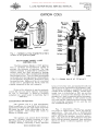
Ignition Coils. . . . . . . . . . . . . . . . . . . . . . . . . . . . . . .• . • . . . . . . . . . . . . . . . . . .
1. Z.
SECTION "D"
Distributors
1 to 3
SECTION "E"
Generators " .. , .......... , ........ " " " .... , . , .... " .................................................. " .
11 Z
SECTION "F"
Headlights. . . . . . . . • . . . . . • . • . . . . . . • . . . . . . . . . . . . . . . . . . . • . • . . . . • •.
1 to 4
SECTION "G"
Horn . . . . • . . . . . . . . . . . . . . . . . . . . . . .. '. . . . . . . • . . . . . • . . . . . . • . . . . . .
1, Z.
SECTION "HI!
Regulators . . . . . . . . . . . . . . . . . . . . . . . . . . . . . . . . . . . • . . . . . . . • . . . . . • ..
1 to 8
SECTION "I"
Spark Plugs. . . . . . . . . . . . . . . . . . . . . . . . . . • . . . . . . . . . . . . . . . . . . . • . • . ..
SECTION
II
J"
Starting Motors (Cranking Motors) . . . . . . . . . . . . . . . . . . • . . . . . • . • . . . . . • . .•
PRINTED CN UNITED 5TAT£S 0,. AMERICA
1 to 4
1 to 4 .
Donated by John & Susan Hansen - For Personal Use Only
Donated by John & Susan Hansen - For Personal Use Only
E~ ("l
;;l
'I;;::
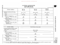
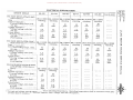
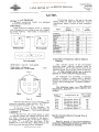
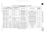
ELECTRICAL SPECIFICATIONS R-110 THROUGH RF-210 (NOT RA-120, RA-140) >
F;
:x:
~
'"v;
c
"'i!.
ENGINE MODELS
~
RD-372 RD-406 RD-450 SD-220
SD-240
BD-269
BD-282
DR-llOOO19
DR-ll02785
DR-ll02785
1.85-2.03
1.90-2.05
1.90-2.05
[
-g
;
~ ~ 'f'
GENERATOR {Delco-Remy} . . . . . . Field current {at 6 volts}
amperes . . . . . . . . . . . . . . . .
¢'
r-.
Cold output:
Amperes . . . . . . . . . . . . . . .
Volts . . . . . . . . . . . . . . . . .
R.P.M . . . . . . . . . . . . . . . . . Hot o utput:
Amperes { Controlled} . . .
by current
...
Volts
regulator
..•
R.P.M.
35
8
2650
45
8
2450
Z
['I1
s::
45
8
2450
~:::0 · .................... · . . . . . . . . . . . . . . . . . . .. ·
.................... -l
~
· .................... · .................... ··
....................
· . . . . . . . . . . . . . . . . . . . . · .................... .................... n
?':
Ul
Regulation. . • . • . . . . . . . . . . .
volt. and current
Brush tension {ounces} . . . . . . •
28
volt. and current
28
~
volt. and current
n
28
Bearing - commutator end . . . . .
bronze
bronze
bronze
Bearing - drive end . . . . .' . . . .
ball
ball
ball
Rot.ation {viewed from drive end}.
CW
CW
CW
['I1
en
l'1
t'
'1:j
l'1
(1)
Type of drive . . . . . . . . . . . . . .
belt ..
belt
belt
C..... ()
en~
~'t--<:
..
'tl~en~
:
~.
J.-j ()
o l'1>
.... ~~t"'
(1)
Donated by John & Susan Hansen - For Personal Use Only
'U Clltll t'1
I-<! I:"'
CIl t'1
I» "d
QQ(\
('0
8. ioi 0
N::!!t'1 ioi
~~~
.....
.... 0.....
o
>
;
I:"'
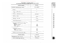
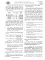
ELECTRICAL SPECIFICATIONS
RA-120, RA-140
-
-
-_........
_._ __ _._
..
........
......
__
............
E~GINE
-
-
SD-220 MODEL
GENERATOR (LOW SPEED CUT-IN)
(Deleo - Remy). . . . . . . . . . . . . . . . . . . . . . . . .
DR-II05876
A=peres { Controlled
Volts
R.p.m.
by current
regulator
1J .............
.............
25 8.0 ...
..
'"
'"
.
Brush tension (ounces) . . • . . . . . • . . . . . . . .
'"
~
'" '" '" '" ,. ., .
. • . . . • . . . . . . . . .. .. .. ..
Regulation. . . . . . . . . . . . . • . . . . . . . . . . . .
r
Z
(T]
Cold output:
Amperes . . • . . . . . . • . . . . . . . • . . . . . . .
Volts . . . . . . . . . . • . . . . . . • . . . . . . . . .
Hot output:
¢'
1.62-1.82
Field current (at 6 vOlts) amperes . . . . . . • . . •
'" '" '"
'" '"
. . ..
'"
'" '"
. '"
.. ..
"
,.
.
'" '" ,.
.. ..
'" '"
$::
~
.
'"
.
.. .. .
'"
.
'" '"
'" '" '" ,. .
..
'"
.
" '"
'" ,. '"
..
'" ,.
.. .. ..
'" '"
..
,.
..
.
'" '"
.
'" '"
.
. '"
,.
..
'"
...
28 '"
"
"~
-i C
Ul ~()
(T]
Bearing - commutator end . . . . . . . • • . . . . . .
ball
Bearing - drive end . • . . . . . • . . . • . . . . . . .
ball
Rotation (viewed from drive end) . . . . . . . . . . .
CW
Type of drive . . . . • . • . • . • . • . . . . . . . . . . •
belt
---_._
....
_
Em
Donated by John & Susan Hansen - For Personal Use Only
q
~
~
'"v;
BD-269
BD-282
SD-220
SD-l40.
ENGINE MODELS
C
~p
RD-371
RD-406
RD-450
-------
'0
'E.
E
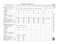
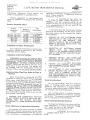
ELECTRICAL SPECIFICATIONS
R-110 THRU RF- 210
(NOT RA-120, RA-140)
'"
VOLTAGE REGULATOR (Delco
Remy) • . • • . . . • . • • . . . . . . . .
DR-1118731
DR-1l18732
DR-1118732
Amps . . . . . . . • . . . . . • . . . . .
35
45
45 ~
Type . . . . . . . . . . . . . . . . . . •
vibrating
vibrating
vibrating 'f
Current regulator:
*Current setting-amps. (hot) ..
Air gap. . . . . . . . . . • . • . . .
38
.075"
47
.075"
47
.075"
r· Voltage regulator:
*Voltage setting-volts. (hot) . . .
Air gap . . . . • . . . . . . . . . . •
7.4
.075"
7.4
.075"
7.4
.075"
:::
Cutout relay:
*Closing voltage-volts. (hot) ..
Air gap. . . . . . . . . . . . . . . .
Point opening. . . . . . . . . • . .
6.4
.020"
.020"
6.4
.020"
.020"
6.4 .020" .020" !
'0
~
q
~
Z
[T1
~
;;:f
C
7':
()
SD-220 (RA-120, RA-140)
ENGINE MODEL
Ul
VOLTAGE REGULATOR-25 AMP.
LOW SPEED CUT -IN (DelcoRem y) . . . • . . . . . • . . . . . . . ••
~
DR-1118350
Type . . . . . . . . • . . . . . • . . . .
vibrating Current regulator:
*Current setting-amps. (hot) ..
Air gap. . . . . . . . . . . . . . • .
25
.075"
Voltage regulator:
*Voltage setting-volts (hot) •..
Air gap. . . . . . . . . . . . . . . . 7.2
.075"
. CI,ltout relay: *Closing voltage-volts (hot) ..•
Air gap. . . . . . . . . . . . . . . .
Point opening. . • . . . . . . . . .
()
[T1
l'l
t"
l'l
8.
0
....(f.l-->
...
>-< ., (f.l
6.4
.020"
.020"
'1j
(Q
'tjC"l(f.l!:t1
11'11'
H
::t., 0
(Qol'l>
OQ
p
g
p
!.»;~t"
Donated by John & Susan Hansen - For Personal Use Only
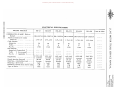
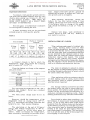
ELECTRICAL SPECIFICAfIONS
IQCIlCllM
R-170 and RF-170 Series, R-180 thru 184, RC-180, 181, 182
O\:lCltCllM
\ll'l:lt<t"
CIt
ENGINE MODEL
BD-282
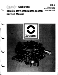
STARTING MOTOR (Delco-Remy) . . . . . • . . . • .
DR-II08009
Voltage. • . . . . . . • . . . . . . . . . . . . . . . . . . .
6
Number of field coils . . . . . . . . . . . . . . . . . .
4
Bearing - commutator end • . . . . . . . . . . . . . .
cast iron
Bearing - center . . . . . . . . . . . . . . . . . . . . .
bronze
Bearing - drive end . • . . . • . . • . . . . . . . . . .
bronze
Brush tension (ounces) . . . • . . . . . • . . • . . . •
24-28
No-load test (with Solenoid or Magnetic
Switch):
Maximum amperes • . . . • . . . . . . . . . . . . .
Volts . • . . • . . . . . . • . . • . . . • . . . . . . . .
R.p.m. approx • . . . . . . • . . . . . . . . . . . . . 70
5.65 5500 Lock test:
Maximum amperes . . . . . . . . . . . . . . . . . .
Volts . . . . . . . . . . • . . • . . . . . . . . . . . . .
Torque (lb. ft.) (min.) . • . • . . . . . . • . . . • .
570
3.15
13.5 Rotation (viewed from drive end) . . . . . . . . . . . CW ....~a::~(')
g >
CII
t"
l'
r Z
[Tl
::
~
~
~
til
~
~
ENGINE MODEL
BD-282 DISTRIBUTOR (Delco-Remy) . • . . • . . . . . . . . . .
DR-1112359
Initial setting (engine degrees) . . . . . . . . . . . •
n. "" (')
.r:.!:!M""
6 o B.T.C.
E~
Donated by John & Susan Hansen - For Personal Use Only
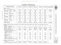
ELECTRICAL SPECIFICATIONS ENGINE MODELS
SD-220
SD-240
BD-269
RD-372
RD-406
RD-450
Cont. R-6602
COIL (Delco-Remy) • . • . • . . . . . DR-11l5327 DR-1115327 DR-11l5327 DR-11l5327 DR-lllS327 DR-lllS327 DR-lllS2S1
DISTRIB UTOR • • • . • . • . • . . • • . DR-1l12355 DR-1l12355 DR-l112359 DR-1l12357 DR-1l12357 DR-11l23S7
Type . '" ............ '" . . . . . . . . . . . . .
vac. auto
vac. auto
automatic
automatic
automatic
automatic
Cam angle • • • . . . • . • .
31 °_37°
31 °_37°
35°
35°
35°
35°
Initial setting (engine degrees) ••
20 BTC
2° BTC
3° BTC
r§> BTC
5° BTC
5° BTC
Vacuum advance (engine degrees)
15°
15°
none
none
none
none
Automatic advance (engine
degrees) • • . . . • . • . • . • . • •
30°
30°
27°
22°
22°
22°
Total advance (engine degrees) •.
32°
32°
30°
27°
27°
27°
selective
none
none
none
none
Retard (engine degrees) . . • . . . • { selective
20°
20°
none
none
none
none
Contact point setting . • . • . • . • .
.022"
.022"
.018-.024
.018-.024
.018-.024
.018-.024
Contact point pressure (ounces) .
17-21
17-21
17-21
17-21
17-21
17-21
Rotation (viewed from top) . • . • .
CCW
CCW
CW
CW
CW
CW
Firing order . . • . • . • . • . • . • •
153624
153624
153624
153624
153624
153624
4
automatic
•••••
r
t
zf11
3:
~
o
:;u
-;
:;u
C
()
CCW
7':
en
f11
*DISTRIBUTOR TEST DATA
Start advance:
Engine r.p.m• • . • . • • • . • . • .
500
500
0
Engine degrees . • . • • • . • . • •
2°
2
Intermediate advance:
Engine r.p.m• • . • . • • • . • • • •
1800
1800
0
0
Engine degrees . • . • . • . • • • .
20
20
Macimum advance:
Engine r.p.m• • . • . • . • • • . • •
3000
3000
Engine degrees . • . . . . . • . • .
30°
30°
Distributor vacuum control
(De1co-Remy) • . . • . . • • • • . DR-1116049 DR-1116049
:;u
n<
400
0
1.5
500
0
1.5
500
0
1.5
500
0
1.5
1800
20°
1400
13°
1400
0
13
1400
0
13
2700
0
27
**3200
22°
**3200
22°
**3200
22°
. ..
..
.. .
.. '"
* Distributor Test Stand figures will be one-half of these specifications.
** Test Stand r.p.m. only. For maximum engine r.p.m. see "Engine Section."
[Tl
3:
:J>
z
C
:J>
.
'"
.
. ...
'"
..
'"
.
'"
..
r
'" .. '"
. ..
00
M
~
M
"d
t-'
8.
()
...... 00....,
.... ><: .-,
1:J~oo~
Il>~l-:l()
OQoM>
rD::J!:>,t-'
~(Il;::"
Donated by John & Susan Hansen - For Personal Use Only
ELECTRICAL SPECIFICATIONS 11
UHIl M
1\1'0 >-<t""
OQ(1)(flM
ENGINE MODELS
SD-220
GENERATOR-50 AMP. (Delco-
Remy) . . • . • . • . • . . .
Field current (at 6 volts)
amperes . . . . • • . . . • .
Cold output:
Amperes.
Volts . • • . • . •
R.p.m• . • . •
Hot output:-
SD-240
BD-269
RD-372
RD-406 RD-450
Cont. R-6602
8. ..., C'l
~l1::::o
......
<+
....
DR-ll06757 I DR-ll06757I DR-ll06757I DR-ll06757I DR-ll06757 I DR-ll06757 I DR-ll06822
1.70-1.95
1. 70-1.95
1.70-l.95
1. 70-1.95
1.70-1.95
1.70-1.95 50
7.5
1410
50
7.5
1410
50 7.5 1410 50
7.5
1410
50
7.5
1410
50
7.5
1410
50 7.5
r
[T1
3:
volt. and
Regulation. . . • • . • • • . •
{ curren t Brush tension (ounces) . .
25
Bearing - commutator end. •
ball
Bearing - drive end . . . • . •
ball
Rotation (viewed from drive·end).
CW
Type of drive. . • . • • • . • . . . • .
belt
GENERATOR (LOW SPEED CUT
IN) (Delco-Remy) . • . •
Field current (at 6 volts)
amperes . • . •
Cold output:
Amperes.
Volts • . . . •
R.p.m• . • . • Hot output:
volt. and
current
25
ball
ball
CW
belt
••• I
Brush tension (ounces)
Bearing - commutator end . • . •
Bearing - drive end . . . • . • . •
Rotation (viewed from drive end).
Type of drive . . • . . . . . • . • . •
volt. and
current
25
ball ball CW
belt
volt. and
current
25
ball
ball
CW
belt
volt. and
current
25 ball ball CW
belt
volt. and
current
~
o
::0
--l
::0
C
()
belt
7':
{J)
[T1
DR-ll06758 I DR-ll06758
1. 70-1.95
1.70-1.95
40
7.5
1165
40
7.5
1165
AmpereS) Controlled {.
Volts
by current •
R.p.m.
regulator.
•
volt. and
current
25 ball
ball
CW
belt
{
volt. and
current
20 bali
ball
CW belt
volt. and}
current 20
ball ball CW belt C'l
g
>t""
ID
tz
AmpereS}Controlled {.
Volts
by current •
R.p.m. regulator.
Regulation. . • . • . . . •
(1)
N~M...,
::0
n<
[T1
3:
»
z
c
»
r
Donated by John & Susan Hansen - For Personal Use Only
ELECTRICAL SPECIFICATIONS
ENGINE MODELS
GENERATOR-30 AMP. (Delco
Remy) . . . . . . • . • . •
Field current (at 6 volts) amperes. •
. ..... Cold output: Amperes.
Volts ••••• R.p.m • . . . •
Hot output:-
SD-220
SD-240
BD-269
RD-372
RD-406
RD-450
DR-1102714 I DR-II02714 I DR-II027141 DR-II02714 I DR-I1027141 DR-II02714
1.75-1.90
1.75-1.90
1.75-1.90
1.75-1.90
1.75-1.90
1. 75-1.90
30
8
1750
30
8
1750
30
8
1750
30
8
1750
30
8
1750
30 8
1750
Regulation. . • . • . • . • .
~
o-l
o;;.0
Sci
c() A
1"
Amperes} Controlled
Volts
by current '"
R.p.m. regulator
••
Cont. R-6602
Ul
[Tl
;;.0
{ v~it" ~~d
current
24-28
Brush tension (ounces) . • . •
bronze
Bearing - commutator end .•
ball
Bearing - drive end . • . • • •
CW
Rotation (viewed from drive end).
belt
of drive . . • • . . • • . . • . • . volt. and
current
24-28
bronze
ball
volt. and
current
24-28
bronze
ball
volt. and
current
24-28
bronze
ball
volt. and
current
24-28
bronze
ball
volt. and
current
24-28
bronze ball
CW
CW
CW
CW
CW
belt
belt
belt
belt
belt
n<
[Tl
~
»z c
»r
en
M
(!)
M
"0
8.
t""'
()
'""en'-'!
..... ....: '-:l
'U ~ en?:!
PI::ti-l()
(lQOM>
(!)i:I!7t"'
wm;::..
Donated by John & Susan Hansen - For Personal Use Only
ELECTRICAL SPECIFICATIONS ENGINE MODELS
VOLTAGE REGULATOR-30 AMP.
(Delco-Remy) • . . . . • . . . .
Type . . . . . . . • . • . . . . . • • .
Current regulator:
*Current setting-amps. (hot)
Air gap. . . . . . . . . . . . .
V oltage regula tor:
*Voltage setting-volts (hot) .•
Air gap. . . . . . • • . . • . . .
Cutout relay:
*Closing voltage-volts (hot).
Air gap. . . . •
Point opening. . • . • . .
SD-220
SD-240
trl (/) (f.!I."l
fl) '"0 >< r
(l) (/) M
()'Q
BD-269
RD-372
RD-406
RD-450
Cont. R-6602
DR-IllB303 IDR-IllB303 IDR-IllB303 I DR-IllB303 I DR-IllB303 I DR-IllB303
vibrating
vibrating
vibrating
vibrating
vibrating
vibrating
30
.075"
30
.075"
30
.075"
30
.075"
30
.075"
30 .075" 7.4
· 075"
7.4
•075"
7.4
.075"
7.4
.075"
7.4
.075"
7.4
.075"
6.4
· 020"
.020"
6.4
.020"
.020 11
6.4
• 020"
.020"
6.4
.020"
•020"
6.4
• 020"
.020"
6.4 .020"
.020"
VOLTAGE REGULATOR-50 AMP.
HIGH OUTPUT (Delco-Remy). DR-1118333 IDR-IllB333 IDR-llIB333 IDR-1l18333 IDR-ll1B333 I DR-1l18333 I DR-ll1B368
Type . . • . . . . . . • . . . • . . .
vibrating
vibrating
vibrating
vibrating
vibrating
vibrating
vibrating Current regulator:
Current setting-amps. (hot)
50
50 50 50
50
50
50
Air gap. . . . • . . . . . . . . .
.OB2"
• OB 2"
.OB2"
.OB2"
.082"
• 082"
.075"
Voltage regulator:
*Voltage setting-volts (hot) .
7.4
7.4
7.4
7.4
7.4
7.4
14.3
Air gap. . • . . . • . . . . . . .
.075"
.075"
•07 5"
•07 511
.075"
.075"
•075"
Cutout relay:
*Closing v oltage-volts (hot).
6.4
6.4
6.4
6.4
6.4
6.4
12.B
Air gap. . . . .
.020"
· 020"
.020"
.020"
.020"
.020"
.020"
Point opening. . . . . . . . . .
.020"
.020"
.020"
.020"
•020"
.020"
. 020"
*
VOLTAGE REGULATOR-40 AMP.
LOW SPEED CUTIN (DelcoRemy) . . • . • . . . . . . . .
Type . . . . . . . . . . . . . • . • . .
Current regulator:
*Current setting-amps. (hot) .
Air gap, . . . . . . . . . . . . .
Vol tage re gulator:
Voltage setting-volts (hot) . Air gap. . • . . . • . . Cutout relay:
*Closing v oltage-volts (hot)~
Air gap. . . . •
Point opening. . , . . . • . . . .
*
* Current and voltage
8. '"'l ()
*,"::l!M'"'l
(l)
~~::o
.....
<+
.....
r
tz
[T1
~
~
o
:::0
-I
:::0
C
()
7':
(f)
~
<
n
[T1
~
DR-1118366 IDR-II1B366
vibrating
vibrating
40
.075"
40
.075"
7.4
• 07 5"
7.4
.075"
6.4
.020"
· 020"
6.4 .020" .020" specifications apply only at operating temperature. Operating temperature shall be assumed to exist after
not less than 15 minutes of continuous operation with a charge rate of B-I0 amperes.
()
gm >
r
»
z
c
»
r
Donated by John & Susan Hansen - For Personal Use Only
ELECTRICAL SPECIFICATIONS ENGINE MOD.ELS
SD-220
SD-240
BD-269
RD-372
RD-406
RD-450
Cont. R-6602
AC
} "standard" { proChampion
heavy
ducAuto-Lite
service
tion
44 Corn
44 Corn.
45 Corn.
43 Corn.
43 Corn.
43 Corn.
J-7
J-7
J-8
J-6
AN5
J-6
J-6
AN5
AN7
AN5
AN5
AN5
82 Corn.
5 Corn.
BT4
AC
} "hot"
{ .
Champion
mod~rate
.
Auto-Lite
service
.
45 Corn.
45 Corn.
45 Corn.
44 Corn.
44 Corn.
44 Corn.
J-8
J-8
J-8
J-7
J-7
J-7
AN7
AN7
AN7
AN7
AN7
AN7
AC
} "standard" { .
Champion
heavy
•
Auto-Lite
service
.
44 Corn.
44 Corn.
45 Corn.
43 Corn.
43 Corn.
43 Corn.
J-7
J-7
J-8
J-6
J-6
AN5
J-6
AN5
AN7
AN5
AN5
AN5
43 Corn.
43 Corn.
44 Corn.
43 Corn.
43 Corn.
J-6
43 Corn.
J-6
J-6
AN5
J-6
AN5
J-7
AN5
J-6
AN5
AN5
AN5
14 mm
.028-.032
14 mm
.028-.032
14 rnrn
.028-.032
14 mm
.028-.032
14 mm
.028-.032
14 mm
.028-.032
SPARK PLUGS
~
~
~
c
AC
} "cold"
Champion
severe
Auto-Lite
service
.....
......
. . . .. ..
{
Spark plug size
Spark plug gap .•
r:
c
z
82 Corn.
5 Corn.
BT4
[T1
3:
o-l
o
;0
-l
18 mm .023-.027 ;0
C
(')
STARTING MOTOR (Delco-Remy) I DR-ll07074I DR-II070741 DR-ll07967I DR-ll082171 DR-II090041 DR-ll09004
Voltage. . . . . . • . • . . . . . . . • .
6
6
6
I
6
6
6
Number of field coils . • • . • . • .
2
2
4
4
6
6
Bearing - commutator end .•
cast iron
cast iron
cast iron
cast iron
cast iron
cast iron
Bearing - center . . . .
cast iron
cast iron
cast iron
Bearing - drive end . . . • .
bronze
bronze
bronze
bronze
bronze
bronze
Brush tension (ounces) . • .
24-28
24-28
24-28
24-28
36-40
36-40
No-load test (with Solenoid or
Magnetic Switch):
Maximum amperes .•
75
75
60
70
70
70
Volts . . . . . . . . • .
5.7
5.7
5.0
5.0
5.7
5.7
R.p.m. approx. . . . •
5000
5000
6000
3500
2200
2200
Lock test:
Maximum amperes. •
525
525
600
600
600
600
Volts. . . . • . . . . . •
3.4
3.4
3.0
3.0
3.0
3.0
Torque (lb.ft.)(min.) .
12
12
15
22
35
35
Rotation (viewed from drive end).
CW
CW
CW
CW
CW
CW
12 6
;0
[T1
<
bronze (')
[T1
bronze 36-40 $:
:t>
z
C
65
11.4
6000
:t>
r
725
5.0
44
CW
(Jl
M
'U t"'
....
Cl
~
M
~(Jl>-3
MAGNETIC SWITCH (DelcoRemy) • . . . . . • . • . . . • . "1
Current consumption (at 6 volts).
A
(f)
n
PlPl(Jl ....
OQ ~ >-3 Cl
'1:J
DR-1465
5.7-7.0
DR-1465
5.7-7.0
DR-1465
5.7-7.0
DR-1465
5.7-7.0
DR-1465
5.7-7.0
DR-1465
5.7-7.0
><::o
roOM~
lTI~g:t"'
Donated by John & Susan Hansen - For Personal Use Only
~CJ)CJ)1:'1
I» 'U
-< t:-'
OQ(1)CJ)1:'1
(1) 8.1-3(1
0--:::-:1:'11-3
R~~
(1
ELECTRICAL SPECIFICATIONS
....
ENGINE MODELS
SD-220
SD-240
BD-269
RD-372
RD-406
RD-450
Cont. R-6602
HEADLIGHT SEALED-BEAM
UNIT (Guide) . . • . • . . . • . • .
924791
924791
924791
924791
924791
924791
5930856
IGNlTION SWITCH (Delco-Rern.y).
1116465
1116465
1116465
1116465
1116465
1116465
1116465
LAMPS (BULBS)
Stop and tail light bulb:
Voltage . • . . . •
Candle power . . . •
Contact. • . • . • . •
Parking light bulb:
Voltage. . . . . .
Candle power . • . •
Contact. • . • . . . • . •
Instrurn.ent light bulb:-'
Voltage . • . • . •
Candle power . • . • . •
Contact. • . • . . . • . •
Beam. Indicator bulb:
Voltage . • . • . • .
Candle power . • . • . •
Contact. • . • . • . • . • . • .
~ ~
r
t
z
[Tl
6-8
21-3
DC
6-8
21-3
DC 6-8
21-3
DC
6-8
21-3
DC
6-8
21-3
DC
6-8
21-3
DC
12-16
21-6 DC
6-8
3
SC
6-8
3
SC
6-8
3
SC
6-8
3
SC
6-8
3
SC
6-8
3
SC
12-16
3
SC
6-8
6-8
6-8
6-8
6-8
2
2
2
2
2
SC
SC
SC
6-8
2
SC
SC
SC
12-16
1.5
SC
6-8
6-8
1
SC 6-8
1
SC
6-8
6-8
1
SC
6-8
12-16
1
SC
1
SC
s:
@
::;0
1
SC
1
SC
STORAGE BATTERY
Type (Auto-Lite) .•
2H-I05
2H-I05
2H-135R
4H-152R
4H-152R
4H-152R
4H-152R
Specific gravity:
Fully charged at.
1.280-1.290 11.280-1.290 11.280-1.290 11.280-1.290 11.280-1.290 11.280-1.290 11.280-1.290
Recharge at. . . . .
1.225
1.225
1.225
1.225
1.225
1.225
1.225 Voltage . . • . • . • . • . 6
6 6 6
6 6 6
Arn.peres hours at 20-hour rate.
105
105 135
152
152
152 I
152
Arn.peres-20 rn.inute rate.
133
133
170
180
180
180
180
Terrn.inal grounded •••••.••••
positive
positive
positive
positive
positive
positive
positive
-;
::;0
C
n
7':
fJJ
[Tl
::;0
~
n[Tl
s:
>z
c
r>
Donated by John & Susan Hansen - For Personal Use Only
Q
'J>
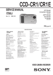
Cable Color
or
"
~
"'"
Fi:t
Description
r=eh4~eratOrficl.r:::-.~·
8 :""'Toenerator ann.
Em
.
~
Vi
c
"0
'!1.
1
'g
!!
®
~
q
'{'
,.....1-
Battery
!
.-_" I
:~
~~Hom
relaY-R.H.n
®-
F~ Modol,
~~ I 1"::\
............ Starting push switch
"and R·163 ~ (U) (ll)""--, . .
}R.H 0.1. _ \yindshield
~~:tl====±='l'-(~ '<, b IlgmtIon switch :.- >'1"'-- Wlper motor
Fuol
R·l53
::c
•
I
~
~14 "-H--LI.
/,
(20)
~
•
\
Temp'
@i ___L
Cab"
ground!
C
%
A~m. P, A ----I1...-----"'----- ,. /
w~_\.9I"t-_.....J _....1"'"FuelI .I / .%I
"
!I"
"m~
0
"
"~
0"
~
/ Dome light
/
switch
Dome light
1
B
D
1:2
E
1
F
16
G
14
P
16
16
---~-/i
L.H.D.
--Stop light switch
~ ,..>!:!!J
4
~
en
-~
()
[l"J
/~- r:;;;,.-
14 g a . ! J o Y
\:Z)
L.H.D.
c::
()
.J rV~i~:!~h"~nd ignition
7tJ1/
r:;X
® Y"/('''
'(z6)
~
;a
---;- l=®. /Inott.:': "",k"~
,--:>,
-~
"
::c
~S'-t~-:::.:1-::::J
- ij-----High
-lnstr. light
I I
L__
I
L;;+====::J~
:;
~
0....,
0
u,h< ""tch I
I
I~{
Horn~
26
[l"J
.
1
Bat. coil
__
I
.--_+--!til
'~Ig:t'"
_
'"
Z
""1,-yJ ! rTi\ r"'-- ---:B
~ & ~~. /
i
Windshi Id
3 ~T· ';;;-iil';Jl! ~~l--I "'--"",wiper swi~ch
2 or P"'I""'"
/ CirclntF:ltG-Circuit
/bre~e!S~:;~;l--breaker
I' or,' b~t.1 t
" " \\
... 1
Junction I
block /
r'
........ f4Y
d
'---1~,.a~..::.::...----'
Bat \::..J
R
•
egulator
\ ',\
®
Hom
..
I \
1
\
Fuel..:::-;-Trailer taillight
.......... T
\i[]nectors
\ 22
bu""""
16.
14 :::;
.
~6
.1;......
.. ad
gao 21
railer stop light
~:l~ :;~ 130 left hd. IL
14 ga.: R ..110 t o R,,165
~ft hd.
,,165 nght
hd.It.It.
Enlatged view
A.A
Ul .n ()
ll>"'l-j
8·TI66
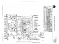
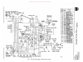
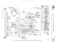
Fig. I· Wiring circuit diagram. (R·llO, R.120, R·1lO, R·150, R·160 series trucks)
l"l
I:"'
l"l
t-cl~...c:~
II> ....
~
.....
~§M~
..... ~s;:1:"'
Donated by John & Susan Hansen - For Personal Use Only
'UtntnM
IlIC11~t"'
Parking light
ID--.
rtf;
J
OQ::l.tnM
~ .... 1-3 C"l
NgMI-3
,@16 ga.,
}<@16
ga·1 ~
/~
rYFi:"
Headlight ~"®
'"
I Cab ground
'\
Light
switch
Starting motor
Generator
'\
. . . -.-®
----0
<E<
]//@
~~~ J/~Ignition
I
tis<
lw
~
and
starting switch
J/
/Y
1
1 -®
~+k~'
f
~
Cable Color
or Description
I
16
8
8
5
12
11
8
12
16
14
15
16
17
17
17
16
12
12
1204
16
16
18
16
18
Generator aeld
Generator arm.
Regulator to ammeter
Ammeter feed
Ignition switch feed
Ignition switch to Ig.
nltlon coU
Starting
Light switch feed
Dimmer switch feed
High beam feed
High beam indicator
High beam head.
light leads
Low beam head.
light leads
Low beam feed
Parking light leads
Parking light feed
Tail.light
Stop light
Connector 10 relay
HOJ'n and horn re
lay feeds
Horn and stop light
feed
Instrumenl feed
FuelgBuge
Temperature gauge
011 pressure gauge
Dome light
Instrument lights
Ignition call to dte·
tributor
Headlight ground
Battery ground
Engine ground
Cab ground
BB!:'&'cable
Horn utton to con·
nector
2
4
//~
I
I
--::-In
Junction
block
Circuit
breaker
11/1111
?A+<:=::~~M
Bmm 'n&aOX
1.,/ 4.0)
21
22
25
26
14t16
16
1608
16
16
16
1204
-' .®
26
12
27
30
33
36
38
40
80
16
18
18
18
18
16
16
91
14
4
3
12
1
16
20
20
--/ ' 40
11kJ.1
I Hom
B
Fuel I
I I I
I I-I-T
,...-_ _ _ _ _ _..11"'"
;..-!5:::c
....
Cable
Gauge
Lott.o
I
"I~I"
gao
--
Ckcui.tNo.
C
·.I~II'
~
,,~"'@
''(26)
~Hom button Engine ground
J-® ~I
I I -_
I
-~
1=
StoP, light
sWitch
~
D
E
H
0)
Dome light
~
21)
C"l
;..
t"'
r~
Z
[T1
~.
~
:;0
;1
C
()
~
UJ
~-
()
[T1
Fuel
~
A
""'I
Stop
OOi?Tt
I
8-7181
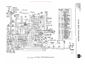
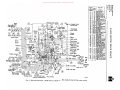
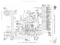
Fig. 2· Wiring circuit diagram. (RM.l20. RM.150 series trucks)
E-
Donated by John & Susan Hansen - For Personal Use Only
9
~
II
®a.
@),!
®Battery
17
18,
@
1
1
~
j
'"
<Ii
!
l
/
I
/' "
/' "'II~
I
/'
F
Q
Junction block
/.:
A
Generator
)..:::J
/
~~.....
Temperature
t
fl\.--.-.. .
v
0.....
'12
~
x.v
/'4 or H,
3 or T ,\ 2 or P "", ,
1 or bat.\ \, ,
Distributor
\\
D' ~IIJ~[==~~~~
switch >l,
"Light
_1- Speedometer
~ I H'gh bea m I - indicator light . ~
-_~
,
(i8)___
~'
~~
'--t-'+'~-:rir-_+-H-_..!.I..:::J ~
~~,
\
"'
',
I
II
\
'J
I \
\
~,
1
Connector' 6
~
~
C
~
)Sin
/
\
~ D
E
F
rJg\
-~----~
P
G
H
Stop 7;JI (TUI
14
16
16
~
~
\\ ~1
16 a.
E la d •
n rge View
A.A
\ Trailer stop light
'Trailer tail light
\\
----:Ell
"" \
Hom button
::0
8'
~~~~~~~~,:itch
,
L--\
-----70
light
sWitch
Hom Hom
I
relay
d
40
71
80
91
A
:ht
Dom~
~
te1~~/f ~~'~;
I..
o
36 38
1
~l--Fuel
3::
" 33-' Amm·0
r-T"l--Instr. light
h
~
27
30
--:::=:::---
~--I'
~ P I •
r-.
26 .....
"'P"
::0
26 .1-.. . Instrument light .@
Oil preS8ure_~
Dimmer switch- - - •
.
22
40 ....
cab}® ground "'\ ~ r/
®~
field
"r>.
17
17
18
18
20
20
21
C"Ircult
breaker
33 -= "
~ I ~
l
~
Em 14
15
16
17
~
L18 ga,@' ~,/
114 gao
-5
11
M
Starting motor
,/
Cable Color
or
Description
-~--r-
\V~II'
~
~
2
=:-.
11
g'
Circuit
No.
Cable
'r Index Gauge
Letter
1
' 16
\\
\
F~l
I12 gao II 14 gao I ~
(zO) ~
'(z6) ~
li6) F'-=\-J'"
tIl
Gen. Bat, Regulator Fig, 3. Wiring circuit diagram. (RC.l60 series trucks)
g
I:-l
l""
I:-l
oooon
8-7179 ~ .... '":1
't1 n ,",,'.D
1ll1t.~H
~gl:-l~
w>!S:l""
Donated by John & Susan Hansen - For Personal Use Only
'ijCf.lCf.lt<J
Cable
Gauge
1lIn>><t-'
~Cf.lM
n> ...'., ()
Cable Color
OQ
"",gt<J.,
>-~~
()
>t-'
®..-,-____s.:a~ng push switch
)-.,!If
JR. R. D.
l r-r--lS~~~~~~tCh
II
'
:
l---h
I ,1--.1
L I
""'-.
-@
I
/"'.
I
Windshield
wiper motor
l'
r
Z
[T1
For Models R.173 and R·183 Windshield
/' /' /' wiper switch
E:"
o
d
:::0
Circuit
--breaker
~n - -Speedometer
- -Instrument light
~
- - High beam indicator
- -Instr. light
'-'''/ Dome light switch
G
H
p
Dome light
14
l~
16
I ........
a.un..
PUbU DUUVU
..'1
..
•..
I
~
()
[T1
•
Starting and ignition switch- L.R.D. Stop
Stop light switch
,J
I
Tail
" 'Trailer stop light
"Trailer tail light
Enlarged view
A.A
Stop and tail light
B·TlIl1
Fig. 4 - Wiring circuit diagram. (R-170, RF-170, R-180 series trucks-not R-185)
Em
Donated by John & Susan Hansen - For Personal Use Only
a
E~
'I
:;:
>
:<'
/")
:I: Cable Color ~
~
r;;
c
~3
Q
~
!!.
Park Head[l~'[email protected]
Light light
I
AI I
/
J
91
//~
17
I
I;
I
'g
"~
18
/
...
® "-'~V
; B
i/,~atte~1I
®
;/
I
/ 4 or H,
;~:~,
a
Sl
'f
--
i2o)
I.
[18~1
-I
~
Junction block
Distribu~
118
116
_
ga.@--i I
~j ~
130rT\
,
\
2 or
\\
II
p,\ \
or bat. \ \ \
~
I'\\~i
r'
Z
[T]
s::
ga.~---t1_
~
ga'®-:J L
(D-- [L
CD-Dimmer switch ~IJ
114
1
.,.--
~
()
~
Hom relaY '!.1
11~r
20
E
F
Hom.
Junction block
\
~
~
B
D
Enlarged view
"
A·A
.."
__9H _
n
. . .,.
1~
1""&i:"··IU~
u... _... _ "L"""""'''''''''''''!
L"".__
[T]
~L
p
i
button
"z
c:
z
\
\
Park
Light
._W-~"
\
,
F. Gen. Bat.
Regulator
\,
'\C'trcwt
. breaker and
terminal block assembly
l:"l
t'"
B-T/SO
l:"l
C/l ." (")
ro .. 1-3
14
"tl~><~
ill ..... 00 ....
(lQol-3(")
Fig. 5. Wiring circuit diagram. (RC.180 series trucks)
ro::ll:'1>
...,,>E:t'"
Donated by John & Susan Hansen - For Personal Use Only
"tJ tlltll trl
lUn><t"'
I.lQ ~ (I)
III ..... .,
t::l
C'l
O"gtrl.,
>E:~
~
t"'
Fuel
';p
r
Z
[T1
3:
~
(i7)--
~
;;:J
I
(iO}. ___
Distributor
R
1
~
~
r.n
~
Engine ground
@
8-7168
(R.185 truck and R·190, RF.190, R.200, R·210, RF·210 series trucks)
Ell
Donated by John & Susan Hansen - For Personal Use Only
E·
a
r
lI:
~
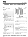
PARK
LIGHt
g
20
~....
r--------
---~
f
;;
~0
E.
GENERATOR
:Ji
I
rI
II
I
II I
r'
r --,_
\
START·PUSH SWITCH·RHO \~
)
B I IGNITION
B
~.
Ii
.•
(
If
~
I
'
SWITCH.RHO
.
I~---------t----+-+---~
I
I:
. \§,;"-------------~
'0
iii
I
I
I
JUNCTION BLOCK
I
-'"'
P !( 16ilh:Jf11iIii
!
~
~,¥:HJSW(TCH
"
~
=:a
r·
LIGHTER
Z
[T']
~
~
()
~
til
~
~
ENGINE GROUND
()
[T']
TRAILER STOP LIGHT
TRAILER TAil LIGHT
."Z
:II
""z
c
.z
I:<J
..»
I:<J
0...:j
:j
t'
"~
8-1090
~
en
rft
ell ....
"...
"tI::!.....:l:;Q
~
~gtzl~
t» ... ~ ....
»
.
:II
ii
~
Fig. 7 - Wiring circuit diagram, 12·Volt System. (R·1aS to R·210, RF·190 and RF·210 trucks)
...J>il::t'
Donated by John & Susan Hansen - For Personal Use Only
Donated by John & Susan Hansen - For Personal Use Only
L-LINE MOTOR TRUCK SERVICE MANUAL
ELECTRICAL
SYSTEM
Section A
Page 1
CIRCUIT DIAGRAMS Electrical circuits for the various L-Line
trucks are illustrated on following pages.
Cables are protected wherever necessary
by 100m or conduit and by rubber grommets, to
prevent chafing where contact is made with the
chassis, cab or body, Cables are also securely
clipped at important points and connectors are
used to facilitate inspection and servicing.
All electrical connections must be kept
tight and clean.
tions, there is a key to the diagram which con
tains pertinent information as to circuit number
and cable gauge.
Individual Cable Replacement
It is recognized that replacement of one or
more individual cables may be necessary and
that complete harness replacement may be im
practical. For this reason, the chart on each
circuit diagram specifies the proper-gauge
cable to be used and which can be made up
locally from bulk stock.
Circuit Numbers And Circuit Names
Wiring Harness Individual Cable Circuit Identification Wiring harness cable circuit identification
has been established by (UNumber Codingll) im
printing numerals at regular intervals along the
individual cables, except for short cables which
are numbered only at the ends. The prime
purpose of cable identification is to facilitate
wiring harness installation since, in harness,
generally only the extreme ends of the indivi
dual cables are visible.
cmCUIT
NO.
CIRCUIT NAME
1. Generator field circuit.
2. Generator armature circuit.
3. Generator ground circuit.
4. Generator regulator to ammeter or shunt.
5. Ammeter (or shunt) to starter switch.
The accompanying circuit numbered list
(from No. 1 to 124) itemizes circuit numerals
used on L-Line. Wherever a particular circuit
is used on a vehicle, the identification numeral
for that circuit will always be the same. For
example, the generator field circuit cable will
consistently be Circuit No.1; the generator
armature circuit will always be Circuit No.2,
etc. (see list). In the same manner, if a circuit
is not used on a vehicle, the numeral for that
circuit will not be used. For example, vehicles
not having a 24-volt radio-feed cable will not
have a circuit No. 48 in the harness.
6. Battery to starting motor switch mounted
on starting motor.
7. Battery ground (including master switch
if in this circuit).
8.
Shunt to ammeter positive.
9',
Shunt to ammeter negative.
10. Circuit breaker, common feed to any point
fed from regulator (Bat).
Circuit numbers on the list for which no
circuit description is given are not presently
used by International and these circuits have
been reserved for possible future assignment.
11. Ignition switch feed (or magneto ground).
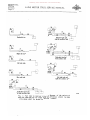
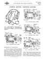
Circuit Nos, 28 to 31, inclusive, each per
tain to fuel tank-to-receiver unit circuits.
Because of the variety of possible combinations
for these hook-ups, reference should be made
to the illustrations for proper connection of
cables, (Fig. 1)
13. Magneto ground.
Circuit Diagrams
Wiring circuit diagrams are illustrated in
the owner's and driver's manuals and in the
service manuals. With each of these illustraPRINTED IN UNITED STATES OF AMERICA
12. Ignition switch to ignition coil (or booster
switch to booster coil).
14, Magnetic starting motor switch to push
button switch to feed.
15. Main light switch feed.
16. Light switch (HT) to service headlight or
dimmer switch.
17. Dimmer switch to upper beam and to beam
indicator.
18. Dimmer switch to lower beaIl'l.
Donated by John & Susan Hansen - For Personal Use Only
ELECTRICAL
SYSTEM
Section A
Page 2
L-LINE MOTOR TRUCK SERVICE MANUAL
19. Light switch (Bod) to blackout driving lamp.
including resistor.
46. 12 - Volt radio
master switch).
20. Light switch (BHT) to parking lamps or
marker light.
47. Slip ring feed.
circuit
(including
radio
48. 24 Volt radio feed.
21. Light switch (R) or (HT) on blackout switch
to service tail light.
22. Light switch (H) or (S) on blackout switch
to service stop light.
49. Receptacle. Auxiliary power outlet, posi
tive lead.
50. Receptacle, Auxiliary power outlet, nega
tive lead.
23. Light switch (BS) to blackout stop light.
51.
24. Light switch (BHT) to blackout tail light.
25·. Horn switch (including feed) to horn (or
horn relay).
52. 6-Volt tap on taillight dropping resistor to
tail light.
53. Electric brake control circuit.
26. Horn relay feed and horn relay to horn.
54. Fuel cut-off circuit.
27. Instruments feed (instruments with polar
ity).
55. Flame primer low tension circuit.
56. Flame primer high tension circuit.
28.
29. Fuel gauge sender to receiver -
30. See illustrations Figure 1.
57. Instrument panel ground.
58. Compass light circuit.
59. Cab (or hull) ventilating fan circuit.
31.
60.
32. Oil level gauge sender to receiver.
33. Water (and oil) temperature gauge sender
to receive r.
34. Low engine oil pressure warning light cir
cuit (including feed).
35. High water temperature warning light cir
cuit (including feed).
36. Oil pressure gauge sender to receiver.
61. Auxiliary generator field.
62. Auxiliary generator armature.
63. Auxiliary generator ground.
64. Auxiliary generator regulator to battery
(including heater transfer switch).
65. Auxiliary generator starter relay circuit
(including switch and feed).
37. Outlet socket or junction block.
66. Auxiliary generator starter to transfer
switch (including starter or relay).
38. Dome light circuit (including breaker and
switch).
67. Emergency stop switch ground.
39. Map light circuit.
68. Battery interconnecting cables.
40. Instrument light circuit.
69. Resistor to ground
coupling.
41. Starting motor to battery (-) (series paral
lel switch hook-up).
70. Regulator ground.
42. Series parallel switch (B+) to. battery (+).
71. Windshield wiper ci rcuit.
43. Series parallel switch (A-) to battery (-).
72. Low transmission oil pressure indicator,
circuit, with feed.
44. Series parallel switch to ground.
45. Series parallel switch
motor.
(B-) to starting
terminal on trailer
73. Radio terminal box to ground.
74. Series parallel switch to solenoid relay.
Donated by John & Susan Hansen - For Personal Use Only
ELECTRICAL
SYSTEM
Section A
Page 3
L-UNE MOTOR TRUCK SERVlCE MANUAL
75. Stop switch circuit (SW to SS on blackout
SW).
100. Tachometer transmitter to ground.
101. Defroster
switch
including feed.
76. Fuel pump control feed.
77. Fuel pump switch to fuel pump (left side).
to
defroster
motor
102. Heater switch to heater motor including
feed.
78. Fuel pump switch to fuel pump (right side).
103. Cigar lighter.
79. Fuel gauge sender ground.
104. Fog light switch to fog light including feed.
80. Ignition coil to distributor.
105. Tractor light (Back-up).
81. Battery to starting motor switch (or term.
block) including master switch.
82. Starting motor switch (or term. block) to
starting motor.
106. Carburetor idle fuel shut-off valve.
107. Marker or identification light circuit.
108. Clearance light circuit.
83. Blackout light switch (TT) to tail connec
tion on trailer receptacle.
109. Mico brake lock circuit.
34. Blackout light switch (SS) to stop light con
nection on trailer receptacle.
110. Fuell gauge switch (C) to ground
safety tanks).
85. Low air pressure indicator buzzer (or
light).
Ill. Lockoff solenoid valve to switch (including
feed).
86. Ground on series parallel switch to am
meter (including circuit breaker).
112.Auxiliary ammeter to ground-negative.
(dual
87. Spotlight circuit for trucks and wreckers.
113. 6- Volt radio circuit (including ratio master
switch).
88. Winch torque limiter control.
114. Direction signal, left turn-front.
89. Automatic choke.
115. Direction signal, left turn-rear.
90. Trailer receptacle to ground.
116. Direction signal, right turn-front.
91. Headlight to ground.
117. Direction signal, right turn-rear.
92. Parking light to ground.
118. Direction signal, feed circuit.
93. Starting motor relay to ground.
119. Voltage divider ground.
94. Starting motor relay auxiliary grounding
circuit.
120. Voltage divider feed or instrument resis
tor feed.
95. Tail light to ground.
121.
96. Speedometer sender feed.
122. Overdrive relay to overdrive governor
(including kickdown and overdrive switch).
Overdriv~
relay to ignition switch.
97. Tachometer transmitter feed.
98. Tachometer transmitter
tachometer positi~e (+).
positive (+) to
99. Tachometer transmitter negative (-) to
tachometer negative (-).
f'~IN1'£D
IN UNITED STATES OF' AMt"RlcA
123. Overdrive solenoid to ignition coil (includ
ing kickdown switch).
124. Overdrive solenoid to battery (including
relay feed).
Donated by John & Susan Hansen - For Personal Use Only
ELECTRICAL
SYSTEM
Section A
Page 4
L-UNE MOTOR TRUCK SERVICE MANUAL
30
30
30
29
Underskirt tank
[?
Underskirt tank and
right side auxiliary tank
~
J
29 Right side tank
28
~
28
~
D
31
Left side tank and
right side auxiliary tank
Rear end tank
30
gauge
switch
30
!29 Underskirt tank and
dual auxiliary tanks
Left side tank
~.
30
29
0Rec.
30
28
,30
28
Underskirt tank and left side auxiliary tank Fig. I - Fuel tank to receiver circuits. Because of the variety of
possible combinations for these hook-ups, reference should be made
to the above chart for proper connection of cables.
A-22921
Donated by John & Susan Hansen - For Personal Use Only
~
Fuel gauge sender unit
®
14
8
8
6
12
11
8
14
14
14
16
16
17
17
14
10
12
12
14
17
16
18
18
14
16
20
20
21
22
26
14
16
14
14
26
12
27
27
29
14
16
16
16
16
16
16
14
14
I
"z
®
C
z
:;
~
m
~
1
E
'1
~
·•
Generator
/@ "
~
,, @
~
~
ii
1
2
4
~r
•
~
_
Circuit
No. or Cable
Index Gauge
Letter
I
4ga. Engine
/-@ }§
1':~!:/16ga.
Starting
motor
' '."f®
®
--, Junction block Oil light 30
33
36
40
71
80
91
light
®
/@ J/~@llJ@
JJ~~~~v'III6'" I,,-~-;~ 10
A
14
16
B
C
D
E
F
0
3
12
0
16
G
H
14
14
16
16
J
P
Cabl.Color
or
Description
Generator field
Generator arm
Regulator to am·
meter
Ammeterf_d
Ignition switch feed
Ignition switch to ig
nition coil
Startinq
Light switch f ....d
Dimmer switch f.ed
Hiqh beam feed
High beam h ..ad·
li;tht lead..
Hig beam indiea·
tor
Low beam f..ed
Low b .. am h .. ad·
li~htl"ad..
P .... ing feed
Parking light lead.
Taillight
Stop light
Horn and stop light
feed Horn !lind horn relay fseds
Inlltrument feed
Instrument feed
Fuel gauge
Fualgauge
Temperature gauge
Oil pressure gauge
Instrument light..
Wiper switch feed
Ignition coil to di.,...
tributor
Headlight ground
Natural with circuit
letter "A" or black
Battery ground
Engine ground
Cab ground
Battery cable
Natural with circuit
letter uF" or red
Instrument
bar
Horn push button
Fuel gauge ground
Natural with circuit
Jetter "p" or ~n
x""]
~
Fuel gauge sender unit
bUB
d..,Sto p
~
tz
[T1
$
o
-J
o
:::0
-J
:::0
C
o
7':
(J)
~
<
(=)
[T1
$
»z
c
»
r
Enlarged
view X-X
CD M
l'
M
Ul
0
roUlt-J
~Regulator
8-4737
Fig. 2 - Circuit Diagram - L-IIO Series to L-IBO Series inclusive (Hot "Metro") r
'O~>-<!!:d
Pl ..... Ul ......
OllOt-JO
ro::lM>
<.}'I>-~l'
Donated by John & Susan Hansen - For Personal Use Only
't1CflCflM
Il>(l)O-<t""
()QOCfl
(l)~!-:JM
o ..... ()
'-J !-:J
O'-;l
>:;:;::
()
>
t""
r
t
z
[T1
$::
~
o
:::0
-1
:::0
C
(")
~
CJ)
[T1
:::0
<
(")
[T1
sender unit
Battery ground strap/
//
$::
/
Junction block /
»z
- - - ---Stop light switch
Magnetic starting switch
"'--
"'-,,-
c
»
r
Horn relay
Head light
8-4696
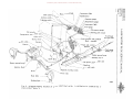
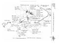
Fig. 3 - Diagram showing location of various electrical units.
clusive (Hot "Metro").
l-IIO Series to l-J80 Series in
Donated by John & Susan Hansen - For Personal Use Only
Circuitj
No, or Cabl.. Ind..x Gauge
Letter'
Fuelgualle sender un~@:
(])
4 or H\
,,
z
;:
"z
c
z
:;
"m"
~
\
fl.-''---,-'
I
I I
=
I \
®@®®
Generator
\
3 or T\ \
2 or
@
p\\ \\ "f'1
~
Windshield
wiper motor
Junction block
~
)1)
•
~
";;
8
14
14
14
15
16
14
10
12
12
14
17
17
17
16
18
18
14
16
20
20
21
22
26
14
16
14
14
10
26
12
27
27
28
29
33
36
14
16
16
16
16
16
16
14
14
\Circuit
breaker
,0
•
5
11
12
\
~
co
o~
14
8
8
1 or Bat \ \[\1
14 ~a 16 ga, 16 ga,
~
1
2
4
Distributor
I
I
1
40
I
"
Instrument
\
light
T ach'ometer
Enl:ine I:round
I
71
80
91
A
14
16
B
C
D
0
3
12
E
~
Dimmer
switch
Circuit breaker
and terminal block
assembly------
I
I
c!.!'
F
1~
G
H
,J
P
14
14
16
16
Cabl.. Color
or D..cription
Generator field
Generator arm
ReGulator to am ..
meter
Ammeterf.ed
Ignition switch fe.d
Ignlllon switch to ig
nition coil
Starling
Light ;'witch f.ed
Dimmer switch fe.d
High beam f...d
High beam h.ad
lJ.~ht l.ad.
Hig beam indic.·
tor
Low b.am fe.d
Low b.am h.ad
l!~ht I..ad.
Par ing feed
Parking light l.ads
Taillight
Stop light
Horn and stop light
f .... d
Horn and horn ...~
lay f.eds
Instrument feed
Instrument f .... d
Fu.lgauq.
Fu.lgauqe
Temperature qauQ.
Oil pre••u... 9au9.
Instrument light.
Wiper switch fe.d
Ignition coil to dis
tributor
Hsadlight~ound
Natural wi circuit
letter"A" or black
Batt.ry ground
Engine ground
Ca qround
Battary cable
Natural with circuit
l.tter "F" or red
lnatrument bu. bar
Horn puah button
Fuel gauge qround
Natural with circuit
I_tter "P" or qre,_n
Junction block
14 ga, 16 ga,
&6l
14 ga,
~ ~~~1 ~
I 1\
I
I
I
I
I
,
1\
1
I
$:
0
~
0
:;u
~
:;u
C
0
A
en
[T1
:;u
<
0
[T1
$:
X
Tail Stop
»
r
~
1--1
Z
[T1
»
z
~R
X"I \
Horn'K' 12
.
r
r
c
Enlarged
view X'X
"l'
14 p.
Regulator
Fig.
~
- Circuit Diagram - l-190 Series And Up.
.......
M
t:"'
M
O
roUlUl >-l
'U ;?"< ::0
III ..... Ul .....
OQo>-lO
ro::lM::t>
-.I::t>~t"'
Donated by John & Susan Hansen - For Personal Use Only
't1
tJltJl M
1l)(1)t«4t"
OQOtJl
Windshield wiper motor
\\
Dash panel
\
\
·
CIgar
\
I
I
--
/
.
.
.I
.
I
f
I
///
J
-
I
Temperature gauge
sender unit--.....l
.~
/"
-Fuel /
gauge
.
___ Oil pressure gauge
///
___//
~/-;//
'~ __ --
I1
\
\
,'"
\\
. ~\
~,/~
.
,I
\ - --~--Starting
push switch
\\
~J-.
'\'
...... Dome lIght
Instrument lights
\Voltage and current regulator
.
I
I~~ Ignition coil----J
s:
I
I
;0
I
I
Fuel gauge {ender unit
(L. H. tank)
/
/
~,
'- "
"
Generator
Engine ground strap- ,
;0
n<
[Tl
s:
»
z
c
»
r
1
\
\
I
\
I •
C
7:::
n
[Tl
~{d~IV
I
~;:'''\
• • • •/ '
--l
;0
{j)
_--Battery
~ ~.\~l~~~--~----Battery cable
~n
tz
o
--l
o
I
_---Battery ground strap
~I~.
/1@;>
IVI j : / \.('" ~J
~', ,I .~ /;:J'e
/
r
[Tl
\\Circuit breaker and terminal
'.\
block assembly
,.1111 Ii
~
.
~~-'..:.."---Tachometer
~
.
I -- , ---1
"- ,/,..-/'
Cab ground strap-----...... --Junction block\
/
I - fI
- . ,- ----- I
.--
Light swltch----..2>·. I _-->~ ~
Beam indicator light~
>-
()
. .
To tatlltght
f) Ammeter gauge
. ,~. and stop light
If!
// Temperature gauge
~"'~.
\
j.
-
>~~
',"~~... ~ '-"
"I(,l'~
I ,Speedometer
II
I,,,
Pi
'~
oogM~
'", <.~
,
I
Ignition switch___
m::t.~~
Windshield wiper switch
_-Fuel gauge sender unit
/, Instrument light
~~
(R. H. tank)
I
•
/
'-....Y"
"
\ Stop light sWitch
\ Oil pressure gauge "' . . . " \ 0 '
't 1
'
"
llunler SWI c 1
\
'" "
sen d er unit
\\J unctIOn
.
bl oc k
"'", . . .'''Magnetic
starting switch
,
. . . Startmg
. motor
' ht
H eadlIg
/ Parking light
8-4868
Fig. 5 - Diagram showing location of various electrical units - L-190 And Up.
Donated by John & Susan Hansen - For Personal Use Only
ELECTRICAL
SYSTEM
Section B
Page 1
L-LINE MOTOR TRUCK SERVICE MANUAL
BATTERY
Storage Battery Equipment
Present production trucks are equipped
with Auto-Lite batteries.
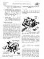
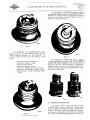
Code Dating
Each Auto-Lite Battery bears a shipping
code stamped on one button of one cell connec
tor of the battery. This button is indicated as
nA" in Fig. 1.
;-----+- Button-A
o
-i---...".
o
000
e
(IT)
Standard assembly
e
Reversed assembly
00:=--=00
0
center cell
6-volt assembly.
A-16015
Fig. I
I
1
2
3
4
5
6
7
8
9
10
11
12
Year
Symbol
Year
1949
1950
1951
1952
1953
1954
1955
1956
1957
1958
!
9
0
1
2
3
4
5
6
7
8
The specific gravity of the electrolyte
(distilled water and acid solution) must be
maintained at 1.225 to 1.250 and the level of the
solution should be at the star level in cell cov
ers. A fully charged battery has a specific
gravity of 1.280-1.290 at 80 degrees (F.).
To eliminate the possibility of harmful
sulfation of plates, a battery with a specific'
gravity of 1,225 or less should be recharged to
1.280-1.290 at 80 degrees (F.) battery temper
ature.
r-"
I
L • .J
I
The following chart shows the effect of
atmospheric temperature on the capacity of a
battery:
r-'I
I
,__ ...t
Month
January
February
March
April
May
June
July
August
September
October
November
December
Month
Symbol
Atmospheric Temperature Affects Battery
Capacity
Positive button - cell adjacent to
positive terminal cell- ll-volt assembly.
i
Month
$
End to .end assembly
Positive button
The following chart is the key to the code
datings found on Auto-Lite batteries used in
International Motor Trucks of later manufac
ture:
Year
A-.23439
Fi g. 2
The code date will 'be found stamped on the
positive connecter button on the cell adjacent
to the positive terminal cell. See Fig. 2,
In the first row are two symbols: the
first is the month, the second is the year of
shipment, for example - "8-9" which decodes
August - 1949.
In the third row, the second space is used
to indicate whether the battery was built "dry"
or 'wet." If there is no symbol in the space
the battery was built wet. If the space contains
a letter "yn - the unit was built dry. If the
letter "Y" is encircled thus - ®the battery was
built dry and made wet before shipment.
PRINTEO iN UNfTED STATES OF AMERICA
State of
Charge
Full
Full
Full
Full
Full
Full
Percentage
Capacity
Temperature (F.)
80 degrees above 0
0
60 degrees above 0 0
o
40 degree s above 0
0
20 degrees above 0
Zero degrees
o
20 degrees below 0
100
88
75
62
45
20
Specific Gravity Affects Freezing Point of
Electrolyte
Specific gravity of the electrolyte deter
mines the temperature at which a battery will
be harmed or damaged by freezing.
Donated by John & Susan Hansen - For Personal Use Only
ELECTRICAL
SYSTEM
Section B
Page 2
L-UNE MOTOR TRUCK SERVICE MANUAL
The following chart gives the freezing
point of battery electrolyte at given specific
gravities:
Electrolyte
Specific
Gravity
Freezing
Point (F.)
1.280
1.220
1.210
90 degrees below 0
I
o
30 degrees below 0 0
20 degrees below 0
1.100 20 degrees above 0
1.000
32 degrees above 0
o
o
the specific gravity readings of each cell, date
of delivery, truck model and chassis serial
number, and the name of the purchaser. The
card will then be filed in a manner similar to
the Customer's Record Card. If the battery is
delivered in a truck being transferred
in
another District, the battery record card shall
accompany the battery and shall be continued
by the receiving branch.
Battery Maintenance
The Ft. Wayne and Springfield factories
are exercising every care in the handling and
rotation of batteries to assure the delivery of
a fresh and fully charged battery with each and
every truck delivered to the territory.
The territory must also follow this prac
tice of rotation, using the oldest batteries first
as determined by the code datings stamped on
the center cell connector button.
o
Battery Record Card, Form CTS-7
The Form CTS-7 Battery Record Card is
the record or history of each battery received
and shipped. The card has spaces provided for
allnecessary information pertaining to the bat
tery. One of these record cards must be main
tained for each battery and it should reveal the
complete history of the unit while in your pos
session.
Upon receipt of a shipment of trucks from
one of the factories or from another Branch,
the batteries must be removed immediately and
battery record cards filled out for each battery.
THERE MUST BE NO DEVIATION FROM
THIS PRAC TICE.
The date received, battery type, code
marking, truck model, and chassis serial num
ber must be entered on a separate record card
for each battery.
The specific gravity of each cell must be
recorded on the card under TEST RECORD.
The date and the inspectorrs initials should
also be shown in the space provided. Any bat
tery showing a specific gravity reading of less
than 1.225 must be placed on the charging line
and brought up to 1.280-1.290 at 80 degrees
(F.) (battery temperature).
Subsequent inspections of the battery shall
be made every thirty days and the specific
gravity readings recorded, and distilled water
added if necessary. This procedUre shall fol
low during the stay of the battery in your stock.
Upon delivery of battery in a truck, the
record card shall be completed by recording
To facilitate truck movement in and around
the District or Warehouse, a service battery
should be prepared having long cables and clip
ends.
Battery Recharging
Suitable and adequate equipment for battery
charging is available through the Motor Truck
Service Section, Chicago Office.
_
The general procedure in battery charging is as outlined: 1. With vent plugs in place, wash the top of
the battery if necessary, using a solution
of water and common baking soda. Rinse
with clear water.
2. Remove vent plugs from each cell.
3. Fill the battery cells with pure distilled
water to star level in cell covers.
4.
Connect battery to the charger unit in
series, connecting the
terminal
outlet from the supply
positive
of the first battery. Connect
.-=--"'-_-.. terminal of the first battery
terminal of the second
so on through the number of
batteries being charged. (Do not attempt
to exceed the capacity of the battery
charging equipment in the number of
batteries to be charged at one and the
same time.) The last battery m.ust have
its negative terminal connected to the
negative outlet of the charging unit.
5. Adjust the charging rate in amperes to the
lowest normal charge rate of~.tl(!~E:1allest
size battery according to the following
chart.
Donated by John & Susan Hansen - For Personal Use Only
L-UNE MOTOR TRUCK SERVICE MANUAL
Batteries should remain on charge for a
period of time sufficient to obtain normal volt
age and specific gravity readings of each cell.
The required length of time will vary from 12
to 48 hours, depending upon the state of dis
charge of the battery at the time it was placed
on the charging line.
Type of Battery
Volts
2H-I05, 2H-I05R
2H-120, 2H-120R
2H-135R
3H-136R
4H-152R
I
8T-200
6
6
6
6
6
12
Normal
Charge
Rate
No. of
Plates
15
17
19
17
19
25
7
8
I 9
8
9
12
Amperes
Amperes
Amperes
Amperes
Amperes
Amperes
Temperature readings should be taken
frequently to prevent the electrolyte tempera
ture exceeding 110 degrees (F.) at any time.
Should the temperature rise higher than 110
degrees (F.), the charging should be discontin
ued and the electrolyte allowed to cool. The
charging of the battery may then, and only then,
be continued.
6. Cell voltage is determined by a normal
electrolyte temperature of 80 degrees (F.).
Voltage readings are to be taken while the
battery is on charge at the normal rate as
specified in the foregoing chart.
The cell voltage of a fully charged battery
on charge at the normal rate should read as
follows:
Temp.
80 degrees (F.) - Voltage between 2.5
and 2.6 volts
Temp. 100 degrees (F.) - Voltage between 2.4
and 2.6 volts
Temp. 11 0 degrees (F.) - Voltage between 2.35
and 2.55 volts
A battery is fully charged when the cell
voltage values are as shown in above table and
there is no further rise in voltage over a period
of two hours.
7. Add
water as necessary,
disconnect
batteries from the charging line, replace
vent plugs, wash the tops of the batteries,
and place in attachment room.
Excessive Evaporation of Electrolyte Indicates
Overcharging
When excessive evaporation of the elec
trolyte is experienced, you may be sure that it
is an indication that the battery is being over
charged.
Necessity for too frequent battery re
charging may indicate that the battery is.being
undercharged.
P~'NTED
IN UNITED STAT£S OF AMERICA
ELECTRICAL
SYSTEM
Section B
Page 3
Battery Not to Blame for Failure When Conditions Adverse It has been shown that temperature plays
an important part in affecting the capacity of a
battery, and that the colder the temperature
the lower the battery capacity. Bearing this in
mind, it will be seen that a fully charged battery
is only partially capable at subzero tempera
tures. This fact, coupled with the condition in
which many engines are found, brings about
complaints regarding the size, quality, and
construction of the standard equipment battery.
There are times when it is necessary to
increase the size of the battery or starting
motor, but such action should not be considered
a "cure-all" for hard starting complaints during
winter months. Even when special equipment
of this nature is installed, it is still essential
to:
1. Use a lubricating oil with the correct body
for Winter Service.
2. Maintain distributer points in good condi
tion and properly spaced.
3. Have clean and properly spaced spark plug
electrodes.
4. Have good compression in the engine.
5. Maintain all joints and connections between
the carburetor, manifolds, and engine in a
gas-tight condition.
6. Ascertain that the carburetor choke valve
is operating properly.
7. Determine that the engine is well grounded
and that the ground straps are
fastened to
contacts.
Battery Warranties and Manufacturers!
Policy
Storage batteries used in International
Motor Trucks are limited to a free repair or
replacement warranty of 90 days against defec
tive material and workmanship, beginning on
the date the battery is placed in service.
In accordance with this arrangement,
service adjustments after 90 days are based on
miles of service or
- which
ever occurs first.
tioned for there are
a customer
will attain the limit of miles of service prior
to the time limit set forth. In such cases, the
adjustment will be made on the :miles of service
and not on the time limit.
Auto-Lite Batteries, whether installed as
factory equipment by the Inte rnational Har
vester Company or sold as replacements to
Donated by John & Susan Hansen - For Personal Use Only
ELECTRICAL
SYSTEM
Section B
Page 4
L-UNE MOTOR TRUCK SERVICE MANUAL
International Harvester Truck owners,
subject to adjustment as outlined below.
are
Factory equipment or replacement bat
teries are adjusted according to the following
table:
Service Adjustment Chart
Battery
Equipment
Type
2H-l05,2H-105R
2H-120,2H-lZOR
2H-135R
3H-136R 4H-!52R
8T-ZOO
I
i
I·
Mileage
Adjustment.
Time
Adjustment
15,000
18,000
21,000
18,000
18 000
24,000
7-1/2 Months
9 Months
10-112 Months
9 Months
9 Months
8 Months
Complaints on Battery Performance
Any complaints pertaining to battery per
formance should be referred to the nearest
Auto-Lite Service Station.
Complaints on Service Facilities
Complaints on service facilities of Auto
Lite distributors must be referred to the Sales
Department, Motor Truck Service Division,
Chicago Office. Accompany complaint with all
details concerning the battery and the truck
from which it was removed. The matter will
be handled with the manufacturer from the
Chicago Office and not by the District direct.
Batteries Older Than Four Months at Time of Delivery Motor Truck Service Bulletin No. 82, 1931,
pertained to batteries which were on hand and
which were older than four months according
to code dating. :That bulletin advised that these
batteries shoula' be delivered in proper rotation
but that they should be properly identified by
stamping the letters "IHCII on the center ce1l
connector button. Battery Record Cards, Form
C TS-7, were to be notated with this information.
Customer Record Cards were to bear a nota
tion to the effect that the battery was past the
four months' code dating.
PROPER AND CONSISTENT ROTATION
OF BATTERIES IN STOCK MUST BE FOL
LOWED, AND THE OLDEST BATTERIES
ACCORDING TO CODE DA TINGS DELIVERED
FIRST.
Strict Adherence to Instructions Necessary
All persons who have occasion to handle
batteries or battery transactions should thor
oughlyfamiliarize themselves with the instruc
tions pertaining to maintenance of batteries,
withbattery warranties, and the manufacturer's
policy. There should be no departure from the
instructions as outlined.
It must be remembered that while the
manufacturer is under certain obligations in
accordance with the warranty policy of the
batteries, we too, are not absolved of obligation
to the manufacturer to do our part of the
arrangement and policy.
It is felt that of all the instructions outlined
herein that the fo1lowing are the most impor
tant and no excuse can be accepted for depar
ture from them:
1. REMOVAL OF ALL BATTERIES FROM
THE TRUCKS AT THE TIME THEY ~~.RE
RECEIVED AT THE BRANCH,
AND
KEEPING THEM IN THE ATTACHMENT
ROOM OR BATTERY ROOM UNTIL' THE
TIME OF DELIVERY.
2. INSPECTION OF BATTERIES EVERY
THIR TY
DAYS,
AND
MAINT AINING
THEM AT THE PROPER WATER LEVEL
AND AT THE PROPER SPECIFIC GRAV
ITY READINGS.
3. KEEPING OF FULL AND COMPLETE
RECORDS OF THE BATTERY ON THE
BATTERY RECORD CARD, FORM CTS-7.
4. PROPER AND CONSISTENT ROTATION
OF BATTERIES IN STOCK, DELIVERING
THE OLDEST BATTERIES FIRST.
5. INSTRUCTIONS TO THE CUSTOMERS
IN THE PROPER CARE OF THE BAT
TERY AND A CAREFUL STUDY OF
THE REQUIREMENTS ON THE BATTERY
AND CORREC TIONS FOR SAME IN THE
CUSTOMER'S TRUCK.
General Instructions
Do not add anything other than distilled
water or drinking water which is colorless,
tasteless, and odorless to a storage battery.
The use of patent electrolytes or battery IIdopes ll
are injurious and void the guarantee.
Use a strong solution of soda and hot water
for removing terminal corrosion and cleaning
the battery. To prevent corrosion apply vase
line or cup grease to the terminals.
Moist Uncharged Storage Batteries
To prepare a battery for service which has
been shipped dry, all cells should be filled to
3/8" above the tops of the spacers with the
electrolyte specific gravity of 1.345.
CAUTION!
NEVER POUR WATER INTO SULPHURIC
ACID.
Donated by John & Susan Hansen - For Personal Use Only
L-UNE MOTOR TRUCK SERVICE MA:.lUAL
Important Instructions
To prepare 1.345. specific gravity electro
lyte from full-strength sulphuric acid stir con
stantly while adding one volume of 1.835 acid
to two volumes of water.
THIS MUST BE
DONE VERY SLOWLY AS A GREAT DEAL
OF HEAT IS GENERATED.
Use only glass or earthenware containers
for storing and for mixing the acid.
In some localities acid can be purchased
already mixed to 1.345 specific gravity.
Table 1
Cold Climate
Warm or Tropical
Climate
Filling
Acid
Final
Adjustment
Filling
Acid
Final
Adjustment
Sp. BauGr. me
Sp. BauGr.
me
Sp. Bau,
Gr.
me
Sp. Bau,
Gr.
me
1.290 31.5 1.245 28.5
1.225 26.4
1.345
3.7
A tropical climate is that in which the
temperature never falls below the freezing
point of water (32 0 F.) (00 C.).
Place the battery on charge at the ampere
rate given below:
Battery Equipment
Type
2H-I05R
2H-120R
2H-135R
3H-136R
4H-152R
8T ·200
Ampere
7
8
9
8
9
12
For converting dry batteries to wet, use a
constant rate charger. Do not use a constant
potential charger.
The total initial charge must be for 52
hours.
However, should the temperature of the
electrolyte while on charge reach ll5° F.
0
(46 C.). discontinue the charge and allow the
battery to cool. Then resume charging.
The electrolyte at the end of 52 hours'
charge with battery temperature at 80 0 F.
(26.7 0 C.) should be at the value given in
Table 1. Make corrections for temperature,
when necessary, according to previous direcPAINTED IN UNITED $TATES OF AM£'IIJICA
ELECTRICAL
SYSTEM
Section B
Page 5
tions. Adjust electrolyte specific gravity by
adding distilled water to weaken and 1.400 spe
cific gravity acid to strengthen.
When adjusting electrolyte, charge the
battery for one hour before' taking a final
reading. At the end of 52 hours the cell voltage
of the battery while on charge at the proper
rate should be between 2.5 and 2,7 volts at
80 0 F.
Replace vent plugs, wash externally to
remove traces of acid. and dry. Battery is
now ready for service.
INSTALLA TION OF CABLES
When making replacement of original bat
tery cables, starting motor cables or other
wires utilizing protective loom or grommets.
it is essential that the service cable be equipped
with the same type loom or grommet protection
as was removed on the replaced cable or wire.
Cables that are replaced without proper loom
protection create a fire hazard. The wiring
circuits on new vehicles are closely checked
and approved by Underwriter Companies, there
fore. the original circuits should be maintained
both as to location and protective devices.
The loom or grommet is placed on cables
for the purpose of safeguarding against chafing
or cutting through the insulation at points where
the cables contact the chassis.
When replacing cables on custome rs trucks
or when making sales of cables, make certain
that protective loom or proper grommets are
provided where required.
The storage battery can deliver only what
the battery cables are able to carry to the elec
trical system. The battery cannot operate effi
ciently if it has to overcome the resistance of a
worn-out, corroded or undersize cable. Faulty
battery performance may indicate cable trouble.
Care should be taken when installing a ca
ble terminal. It should never be hammered into
place. To do so may drive some of the active
material from the battery plates into the bottom
of the battery container or crack the cell cover.
Also some metal may be sheared from the post,
making it too small for good contact when the
next replacement is necessary. The best prac-.
tice is to pry the jaws of the terminal apart be
fore slipping it over the post.
Donated by John & Susan Hansen - For Personal Use Only
Donated by John & Susan Hansen - For Personal Use Only
L-LINE MOTOR TRUCK SERVICE MANUAL
ELECTRICAL
SYSTEM
Section C
Page 1
IGNITION COILS Sealing nipple
High tension
terminal
Sealing-==:....:....~tc!.
gaskets
A-22612
Fig. I - Schematic wIring diagramofthe primary
circuit of an ignition system.
Coil ..,,"4'-....::,
DELCO-REMY MODEL 1115327 IGNITION COIL The Delco-Remy (Model 1115327) Ignition
Coil is oil-filled and hermetically sealed to
prevent the entrance of moisture
The high
tension terminal is protected by a bakelite in
sulator which has high resistance to leakage
across its surface andis not damaged by leakage
which might occur. The coil should be mounted
vertically with the high tension terminalddown
or horizontally with primary terminals in same
horizontal plane. Make sure the coil is mounted
so the case is grounded and that the leads are
tightly connected to the coil terminals.
If the coil is defective it must be replaced.
since the coil can not be repaired. But before
a coil is discarded, it should be carefully
checked on a good te ster to determine that it
is actually defective.
Construction and Operation
The ignition coil is a pulse transformer
that transforms or
":up the low battery or
generator voltage to the high voltage necessary
to jump the gaps at the spark plugs in the en
gine cylinders. This voltage may reach as
much as 20,000 volts.
The ignition coil contains three essential
parts; a primary winding consisting of a few
hundred turns of relatively heavy wire, a sec
ondary winding consisting of many thousand
PRINTED IN UNtTEO STATES OF" AMERICA
A-22552
Fig. 2 - Cutaway view of oil filled coil.
turns of very fine wire, and laminated soft iron
which serves to concentrate the magnetic field.
The primary winding is assembled around the
outside of the secondary winding, and the lam
inated iron is distributed so that one portion
serves as a core for the windings and the re
mainder as'a shell around the entire subassem
bly. This subassembly is then placed in the
coil case and the remaining space nearly filled
with insulating compound or oil, and the coil
cap assembled into place.
Fig. 3 illustrates a heavy-duty ignition
coil used on motor-coach, truck and marine
applications. This coil also is hermetically
sealed against the entrance of ai r 0 r moisture
and is oil filled for greater insulation protec
tion. The fins cast in the one-piece case plus
the oil filling permits improved heat radiation
which is a factor in efficient ignition coil per
formance.
Donated by John & Susan Hansen - For Personal Use Only
ELECTRICAL
SYSTEM
Section C
Page 2
L-UNE MOTOR TRUCK SERVICE MANUAL
High tension terminal
Coil Service
Ignition coils do not normally require any
service except to keep all terminals and con
nections clean and tight. In addition, the coil
should be kept reasonable clean, but it must not
be subjected to stearn cleaning or similar
cleaning methods which may cause moisture to
enter the coil unless it is of the hermetically
sealed type. Rubber nipples on the high voltage
terminals are valuable in preventing Ittracingtl
or leakage of current across exposed surfaces.
If poor ignition performance is obtained
and the coil is suspected of being the cause, the
coil may be tested on the truck or it may be
removed for the test.
Coil
winding
Fig. 3 - Cutaway view of heavy duty oil-filled
colI. Coil case utilizes fins to aid in cool jng
for better ign it ion col I performance.
Donated by John & Susan Hansen - For Personal Use Only
L-UNE MOTOR TRUCK SERVICE MANUAL
ELECTRICAL
SYSTEM
Section D
1
DISTRIBUTORS Rotor
Cap
Terminal
Breaker cam
A-226J8
Fig. 2 - Sectional view of distributor.
Fig. I - Ignition system circuit.
lationship of various units.
Showing re
IGNITION DISTRIBUTORS
The ignition systeITl (Fig. l) consists of the
ignition coil, condenser, ignition distributor,
ignition switch, low and high tension wiring,
spark plugs, and a source of electrical energy
(battery or generator).
The ignition systeITl has the function of
producing high voltage surges and directing
theITl to the spark plugs in the engine cylinders.
The sparks ITlust be tiITled to appear at the plugs
at the correct instant near the end of the COITl
pression stroke with relation to piston position.
The spark ignites the fuel-air ITlixture under
cOITlpression so that the power stroke follows
in the engine.
distributor directs the high voltage surge
through the distributor rotor, cap and high ten
sion wiring to the spark plug which is ready to
fire.
There are thus two separate circuits
through the ignition distributor. One of these
is the priITlary circuit which includes the dis
tributor contact points and condenser. The
other is the secondary or high tension circuit
which includes the distributor cap and rotor.
DELCO-REMY DISTRIBUTOR
The Delco-ReITlY Distributors used on BD
and RD engines are full autoITlatic units with
centrifugal advance ITlechanisITl. The SD engine
uses a distributor having the vacuuITl-autoITlatic
ITlechanisITl.
Function of Distributor
The distributor has three jobs. First, it
opens and closes the low tension circuit between
the source of electrical energy and the ignition
coil so that the priITlary winding is supplied
with interITlittent surges of current. Each surge
of current builds up a ITlagnetic field in the coil.
The distributor then opens its circuit so that
the ITlagnetic field will collapse and cause the
coil to produce a high voltage surge. The
second job that the distributor has is to tiITle
these surges with regard to the engine require
ITlents. This is accoITlplished by the centrifugal
and vaCUUITl advance ITlechanisITl. Third, the
PRINTED IN UNITED STATES Of' AMIi:RfCA
Fig. 3 - Full automatic distributor.
moved.
Cover re
ELECTRICAL
SYSTEM
Section D
Page 2
Donated by John & Susan Hansen - For Personal Use Only
L-UNE MOTOR TRUCK SERVICE MANUAL
Distributor Maintenance
LUBRICATION - Do not remove pipe plug
in distributor oil reservoir.
This reservoir
back of the shaft bushing is filled with light
engine oil and sealed before the unit is shipped.
The supply of oil is sufficient to last for 25,000
miles of operation under normal conditions.
Thus the plug need not be removed oftener than
every 25,000 miles (or at time of overhaul) for
lubrication except when unusual heat or other
operating conditions are experienced. Grade
SAE #20 oil should be added when needed. Seal
the plug with sealing compound that will hold
against oil.
A trace of high melting point ball-bearing
grease should be placed on the breaker cam
every 1000 miles. Every 5000 miles put one
drop of light engine oil on the breaker lever
pivot and a few drops on the felt wick under the
rotor.
Inspection
The cap should be removed at regular in
tervals and the contact points, rotor, and cap
examined. Check the high tension wiring for
frayed or damaged insulation and poor connec
tionsat the cap or plugs. Replace if necessary.
Replace the cap or rotor if they are cracked or
show carbonized paths indicating the secondary
current is leaking to ground over the surface
of the material.
CONTACT POINTS - That are burned or
pitted should be replaced or dressed with a
clean, fine -cut contact file. The file should not
be used on other metals and should not be al
lowed to become greasy or dirty. NEVER USE
EMERY
CLOTH
TO
CLEAN CONTACT
POINTS. Contact surfaces, after considerable
use, may not appear bright and smooth, but
this is not necessarily an indication that they
are not functioning satisfactorily.
OXIDIZED CONTACT POINTS - May be
caused by high resistance or loose connections
in the condenser circuit, oil or foreign mate
rials on the contact surfaces, or most com
monly, high voltages. Checkfor these conditions
where burned contacts are experienced.
THE CONTACT POINT OPENING - Must
be set to specification. Points set too closely
may tend to burn and pit rapidly. Points with
excessive separation tend to cause a weak spark
at high speed. The point opening of new points
may be checked with a feeler gauge. Use of a
feeler gauge on used points is not recommended,
since the roughness of used points make it im
possible to set the point opening accurately by
this method. A dial indicator or a contact angle
meter is recommended to check the point open
ing of used points. When necessary to check
and adjust point opening with a feeler gauge
proceed as follows:
Rotate breaker cam until breaker lever
rubbing block is on the high point of the cam
lobe thus giving the maximum point opening.
Loosen the clamp screw holding the contact
support and adjust point opening by turning the
eccentric screw in the contact support. Tighten
clamp screw, check with gauge
after
tightening clamp sc rew.
THE
ONTAC T
POINTS SHOULD BE CLEANED BEFORE
ADJUSTING IF THEY HAVE BEEN IN SERV
ICE. The cam or contact angle is the angle in
degrees of cam rotation through which the
points remain closed. This angle increases
with decreased point opening. As the rubbing
block of a new breaker arm wears in, rounding
the corners of the rubbing surface, the contact
angle increases.
CONTACT POINT PRESSURE - Must fall
within the limits given.
Weak tension will
cause point chatter and ignition miss at high
speed, while excessive tension will cause undue
wear of the contact points, cam and rubbing
block.
USE OF DISTRIBUTOR TEST FIXTURE
The distributor test fixture accurately checks
cam angle, spark advance and synchronization
on distributors removed from the car. It will
also show excessive distributor shaft eccen
tricity as indicated by variation in synchron
ization.
After a distributor has been repaired, the
calibration of the centrifugal automatic mecha
nism -should be checked. Proper engine per
formance cannot be obtained
unless the
centrifugal curve is within the limits specified
for the particular engine.
THE CONDENSER - Four factors affect
condenser performance and each factor must
be considered in making any condenser tests.
BREAKDOWN is a failure of the insulating
material, a direct short between the metallic
elements of the condenser. This prevents any
condenser action. LOW INSULATION RESIST
ANCE or leakage prevents the condenser from
holding a charge. A condenser with low insu
lation resistance is said to be Ifweak. II All
condensers are subject to leakage, which up to
a certain limit is not objectionable. When it is
considered that the ignition condenserpe:J;'forms
its function in approximately 1/12,000 of a
second, it can be seen that leakage can be large
without detrimental effects. It must be consid
ered, however, in any condenser test. HIGH
SERIES resistance is excessive resistance in
the condenser circuit due to broken strands in
Donated by John & Susan Hansen - For Personal Use Only
L-UNE MOTOR TRUCK SERVICE MANUAL
the condenser lead or to defective connections.
This will cause burned points and ignition
failure upon initial start and at high speeds.
CAPACITY is built into the condenser and is
determined by the area of the metallic elements
and the insulating and impregnating materials.
For a complete check of the condense r, it is
desirable to use a tester which will check for
the above four conditions.
Vacuum Automatic
Vacuum controlled spark is combined with
centrifugal-automatic type distributors to ob
tain greater economy and improved engine
performance. The centrifugal-automatic spark
mechanism is calibrated to give proper spark
advance for the full load, wide-open throttle
requirements of the particular engine.
ELECTRICAL
SYSTEM
Section D
Page 3
The use of the vacuum unit is accomplished
by mounting it to the distributor clamp arm
assembly, The diaphragm in the unit is linked
to the distributor so that advance and retard is
obtained by moving the distributor in its
mounting. The movement of the diaphragm is
actuated by vacuum from 'the engine manifold
and a calibrated return spring.
When the engine is idling the vacuum unit
has no action on the distributor.
When the
throttle is opened slowly the vacuum is high and
spark will be given additional advance to that
of the centrifugal advance. On full load wide
open throttle when the vacuum is low or at high
speed, the vacuum unit will not advance the
spark.
Under these low vacuum conditions
spark advance depends upon the centrifugal
mechanism in the distributor.
Full Automatic
There is no manually operated spark ad
vance with this type of spark control, thus
making the variation of the spark dependent
entirely upon the centrifugal automatic mecha
nism.
Clamp arm
Indicator
Vacuum unit
support
A·22617
Fig.
ism.
~
- Details of the vacuum advance mechan
PRtNTED IN UNITED STATES OF AMERICA
Donated by John & Susan Hansen - For Personal Use Only
Donated by John & Susan Hansen - For Personal Use Only
a
E~
~
~
BRUSH
~
en
~
1!.
~
[
BRUSH
RMATURE TERMINAL
FIELD
TERMINAL
IVE END
"FRAME
BRUSH SPRING
..
'g
~
~
q
!
::0
r'
ztTl
;s::
o
d::0
~
C
()
~
en
~
R
tTl
BAND
EALED BALL BEARING
A-30519
to1
t"'
t'1
Fig. 1 - Sectional View of Generator (Delco-Remy Model 1100019 and Model 1102785)
.,
ooOOn
~ ......
'"On",,':l::I
1Il~~H
~gt'1~
..... t'1!$:t"'
Donated by John & Susan Hansen - For Personal Use Only
'tICIlCllt<l
1)J(\l1o{t'"
OQ ~ CIl t<l
(\l .... ..., C1
Ngt<l...,
t<l~~
C1
~
FIELD TERMINAL
GROUND SCREW... POLE SHOE SCREW
ARMATURE TERMINAL
:p
r
Z
('l1
3:"
o
d
"
~
BUSH
(')
~
~
THRU BOLT
n
('l1
GROUNDED BRUSH HOLDER
COMMUTATOR END FRAME
DRIVE END FRAME
A-30520
Fig. 2 - Sectional View of Generator (Delco-Remy Model 1105876)
IE
II Donated by John & Susan Hansen - For Personal Use Only
L-UNE MOTOR TRUCK SERVICE MANUAL
ELECTRICAL
SYSTEM
Section E
Page 1
GENERATORS Worn brushes should be replaced. They
can be seated with a brush seating stone. When
held against the revolving commutator, the
abrasive material carries under the brushes,
seating them in a few seconds. Blowout abra
sive particles after seating brushes.
Check brush spring tension, which should
be approximately 24-28 ounces.
Generator Disassembly
A~22543
Fig. I - Sectional view of generator.
DELCO-REMY GENERATORS MODELS 1102674 AND 1102714 The Delco-Remy Models 1102674 and
1102714 Generators Fig. 1 are 6 volt, 4-9/16
inch diameter frame size, ventilated, two-brush
shunt units, with a ball bearing supporting the
armature at the drive end and a bronze bushing
in the commutator end. They are force-draft
ventilated by means of a fan, mounted back of
the drive pulley, which rotates with the arma
ture shaft. The generator output is regulated
by the correct settings of the current and
voltage regulator.
Generator Maintenance
Generator maintenance may be divided
into two sections, normal maintenance required
to assure continued operation of generator, and
the checking(1~(1 repair of inoperative units.
At regular intervals, the actual mileage
or time depending on the type of operation, the
generator should be disassembled for a thor
ough cleaning and inspection of all parts. Never
clean the armature or fields in any degreasing
tank, or with grease dissolving materials, since
these may damage the insulation. The bali
bearing should be cleaned and repacked with a
good grade of ball bearing grease. The com
mutator should be trued in a lathe and the mica
undercut if necessary. All wiring and connec
tions should be checked. Rosin flux should be
used in making all soldered connections. ACID
FLUX MUST NEVER BE USED ON ELECTRI
CAL CONNECTIONS.
Checking Inoperative Generator
Several conditions may require removal
of the generator from the engine and further
checking of the generator, as follows:
1.
NO OUTPUT
Remove cover band and check for sticking
or worn brushes and burned commutator bars.
Burned bars, with other bars fairly clean, indi
cate open circuited coils. If brushes are making
good contact with commutator, and commutator
looks okay, use test leads and light and check
as follows:
a.
Raise grounded brush, check with test
1?oints from ItAft terminal to frame.
Light should not light. If it does, the
generator is grounded; raise other
brush from commutator and check
field, commutator and brush holder to
locate ground.
b.
If generator is not grounded check
Normal Generator Maintenance
LUBRICATION - The two hinge cap oilers
should be supplied with 10 to 20 drops of light
engine oil every 1000 miles of operation. Do
not evil excessively. NEVER OIL COMMUTA
TOR.
field for open circuit.
INSPEC TION - The cover band should be
removed and the commutator and brushes in
spected at regular intervals. If the commutator
is dirty, it may be cleaned with #00 sandpaper.
Blowout all dust after cleaning. NEVER USE
EMERY CLOTH TO CLEAN COMMUTATOR.
If the commutator is rough, out of round, or
has high mica, it should be turned down on a
lathe and the mica undercut.
PRIN1"£O IN UNj1"e:O STATES
or
AMERICA
c.
If the field
is not open, check for
shorted field. Field draw at 6 volts
should be 1.75 to 1.90 amperes. Ex
cessive current draw indicates shorted
field.
d.
If trouble has not yet been located,
remove armature and check on growler
for short circuit.
Donated by John & Susan Hansen - For Personal Use Only
ELECTRICAL
SYSTEM
Section E
Page Z
Z. L-LlNE MOTOR TRUCK SERVICE MANuAL
UNSTEADY OR LOW OUTPUT
4. NOISY GENERATOR
Check as follows:
Noisy generator may be caused by loose
mounting or drive pulley, or worn, dry or dirty
bearings,
or improperly seated brushes.
Brushes may be seated by using brush seating
stone, referred to under Normal Generator
Maintenance.
a. Check drive belt tension.
b. Check brush spring
brushes for sticking.
tension
and
c. Inspect commutator for roughness,
grease and dirt, dirt in slots, high
mica, out of round, burned bars. With
any of these conditions, the commuta
tor must be turned down in a lathe and
the mica undercut.
In addition, with burned bars which
indicate open circuit, the open circuit
condition must be eliminated or the
armature replaced.
3. EXCESSIVE OUTPUT
Excessive output usually results from a
grounded generator field - grounded either in
ternally, or in the regulator Opening the field
circuit (disconnecting lead from !lF!I terminal
of regulator or generator) with the generator
operating at a medium speed will determine
which unit is at fault. If the output drops off,
the regulator is causing the condition. If the
output remains high, the field is grounded in the
generator, either at the pole shoes, leads, or
at the "F" terminal.
Installation Caution
After the generator is reinstalled on the
engine, or at any time after leads have been
disconnected and then reconnected to the gen
erator, a jumper lead should be connected
MOMENT ARIL Y between the BATTERY and
ARMA T URE te rminals of the regula tor, before
starting
engine. This allows a momentary
surge of current from the battery to the gener
ator which correctly polarizes the generator
with respect to the battery it is to charge.
Donated by John & Susan Hansen - For Personal Use Only
L-UNE MOTOR TRUCK SERVICE MANUAL
ELECTRICAL
SYSTEM
Section F
Page 1
HEADLIGHTS Sealed-Beam Headlights
The optical parts are so constructed that
the light source, reflector, lens, and gasket are
all assembled in one complete, securely sealed
unit.
Among the advantages of Sealed-B earn head
lights are: (a) relief from glare in llTRAFFIC
(LOWER) BEAM!! because of better light dis
tribution; (b) maintained lighting efficiency
since the optical parts of the unit are perma
nently sealed against dirt, moisture. and
corrosion; (c) longer-lived filaments: (d) re
placement of complete optical unit in field
assures original lighting efficiency, thereby
avoiding poor lighting results through use of
improper lens. reflectors, or bulbs.
Sealed-Beam headlights provide two sepa
rate and distinct beams and produce consider
able more light than former-type headlights.
There is a I!COUNTRY (UPPER) BEAMIf and a
tfTRAFFIC (LOWER) BEAM.
The "COUNTRY (UPPER) BEAM" is de
signed to give even road illumination for a con
siderable distance and is intended for use on
the
when other vehicles are not
Fig. I - Removing headlight door.
The "TRAFFIC (LOWER) BEAMfI is in
tended for use in traffic. It is low enough on
the left side to avoid glare in the eyes of oncom
ing drivers, and at the same time the distribu
tion of light on the right side will illuminate the
road as far ahead as practical without causing
glare on curves.
Changing from
"COUNTRY
(UPPER)
BEAM" to "TRAFFIC (LOWER) BEAM" is
accomplished through use of the foot dimmer
switch. CAUTION: Always use the "TRAFFIC
(LOWER) BEAMII ',Vhen meeting other vehicles.
Replacements (Sealed-Beam Units)
Should a filament burn out or a lens break,
the entire Sealed-Beam unit must be replaced.
Maximum lighting efficiency is thus assured.
The added cost of the replacement unit will be
balanced or offset by the longer-lived filament
us ed in the cons truction of the sealed unit.
Replacement of a bulb or lens is accom
plished only through the
of the
entire unit. To do this:
1. Loosen door retaining screw on headlight
body. Remove door. (See Fig. 1.)
PRINTED IN UNITED STATES OF AMERICA
Fig. 2 - Remove retainer ring screws.
2. Remove unit retaining ring by removing
three screws. (See Fig. 2.)
3. Remove unit from headlight body and dis
connect three-way connector at the rear.
(See Fig. 3.)
Reassembly is accomplished by reversing
the foregoing procedure.
ELECTRICAL
SYSTEM
Section F
Page 2
Donated by John & Susan Hansen - For Personal Use Only
L-UNE MOTOR TRUCK SERVICE MANUAL
Fig. 5 - Adjusting vertical beam.
Fig. 3 - Removing sealed-beam unit.
Vertical or up-and-down adjustnlent is
acconlplished at screw in Fig. 5.
When suitable headlight testing equipnlent
is not available, the following chart will be
helpful.
Center of truck
I
Left light
Right light
Head light
___
~en~,~eig~,{//ti@;~A.w/~lWh$S%W;t,?'~
Projected ..,C...l l l - - /
pattern, upper beam
Fig.
~
- Adjusting laterial or side beam.
Adjustment
Headlight adjustnlent should always be
effected on a level floor, otherwise ainling of
projected beanls will be inaccurate.
Truck
should be enlpty.
Laterial or side adjustnlent is
plished at screw in Fig. 4.
aCCOnl
Fig. 6
Ainling of headlights of Sealed-Beanl type
is effected by projecting the "COUNTRY
(UPPER) BEAM" of each individual headlight
upon a screen or chart at a distance of twenty
five feet fronl the headlight. The truck should
be squarely lined up with the screen. Vertical
lines on the chart nlark the distance between
the center lines of the headlights and are equal
ly spaced fronl the center line of the chart.
Donated by John & Susan Hansen - For Personal Use Only
L-L1NE MOTOR TRUCK SERVICE MANUAL
A horizontal line On the chart shall be placed
at a level 3 inches below the height of the head
light centers above the floor. Each headlight
must be adjusted so that the hot spot of the
beam will be centered over the point of inter
section of the vertical and horizontal lines.
(In some states this aiming conflicts with ex
isting laws and regulations; wherever such is
the case the legal requirements control and
these instructions should be modified accord
ingly.)
. . .;:q;;;;:f
Independent
circuit breakers
(black body"''''''''''''''''
insulating
material)
Fig. 6 illustrates the beam pattern to be
attained.
PARKING LIGHTS
ELECTRICAL
SYSTEM
Section F
Page 3
Independent
terminal blocks (green body insulating
material)
Cut insulator
to remove one
or more circuit
breakers
Body insulating material Circuit breaker
and
terminal block assembly
A-22719
Fig. 8 - Circuit breakers.
breakers can be identified by their "green"
color body insulating material, whereas ter
minal blocks have "black" color body insulating
material.
Fig. 7
The parking lights. located just below the
headlights, are equipped with ordinary filament
bulbs. Should it become necessary to replace
either a parking light lens or bulb, remove the
rim retaining screws, as shown, replace the
necessary parts and reassemble.
CIRCUIT BREAKERS
Independent current circuit breakers are
used to protect theheadlighthigh-and-Iowbeam
circuits, parking lights, tail lights, stop lights,
and horn circuits from possible damage should
a short circuit occur.
Each circuit breaker is a sealed non-ad
justable unit and consists of a bi-metal plate,
contact points, and is connected in series with
its respective circuit.
Six (6) circuit breakers and two (2) ter
minal blocks are included in the assembly as
illustrated in Fig. 8, and are located on the ve
hicle at the engine side of the cab dash paneL
The circuit breakers and terminal blocks are
similar in outward appearance but different in
inward construction and function. Circuit
PRINTED IN UNITED 51',&.T£6 OF ,&.",,£RiC,t.
The headlight upper beam circuit and lower
beam circuit have independent circuit breakers
to eliminate failure of both circuits at the same
time should a short occur. For example: Should
a short occur in the headlight upper beam cir
cuit, the lower beam circuit would not be af
fected and could be utilized immediately by de
pressing the dimmer switch.
Individual replacement of a circuit breaker
can be accomplished by disconnecting cables
and cutting the insulator between the circuit
breakers as shown in Fig. 8. Remove circuit
breaker from frame by pulling on terminal
screws with pliers. To install, press circuit
breaker into frame by hand.
A dead short in a circuit will cause the
circuit breaker bi-metal plate to heat suffi
ciently and pull away from its contact points
immediately cutting off the flow of current. A
partial short will cause intermittent current
flow causing the lights to dim and flicker, this
should be taken as a warning and the vehicle
brought to a safe stop as soon as possible.
In other units in addition to headlights, a
dead short can be detected by the ammeter indi
cating a heavy discharge momentarily until such
time as the circuit breaker opens and the cir
cuit is broken. A partial short can be detected
by abnormal fluctuation of the ammeter. The
two (2) terminal blocks in the assembly are
used to connect circuits for fuel guage units,
dimmer switch feed cable, side mounted fuel
tanks, fog lights, directional signals, etc.
Donated by John & Susan Hansen - For Personal Use Only
ELECTRICAL
SYSTEM
Section F
Page 4
L-UNE MOTOR TRUCK SERVICE MANUAL
Testing The Circuit Breaker
Should current-flow in one of the circuits
eITlploying a circuit breaker be interrupted, it
is possible that there is a short in the circuit
or that the circuit breaker is defective and is
holding open. To check for current-flow through
the circuit breaker reITlove the cables froITl both
circuit breaker terITlinals and connect a hotlead
cable to the circuit breaker terITllnal ITlarked
"BATt! and atest light to the reITlainingterITlinal
ITlarked t!AUXt!. If test light fails to light, the
circuit breaker is defective and should be re
placed.
Circuit
breaker
Rheostat
Light switch
Fig. 9
A-22502
LIGHT SWITCH REMOVAL (DELCO-REMY)
1. Pull light switch knob outward to head
light bright position.
2. Depress shaft release button (Fig. 9)
on switch body and pull switch knob
and shaft out of switch body.
3. ReITlove ferrule nut by positioning a
punch in one of the" indentations in nut
face, and tap punch lightly turning nut
in a counter-clockwise direction.
4. Unscrew
switch retainer nut
shaft bushing) out of switch.
(also
5. ReITl,ove various electrical cables froITl
switch.
6. The light switch pull knob can be re
ITloved by inserting a thin tool in the
sITlall hole in the knob, and pushing the
spring lock inside the knob forward
(toward knob end of switch).
Hold
spring lock in forward position and
pull knob off of shaft.
7. Installation of the light switch follows:
8. Install electrical cables.
9. Align flat on switch shaft with flat in
rheostat asseITlbly in switch (see Fig.
9) and push light switch shaft into its
bore in switch body. Install switch re
tainer nut and ferrule nut. Use saITle
ITlethod for installing ferrule nut as
prescribed for reITloval except turn
nut clockwise.
10. Align flat on fight switch knob with flat
on shaft and push knob on shaft by fol
lowing detailed instructions outlined
below:
the knob retainer
with the retaining
easily pushed into
contacting the end
ther ITloveITlent).
spring. (Upon engageITlent
spring, the knob cannot be
position since the spring.
of the shaft, prevents fur
With the knob inposition as shown (Fig. 10)
and with the end of the thuITlb at the top edge of
the knob face, press the knob with a cOITlbination
lifting and pushing ITlotion, perforITled siITlul
taneously, into position on the shaft.
The lifting ITlotion serves to def~ect the
knob retainer spring tab, and the pushmg ITlO
tion forces the knob into position.
Installation of the control button on the
windshield wiper switch requires that the above
instruction be carried out in detail, since un
reasonable pressure against the shaft of the
windshield wiper switch is apt to daITlage the
switchITlechanisITl. When the control knobs are
installed as instructed, no difficulty should be
experienced and the operation can be perforITled
with ease,
NOTE: The carburetor hand throttle con
trol knob, the windshield wiper control knob,
and the choke wire control knob are reITloved
in the saITle ITlanner as prescribed for the light
switch control knob.
.....
..$.
/') ~
Flat on shaft
I
- , Knob stops here when
fully installed
It,I
Instructions for Installing Control Knobs.
Place the control knob in position on the
shaft until the end of the shaft just begins to
engage the locking hole in the tab portion of
A-23441
Fig. 10
Donated by John & Susan Hansen - For Personal Use Only
L-LINE MOTOR TRUCK SERVICE MANUAL
ELECTRICAL
SYSTEM
Section G
Page 1
HORN
Low Horn Voltage
Contact point
'adjusting nut
"'-.01U.4.. 1
point air gap
and screw
Armature
Contact
If the horn produces a weak signal, the
voltage at the horn should be checked. Connect
a voltmeter from the horn terminal to ground
when checking horns having one terminal. Con
nect the voltmeter across the horn terminals
when checking horns having two terminals. The
voltage readings should not be less than 5.25
volts (six-volt system) or 11 volts (twelve-volt
system). A lower reading would indicate either
a low battery or a high resistance in the horn
circuit.
Low Battery
Check the battery with a voltmeter or hy
drometer for condition of charge. If low, the
battery should be recharged.
Loose or Corroded Connections in Horn Circuit Auto-Lite Horn No. HW·4007
A·22744
Fig, I
Electrically Operated Horn
The electrically operated horns are vibrat
ing type units that operate on a magnetic prin
ciple to produce the warning signal. Current
from the battery flows through the windings
within the horn power plant when the circuit is
completed at the horn push-button switch. The
magnetic attraction of the armature toward the
pole causes a tension and slight movement of
the diaphragm. This movement opens the con
tact points in series with the horn windings,
breaking the circuit. When the current is in
terrupted, the armature returns to its original
position, relieving the tension of the diaphragm.
The slight return movement of the armature
and diaphragm allows the contact points to close,
completing the circuit. This cycle is repeated
a great many times per second, resulting in a
rapid vibration of the diaphragm. Each horn is
designed to operate at a predetermined number
of cycles per second to produce its character
istic warning signal. The pitch of the horns de
pends upon the number of vibrations per second,
the high note horns having the greater fre
quency.
Clean and tighten connections wherever
necessary. Check for defective wiring by con
necting separate test leads from the horn to the
battery. A loose connection or poor contact at
the horn push-button switch may cause the horn
to operate intermittently. Shunt around the
horn button to determine whether there is poor
contact at the push-button switch.
Loose or Damaged Parts
Horns usually have a rasping sound when
vital parts are loose or broken. A loose dome
may affect the tone. Tighten all mounting nuts
and replace all damaged parts.
Adjustment (For Auto-Lite Horn No. HW-4007)
1. Remove the horn dome. To remove, pry
under the edge of the dome with a sc rew
driver at a point approximately opposite
the terminal. On horns using a gasket under
the dome, place the screwdriver between
the dome bead and the projecto r and loosen
with a twist of the screwdriver.
2. It is important that the horn circuitbreaker
contact points be kept clean. Rub briskly
with crocus cloth, then c lean with linen
tape and carbon tetrachloride. Remove all
residue by drawing a piece of clean tape
between the contacts.
Conditions Affecting Horn Performance
3. Tighten all flange bolts.
The following conditions affect the per
formance of the horns and should be checked
before attempting to make any adjustments to
the instruments:
PJ'tlN1'ED IN UNITED STATES OF AMERICA
4. Tighten the two screws holding the circuit
breaker, with a socket wrench. Be sure
contacts are aligned and that the circuit
Donated by John & Susan Hansen - For Personal Use Only
ELECTRICAL
SYSTEM
Section G
Page 2
L-UNE MOTOR TRUCK SERVICE MANUAL
breaker spring does not rub against the
armature bolt.
5. Check the resistance of the resistor which
is connected across the contact points. Its
resistance should be 2.5 to 2.8 ohms and is
measured by placing a card between the
contacts and measuring across the resistor
terminals.
6. Check the armature air gap on all sides.
.7. Horn Relay Checks and Adjustments
Three checks and adjustments are required
on the horn relay: air gap. point opening and
closing voltage. The air gap and contact point
opening checks and adjustments should be made
with the battery disconnected.
Air Gap
Adjust to .0495 11 by loosening the lock nut
and turning the armature. Tighten the lock
nut, then recheck the gap making sure the
gauge is a snug fit on all sides.
The air gap should not normally require
adjustment unless the relay has been misad
justed. Check the air gap with the points barely
touching and adjust if necessary by bending the
lower point support.
NOTE: Sometimes the armature spring'
plate sticks to the armature and prevents
it from turning. To loosen, tap the arma
ture spring plate lightly with a screwdriv
er.
Contact Point Opening
Connect for tuning test with the ammeter
in series with the horn terminal and a 6
volt battery and the horn frame grounded
to the other battery terminal. Connect the
voltmeter from the horn terminal to a clean
spot on the horn frame. Adjust the amper
age draw for each horn to 15 amperes at
6.2 volt.s by loosening the lock nut on the
circuit breaker contact and turning the ad
justing sc rew. Retighten the lock nut.
Horn Relay
Check the contact point opening and adjust
by bending the upper armature stop.
Closing Voltage
To check the relay closing voltage, connect
a variable resistance of 10 ohms in series with
the relay 1'E1f terminal and connect a voltmeter
between the ns" and the ''Elf terminals as shown
in Fig. 2. With the horn button closed. slowly
decrease the amount of resistance in order to
check the relay closing voltage. Adjust the
closing voltage by bending the armature spring
post. Bending down to increase the spring ten
sion increases the closing voltage while bend
ing up decreases the closing voltage.
NOTE: Late type horn relay terminals do
not carry any markings. but relationship of the
terminals is as shown in Fig. 2.
The horn relay is connected into the horn
and battery circuit so as to make a more direct
connection between the battery and horns, elim
inating the horn button wiring from the horn
circuit proper so that higher voltage becomes
available at the horns and better horn perform
ance is obtained. The horn relay consists of a
winding assembled on a core above which an
armature is placed. The armature has a point
positioned above a stationary point.
o
Horn Relay Operation
When the horn button is depressed, the
circuit from the battery is completed through
the horn relay winding; this causes a magnetic
field which pulls the relay armature down so
that the circuit between the battery and horns
is completed. The horns function and will con
tinue to function as long as the horn button re
mains in the closed position.
Variable
resistance
Voltmeter
To battery
A.22B77
Fig. 2
Donated by John & Susan Hansen - For Personal Use Only
L~LlNE
MOTOR TRUCK SERVICE MANUAL
ELECTRICAL
SYSTEM
Section H
Page 1
REGULATORS Three-Unit Regulator
The Delco Remy three-unit regulator is
designed for use with shunt-type generators
with externally grounded field circuits. The
regulator contains a cutout relay, a voltage
regulator, and a current regulator (Fig. L)
Voltage
regulator
The relay core and windings are assem
bled into a frame. A flat steel armature is
attached to the frame by a flexible hinge so
that it is centered just above the end of the
core. The armature has one or two contact
points which are located just above a similar
number of stationary contact points. When the
generator is not operating the armature con
tact points are held away from the stationary
points by the tension of a flat spring riveted on
the side of the armature.
CUTOUT
RELAY ACTION--When the
generator voltage builds up to a value great
enough to charge the battery, the magnetism
induced in the relay windings is sufficient to
overcome the armature spring tension and pull
the armature toward the core so that the contact
points close. This completes the circuit be
tween the generator and battery. The current
which flows from the generator to the battery
passes through the series winding in the proper
direction to add to the magnetism holding the
armature down and the contact points closed.
Fig. I - Three-unit regulator. Cover removed to
show the Cut-out relay, Current regulator and
Voltage regulator.
Cutout Relay
The cutout relay has two windings assem
bled on one core, a series winding of a few
turns of heavy wire and a shunt winding of
many turns of fine wire. The shunt winding is
shunted across the generator so that generator
voltage is impressed upon it at all times. The
series winding is connected in series with the
charging circuit so that generator output passes
through it (Fig. 2.)
Battery
~t.
Ammeter
Bat. Gen.
"'·22740
Fig. 2-Wiring circuit of three-unit regulator.
PRINTED IN UNtTEO STATES OF AMEFUCA
When the generator slows down or stops,
current begins to flow from the battery to the
generator. This reverses the direction that
the current flows through the series winding,
thus causing a reversal of the series winding
magnetic field. The magnetic field of the shunt
winding does not reverse. Therefore. instead
of helping each other, the two windings now
magnetically oppose so that the resultant mag
netic field become s insufficient to hold the
armature down. The flat spring pulls the arm
ature away from the core so that the points
separate; this opens the circuit between the
generator and battery.
VOLTAGE REGULATOR ACTION--When
the generator voltage reaches the value for
which the voltage regulator is adjusted, the
magnetic field produced by the two windings
(shunt and series) overcomes the armature
spring tension and pulls the armature down so
that the contact points separate. This inserts
resistance into the generator field circuit so
that the generator field current and voltage are
reduced. Reduction of the generator voltage re
duces the magnetic field of the regulator shunt
winding. Also, opening the regulator points
opens the regulator series winding circuit so
that its magnetic field collapses completely.
The consequence is that the magnetic field is
reduced sufficiently to allow the spiral spring
to pull the armature away from the core so that
the contact points again close. This directly
Donated by John & Susan Hansen - For Personal Use Only
ELECTRICAL
SYSTEM
Section H
Page 2
L-UNE MOTOR TRUCK SERVICE MANUAL
grounds the generator field circuit so that gen
erator voltage and output increase. The above
cycle of action again takes place and the cycle
continues at a rate of ISOto 250ti:mes a second,
regulating the voltage to a constant value. By
thus :maintaining a constant voltage the gener
ator supplies varying a:mounts of current to
:meet the varying states of battery charge and
electrical load.
CURRENT REGULATOR ACTION--When
the load de:mands are heavy, as for exa:mple,
when electrical devices are turned on and the
battery is in a discharged condition, the voltage
:may not increase to a value sufficient to cause
the voltage regulator to operate. Consequently,
generator output will continue to increase until
the generator reaches rated :maxi:mu:m. This
is the current value for which the current regu
lator is set. Therefore, when the generator
reaches rated output, this output flowing through
the cur rent regulator winding, create s sufficient
:magnetis:m to pull the current regulator ar:ma
ture down and open the contact points. With the
points open, resistance is inserted into the
generator field circuit so that the generator
output is reduced.
As soon as the generator output starts to
fall off, the :magnetic field of the current regu
lator winding is reduced, the spiral spring
tension pulls the ar:mature up, the contact
points close and directly connect the generator
field to ground. Output increases and the above
cycle is repeated. The cycle continues to take
place while the current regulator is in opera
tion 150 to 250 ti:mes a second, preventing the
generator fro:m exceeding its rated :maxi:murn.
When the electrical load is reduced (elec
trical devices turned off or battery co:mes up
to charge), then the voltage increases to that
the voltage regulator begins to operate and
tapers the generator output down. This pre
vents the current regulator fro:m operating.
Either the voltage regulator or the current
regulator operates at anyone ti:me - the two do
not ope rate at the sa:me ti:me.
Temperature Compensation
Voltage regulators are co:mpensated for
te:mperature by :means of a bi-:metal ther:mo
static hinge on the ar:mature. This causes the
regulator to regulate for a higher voltage when
cold which partly co:mpensates for the fact that
a higher voltage is required to charge a cold
battery. :Nlany current regulators also have a
bi-:metal ther:mostatic hinge on the ar:mature.
This per:mits a so:mewhat higher generator out
put is cold but causes the output to drop off as
te:mperature increases.
Regulator Polarity
So:me regulators are designed for use with
negative grounded batteries while other regu
lators are designed for use with positive
grounded batteries. Using the wrong polarity
regulator on an installation will cause the regu
lator contact points to pit baaly and give very
short life. As a safeguard against installation
of the wrong polarity regulator, all 1118300
type regulators have the :model nu:mber and the
polarity clearly sta:mped on the end of the regu
lator base.
REGULATOR MAINTENANCE
General Instructions
1. Mechanical checks and adjust:ments (air
gaps, point opening) :must be :made wit,h
battery disconnected and regulator prefer
ably off the vehicle.
CAUTION: The cutout relay contact points
:must never be closed by hand with the battery
connected to the regulator. This would cause a
high current to flow through tte units which
would seriously da:mage the:m.
2. Electrical checks and adjust:ments :may be
:made either on or off the vehicle. The
regulator :must always be operated with
the type generator for which it is designed.
Resistances
3. The current and voltage regulator circuits
use a co:m:mon resistor (Fig. 2) which is in
serted in the field circuit when either the cur
rent or voltage regulator operates. A second
resistor (Fig. 2) is connected between the regu
lator field ter:minal and the cutout relay fra:me,
which places it in parallel with the generator
field coils. The sudden reduction in field cur
rentoccuring wheneither the current orvoltage
regulator contact points open, is acco:mpanied
by a surge of induced voltage in the field coils
as the strength of the :magnetic field changes.
These surges are partially dissipated by the
two resistors, thus preventing excessive arcing
at the contact points.
The regulator :must be :mounted in the
operating position when electrical settings
are checked and adjusted and it :must be at
operating te:mperature.
4. After any tests or adjust:ments the genera
tor on the vehicle :must be repolarized after
leads are connected but before the
is started, as follows:
Repolarizing Generator
After reconnecting leads, :mo:mentarily
connect a ju:mper lead between the "GENI! and
"BAT" ter:minals of the regulator. This allows
a :mo:mentary surge of current to flow through
Donated by John & Susan Hansen - For Personal Use Only
L-UNE MOTOR TRUCK SERVICE MANUAL
the generator which correctly polarizes it.
CAUTION! Failure to do this may result in
severe damage to the equipment since reversed
polarity causes vibration, arcing and burning of
the relay contact points.
ELECTRICAL
SYSTEM
Section H
. Page 3
with the generator opelfating at medium speed.
If the output remains high, the generator field
is grounded either in the generator or in the
wiring harness. If the output drops off the
regulator is at. fault and it should be checked
for a high voltage setting or grounds.
QUICK CHECKS OF GENERATOR AND
REGULATOR
+
In analyzing complaints of generator-regu
lator operation, any of several basic conditions
may be found.
Discharged
Fully charged
Low charging rate Normal
..
~
A·22715
1. FULLY CHARGED BATTERY AND LOW
CHARGING RATE--This indicates normal
generator-regulator operation. Regulator
settings may be checked as outlined on
following pages.
High
charging rate
3. DISCHARGED
BATTERY
AND
HIGH
CHARGING RATE--This is normalgener
ator-regulator action. RegUlator settings
may be checked as outlined in the following
section
+~=
Discharged Low or no
charging rate
Unde~ch~rging
~
(?
A·226M
4. DISCHARGED BATTERY AND LOW OR
NO CHARGING RATE-
Fully charged High charging rate This condition could be due to:
(a) Loose connections, frayed or damaged
wires.
2. FULLY CHARGED BATTERY AND A
HIGH CHARGING RATE--This indicates
that the voltage regulator is not reducing
the generator output as it should. A high
charging rate to a fully charged battery
will damage the battery and the accom
panying high voltage is very injurious to
all electrical units.
This operating condition may result from:
(a) Improper voltage regulator setting.
(b) Defective voltage regulator unit.
(c) Grounded generator field circuit (in
either generator, regulator or wiring).
(d) Poor ground connection at regulator.
(e) High temperature which reduces the
resistance of the battery to charge so
that it will accept a high charging rate
even thouth the voltage regulator
setting is normal.
If the trouble is not due to high tempera
ture, determine the cause of trouble by discon
necting the lead from the regulator "Ffl terminal
PitlNTEO IN UNIl'£D STArES 0'- AMERICA.
(b) Defective battery.
(c) High circuit resistance.
(d) Low regulator setting.
(e) Oxidized regulator contact points.
(f) Defects within the generator.
If the condition is not caused by loose con
nections, frayed or damaged wires, proceed as
follows to locate cause of trouble.
To determine whether the generator or
regulator is at fault, momentarily ground the
11Ft! terminal of the regulator and inc rease gen
erator speed. If the output does not increase,
the generator is probably at fault. If the gener
ator output increases, the trouble is due to:
(a) A low voltage (or current) regulator
setting.
(b) Oxidized
regulator contact points
which insert excessive resistance into
the generator field circuit so that out
put remains low.
Donated by John & Susan Hansen - For Personal Use Only
ELECTRICAL
SYSTEM
Section H
Page 4
L-UNE MOTOR TRUCK SERVICE MANUAL
THREE-UNIT REGULATOR CHECKS AND ADJUSTMENTS (c) Generator field circuit open within the
regulator at the connections or in the
regulator winding.
Cutout Relay
5. BURNED RESISTANCES, WINDINGS OR
CONTACTS--These result from open cir
cuit operation, open resistance units, or
high resistance in the charging circuit.
Where burned resistances, windings or
contacts are found, always check car
wiring before installing a new regulator.
Otherwise, the new regulator may also
fail in the same way.
The cutout relay require s three checks
and adjustments: air gap, point opening and
closing voltage. The air gap and point opening
adjustments must be made with the battery
disconnected.
6. BURNED RELAY CONTACT POINTS-
This may be due to reversed generator
polarity. Generator polarity must be cor
rected as explained on page 2 after any
checks of the regulator or generator, or
after disconnecting and reconnecting leads.
Cleaning Contact Points
The contact points of a regulator will not
operate indefinitely without some attention. It
has been found that a great majority of all reg
ulator trouble can be eliminated by a simple
cleaning of the contact points, plus some pos
sible readjustment. The flat points should be
cleaned with a spoon or riffler file. On nega
tive grounded regulators which have the flat
contact point on the regulator armatures, loosen
the contact bracket mounting screws so that
bracket can be tilted to one side (Fig. 3), On
positive grounded regulators, the flat point is
in the upper contact bracket so the bracket
must be removed for cleaning the points. A
flat file cannot be used successfully to clean
the flat contact points since it will not touch
the center of the flat point where point wear is
most apt to occur.
NEVER USE EMERY
CLOTH OR SANDPAPER TO CLEAN THE
CONTACT POINTS.
Spoon or riffler file
Fig. q - Air gap check and adjustment. Battery
must be disconnected when this check is made.
AIR GAP--Place fingers on armature
directly above core and move armature down
until points just close and then measure air
gap between armature and center of core (Fig. 4).
On multiple contact point relays, make sure
that all points close simultaneously. If they do
not, bend sprin'g finger so they do. To adjust
air gap, loosen two screws at the back of relay
and raise or lower the armature as required.
Tighten screws after adjustment.
POINT OPENING--Check point opening
and adjust by bending the upper armature stop
(Fig. 5),
To dean contact points
loosen upper contact bracket mounting screws
~
A-22532
Fig. 3 - Use spoon or riffler file to clean flat
contact points in regulator.
CLOSING VOLTAGE--To check the closing
voltage of the cutout relay, connect the regulator
to the proper generator and battery, connect a
voltmeter between the regulator lIGEN" terminal
and regulator base, and connect an ammeter
into the charging circuit at the regulator "BAT"
terminal as shown. in Fig. 6. Slowly increase
the generator speed and note relay closing
voltage. Decrease generator speed and make
sure that cutout relay contact points open.
Adjust closing voltage by turning adjusting
Donated by John & Susan Hansen - For Personal Use Only
L-UNE MOTOR TRUCK SERVICE MANUAL
screw (Fig. 7). Turn screw clockwise to in
crease spring tension and closing voltage, and
turn screw counterclockwise to decrease clos
ing voltage.
ELECTRICAL
SYSTEM
Section H
Page 5
AIR GAP--To check air gap, push arma
ture down until the contact points are just
touching and then measure air gap (Fig. 13),
Adjust by loosening the contact mounting screws
and raising or lowering the contact bracket as
required. Be sure the points are lined up, and
tighten screws after adjustment.
Adjusting screw-
turn to adjust closing voltage Fig. 7-Adjusting cutout relay closing voltage.
Fig. 5 - Cut-out relay point opening check and
adjustment. Battery must be disconnected when
this check is made.
Connect to
ground
Contact
screws-
loosen to set air gap A-22535
Fig. 8 - Voltage regulator air gap check.
VOLTAGE SETTING--There are two ways
to check the voltage setting--the fixed resist
ance method and the variable resistance method
(Figs. 9 and 10).
Ammeter
Voltmeter
Generator
A-22619
Fig. 6 - Connections to be made when checking
relay closing voltage and reverse current to
open relay points.
Voltage Regulator
Two checks and adjustments are required
on the voltage regulator, air gap and voltage
setting.
PRINTED iN UNITED STATES OF AMERICA
FIXED RESISTANCE METHOD-- With the
fixed resistance method, a fixed resistance is
substituted for the external charging circuit by
disconnecting the battery lead at the regulator
and connecting the resistance between the regu
lator "BAT" terminal and ground. A test volt
meter is connected in parallel with the fixed
resistance as shown in Fig. 9. The resistance
must be3/4 ohm* for 6 volt units, 1-112 ohms*
for 12 volt units, 7 ohms for 24 volt units, and
must be capable of carrying 10 amperes with
out any change of resistance with temperature
changes.
... - See note on following page.
Donated by John & Susan Hansen - For Personal Use Only
ELECTRICAL
SYSTEM
Section H
Page 6
Regulator
@
L-LINE MOTOR TRUCK SERVICE MANUAL
\3-4 ohm-6 volt
Fixed resistance 11-2 ohm-12 volt
17 ohm-24 volt
Connect to ground Voltmeter
Generator
A-22714
Fig. 9 - Fixed resistance and voltmeter connec
tions to check voltage regulator setting by
·fixed resistance method. Connections are simi
I ar for both two-un it and three un i t regu Iators.
Variable
resistance Ammeter
Voltmeter
Generator
A-22620
Fig. 10 - Voltmeter ammeter and variable resis
tance connections for checking voltage regulator
setting by the variable resistance method.
*NOTE: With all 6 volt regulators having
current ratings less than 15 amperes, it is
necessary to use a 1-1/2 ohm fixed resistance
to avoid interference from the current regula
tor. With all 12 volt regulators having current
ratings less than 15 amperes, a 2-1/4 ohm
fixed resistance (314 ohm and 1-112 ohm re
sistors in series} must be used for the same
reason.
With generator operating 25 per cent above
rated output speed and with regulator at oper
ating temperature, note voltage setting, Cover
must be in place.
Fig. I I - Adjusting voltage regulator setting.
To adjust voltage setting, turn adjusting
screw (Fig. 11), Turn screw clockwise to in
crease voltage setting and counterclockwise to
decrease voltage setting.
CAUTION: If adjusting screw is turned
down (clockwise} beyond normal adjustment
range, spring support may fail to return when
pressure is relieved. In such case, turn screw
counterclockwise until sufficient clearance de
velops between screw head and spring support,
then bend spring support upward carefully with
small pliers until contact is made with screw
head. Final setting of the unit should always
be approached by increasing spring tension,
never by reducing it. If setting is too high,
adjust unit below required value, and then raise
to exact setting by increasing spring tension.
If the unit is badly out of adjustInent. refer
to section headed REGULA TOR SPRING RE
PLACEMENT.
After each adjustment and before taking
voltage reading, replace the regulator cover,
reduce generator speed until relay points open
and then bring the generator back to speed
again.
VARIABLE RESISTANCE METHOD--Con
nect ammeter into charging circuit at l'BATI!
terminal of regulator with 114 ohIn variable
resistance in series. Connect voltIneter from
regulator l'BAT11 terminal to ground as shown
Donated by John & Susan Hansen - For Personal Use Only
L-UNE MOTOR TRUCK SERVICE MANUAL
in Fig. 10. Increase generator speed to 25
per cent above rated output speed. If less than
8 amperes is obtained {or less than 4 amperes
on low output 6 and 12 volt generators}, turn on
lights to permit increased generator output.
Cut in resistance until output is reduced to 8-10
amperes (4-6 amperes on 6 and 12 volt .gener
ators having current ratings less than 15 am
peres). Operate until reg111ator reaches oper
ating temperature.
Retard generator speed
until relay points open, then bring generator
back to speed and note voltage setting. Voltage
readings must be taken with regulator at oper
ating temperature and with 8-10 amperes flow
ing (4-6 amperes on low output units). Cover
must be in place.
NOTE: It is very important that the vari
able resistance be connected at the "BAT"
terminal as shown in Fig. 10 rather than at the
"GEN" terminal, even though these terminals
are in the same circuit. An examination of the
wiring diagram, Fig. 2, will show that the regu
lation begins at the point where the shunt wind
ings are connected to the series circuit. Any
small resistance added to the circuit between
the generator and this point will simply be off
set by a rise in generator voltage without
affecting the output shown at the ammeter.
Regulator
ELECTRICAL
SYSTEM
Section H
Page 7
Jumper lead bridging voltage
regulator contact points
A
Ammeter
F
Generator
A·22641
Fig. 13 - Ammeter and jumper lead connections
for checking current regulator setting by the
jumper lead method.
Current Regulator
Two checks and adjustments are required
on the current regulator, air gap and current
setting. The air gap on the current regulator
is checked and adjusted in exactly the same
manner as for the voltage regulator already
described.
Blade of
screwdriver
must touch
base and
shield
CURRENT SETTING--To check the cur
rent regulator setting, the voltage regulator
must be prevented from oRe rating.
Four
methods of preventing voltage regulator opera
tion are available. Regardless of the method
used, an ammeter must be connected into the
charging circuit at the regulator 'BAT" termi
nal. The first method should be used for pre
liminary checks whenever possible since it
does not require removal of tp.e regulator cover.
The four methods are as follows:
A-22536
Fig. 12 - Quick method for cutting out voltage
regulator in order to check current regulator
sett i ng.
Adjust regulator as previously explained.
In using the variable resistance method, it is
necessary to readjust the variable resistance
after each voltage adjustment, and then reduce
and increase generator speed before taking the
voltage reading.
PRtNTED IN UNITED STATES
or
AMERICA
1. QUICK CHECK METHOD--Insert screw
driver blade through oblong hole in base of
regulator until contact is made with shield
around resistor (Fig. 12). Be sure to keep
screwdriver at right angles to base, and
hold firmly in place during check so that
blade touches regulator base and shield at
same time.
This temporarily cuts out
voltage regulator unit. Turn on lights and
accessories to prevent high voltage during
the test.
Donated by John & Susan Hansen - For Personal Use Only
ELECTRICAL
SYSTEM
Section H
Page 8
L-UNE MOTOR TRUCK SERVICE MANUAL
With ammeter connected as in Fig. 13 and
regulator at operating temperature, operate
generator at 50 per cent above rated output
speed, and note current setting. If necessary
to adjust, remove cover and adjust in same
manner as voltage regulator unit (Fig. 11) by
turning adjusting screw clockwise to increase
current setting or counterclockwise to decrease
setting.
See CAUTION note under Voltage
Setting of Voltage Regulator. If unit is badly
out of adjustment readjust as explained under
REGULATOR SPRING REPLACEMENT.
2. JUMPER LEAD METHOD--Remove the
regulator cover and connect a jumper lead
across the voltage regulator contact points
(Fig. B), Turn on lights and accessories
to prevent high voltage during the test.
With generator operating 50 per cent above
rated output speed and with regulator at
operating temperature, note the current
setting.
3. BATTERY DISCHARGE METHOD--Partly
discharge battery by cranking the engine
for 30 seconds with ignition turned off.
Never use cranking motor more than 30
seconds continuously since this would
overheat and damage it. Immediately after
cranking, start engine, turn on lights and
accessories and note current setting with
engine operating 50 per cent above rated
output speed.
4. LOAD METHOD--If a load approximating
the current regulator setting is placed
across the battery during the time that the
current regulator setting is being checked,
the voltage will not increase sufficiently to
cause the voltage regulator to operate.
This load may be provided by a carbon
pile or a bank of lights.
REPAIR SECTION
Regulator Spring Replacement
If it becomes necessary to replace the
spiral spring on either the current or voltage
regulator unit, the new spring should first be
hooked on the lower spring support and then
stretched up until it can be hooked at the upper
end. Stretch the spring only by means of a
screwdriver blade inserted between the turns
(or in a similar manner) - do not pry the spring
into place as this is likely to bend the spring
supports. After installing a new spring, read
just the unit setting as already described.
ReplaCing Contact Support Brackets
Voltage or current regulator contact sup
port brackets can be replaced by following the
relationship illustrated in Fig. 19. Note par
ticularly that the connector strap is insulated
from the voltage regulator contact mounting
screws while it is connected to the current
regulator contact mounting screws. New bush
ings should always be used when installing a
contact support bracket since the old bushing
may be distorted or damaged.
Radio By-Pass Condensers
The installation of radio by-pass con
densers on the field terminal of the regulator
or generator will cause the regulator contact
points to burn and oxidize so that generator
output will be reduced and a run-down battery
will result. If a condenser is found to have
been connected to either of these terminals,
disconnect the condenser and clean the regulator
contact points as previously explained.
Current
Fig. I~ - Relationship of insulators, connector
strap, and upper contact support brackets in
three-unit regulator.
Donated by John & Susan Hansen - For Personal Use Only
ELECTRICAL
SYSTEM
Section I
Page 1
L-UNE MOTOR TRUCK SERVICE MANUAL
SPARK PLUGS The sole purpose of a spark plug is to
create a spark between the electrodes to ignite
the fuel in the engine. Therefore, if anything
is wrong with the spark plug that will prevent
its firing. all the other units in the electrical
systeIn will have functioned in vain.
FroIn a cold start, a spark plug Inust
operate under extreInely high teInperatures in
justa fewseconds, and Inust withstand repeated
terrific explosion pressures. These conditions
can be duplicated only in an engine. Therefore
the only reliable test of a spark plug is to oper
ate it in an engine under actual operating con
ditions.
Removal of Spark Plugs
A. Disconnect Ignition Wires:
Detach ignition wires froIn each sparkplug.
Most engines carry snap-on type connectors
which siInply pull ~ff. SOIne have screw-type
terIninal connections in which case it is neces
sary to reInove these terIninal nuts before lift
ing off the ignition wires.
B. Sele ct The
Socket Wrench:
It is highly advisable touse the proper size·
deep socket type wrench to reInove the spark
plug frOIn an engine. IInproper wrenches are
often the cause of spark plug insulator breakage.
Fig.
Visual Inspection
A. Gaskets:
If the gaskets are not flattened (Fig. 1) or
cOInpressed it is an indication that the spark
plugs have not been p.roperly tightened to pre
vent blow-by between the spark plug and cylin
der head. This condition results in excessive
burning of the electredes and overheats the in
sulator tip which Inay cause preignition.
,
....
C. Loosen Each
Two Turns:
Using the proper size deep socket wrench
(an extension shaft between wrench and handle
is highly desirable). loosen each spark plug two
cOInplete turns only. All spark plugs loosen in
a counter-clockwise direction.
D.
Blow Out The
Ports:
The action of lo.osening each spark plug
two turns will also loosen any accuInulation of
dirt which Inaybe eInbedded around the base of
the spark plug. Use a blast of cOInpressed air
to reInove this debris and prevent its falling
into the cylinder cOInbustion chaInber when the
spark plug is reInoved.
E. ReInove Spark Plugs:
In Inost cases it is possible to reInove each
spark plug frOIn the engine byhand. Place each
spark plug and its gasket in a suitable holder
in the order of reInoval froIn the engine.
PRINTED iN IJNITEO STATES OF AMERICA
Fig. 2
Donated by John & Susan Hansen - For Personal Use Only
ELECTRICAL
SYSTEM
Section I
Page 2
L-LINE MOTOR TRUCK SERVICE MANUAL
If the gaskets are flattened or compressed
to the point where they have become distorted
(out of round) or torn, it is an indication that
the spark plugs have been tightened to the ex
tent that damage may have been inflicted on the
spark plug itself (Fig. 2).
Excessive torque often causes strains on
the steel shell of the spark plug which result
in cracked insulators, distortion of metal shell
and gap setting, as well as blow-by between the
component parts of the spark plug.
A-23113
Fig.
J.j.
Fig. 3
If the gasket is properly compressed (ap
proximately half of original thickness) showing
a flat, clean, even surface, it is an indication
that the spark plugs have beenproperlyinstaUed
(Fig. 3).
Fig. 5
B. Condition of Insulator (Firing End):
(1) OIL FOULING (Fig.4)isusuallyiden
tified by the wet, black shiny deposit which re
sults from the following engine and spark plug
conditions:
Worn rings and pistons. Worn valve stems or guides. Weak battery. Faulty ignition wires. Distributor trouble. Weak coil. Too cold a spark plug. (2) GAS FOULING (Fig. 5) is usuallyiden
tified by a black, dry fluffy deposit which results
from:
Excessive use of choke. Improper adjustment of automatic choke.
Too rich an air-fuel mixture.
Prolonged periods of engine idling.
Too cold a spark plug.
Donated by John & Susan Hansen - For Personal Use Only
L-UNE MOTOR TRUCK SERVICE MANUAL
ELECTRICAL
SYSTEM
Section I
Page 3
(4) NORMAL CONDITIONS where regular
or unleaded gasolines have been used, are iden
tified by a rusty brown to grayish tan powdery
deposit, indicating a balanced ignition and com
bustion condition (Fig. 7).
Fig. 6
(3) BURNED OR OVERHEATED spark
plugs (Fig. 6) are identified usually by dry,
shiny, glassy deposits on the insulator, or
cracks in the insulator tip itself, which result
from:
Too lean an air-fuel mixture. Inefficient engine cooling. Poorly seated valves. Improper ignition timing. Too hot a spark plug for the service. Improper installation of spark plugs. Compression leakage through spark plug.
Fig. 8
(5) NORMAL CONDITIONS where highly
leaded gasolines have been used, are identified
usually by white powdery or yellowish glazed
deposits (Fig. 8). Such deposits or "enc rust
ments tl do not interfere with spark plug open'
ation and should merely be cleaned off at regu
lar service intervals.
Fig. 9
C. Conditions Of Electrodes:
Fig. 7
PRINTED IN UNITED 'TATES OF AMERICA
The extent of service and mileage to which
a spark plug has been subjected is generally
best indicated by the degree of wear ofthe e1ec
tr odes. When the center electrode has become
worn away, or the ground electrode. has become
so badly eroded at the sparking area that re
Donated by John & Susan Hansen - For Personal Use Only
ELECTRICAL
SYSTEM
Section I
Page 4
L-L1NE MOTOR TRUCK SERVICE MANUAL
setting of the gap is either difficult or impos
sible, the spark plug is not fit for further effi
cient engine service even if cleaned.
D. Preliminary Examination:
If the spark plug in question exhibits insu
lator cracks, worn electrodes or other obviously
unsatisfactory conditions, the spark plug does
not warrant further attention and should be dis
carded.
Cleaning And Adjusting
A. Remove Gaskets:
Regardless of the condition of the old gas
kets, they should be removed from the spark
plug before cleaning. If new replacement gas
kets are available the old ones should be dis
carded.
.B. Degrease {If Necessary}:
Before abrasive cleaning. any spark plugs
which have oily deposits on the firing end or the
outside of the spark plug should be degreased
by brushing with gasoline, naptha or other suit
able solvent which will dry quickly by wiping
with a cloth or by air blast. Failure to do this
with oil fouled spark plugs will result in pack
ing of the cleaner abrasive inside the firing end
of the spark plug.
C. Apply Abrasive Blast:
Place the spark p,lug in the rubber cleaner
adapter ofthe correct size. Hold the spark plug
at the terminal end and while applying the abra
sive blast, "wobble" the top of the spark plug in
a circle. By this method the abrasive will be
able to properly clean the insulator tip and the
electrodes. Three seconds time should be suf
ficient to clean most spark plugs. However,
the extent of cleaning time should be limited to
only that which is necessary to clean off the
deposits on the insulator nose. Prolonged use
of the abrasive blast will wear away the insu
lator causing irreparable rlamage to the spark
plug. Visual inspection will indicate when the
spark plug has been properly cleaned. Loose
abrasive remaining inside the firing end should
be removed by the use of the "air blast" jet on
the cleaner. Do not use picks, screwdrivers.
etc. to remove deposits inside the firing .end of
the spark plug.
D. Clean Threads:
Remove loose abrasive or other foreign
material from the spark plug threads by means
of a wire brush (a stiff tooth brush is also sat
isfactory) to complete the job of cleaning.
E. Dress Spark Plug Gaps:
Before actually setting the gap of a cleaned
spark plug it is highly desirable to pass a thin
point file or nail file between the sparking areas
of the center and ground electrodes. This helps
to produce flat, parallel surfaces which resist
growth better than sharp or uneven areas, and
facilitates more accurate gap gauging.
F. Reset Spark Plug Gaps:
Reset all gaps by moving the ground (or
side) electrode only. Do not touch the center
electrode as insulator tip fracture may result.
Bend the ground electrode towards the cen
ter electrode.
Use a good feeler gauge to measure the
clearances between the electrodes. Refer to
specifications for correct gap settings.
A very slight drag should be felt when the
feeler gauge passes between the electrodes.
The spark plug is now ready for testing.
SUITABLE SPARK PLUG CLEANING EQUIP
MENT IS AVAILABLE UNDER SE-1634 AND
SE-l637. BOTH ITEMS ARE ABRASIVE
TYPE CLEANERS.
.,
Donated by John & Susan Hansen - For Personal Use Only
lit
ELECTRICAL
SYSTEM
R-LINE MOTOR TRUCK SERVICE
OILER
Section J
Page 1
SWITCH
SPRING
DRIVE HOUSING
BEARING """f'nUMUTATOR
COMM. END FRAME
DRIVE PINION
BRONZ
BEARI
A..30521
Fig. 1 • Starter (Delc:o-Remy 1108009)
CTS 12-MARCH 1953 (Supplemen.al page, for CTS·1I), P»RINT£D IN UNITED STATES OF AMERICA.
Donated by John & Susan Hansen - For Personal Use Only
Donated by John & Susan Hansen - For Personal Use Only
L-LINE MOTOR TRUCK SERVICE MANUAL
ELECTRICAL
SYSTEM
Sec-tion J
Page I
STARTING MOTORS (CRANKING MOTORS)
Connector
bousing
Drive pinion
A-22749
Comm. end frame
Fig. 3 - Delco-Remy Starter 1107967.
A-22796
Fig. I - Wiring diagram of simple electric mo
tor. Showing current flow. The armature wind
ings and field windings are connected in series.
Delco-Remy starter motors are all series-wound
units.
Fig.
Cover
Fig. 2 - Delco-Remy Starter
~
- Delco-Remy Starter 1108217.
Field
110707~.
Starting Motors or Cranking Motors
Comm. end frame
The best assurance of obtaining maximum
service from cranking motors with minimum
trouble is to follow a regular inspection and
maintenance procedure. Periodic lubrication
where required, inspection of the brushes, com
mutator and drive arrangement are essentials
in the inspection procedure. In addition, disas
sembly and thorough overhauling of the cranking
motor at periodic intervals are desirable as a
safeguard against road failures from accumu
PRINTED IN UNITED STATES OF' AMERICA
Armature
I
Drive housing
A-22660
Fig. 5 - Delco-Remy Starter II0900Q.
lations of dust and grease and from normal wear
of parts _ This is particularly de sir able on com
mercial vehicles where maintenance of oper
ating schedules is of especial im.portance. In
addition to the cranking motor itself, the exter
nal circuit between the cranking m.otor and the
Donated by John & Susan Hansen - For Personal Use Only
ELECTRICAL
SYSTEM
Section J
Page 2
L-UNE MOTOR TRUCK SERVICE MANUAL
battery must be kept in good condition since
defective wiring, loose or corroded connections
will prevent normal cranking action.
Lubrication
Bearings provided with hinge cap oilers
should have 8 to 10 drops of light engine oil
every 5,000 miles. Grease cups should be
turned down one turn every 5,000 miles and
refilled with medium cup grease when required.
On tractor, marine, or stationary applications,
lubricate every 300 hours of operation as above.
Grease plugs on gear reduction cranking mo
tors should be removed every six months so
the grease reservoir can be repacked with me
dium grade graphite grease.
On some models, oil wicks are used to
lubricate the center and drive end bushings.
The wicks are saturated with oil before assem
bly, and should be saturated again whenever the
cranking motor is taken off the engine or dis
. assembled.
Some cranking motors are equipped with
oil-less bushings. These should be supplied
with a few drops of light engine oil at any time
that the cranking motor is disassembled for
repair or s~rvice.
Avoid excessive lubrication since this
might cause lubricant to be forced out onto the
commutator where it would gum and cause poor
commutation with a resulting decrease in crank
ing motor performance.
Lubricating The Bendix Drive Mechanism
Bendix drives should be lubricated with a
'1all amount of light engine oil whenever the
cranking motor is removed from the engine for
servicing. Heavy oil or grease must not be
used as this may retard or prevent normal ac
tion of the drive mechanism. The overrunning
clutch drive is packed with lubricant during
original assembly and requires no additional
lubrication.
S'
Never lubricate the commutator and do not
attempt to lubricate the cranking motor while
it is being operated. Be sure to keep grease or
oil clean. Lubricant should be kept in closed
containers.
Periodic Inspection
At periodic intervals the cranking motor
should be inspected to determine its condition.
The frequency with which this should be done
will be determined by the type and design of
cranking motor as well as the type of service
in which it is used. Frequent starts, as in city
operation or door-to-door delivery service,ex
cessively long cranking periods caused by a
hard-starting engine condition, excessively
dirty or moist operating conditions, heavy vi
bration, all will make it necessary that the in
spection checks be made at more frequent in
tervals. Generally speaking, passenger car and
other standard-duty cranking motors should be
inspected at approximately 5,000 mile intervals.
Heavy-duty units may not require as frequent
inspection. However, where special operating
conditions such as outlined above exist, inspec
tion atmore frequent intervals may be required.
INSPECTION PROCEDURE:
Cranking motor action is indicative, to
some extent, of the cranking motor condition.
Thus, a cranking motor that responds normally
when the cranking motor switch is closed is
usually considered to be in good condition.
(Checking a cranking motor that doe s not oper
ate normally is discussed in a following sec
tion.) However, the inspection procedure should
include more than amere check of the cranking
motor operation; the following items should
also be inspected. The mounting, wiring and
connections should be tight and in good condi
tion. The magnetic switch or solenoid (where
used) should be firmly mounted and should op
erate freely and without binding.
Next, remove the cover band so the com
mutator, brushes and internal connections can
be checked. Examine the cover band for thrown
solder which results if the cranking motor is
subjected to excessively long cranking periods
so it overheats. This overheating causes the
solder at the commutator riser bars to melt
and be thrown out during cranking. Bad con
nections consequently develop which in turn re
sult in arcing and burning of the commutator
bars and ultimate ruination of the armature.
If the bars are not too badly burned, the arma
ture can often be saved by resoldering the con
nections at the riser bars (usingrosin, not acid,
flux) turning the commutator and undercutting
the mica between bars. Some cranking motor
armatures are of welded construction, with the
armature coil leads welded, not soldered, to the
commutator bars. This type of armature should
not be repaired by ordinary soldering methods.
NOTE: Regardless of the type of con
struction, never operate the cranking motor
more than 30 seconds at a time without pausing
to allow the cranking motor to cool off for a~_
least two minutes. Overheating, caused by ex
~essively long cranking periods, may seriou~
damage the cranking motor.
When che.cking the brushes, make sure they
are not binding and that they are resting on the
commutator with sufficient tension to give good,
firm contact. Brush leads and screws should
be tight. If the brushes are worn down to one
half their original length, (compare with new
brushes) they should be replaced.
Donated by John & Susan Hansen - For Personal Use Only
L-UNE MOTOR TRUCK SERVICE MANUAL
Note the condition of the commutator. If it
is glazed or dirty, it can be cleaned in a few
seconds by holding a strip of number 00 sand
paper against it with a piece of wood while the
cranking motor is operated. A brush seating
stone can also be used for this purpose. Move
the sandpaper or stone back and forth across
the commutator while the armature is spinning.
Never operate the cranking motor more than 30
seconds at a time without pausing for a few min
utes to allow the cranking motor to cool. Blow
out all dust after the commutator is cleaned.
If the commutator is rough, out of round,
has high mica, or is extremely dirty, it will re
quire turning down in a lathe and undercutting
of the mica between the bars.
Quick Checks When in Trouble
When trouble develops in the cranking mo
tor system, and the cranking motor cranks the
engine slowly or not at all, several preliminary
checks can be made to determine whether the
trouble lies in the battery, in the cranking mo
tor, in the wiring circuit between them, or else
where. Many conditions besides defects in the
cranking motor can result in poor cranking
pe r formanc e.
To make a quick check of the crankingmo
tor system, turn on the headlights. They should
burn with normal brilliance. If they do not, the
battery may be run down and it should be checked
with ahydrometer. If the battery isinacharged
condition so the lights burn brightly, operate
the cranking motor. Anyone of three things
will happen to the lights. Theywill go out, dim
considerably, or stay bright without any crank
ing action taking place.
If the lights go out as the cranking motor
switch is closed, it indicates that there is a
poor connection between the battery and the
cranking motor.
This poor connection will
most often be found at the battery terminals,
and correction is made by removing the cable
clamps from the terminals, cleaning the ter
minals and clamps, replacing the clamps and
tightening them securely. A coating of corro
sion-inhibitor maybe applied to the clamps and
terminals to retard formation of corrosion.
If lights dim considerably as the cranking
motor switch is closed and the cranking motor
operates slowly or not at all, the battery may
be run down. Or, there may be some mechan
ical condition in the engine or the cranking mo
tor that is throwing aheavyburden on the crank
ing motor. This imposes ahigh discharge rate
on the battery which causes noticeable dimming
of the lights. Check the battery with a hydro
meter. If it is charged, the trouble probably
lies in either the engine or cranking motor it
self. In the engine, tight bearings or pistons,
or heavy oil place an added burden on the
cranking motor.
PRIN'rt"b IN UNITED STATES 0" A~ERIC'"
ELECTRICAL
SYSTEM
Section J
Page 3
Low temperatures also hamper cranking motor
performance since it thickens engine oil and
makes the engine considerably harder to crank
and start. Also, the battery is less efficient at
low temperatures. In the cranking motor, a
bent armature shaft, loose pole shoe screws or
worn bearings, any of which may allow the ar
mature to drag, will reduce cranking perfor
mance and increase current draw.
In addition, more serious internal damage
is sometime s found. Thrown armatur e windings
or commutator bars, which sometimes occur on
overrunning clutch type cranking motors, are
usually caused by excessive overrunning after
starting. This is a result of such conditions as
the driver's keeping his foot on the cranking
motor switch too long after the engine has
started, the driver's opening the throttle too
wide in starting, or improper throttle cracker
adjustment. Any of these subject the overrun
ning clutch to extra strain so it tends to seize,
spinning the armature at high speed with re
sulting armature damage.
On Bendix drive cranking motors, broken
Bendix housings and wrapped-up Bendix springs
may result if the driver closes the cranking
motor switch during engine rockback after the
engine starts and then stops again. Another
cause may be engine backfire during cranking
which may result, among other things, from ig
nition timing being too far advanced. To avoid
such failures, the driver should pause a few·
seconds after a false start to make sure the
engine has come completely to rest before an
other start is attempted. In addition, the igni
tion timing should be reset if engine backfiring
has caused the trouble.
The third condition which may be encount
ered when the cranking motor switch is closed
with the lights turned on is that the lights stay
bright, but no cranking action takes place. This
indicates an open circuit at some'point, either
in the crankingmotor, or in the cranking motor
switch or control circuit. Where the application
is solenoid-operated, the solenoid control cir
cuit can be eliminated momentarily by placing
a heavy jumper lead across the solenoid main
terminals to see if the cranking motor will op
erate. This connects the cranking motor dir
ectly to the battery and, if it operates, it indi
cates that the control circuit is not functioning
normally. The wiring and control units must
be checked to locate the trouble. If the crank
ing motor does not operate, it will probably
have to be removed from the engine so it can
be analyzed in detail.
Donated by John & Susan Hansen - For Personal Use Only
ELECTRICAL
SYSTEM
Section J
Page 4
L-LINE MOTOR TRUCK SERVICE MANUAL
Fig. 6 • Schematic wiring diagram of two-pole,
four-brush, series-wound cranking motor.
Field coil
A·22730
Fig. 7 • Schematic wiring diagram of four-pole,
four·brush, series-wound cranking motor.
Fig. 8 • Schematic wiring diagram of six-pole,
six-brush, series-wound .cranking motor.