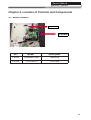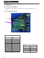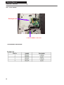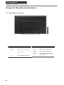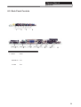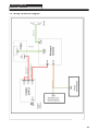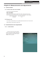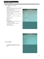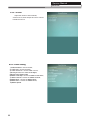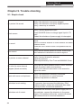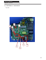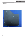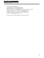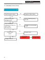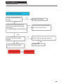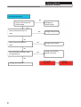
1
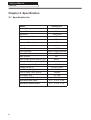
SERVICE MANUAL LED TV Model No. 48DR3505 MSD3393LU Chassis WARNING This service information is designed for experienced repair technicians only and is not designed for use by the general public. It does not contain warnings or cautions to advise non-technical individuals of potential dangers in attempting to service a product. Products powered by electricity should be serviced or repaired only by experienced professional technicians. Any attempt to service or repair the product or products dealt with in this service information by anyone else could result in serious injury or death. ©2014 Qingdao Haier Electronics Co., Ltd. All rights reserved. Unauthorized copying and distribution is a violation of law. Service Manual Model No.: 48DR3505 CONTENTS Chapter 1. General Information 1-1. Document Information ..............................................................3 1-2. General Guidelines.....................................................................3 1-3. Important Notice.........................................................................3 1-3-1. Follow the regulations and warnings ..................................................... 3 1-3-2. Be careful to the electrical shock ............................................................3 1-3-3. Electro static discharge (ESD)............................................................... .3 1-3-4. About lead free solder (PbF)...................................................................4 1-3-5. Use the genewing parts (specied parts) .............................................. 4 1-3-6 Safety check after repairment................................................................. 4 1-3-7. Ordering Spare Parts............................................................................. 6 1-3-8. Photo used in this manual .....................................................................6 1-4. How to Read this Service Manual ............................................6 Using icons ...............................................................................................................6 Chapter 2. Specication 2-1. Specication list.........................................................................8 2-2. External pictures (four faces)....................................................9 Chapter 3. Disassemble and Assemble 3-1. 48D3505 .................................................................................11 3-1-1. Remove the Stand.................................................................................11 3-1-2. Remove the Back Cabinet ....................................................................11 3-1-3. Remove the Mainboard.........................................................................11 3-1-4. Remove the Power Supply Module ......................................................11 3-1-5. Remove the Speaker.............................................................................11 3-1-6. Remove the Remote Control Board .....................................................12 3-1-7. Remove the Key Board.........................................................................12 Chapter 4. Location of Controls and Components 4-1. Board Location .........................................................................13 4-2. Mainboard .................................................................................14 4-2-1. Function Description .............................................................................14 4-2-2. Connector denition ..............................................................................14 4-3. Power Supply Module ..............................................................15 4-3-1. Function Description .............................................................................15 1 Service Manual Model No.: 48D3505 4-3-2. Connector denition ..............................................................................15 4-4. LCD Panel ..................................................................................16 Chapter 5. Installation Instructions 5-1. Accessories ..............................................................................18 5-2. External Equipment Connections............................................19 Chapter 6. Operation Instructions 6-1. Front Panel Controls.................................................................20 6-2. Back Panel Controls .................................................................21 6-3. Setting Up Your Remote Control .............................................22 Chapter 7. Electrical Parts 7-1. Block Diagram............................................................................23 7-2. Circuit Diagram..........................................................................30 Chapter 8. Measurements and Adjustments 8-1. Service Mode ............................................................................31 8-1-1.How to enter into Service Mode............................................................ 31 8-1-2.How to exit ............................................................................................31 8-2. Measurements and Adjustments ............................................31 8-2-1. The Main Menu ....................................................................................31 8-2-2. General Setting ....................................................................................32 8-2-3. Picture ..................................................................................................32 8-2-4. Sound................................................................................................... 33 8-2-5. Debug...................................................................................................33 8-3. Software Update ......................................................................34 8-3-1. 3393.72 software update ....................................................................34 Chapter 9. Trouble shooting 9-1. Simple check ...........................................................................35 9-2. Mainboard IC Introduction......................................................38 9-3. Mainboard Failure Check........................................................39 9-4. Pannel Failure..........................................................................45 2 Service Manual Model No.: 48DR3505 Chapter 1. General Information 1-1. Document Information Document format: Adobe PDF Author: Zhu Yapeng Compiler: 1-2. General Guidelines When servicing, observe the original lead dress. If a short circuit is found, replace all parts which have been overheated or damaged by the short circuit. After servicing, see to it that all the protective devices such as insulation barriers, insulation papers shields are properly installed. After servicing, make the following leakage current checks to prevent the customer from being exposed to shock hazards. 1) Leakage Current Cold Check 2) Leakage Current Hot Check 3) Prevention of Electro Static Discharge (ESD) to Electrostatically Sensitive 1-3. Important Notice 1-3-1. Follow the regulations and warnings Most important thing is to list up the potential hazard or risk for the service personnel to open the units and disassemble the units. For example, we need to describe properly how to avoid the possibility to get electrical shock from the live power supply or charged electrical parts (even the power is off). This symbol indicates that high voltage is present inside.It is dangerous to make any king of contact with any inside part of this product. This symbol indicates that there are important operating and maintenance instructions in the literture accompanying the appliance. 1-3-2. Be careful to the electrical shock To prevent damage which might result in electric shock or re, do not expose this TV set to rain or excessive moisture. This TV must not be exposed to dripping or splashing water, and objects lled with liquid, such as vases, must not be placed on top of or above the TV. 1-3-3. Electro static discharge (ESD) Some semiconductor (solid state) devices can be damaged easily by static electricity. Such 3 Service Manual Model No.: 48DR3505 components commonly are called Electrostatically Sensitive (ES) Devices. The following techniques should be used to help reduce the incidence of component damage caused by electros static discharge (ESD). Electrostatically Sensitive (ES) Devices Some semiconductor (solid-state) devices can be damaged easily by static electricity. Such components commonly are called Electrostatically Sensitive (ES) Devices. Examples of typical ES devices are integrated circuits and some field-effect transistors and semiconductor "chip" components. The following techniques should be used to help reduce the ncidence of component damage caused by static by static electricity. 1. Immediately before handling any semiconductor component or semiconductor-equipped assembly, drain off any electrostatic charge on your body by touching a known earth ground. Alternatively, obtain and wear a commercially available discharging wrist strap device, which should be removed to prevent potential shock reasons prior to applying power to the unit under test. 2. After removing an electrical assembly equipped with ES devices, place the assembly on a conductive surface such as aluminum foil, to prevent electrostatic charge buildup or exposure of the assembly. 1-3-4. About lead free solder (PbF) This product is manufactured using lead-free solder as a part of a movement within the consumer products industry at large to be environmentally responsible. Lead-free solder must be used in the servicing and repairing of this product. 1-3-5. Use the genewing parts (specied parts) Special parts which have purposes of re retardant (resistors), high-quality sound (capacitors), low noise (resistors), etc. are used. When replacing any of components, be sure to use only manufacture's specied parts shown in the parts list. Safety Component ● Components identied by mark have special characteristics important for safety. 1-3-6 Safety check after repairment Conrm that the screws, parts and wiring which were removed in order to service are put in the original positions, or whether there are the positions which are deteriorated around the serviced places serviced or not. Check the insulation between the antenna terminal or external metal and the AC cord plug blades. And be sure the safety of that. General Servicing Precautions 4 Service Manual Model No.: 48DR3505 1. Always unplug the receiver AC power cord from the AC power source before: a. Removing or reinstalling any component, circuit board module or any other receiver assembly. b. Disconnecting or reconnecting any receiver electrical plug or other electrical connection. c. Connecting a test substitute in parallel with an electrolytic capacitor in the receiver. CAUTION: A wrong part substitution or incorrect polarity installation of electrolytic capacitors may result in an explosion hazard. 2. Test high voltage only by measuring it with an appropriate high voltage meter or other voltage measuring device (DVM, FETVOM, etc) equipped with a suitable high voltage probe. Do not test high voltage by "drawing an arc". 3. Do not spray chemicals on or near this receiver or any of its assemblies. 4. Unless specified otherwise in this service manual, clean electrical contacts only by applying the following mixture to the contacts with a pipe cleaner, cotton-tipped stick or comparable nonabrasive applicator; 10% (by volume) Acetone and 90% (by volume) isopropyl alcohol (90%-99% strength). CAUTION: This is a ammable mixture. Unless specied otherwise in this service manual, lubrication of contacts is not required. Capacitors may result in an explosion hazard. 5. Do not defeat any plug/socket B+ voltage interlocks with which receivers covered by this service manual might be equipped. 6. Do not apply AC power to this instrument and/or any of its electrical assemblies unless all solid-state device heat sinks are correctly installed. 7. Always connect the test receiver ground lead to the receiver chassis ground before connecting the test receiver positive lead. Always remove the test receiver ground lead last. Capacitors may result in an explosion hazard. 8. Use with this receiver only the test xtures specied in this service manual. CAUTION: Do not connect the test xture ground strap to any heat sink in this receiver. 9. Remove the antenna terminal on TV and turn on the TV. 10. Insulation resistance between the cord plug terminals and the eternal exposure metal should be more than Mohm by using the 500V insulation resistance meter. 11. If the insulation resistance is less than M ohm, the inspection repair should be required. If you have not the 500V insulation resistance meter, use a Tester. External exposure metal: Antenna terminal Headphone jack. 5 Service Manual Model No.: 48DR3505 12. Use only a grounded-tip soldering iron to solder or unsolder ES devices. 13. Use only an anti-static type solder removal device. Some solder removal devices not classied as "anti-static" can generate electrical charges sufcient to damage ES devices. 14. Do not use freon-propelled chemicals. These can generate electrical charges sufficient to damage ES devices. 15. Do not remove a replacement ES device from its protective package until immediately before you are ready to install it. (Most replacement ES devices are packaged with leads electrically shorted together by conductive foam, aluminum foil or comparable conductive material). 16. Immediately before removing the protective material from the leads of a replacement ES device, touch the protective material to the chassis or circuit assembly into which the device will be installed. CAUTION: Be sure no power is applied to the chassis or circuit, and observe all other safety precautions. 17. Minimize bodily motions when handling unpackaged replacement ES devices. (Otherwise harmless motion such as the brushing together of your clothes fabric or the lifting of your foot from a carpeted oor can generate static electricity sufcient to damage an ES device.) 1-3-7. Ordering Spare Parts Please include the following informations when you order parts. (Particularly the Version letter) 1. Model number, serial number and software version The model number and serial number can be found on the back cover of each product. Software version can be found in the Spare Parts List. 2. Spare part No. and description Spare part No. and description can be found in the Spare Parts List. 1-3-8. Photo used in this manual The illustration and photos used in this Service Manual may not base on the final design of products, which may differ from your products in some way. 1-4. How to Read this Service Manual Using icons Icons are used to attract the attention of the reader to specic information. The meaning of each icon is described in the table below: Note: A “note” provides information that is not indispensable, but may nevertheless be valuable to the reader, such as tips and tricks. 6 Service Manual Model No.: 48DR3505 Caution: A “caution ” is used when there is danger that the reader, through incorrect manipulation, may damage equipment, loose data, get an unexpected result or has to restart(part of) a procedure. Warning: A “warning” is used when there is danger of personal injury. Reference: A “reference” guides the reader to other places in this binder or in this manual, where he/she will nd additional information on a specic topic. 7 Service Manual Model No.:48DR3505 Chapter 2. Specication 2-1. Specication list Model Screen Size 47.6" Aspect Ratio 16:9 Resolution Brightness (cd/m²) Contrast Response Time (ms) 1920x1080 250 1200:1 8 Angel of View H:160°, V:150° Color Display 16.7M OSD Language English,French,Spanish. Color System NTSC Audio System MN Audio Output Power (Built-in) (W) Audio Output Power (outer) (W) Total Power Input (W) Voltage Range (V) Power Frequency (Hz) 8 48DR3505 8W×2 No 140W AC100V~240V 50~60Hz Time of Sleep Timer (MINS) 240Min Net Weight (KG) 22.7 lbs Gross Weight (KG) 21.8 lbs Dimensions with Stand 42.7" x 26.2" x 9.8" Dimensions without Stand 42.7" x 24.8" x 3.0" Service Manual Model No.: 48DR3505 2-2. External pictures (four faces) Front Side Up Side 9 Service Manual Model No.: 48DR3505 Right Side Back Side 10 Service Manual Model No.: 48DR3505 Chapter 3. Disassemble and Assemble 3-1. 48DR3505 3-1-1. Remove the Stand 3-1-3. Remove the Mainboard 1. Remove the six screws indicated with red circles. 2. Remove the Mainbord. 1. Lay down the TV set . 2. Remove the four screws from the stand which in the picture above. 3. Remove the stand. 3-1-2. Remove the Back Cabinet 3-1-5. Remove the Speaker Remove the Speaker indicated by red circle in below picture. 1.Remove the screws indicated with red circles. 2. Flip machine, panel side up. 3.Carefully raise the Front shell from bottom. 11 Service Manual Model No.: 48DR3505 3-1-6. Remove the Remote Control Board And the Key Board Remove the Remote Control Board and the Key Board indicated by red circle in below picture. 12 Service Manual Model No.: 48DR3505 Chapter 4. Location of Controls and Components 4-1. Board Location B Panel A Board No. Model Description A Board TP.MS3393.PC821 Mainboard B Panel ST4761B01-5 LCD Panel 13 Service Manual Model No.: 48DR3505 4-2. Mainboard 4-2-1. Function Description Process signal which incept from exterior equipment then translate into signal that panel can display. 4-2-2. Connector denition CN18 CN6 IR & Key Interface CN6 Pin number 1 2 3 4 5 6 7 8 9 10 11 12 13 14 14 Signal name 5V RED GRE IR GND K0 K1 K2 K3 K4 K5 K6 K7 GND Speaker connector CN18 Pin number Signal name 1 ROUT+ 2 ROUT- 3 LOUT- 4 LOUT+ Service Manual Model No.: 48DR3505 4-4. LCD Panel Backlight Unit LVDS CONNECTOR CN1 Connector Denition 16 Service Manual Model No.: 48DR3505 17 Service Manual Model No.: 48DR3505 Chapter 5. Installation Instructions 5-1. Accessories Batteries Remote Control 18 Service Manual Model No.: 48DR3505 5-2. External Equipment Connections Antenna Connection Connect your aerial to the back of the TV into the ANTENNA IN socket. Improve Your Signal To improve picture quality in a poor signal area, use a signal amplier (not supplied). Connect Your PC to the TV You can use your TV as a monitor for your personal computer by connecting it with a VGA cable (not supplied). A Read your computer user guide and check it has a VGA connector. B Turn off your TV and PC. C Connect a D type 15-pin VGA interface cable to the VGA video interface connector on the PC. Connect the other end of the cable to the PC interface connector on the TV. Tighten the screws on the VGA connectors and connect the audio cable (not supplied) to the audio input socket on the back of the TV. D E Turn on the TV rstly and then the PC. F Once the image shows, if there is noise present, change the PC mode to other resolutions, change the refresh rate to other rate or adjust the brightness and contrast on the menu until the picture is clear. Connect a DVD Player or VCR to Your TV There are two ways in which you can connect a DVD player or VCR to your TV. Make sure that both the TV and DVD player or VCR are switched off before you connect them. HDMI Input A B C Connect the cable from the HDMI device to the TV HDMI socket. Press the SOURCE button to select HDMI mode. Refer to the HDMI device user guide for how to operate. Press the Source button on the TV or TV remote control to set the video input mode to PC. Connect a DVD Player to Your TV Connect the DVD video outputs (Y, Pb, Pr) to the COMPONENT (Y, Pb, Pr) IN socket on your TV. A B Turn on the DVD player and insert a DVD disk. C Refer to the DVD player user guide for operating Press the SOURCE button to select COMPONENT mode. instructions. 19 Service Manual Model No.: 48DR3505 Chapter 6. Operation Instructions 6-1. Front Panel Controls 20 1 POWER Press to turn the TV on and off. 2 CH- TV channel down. 3 CH+ TV channel up. 4 VOL- Press to decrease the volume. 5 VOL+ Press to increase the volume. 6 MENU Press to select the main menu. 7 INPUT Toggles between all the vailable input sources. Service Manual Model No.: 48DR3505 6-2. Back Panel Controls 1 2 5 1 2 Optical AV YPbPr 3 4 HDMI3 5 HDMI2(MHL) 6 HDMI2 7 VGA 8 PC Audio 9 RF 10 Line out 11 USB 3 6 4 7 8 9 10 11 output input intput input input input input input input output input 21 Service Manual Model No.: 48DR3505 6-3. Setting Up Your Remote Control When using the remote control, aim it towards the remote sensor on the TV. 1 2 3 4 5 21 6 7 8 9 10 11 12 14 13 16 15 18 17 19 20 21 22 23 24 25 26 22 1 2 3 4 5 6 7 8 9 10 11 12 13 14 15 16 17 18 19 20 21 22 23 24 25 26 POWER. INPUT. USB Shortcut button. CC. HOME; Program Number Channel selection. RECALL button. VOL+/VOL-: Volume selection. CH∧/CH∨: Channel selection. Mute. Menu button. Back button. Exit button. DISPLAY button. SAP button. Sleep button. Wide button. Audio button. Picture Mode. OK button. Channel List. Favorite program. Play / Pause button (only for USB). EPG button. Fast Reverse (only for USB). Fast Forward (only for USB). Service Manual Model No.: 48DR3505 Chapter 7. Electrical Parts 7-1. Circuit Diagram 5V_M 33ohm-0402-±5%-1/16W MMBT3904(f≥350MHz) PIRB402 NC/2K2ohm-0402-±5%-1/16W 10Kohm-0402-±5%-1/16W CORB4 RB4 1Kohm-0402-±5%-1/16W COCN4 CN4 12V GND 5V_M 5V_M 5V_Panel 5V_Panel GND GND NLPW0ON PW_ON 5V_STB NL5V0M 5V_M PIE101 PIE201 PIC102 COC56 C56 NL5V0STB 5V_STB PIRB102 COE2 PIC5702 E2 PIC5802 COC1 C1 5V_M COC58 C58 PIE102 CORB1 RB1 PIC202 + COE1 E1 PIC5602 + 1 2 GND PICN402 3 5V PICN403 4 5V PICN404 5 P5V PICN405 6 P5V PICN406 GND 7 PICN407 8 GND PICN408 9 PWON PICN409 10 5VSB PICN4010 12VPICN401 COC57 C57 PIE202 PIC5601 PIC101 PIRB101 PIC5801 PIC5701 PIC201 CORB2 RB2 PIRB202 NC/100uF-16V 10uF-0805 0.1uF-0402 NC/10uF-0805 GND 10PIN-2.54-D-H-G NC/100uF-16V 10uF-0805 0.1uF-0402 GND NLBL0EN BL_EN PIRB201 PIQB10C CORB5 RB5 PIRB502 PIRB501 COUL1 UL1 3 PICL102 COCL1 CL1 PIUL102 VO PIUL104 PIRB1 02 PIQB30E PIQB10B PIQB10E GND COCN2 CN2 PICL202 4 COCL2 CL2 1 1 GND NLGND 2 GND NLADJ 3 ADJ BLON 4 BL_ON PICN204 NL12V 5 12V 12V PICN205 6 12V 12V PICN206 GND PICN201 PICL302 GND PICN202 COCL3 CL3 PICL201 ADJ PICL301 CORB6 RB6 SMD5845-4R7M-032 22uF-0805-X5R-±20%-6.3V 0.1uF-0402-Y5V-+80%-20%-16V 5V_STB COLD1 LD1 COUD1 UD1 4 PIUD104 PICD101 PICD201 SW 3 PIUD103 PILD101 PILD102 1.15V_STB CO1015V0STB 1.15V_STB TEST CORD1 RD1 COCD2 CD2 PPIUD101 IRD102 1 PICD202 LC3406CB5TR EN PIRD202 CORD3 RD3 PIUD102 GND GND COCD3PICD302 COCD4 CD3 CD4 PICD402 COCD5 CD5 PICD502 PICD301 PICD401 PIRB602 PIRB702 PIRB901 PIRB802 PICB102 PIQB20B PICB101 3 PIUL203 PICL502 0ohm-1206-±5%-1/4W PICL402 PVCC CL5 COCL5 QM2 COQM2 RM5 CORM5 CN3 COCN3 GND PIRM201 0.1uF-0402-Y5V-+80%-20%-16V 10uF-0805-X5R-±20%-16V NC/3K3ohm-0402-±5%-1/16W NL5V0Panel 1 5V_Panel PICN301 NLPVCC 2 PVCC PVCC PICN302 12V 12V3 PICN303 PIRM502 GND VO PIUL204 4 PIUL201 PICM201 PIRL102 PICL6 CCOCL6 L602 PICL702 PIRL101 PIRL202 PICL601 PICL701 1 CORL1 RL1 0.1uF-0402-Y5V-+80%-20%-16V 10uF-0603-X5R-±20%-6.3V 330ohm-0402-±1%-1/16W 150ohm-0402-±1%-1/16W 0.1uF-0402-Y5V-+80%-20%-16V 10uF-0603-X5R-±20%-6.3V CORL2 RL2 GND PIRL201 GND PIRM302 5V PIQM20E CORM2 RM2 CM6 PICM601 RM3 CORM3 PIRM501 CM2PICM202 PICM602 COCM2 COCM6 WPM3407C-3/TR PIRM301 3K3ohm-0402-±1%-1/16W 2K2ohm-0402-±5%-1/16W 0ohm-0402-±5%-1/16W MMBT3904(f≥350MHz) 200Kohm-0402-±5%-1/16W GND PIRM202 PIQM10G PIQM20C PIUL202 LC1117CLTRAD PIQM10D CORM1 RM1 PIRM402 PIQM20B 2 VO VCC_Panel COQM1 QM1 CORM4 RM4 1V8_DDR VI ADJ PIRL302 PICL401 PIRM102 GND COUL2 UL2 CORL3 RL3 PIRL301 PICL501 PIRM401 PICB201 PICD501 12K4ohm-0402-±1%-1/16W 13Kohm-0402-±1%-1/16W 10uF-0603-X5R-±20%-6.3V PIQM10S CORB8 RB8 COCB2 CB2 GND COCL4 CL4 NLPOW0EN POW_EN PICB202 CB1 COCB1 5V_M PIRM101 ADJ PIRB701 COQB2 QB2 510ohm-0402-±5%-1/16W PIQB20E MMBT3904(f≥350MHz) 10Kohm-0402-±5%-1/16W GND 1Kohm-0402-±5%-1/16W 1uF-0402-X5R-±20%-6.3V NC/3K3ohm-0402-±5%-1/16W 0.1uF-0402-Y5V-+80%-20%-16V PIRD302 PIRD301 CORB7 RB7 PIRB601 PIQB20C RB9 CORB9 NLPWM0ADJ PWM/ADJPIRB902 -G PIRB801 PI105VSTB01 RD2 CORD2 5 PIUD105 PIRD201 2 10Kohm-0402-±5%-1/16W 10uF-0603-X5R-±20%-6.3V GND 0.1uF-0402-Y5V-+80%-20%-16V FB GND COCD1 CD1 VIN PICN203 6PIN-2.0-D-H- 5V_M PICD102 GND GND LC1117CLTR33 0.1uF-0402-Y5V-+80%-20%-16V 10uF-0603-X5R-±20%-6.3V 0.1uF-0402-Y5V-+80%-20%-16V GND PIRD101 CORB11 RB11 PIRB301 PIQB30B COQB1 QB1 2 VO PIUL10 PICL101 PIRB302 PIRB1 01 3V3_STB VI ADJ PIUL103 NLBL0ON BL_ON COQB3 QB3 CORB3 RB3 10Kohm-0402-±5%-1/16W NC/0ohm-0402-±5%-1/16W 1Kohm-0402-±5%-1/16W MMBT3904(f≥350MHz) 5V_STB PIRB401 RB10 CORB10 PIRB1001 PIQPIRB1002 B30C COC2 C2 GND COH1 H1 COH2 H2 COH3 H3 COH4 H4 COH5 H5 COH6 H6 PIH10654321 PIH20654321 PIH30654321 PIH40654321 PIH50654321 PIH60654321 LocationLocation hole Location hole Location hole Location hole Location hole hole GND CL7 COCL7 GND COU1 U1 RX0P_B RX0N_B RXCP_B RXCN_B RX2P_D RX2N_D RX1P_D RX1N_D RX0P_D RX0N_D RXCP_D RXCN_D VDDC/AVDDL_DVI GND_EFUSE AVDD_5V HOTPLUG_B DDCDB_CL DDCDB_DA MHL_DET DDCDA_DA DDCDA_CL DDCDC_DA DDCDC_CL VDDIO_DATA VDDC/DVDD_DDR_DATA SAR2 RX1N_B RX1P_B NLHDMI20RX20N 3 HDMI2_RX2_NPIU103 RX2N_B NLHDMI20RX20P 4 HDMI2_RX2_P 5 NLHDMI30RXC0N 6 HDMI3_RXC_N PIU106 NLHDMI30RXC0P 7 HDMI3_RXC_P PIU107 NLHDMI30RX00N 8 HDMI3_RX0_NPIU108 NLHDMI30RX00P 9 HDMI3_RX0_PPIU109 NLHDMI30RX10N 10 HDMI3_RX1_NPIU1010 NLHDMI30RX10P 11 HDMI3_RX1_PPIU1011 NLHDMI30RX20N 12 HDMI3_RX2_NPIU1012 NLHDMI30RX20P 13 HDMI3_RX2_PPIU1013 NLVGA0HS 14 VGA_HS PIU1014 NLVGA0BIN 15 VGA_BIN PIU1015 NLVGA0GIN 16 VGA_GIN PIU1016 NLGIN0M 17 GIN0M PIU1017 NLVGA0RIN 18 VGA_RIN PIU1018 NLVGA0VS 19 VGA_VS PIU1019 20 PIU1020 3V3_STB NLHD10Pb 21 HD1_Pb PIU1021 NLHD10SOG 22 HD1_SOG PIU1022 23 NLHD10Y HD1_Y PIU1023 24 NLGIN1M GIN1M PIU1024 NLHD10Pr 25 HD1_Pr PIU1025 26 PIU1026 27 PIU1027 NLAV0IN 28 AV_IN PIU1028 NLVCOM 29 VCOM PIU1029 CVBS1_OUT COCVBS10OUT NLCVBS10OUT 30 CVBS1_OUT PIU1030 TEST PICVBS10OUT01 31 PIU1031 1.15V_STB 32 PIU1032 +3_3V_AU NLPC0RIN 33 PC_RIN PIU1033 34 NLPC0LIN PC_LIN PIU1034 35 NLDVD0RIN DVD_RIN PIU1035 NLDVD0LIN 36 DVD_LIN PIU1036 NLAU0VAG 37 AU_VAG PIU1037 PIC302 PIC401 NLAU0VRM 38 AU_VRM PIU1038 COC3 COC4 C3 C4 3V3_STB PIC402 PIFB101 COFB1 FB1 GND PICD902 COCD8 CD8 PICD801 PICD10 2 COCD9 CD9 PICD901 102 101 100 PIU10100 99 PIU1099 98 PIU1098 97 PIU1097 96 PIU1096 95 PIU1095 94 PIU1094 93 PIU1093 92 PIU1092 91 PIU1091 90 PIU1090 89 PIU1089 88 PIU1088 87 PIU1087 86 PIU1086 85 PIU1085 84 PIU1084 83 PIU1083 82 PIU1082 81 PIU1081 80 PIU1080 79 PIU1079 78 PIU1078 77 PIU1077 76 PIU1076 75 PIU1075 74 PIU1074 73 PIU1073 72 PIU1072 71 PIU1071 70 PIU1070 69 PIU1069 68 PIU1068 67 PIU1067 66 PIU1066 65 PIU1065 PIU10102 PIU10101 NLAV0LIN LAV0RIN PICL802 PICL902 COCL16 CL8 COCL8 CL16 PICL1601 PICL801 COCL9 CL9 PICL901 GND 1uF-0402-X5R-±20%-6.3V 0.1uF-0402-Y5V-+80%-20%-16V 0.1uF-0402-Y5V-+80%-20%-16V NLLED0RED LED_RED NLKEY KEY COFB2 +3_3V_AU FB2 3V3_STB 3V3_STB NLUSB10DP USB1_DP NLUSB10DM USB1_DM PIFB201 PIFB301 PICL1702 NLUSB00DP USB0_DP NLUSB00DM USB0_DM NLRESET0H RESET_H NLDVD0EN' DVD_EN' COFB3 +3_3V_PLL FB3 3V3_STB PIFB202 PIFB302 PICL1802 COCL17 CL17 PICL1701 COCL18 CL18 PICL1801 NLREMOTE REMOTE NLHDMI0CEC HDMI-CEC GND FCM1005KF-121T06(120ohm-500mA) 0.1uF-0402-Y5V-+80%-20%-16V GND NLUART0RX0DDC UART-RX/DDC NLUART0TX0DDC UART-TX/DDC NLHDMI0ARC HDMI-ARC SPI_SCK SPI_CSN SPI_SDI SPI_SDO PWM/ADJ BL_EN NLHOTPLUG3' HOTPLUG3' NLHOTPLUG1' HOTPLUG1' NLRXO00N RXO0_N NLRXO00P RXO0_P NLRXO10N RXO1_N NLRXO10P RXO1_P NLRXO20N RXO2_N NLRXO20P RXO2_P GND FCM1005KF-121T06(120ohm-500mA) 0.1uF-0402-Y5V-+80%-20%-16V FCM1005KF-121T06(120ohm-500mA) +3_3V_ADC COFB4 FB4 3V3_STB PIFB401 PICL1902 PICL10 2 PICL1202 PICL10 1 PICL1201 COCL19 CL19 COCL10 CL10 PIFB402 PICL1302 PICL1402 PICL20 2 PICL1301 PICL1401 PICL20 1 COCL12 CL13 COCL13 CL14 COCL14 CL12 PICL1502 COCL20 CL20 COCL15 CL15 PIC1402 COC14 C14 PICL1901 PICL1501 PIC1401 GND GND 3V3_STB NLRXO30N RXO3_N NLRXO30P RXO3_P NLRXE00N RXE0_N 1uF-0402-X5R-±20%-6.3V 0.1uF-0402-Y5V-+80%-20%-16V 0.1uF-0402-Y5V-+80%-20%-16V 0.1uF-0402-Y5V-+80%-20%-16V 0.1uF-0402-Y5V-+80%-20%-16V 0.1uF-0402-Y5V-+80%-20%-16V 1uF-0402-X5R-±20%-6.3V 0.1uF-0402-Y5V-+80%-20%-16V COR3 R3 NLAMP0LO' AMP-LO' PIR302 NLRXE00P RXE0_P NLAMP0LO AMP-LO PIR301 0ohm-0402-±5%-1/16W COR4 R4 NLRXE10N RXE1_N NLRXE10P RXE1_P NLRXE20N RXE2_N NLAMP0RO' AMP-RO' PIR402 NLAMP0RO AMP-RO PIR401 0ohm-0402-±5%-1/16W NLRXE20P RXE2_P PIR502 COR5 R5 PIR501 PIU1039 PIU104 PIU104 PIU1042 PIU1043 PIU104 PIU1045 PIU1046 PIU1047 PIU1048 PIU1049 PIU105 PIU105 PIU1052 PIU1053 PIU1054 PIU105 PIU1056 PIU1057 PIU1058 PIU1059 PIU106 PIU106 PIU1062 PIU1063 PIU1064 0.1uF-0402-Y5V-+80%-20%-16V FCM1005KF-121T06(120ohm-500mA) 10uF-0603-X5R-±20%-6.3V PICL1602 COCD10 CD10 PICD10 1 39 40 41 42 43 44 45 46 47 48 49 50 51 52 53 54 55 56 57 58 59 60 61 62 63 64 PIFB102 PICD802 GND 0.1uF-0402-Y5V-+80%-20%-16V 0.1uF-0402-Y5V-+80%-20%-16V 0.1uF-0402-Y5V-+80%-20%-16V 0.1uF-0402-Y5V-+80%-20%-16V PIR602 COR6 R6 PIR601 PIC501 COC5 C5 PIC502 PIC601 COC6 C6 PIC602 200Kohm-0402-±5%-1/16W 200Kohm-0402-±5%-1/16W 1000pF-0402-X7R-±10%-50V 1000pF-0402-X7R-±10%-50V GND AV_LIN AV_RIN AMP-LO' AMP-RO' LINE_L_OUT LINE_R_OUT IF_AGC VIFP VIFM +3_3V_ADC +3_3V_PLL XTALI XTALO 3V3_STB 1V8_DDR 1.15V_STB M_SDA M_SCL HDMI3_DET AMP-MUTE POW_EN SPDIF_OUT RXE3_P RXE3_N RXEC_P RXEC_N PIC301 PIU105 RX2P_B AVDD_MOD RXCN_A RXCP_A RX0N_A RX0P_A RX1N_A RX1P_A RX2N_A RX2P_A HSYNC0 BIN0P GIN0P GIN0M RIN0P VSYNC0 AVDD3P3_ADC BIN1P SOGIN1 GIN1P GIN1M RIN1P VSYNC1 CVBS1 CVBS0 VCOM CVBS_OUT1 VDDC AVDD_AU33 AUR0 AUL0 AUR1 AUL1 VAG VRM AUL4 AUR4 AUOUTL3 AUOUTR3 AUOUTL0 AUOUTR0 IFAGC VIFP VIFM AVDD3P3_DADC AVDD3P3_DMPLL XIN XOUT AVDD_MOD VDDIO_CMD VDDC/DVDD_DDR_CMD GPIO0/GPIO44 GPIO1/GPIO45 GPIO2/GPIO46 GPIO3/GPIO47 GPIO4/GPIO48 GPIO5/GPIO49 LVA3P LVA3M LVACKP LVACKM PIU104 SAR1 SAR0 AVDD_MOD DP_P1 DM_P1 DP_P0 DM_P0 RESET INT/GPIO64 IRIN CEC TEST DDCA_CK DDCA_DA ARC SPI_CK SPI_CZ SPI_DI SPI_DO PWM0 PWM1 HOTPLUG_A HOTPLUG_C/D LDE/LVB0M LCK/LVB0P LVB1M LVB1P LVB2M LVB2P AVDD_MOD LVB3M LVB3P LVA0M LVA0P LVA1M LVA1P LVA2M LVA2P 1V8_DDR COCD7 CD7 PICD701 PIU1028 PIU1027 PIU1026 PIU1025 PIU1024 PIU1023 PIU102 PIU102 PIU102 PIU10 9 PIU10 8 PIU10 7 PIU10 6 PIU10 5 PIU10 4 PIU10 3 PIU10 2 PIU10 PIU10 PIU10 9 PIU10 8 PIU10 7 PIU10 6 PIU10 5 PIU10 4 PIU10 3 129 1 PIU101 NLHDMI20RX10P 2 HDMI2_RX1_PPIU102 PICD702 128 127 126 125 124 123 122 121 120 119 118 117 116 115 114 113 112 111 110 109 108 107 106 105 104 103 PIU1029 E-PAD NLHDMI20RX10N HDMI2_RX1_N AVDD5V_MHL HOTPLUG2' HDMI2_SCL HDMI2_SDA MHL_CABLE-DET HDMI3_SDA HDMI3_SCL HDMI1_SDA HDMI1_SCL 1V8_DDR 1.15V_STB ARC_DET HDMI2_RX0_P HDMI2_RX0_N HDMI2_RXC_P HDMI2_RXC_N HDMI1_RX2_P HDMI1_RX2_N HDMI1_RX1_P HDMI1_RX1_N HDMI1_RX0_P HDMI1_RX0_N HDMI1_RXC_P HDMI1_RXC_N 1.15V_STB NLHDMI20RXPNLHDMI20RXNLHDMI20RXCPNLHDMI20RXCNLHDMI10RX2NLPHDMI10RX2NLHDMI10RXPNLHDMI10RXNLHDMI10RXPNLHDMI10RXNLHDMI10RXCPNLHDMI10RXCN NLAVD50MHLN OTPLUG2'NLHDMI20SCLNHDMI20SDANLMH0CABEDNLTHDMI30SDANLHMI30SCLNHDMI10SDANLHMI10SCLN1V80DRNL105VSTBNLARC0DET GND MSD3393LU 1.15V_STB 3V3_STB NLIE0LOUNTIE0ROUTNLIF0AGC NLVIFMNL03 VADCNL03 VPLNLXTALNILXTALONL3V0STB NLM0SDANLM0SCLNLHDMI30DENTLAMP0UTENLPOW0ENNLSPDIF0OUTNLRXE30PNLRXE30NLRXEC0PNLRXEC0N 3V3_STB UF1 COUF1 PIRF1201 NLVIFP CORF12 RF12 1 SPI_CSN NLSPI0CSN PIUF101 NLSPI0SDO 2 SPI_SDO PIUF102 PIRF1202 PICF1601 3 #F_WP NL#F0WPPIUF103 CF16 COCF16 NLGND GND 4 PIUF104 CE# 8 VDD PIUF108 HOLD# PIUF107 WP# SCK PIUF106 VSS SI PIUF105 SO 7 6 SPI_SCK NLSPI0SCK 5 NLSPI0SDI SPI_SDI PICF701 CF7 COCF7 PICF702 PICF1602 3V3_STB CF1 COCF1 XTALI PIR9 02 Y1 PIY102 COY1 PICF101 PIQF10C PICF102 GND R99 COR99 PICF1701 RF3 CORF3 QF1 COQF1 PIQF10E PIRF302 CF17 COCF17 PIRF402 PIRF301 RESET_H RF4 CORF4 PIR9 01 PIY101 PICF1702 CF2 COCF2 PICF201 33pF-0402-NPO-±5%-50V 33pF-0402-NPO-±5%-50V 1Mohm-0402-±5%-1/16W 24MHz-±20PPM-20PF-HC-49S-SMD PICF202 PIRF401 GND GND NLPWM0ADJ PWM/ADJ BL_EN NLBL0EN PIQF10B XTALO GND NC/0.1uF-0402-Y5V-+80%-20%-16V SGM810-SXN3L 100Kohm-0402-±5%-1/16W 1Kohm-0402-±5%-1/16W R1 COR1 PIR102 PIR101 R2 COR2 PIR202 PIR201 4K7ohm-0402-±5%-1/16W 4K7ohm-0402-±5%-1/16W GND GD25Q16BSIG 10Kohm-0402-±5%-1/16W NC/0.1uF-0402-Y5V-+80%-20%-16V 0.1uF-0402-Y5V-+80%-20%-16V GND 5V K7/N K6/P K5/M K4/V- K3/V+ K2/C- K1/C+ K0/S GND IR GRN RED 14 PICN6014 13 PICN6013 12 PICN6012 11 PICN6011 10 PICN6010 9 PICN609 8 PICN608 7 PICN607 6 PICN606 5 PICN605 4 PICN604 3 2 1 PICN603 PICN602 GND PICN601 PIRK1902 PIRK2002 PIQK20B LED_R LED_G IR GND NLK0 K0 NLK1 K1 NLK2 K2 NLK3 K3 NLK4 K4 NLK5 K5 NLK6 K6 NLK7 K7 PIRK2001 PIQK20C COCK1 CK1 PICK102 NLLED0R LED_R PIRK601 PIRK701 PIRK801 PICK302 PIDK10K PIDK10A DK1 CODK1 PICK301 3V3_STB NLKEY KEY CK2 COCK2 NLIR IR PICK602 PICK601 GND COCK6 CK6 0.1uF-0402-Y5V-+80%-20%-16V 22ohm-0402-±5%-1/16W 1Kohm-0402-±5%-1/16W 0.1uF-0402-Y5V-+80%-20%-16V 4K7ohm-0402-±1%-1/16W 1Kohm-0402-±5%-1/16W PIRK401 PIRK1101 PICK202 PICK201 CORK4 RK4 0.01uF-0402-X7R-±10%-50V PIRK402 CORK11 RK11 PIRK1102 NC/AVLC18S02003 4K7ohm-0402-±5%-1/16W 10Kohm-0402-±5%-1/16W 1Kohm-0402-±5%-1/16W MMBT3904(f≥350MHz) 0.67V 1.05V 1.36V 1.79V 2.24V 2.67V 0.32V NL5V0STB 5V_STB NLLED0RED LED_RED COCK3 CK3 PICK101 PIRK102 PIRK201 CORK1 RK1 CORK2 RK2 PIRK101 PIRK202 PIRK901 PIRK301 CORK3 RK3 PIRK302 CORK5 RK5 PIRK502 CORK6 RK6 PIRK602 CORK7 RK7 PIRK702 CORK8 RK8 PIRK802 CORK9 RK9 PIRK902 PIRK1001 PIRK501 CORK10 RK10 PIRK1002 LED_G NLLED0G QK2 COQK2 1K2ohm-0402-±5%-1/16W 2K2ohm-0402-±5%-1/16W 3K3ohm-0402-±1%-1/16W 5K6ohm-0402-±1%-1/16W 10Kohm-0402-±1%-1/16W 20Kohm-0402-±1%-1/16W 0ohm-0402-±5%-1/16W 5V_M CORK20 RK20 14PIN-2.0-D-H-G COCN6 CN6 PIRK2301 PIRK1901 PIRK2302 CORK19 RK19 RK23 CORK23 3V3_STB LED_RED PIQK20E GND PIRK1601 CORK16 RK16 CORK15 RK15 5V_STB PIRK1501 PIRK1502 PIRK1602 NLREMOTE REMOTE 10pF-0402-NPO-±5%-50V 4K7ohm-0402-±5%-1/16W 1Kohm-0402-±5%-1/16W RF7 CORF7 2 PICN502 4 PICN504 6 PICN506 8 PICN508 10 PICN5010 12 PICN5012 14 PICN5014 16 PICN5016 18 PICN5018 20 PICN5020 22 PICN5022 24 PICN5024 26 PICN5026 28 PICN5028 30 PICN5030 32 34 36 PICN5032 PICN5034 PICN5036 COCN5 CN5 1 VCC_Panel PICN501 3 VCC_Panel PICN503 5 GND PICN505 NLRXO00N 7 RXO0_N PICN507 NLRXO10N PICN509 9 RXO1_N NLRXO20N 11 RXO2_N PICN5011 13 GND PICN5013 15 RXEC_N PICN5015 NLRXO30N PICN5017 17 RXO3_N NLRXE00N 19 RXE0_N PICN5019 NLRXE10N PICN5021 5V_M 21 RXE1_N NLRXE20N 23 RXE2_N PICN5023 25 GND PICN5025 PIRF501 NLRXEC0N 27 RXEC_N PICN5027 RF5 CORF5 RXE3_N 29 NLRXE30N PICN5029 31 GND PICN5031 33 CON1/ NLCON10 PICN5033 35 M_SCL/ NLM0SCL0 PICN5035 PIRF502 PIRF701 PIRF702 GND PIRF6502 CORF65 RF65 PIRF6501 GND PIRF802 NLVCC0Panel VCC_Panel GND GND NLRXO00P RXO0_P NLRXO10P RXO1_P NLRXO20P RXO2_P GND RXEC_P NLRXO30P RXO3_P NLRXE00P RXE0_P NLRXE10P 5V_M RXE1_P NLRXE20P RXE2_P GND PIRF601 NLRXEC0P RXEC_P RF6 CORF6 NLRXE30P RXE3_P GND NLGND CON2/ NLCON20 PIRF602 PIRF801 M_SDA/ NLM0SDA0 RF8 CORF8 CON2/ NC/1Kohm-0402-±5%-1/16W NC/2Kohm-0402-±5%-1/16W NC/1Kohm-0402-±5%-1/16W NC/2Kohm-0402-±5%-1/16W NC/0ohm-0402-±5%-1/16W ADJ1 NLADJ1 COAV1 AV1 161031041( AV2 COAV2 SPCC) GND PIAV1023 PIAV102 PIAV102 PIAV102 GND SPCC) GND GND 1 RX2+PIAV101 2 GND PIAV102 3 RX2-PIAV103 4 RX1+PIAV104 5 GND PIAV105 7 6 RX1-PIAV106 RX0+PIAV107 PIAV109 9 8 GND PIAV108 RX0- PIAV1011 11 10 RXC+PIAV1010 GND 12 RXC-PIAV1012 13 CEC PIAV1013 15 14 ARC PIAV1014 SCL PIAV1015 16 SDA PIAV1016 17 GND PIAV1017 18 +5V PIAV1018 GND HPD +5V GND GND GND GND CEC HDMI1_SCL/ HDMI1_SDA/ GND HDMI1_5V HOTPLUG1 COCH10 CH10 CEC PICH10 2 PICH10 1 GND GND GND CEC PICH1802 NLHDMI10RX20P HDMI1_RX2_P NLHDMI10RX20N HDMI1_RX2_N NLHDMI10RX10P HDMI1_RX1_P NLHDMI10RX10N HDMI1_RX1_N NLHDMI10RX00P HDMI1_RX0_P NLHDMI10RX00N HDMI1_RX0_N NLHDMI10RXC0P HDMI1_RXC_P NLHDMI10RXC0N HDMI1_RXC_N HDMI1_SCL HDMI1_SDA GND CORH1 RH1 COCN1 CN1 1 2 PICN101 PICN102 3 4 PICN103 PICN104 5 6 PICN105 PICN106 7 8 PICN107 PICN108 9 10 PICN109 PICN1010 11 12 PICN1011 PICN1012 13 14 PICN1013 PICN1014 15 16 PICN1016 PICN1015 19 PICN1020 20 17 18 PICN1017 PICN1018 PICN1019 PIRH502 PICH202 PIRH401 PICH201 PIRH501 COCH2 CH2 CORH5 RH5 PIRH402 CORH4 RH4 PIRH2202 NLM0SDA M_SDA HDMI3_RX2_N HDMI3_RX1_N HDMI3_RX0_N HDMI3_RXC_N HDMI3_SDA GND HOTPLUG3 GND NL5V0M 5V_M CORH22 RH22 PIRH2201 NLHDMI10SCL0 HDMI1_SCL/ NLHDMI10SDA0 HDMI1_SDA/ NC/2*10PIN-2.0-D-H-M NC/100ohm-0402-±5%-1/16W NC/100ohm-0402-±5%-1/16W NLHDMI10SCL HDMI1_SCL HDMI1_5V NLHOTPLUG1' HOTPLUG1' PICH401 GND HOTPLUG2' NLHOTPLUG2' COAV3 AV3 NLHDMI105V HDMI1_5V HDMI2_5V NLHDMI205V SPCC) RH65 CORH65 PIRH6502 PIRH6501 PIQH50B PIAV3023 PIAV302 PIAV3021 PIAV302 PIRH1 02 PIRH1 01 GND PIQH50C PIRH6602 PIRH6901 PIRH6902 PIRH6701 PIRH6702 PIAV3019 1 RX2+ PIAV301 2 GND PIAV302 3 RX2- PIAV303 4 RX1+ PIAV304 5 GND PIAV305 6 RX1- PIAV306 7 RX0+ PIAV307 8 GND PIAV308 9 RX0PIAV309 10 RXC+ PIAV3010 11 GND PIAV3011 12 RXC- PIAV3012 13 CEC PIAV3013 14 ARC PIAV3014 15 SCL PIAV3015 16 SDA PIAV3016 17 GND PIAV3017 18 +5V PIAV3018 19 HPD PIRH70 1 3V3_STB GND GND GND GND PIRH7202 CORH6 RH6 PIRH602 PICH1202 COCH12 CH12 RH7 CORH7 PIRH702 PIRH601 PICH1201 PIRH701 RH56 CORH56 PIRH5602 NLHDMI30RX20P HDMI3_RX2_P NLHDMI30RX20N HDMI3_RX2_N NLHDMI30RX10P HDMI3_RX1_P NLHDMI30RX10N HDMI3_RX1_N NLHDMI30RX00P HDMI3_RX0_P NLHDMI30RX00N HDMI3_RX0_N NLHDMI30RXC0P HDMI3_RXC_P NLHDMI30RXC0N HDMI3_RXC_N HDMI3_SCL HDMI3_SDA GND NLGND RH55 CORH55 5V_STB HDMI3_DET NLHDMI30DET PIRH6001 COCH8 CH8 PIRH4301 PIQH20C COQH2 QH2 RH42 CORH42 PIRH4101 PIRH4102 CORH41 RH41 NLHOTPLUG3' HOTPLUG3' CORH44 RH44 CORH45 RH45 PIRH4402 PIRH4502 4 PIRH4401 PIRH4501 NLHDMI30SCL0 HDMI3_SCL/ NLHDMI30SDA0 HDMI3_SDA/ PICH101 PICH301 GND PICH601 GND PIRH50 2 PIRH50 1 CH6 COCH6PICH602 RH50 CORH50 RH18 CORH18 GND PIRH1802 HDMI2_5V NC/22pF-0402-NPO-±5%-50V NC/22pF-0402-NPO-±5%-50V GND PICH302 COCH3 CH3 PICH102 10Kohm-0402-±5%-1/16W 10Kohm-0402-±5%-1/16W COCH1 CH1 NLHDMI30SCL HDMI3_SCL NLHDMI30SDA HDMI3_SDA 6 PIUH106 OUT IN UH1 COUH1 PIUH105 1 PIUH101 GND ILIM PIUH104 FLAG NLFLAG 5 FLAG 2 PIUH102 EN 3 PIRH1902 MP65151DJ-LF-Z PIUH103 RH19 CORH19 PIRH1901 AVDD5V_MHL PIRH802 PIRH2902 PIRH1801 10Kohm-0402-±5%-1/16W 10uF-0603-X5R-±20%-6.3V 20Kohm-0402-±1%-1/16W NC/10Kohm-0402-±5%-1/16W 10Kohm-0402-±5%-1/16W 10Kohm-0402-±5%-1/16W NC/0.1uF-0402-Y5V-+80%-20%-16V MMBT3904(f≥350MHz) PIQH20BPPIRH4201 IRH4201 PIRH4202 HDMI3_5V PIRH4302 CORH43 RH43 HDMI3_5V 1Kohm-0402-±5%-1/16W HDMI3_5V NLHOTPLUG3 HOTPLUG3 PICH802 PICH801 PIQH20E PIRH3701 GND RH38 CORH38 RH37 CORH37 PIRH3702 5V_STB 5V_M PIRH3802 PIRH3801 5V_STB RH8 CORH8 PIRH2901 RH29 CORH29 PIRH801 0ohm-0402-±5%-1/16W NC/BAT54C-NXP NC/0ohm-0402-±5%-1/16W NC/10ohm-0402-±5%-1/16W 10ohm-0402-±5%-1/16W HDMI2_5V AVDD5V_CD GND RH17 CORH17 NC/0ohm-0603-±5%-1/10W 0ohm-0603-±5%-1/10W PIRH1701 MHL_CD_SENSE NLMHL0CD0SENSE PIDC102 NC/10Kohm-0402-±5%-1/16WPIRH1702 DC1 CODC1 PIRH5902 PIDC101 PIRH6002 PIDC103 RH60 CORH60 PIRH5901 RH59 CORH59 RH12 CORH12 PIQH60C PIRH1201 PIRH1202 QH6 COQH6 MMBT3904(f≥350MHz) 47Kohm-0402-±5%-1/16W PIQH60E HDMI2_5V PIQH60B NC/0.1uF-0402-Y5V-+80%-20%-16V PIRH5 02 PIRH5601 PIRH5 01 NC/0.1uF-0402-Y5V-+80%-20%-16V 33ohm-0402-±5%-1/16W 33ohm-0402-±5%-1/16W CH11 COCH11 PICH1101 NLARC0DET ARC_DET RH72 CORH72 PIRH7102 PIRH7201 MHL_CABLE-DET NLMHL0CABLE0DET PICH1102 22Kohm-0402-±5%-1/16W 33Kohm-0402-±5%-1/16W HDMI3_5V HDMI3_5V NLHDMI305V NLCEC CEC NLHDMI0ARC HDMI_ARC HDMI3_SCL/ HDMI3_SDA/ GND HDMI3_5V HOTPLUG3 RH69 RH70 CORH69 CORH70 PIRH70 2 PIRH6801 RH67 RH68 CORH67 CORH68 PIRH6802 RH71 CORH71 PIRH7101 PIRH6601 PIRH1002 100ohm-0402-±5%-1/16W 300Kohm-0402-±5%-1/16W 0.1uF-0402-Y5V-+80%-20%-16V PIRH1001 RH10 CORH10 RH66 CORH66 QH5 COQH5PIQH50E 10Kohm-0402-±5%-1/16W 10Kohm-0402-±5%-1/16W 47Kohm-0402-±5%-1/16W 47Kohm-0402-±5%-1/16W 47Kohm-0402-±5%-1/16W 100Kohm-0402-±5%-1/16W 161031041( GND HDMI3_5V PIRH10 PIRH102 CH4 COCH4 PICH402 PIRH2702 10Kohm-0402-±5%-1/16W 10Kohm-0402-±5%-1/16W NC/22pF-0402-NPO-±5%-50V NC/22pF-0402-NPO-±5%-50V RH27 CORH27 PIRH2701 PICH1701 CH16 CH17 COCH16 COCH17 33ohm-0402-±5%-1/16W NC/0.1uF-0402-Y5V-+80%-20%-16V PICH1702 NC/0.1uF-0402-Y5V-+80%-20%-16V HOTPLUG2 NLHOTPLUG2 PICH1602 PICH1601 GND MMBT3904(f≥350MHz) NC/22Kohm-0402-±5%-1/16W NC/33Kohm-0402-±5%-1/16W CH15 COCH15 RH11 CORH11 MHL_CD_SENSE PICH1502 PICH1501 GND NLDVD0EN' DVD_EN' PICH501 PICH701 HDMI HDMI3_RX2_P HDMI3_RX1_P HDMI3_RX0_P PIRH2301 PIRH20 1 HDMI3_RXC_P CORH23 RH23 HDMI3_SCL GND RH20 PIRH2302 PIRH20 2 CORH20 GND CECRH21 CORH21 NLM0SCL M_SCL PIRH2101 PIRH2102 NC/100ohm-0402-±5%-1/16W NC/0ohm-0402-±5%-1/16W PIRH202 HDMI1_5V 1Kohm-0402-±5%-1/16W CORH3 RH3 CORH2 RH2 COQH1 QH1 PIQH10B PIRH201 NLHDMI20SCL0 HDMI2_SCL/ HDMI2_SDA/ NLHDMI20SDA0 MMBT3904(f≥350MHz) NLHDMI10SDA HDMI1_SDA 10Kohm-0402-±5%-1/16W 10Kohm-0402-±5%-1/16W NC/0.1uF-0402-Y5V-+80%-20%-16V PIRH2401 PIRH2501 PICH502 CH7 COCH7 PICH702 NC/22pF-0402-NPO-±5%-50V NC/22pF-0402-NPO-±5%-50V GND HDMI2_SDA NLHDMI20SDA CH5 COCH5 10Kohm-0402-±5%-1/16W 47Kohm-0402-±5%-1/16W PIRH2502 RH25 CORH25 PIRH2402 RH24 CORH24 GND PIQH10E PIQH10C PIRH301 PIRH302 HDMI1_5V COCH9 CH9 NLHOTPLUG1 HOTPLUG1 PICH902 PICH901 AVDD5V_CD HDMI2_RX2_P NLHDMI20RX20P NLHDMI20RX20N HDMI2_RX2_N HDMI2_RX1_P NLHDMI20RX10P NLHDMI20RX10N HDMI2_RX1_N HDMI2_RX0_P NLHDMI20RX00P HDMI2_RX0_N NLHDMI20RX00N HDMI2_RXC_P NLHDMI20RXC0P HDMI2_RXC_N NLHDMI20RXC0N HDMI2_SCL HDMI2_SDA GND HDMI2_SCL NLHDMI20SCL NC/0.1uF-0402-Y5V-+80%-20%-16V 33ohm-0402-±5%-1/16W 33ohm-0402-±5%-1/16W NLHDMI0CEC HDMI-CEC PIRH3001 PICH1801 33ohm-0402-±5%-1/16W 33ohm-0402-±5%-1/16W NC/0.1uF-0402-Y5V-+80%-20%-16V RH30 CORH30 PIRH3002 NC/0.1uF-0402-Y5V-+80%-20%-16V NC/220ohm-0402-±5%-1/16W PIRH1401 PICH1301 CORH15 RH15 PIRH1502 PIRH1501 RH16 CORH16 PIRH1602 PIRH1601 COCH13 CH13 PICH1302 RH14 CORH14 PIRH1402 HDMI2_SCL/ HDMI2_SDA/ GND HDMI2_5V HOTPLUG2 RH31 CORH31 PIRH3102 PIRH3101 CH18 COCH18 MHL_CD_SENSE GND PIAV2017 PIAV2019 PIAV2018 1 RX2+ PIAV201 2 GND PIAV202 3 RX2PIAV203 4 RX1+ PIAV204 5 GND PIAV205 6 RX1-PIAV206 7 RX0+ PIAV207 8 GND PIAV208 9 RX0PIAV209 10 RXC+ PIAV2010 11 GND PIAV2011 12 RXCPIAV2012 13 CEC PIAV2013 14 ARC PIAV2014 15 SCL PIAV2015 16 SDA PIAV2016 17 18 19 GND 19 HPD PIAV1019 PIAV203 PIAV20 2 PIAV201 PIAV20 GND GND 23 22 21 20 GND GND 23 22 21 20 HDMI 161031041( GND GND 23 22 21 20 HDMI PIRV1701 PIRV1702 CORV15 RV15 4K7ohm-0402-±5%-1/16W 4K7ohm-0402-±5%-1/16W 100ohm-0402-±5%-1/16W PIRV1802 11 PIAV7011TXD VS NLHS0VGA 13 HS HS_VGAPIAV7013 NLVS0VGA 14 VS_VGAPIAV7014 PIRV1402 CORV13 RV13 PIRV1401 PIAV7017 PIAV7016 RV11 CORV11 PIRV1102 PIRV1202 R 1 PIAV701 6 GND PIAV706 2 G PIAV702 PIAV703 3 7 GND PIAV707 B 8 GND PIAV708 4 RXD PIAV704 9 5VPIAV709 PIRI3 02 PICI202 PICI1 02 PIC 1201 PIC 120 PIRV102 PICV102 CORV1 RV1PICV101 COCV1 CV1 PIRV101 PICV201 PICV202 COCV2 CV2 GND CORV2 RV2PIRV202 PIRV201 PICV301 COCV3 CV3 GND PIRV302 PIRV301 CORV3 RV3 CORV4 RV4 PIRV402 PIRV401 PIRV601 COCV4 CV4 PICV402 PICV602 CV6 COCV6 NLVGA0RIN VGA_RIN PICV401 NLVGA0GIN VGA_GIN PICV601 75ohm-0402-±5%-1/16W 33ohm-0402-±5%-1/16W 0.047uF-0402-X7R-±10%-16V NC/10pF-0402-NPO-±5%-50V NC/10pF-0402-NPO-±5%-50V 0.047uF-0402-X7R-±10%-16V CORV6 RV6 PIRV602 CORV7 RV7 PIRV801 PIRV701 PICV802 COCV8 CV8 PICV702 COCV7 CV7 PICI801 HD1_Y NLHD10Y NLGIN1M GIN1M HD1_Pb NLHD10Pb PICI1001 PICI901 HD1_SOG NLHD10SOG VGA_BIN NLVGA0BIN PICV801 NLGIN0M PICV701GIN0M 75ohm-0402-±5%-1/16W 33ohm-0402-±5%-1/16W 0.047uF-0402-X7R-±10%-16V 68ohm-0402-±5%-1/16W PIRV702 CORV8 RV8 PIRV802 PIRI4901 PICI802 COCI9 CI9 CI8 COCI8 75ohm-0402-±5%-1/16W 33ohm-0402-±5%-1/16W 0.047uF-0402-X7R-±10%-16V NC/10pF-0402-NPO-±5%-50V RI49 CORI49 PIRI4902 CORI34 RI34 CI10 COCI10 CI36 COCI36 PICI902 PICI3601 NLHD10Pr HD1_Pr PICI3801 PICF5301 COAV8 AV8 PJ-325 PIRF5101 CF53 COCF53 RF51 CORF51 NLSPDIF0OUT SPDIF_OUT PICF5302 8 YPbPr_Y PICN908 7 YPbPr_Pb PICN907 6 YPbPr_Pr PICN906 5 GND PICN905 4 GND PICN904 3 AV_CVBS PICN903 2 AV_R PICN902 1 AV_L PICN901 8PIN-2.0-D-H-G CN9 COCN9 0.047uF-0402-X7R-±10%-16V 0.047uF-0402-X7R-±10%-16V 0.047uF-0402-X7R-±10%-16V 0.047uF-0402-X7R-±10%-16V 1000pF-0402-X7R-±10%-50V PICI3802 CI38 COCI38 PICI3602 PIRI3701 PICI1002 PIRI3401 PIRI3801 PIRI3601 RI37 CORI37 CORI36 RI36 PIRI3702 PIRI3402 PIRI3602 RI38 CORI38 PIRI3802 0ohm-0402-±5%-1/16W 33ohm-0402-±5%-1/16W 68ohm-0402-±5%-1/16W 33ohm-0402-±5%-1/16W 33ohm-0402-±5%-1/16W YPbPr_Pr YPbPr_Pb YPbPr_Y PICV302 GND GND COCV9 CV9 COCI12 CI12 CI11 COCI11 COCI2 CI2 GND PICV502 PICV902 RI33 CORI33 GND PIRI3 01 PICV501COCV5 PICV901 CV5 GND WLHD-051A COAV7 AV7 5 DET PIAV705 10 GND PIAV7010 PIR 3102 PIR 310 PIR 320 PIR 3201 CORI32 RI32 PICI1 01 GND CORI31 RI31 PICI201 NLVGA0HS VGA_HS NLVGA0VS VGA_VS YPbPr_Y CORV14 RV14 100ohm-0402-±5%-1/16W 100ohm-0402-±5%-1/16W 10Kohm-0402-±5%-1/16W 10Kohm-0402-±5%-1/16W 33pF-0402-NPO-±5%-50V 100pF-0402-NPO-±5%-50V PIRV1201 CORV12 RV12 PIRV1101 15 SCL VGA_SCL NLVGA0SCL PIAV7015 PIRV1801 PIRV1301 PIRV1302 YPbPr_Y YPbPr_Pb YPbPr_Pr ) 75ohm-0402-±5%-1/16W NC/10pF-0402-NPO-±5%-50V YPbPr_Pr NC/10pF-0402-NPO-±5%-50V 75ohm-0402-±5%-1/16W GND YPbPr_Pb 75ohm-0402-±5%-1/16W NC/10pF-0402-NPO-±5%-50V GND DB15 PIAV402 PIAV401 1 2 CORV18 RV18 100ohm-0402-±5%-1/16W PIRV1501 CORV16 RV16 NLUART0TX0DDC NLVGA0SDA VGA_SDA 12 UART-TX/DDC PIRV1602 PIRV1601 PIAV7012SDA PIRV1502 5V_STB CORV17 RV17 NLUART0RX0DDC UART-RX/DDC COAV4 AV4 Y GND 3 PbPIAV403 4 PIAV404 GND 5 GND PIAV405 6 PIAV406 Pr GND AV3-120A02-02Z1( 17 GND GND 16 1 GND PIAV801 5 ERO PIAV805 2 RSPK PIAV802 4 3 LSPK PIAV803 ELO PIAV804 10Kohm-0402-±5%-1/16W 10Kohm-0402-±5%-1/16W 12Kohm-0402-±5%-1/16W 12Kohm-0402-±5%-1/16W 1uF-0402-X5R-±20%-6.3V 1uF-0402-X5R-±20%-6.3V COC12 C12 LINE_R PIC1202 COC13 C13 LINE_L PIC1302 PIRV1901 GND CORV19 RV19 PIRV2001 CORV20 RV20 PIRV1902 PIRV2002 AV_R_OUT PIC1201 PIC1301AV_L_OUT COCV19 CV19 COCV20 CV20 PICV1901 PICV2001 PIRV2 01 NLPC0RIN PC_RIN 5V_M NLPC0LIN PC_LIN PICV1902 PICV2002 CORF2 RF2 PIRF201 Vcc Nin AV26 COAV26 IR Transmitter PIAV2601 GND NC2 NC1 CN15 COCN15 GND 4 USB_5VNC/4PIN-2.0-D-H-G 3 USB_M 2 USB_P PICN1502 1 PICN1501 PICN1503 PICN1504 NC/GQ-08 PIAV2604 5 PIAV2605 4 3 2 PIAV2603 PIAV2602 1 NC/0ohm-0402-±5%-1/16W NLSPDIF0OUT' SPDIF_OUT' PIRF202 PIRV2102 PIRV2 02 CORV21 CORV22 RV21RV22 PIRV2101 GND GND ) GND COAX 1uF-0603-Y5V-+80%-20%-16V 1uF-0603-Y5V-+80%-20%-16V RCA-105Y-EP-07( NLCOAX COAX 1 PIAV901 2 PIAV902 AV9 COAV9 NC/10pF-0402-NPO-±5%-50V 220ohm-0402-±5%-1/16W 100ohm-0402-±5%-1/16W PIRF5201 RF52 CORF52 SPDIF_OUT' PIRF5102 PIRF5202 GND CN10 COCN10 NLYPbPr0Y 8 YPbPr_Y PICN1008 7 YPbPr_Pb NLYPbPr0Pb PICN1007 6 YPbPr_Pr NLYPbPr0Pr PICN1006 5 GND NLGND PICN1005 4 GND PICN1004 3 AV_CVBS AV_R AV_L 1 PICN1001 PICN1003 2 PICN1002 8PIN-2.0-D-H-G COAV11 AV11 AV3-120A02-01Z1( NLLINE0L0OUT LINE_L_OUT ) PIR902 PIR901 PIR10 2 COR10 R10 PIC901 PIC902 COC9 C9 GND CORI5 RI5 PIRI502 RI6 CORI6 5 PIC10 1 PIC10 2 COC7 C7 COC8 C8 PIC702 PIC802 PIRI102 PIR802 PIR702 COR7 R7 PIC701 COR8 R8 PIC801 CORI1 RI1 GND PIRI401 PIR701 PIR801 CORI7 RI7 PIRI702 NLAV0L AV_L NLLINE0L LINE_L PICI701 NLVCOM VCOM PICI401 NLAV0IN AV_IN 75ohm-0402-±5%-1/16W 33ohm-0402-±5%-1/16W 0.047uF-0402-X7R-±10%-16V NLLINE0R LINE_R COCI4 CI4 PICI702 COCI7 CI7 PIRI402 PICI402 PIRI701 COCI6 CI6 PICI602 PICI601 NLAV0LIN AV_LIN 68ohm-0402-±5%-1/16W 0.047uF-0402-X7R-±10%-16V COCI5 CI5 NLAV0RIN AV_RIN PICI502 PICI501 NLAV0R AV_R CORI2 RI2 12Kohm-0402-±5%-1/16W GND PIRI201 10Kohm-0402-±5%-1/16W 1uF-0402-X5R-±20%-6.3V PIRI202 CORI4 RI4 200Kohm-0402-±5%-1/16W COC10 200Kohm-0402-±5%-1/16W C10 1uF-0402-X5R-±20%-6.3V 1uF-0402-X5R-±20%-6.3V 10Kohm-0402-±5%-1/16W 10Kohm-0402-±5%-1/16W 1000pF-0402-X7R-±10%-50V 1000pF-0402-X7R-±10%-50V PIRI601 PIRI302 GND GND PICF4102 CF41 COCF41 PICF410 1uF-0402-X5R-±20%-6.3V 5R1ohm-0402-±5%-1/16W 5R1ohm-0402-±5%-1/16W 0ohm-0402-±5%-1/16W RF43 CORF43 NLUSB05V NL5V0M USB_5V 5V_M PIRF4302 PIRF4301 USB_M USB0_DM NLUSB0M PIRF4102 NLUSB00DM RF41 CORF41 PIRF4101 RF42 USB_P USB0_DP NLUSB0P PIRF4202 CORF42 NLUSB00DP PIRF4201 AV_L_OUT NLAV0L0OUT AV_R_OUT NLAV0R0OUT 10Kohm-0402-±5%-1/16W PIRI301 1uF-0402-X5R-±20%-6.3V CORI3 RI3 12Kohm-0402-±5%-1/16W PIRI602 GND 5V 1 PIAV2101 DM 2 PIAV2102 3 PIAV2103 GND GND GND PIAV2105 6 PIAV2106 4 GND PIAV2104 DP PIRI501 COCI1 CI1 PIRI101 NC/330pF-0402-X7R-±10%-50V 1 2 PIAV501 PIAV502 3 PIAV503 4 PIAV504 GND L GND R GND PICI102 PICI101 PIR10 1 COR9 R9 GND GND GND ) NLAV0CVBS AV_CVBS NLLINE0R0OUT LINE_R_OUT 1 CVBS PIAV1101 PIAV1105 5 PIAV1104 3 4 PIAV1103 2 GNDPIAV1102 R GND L 6 GNDPIAV1106 COAV5 AV5 AV2-8.4-06( AV21 COAV21 RUSB-UK-04WH RF_INPUT PICT3 02 PICT3 01 PICT3402 COCT33 CT33 PICT3401 CORT17 RT17 PIRT1701 PIRT1702 PIRT1602 PIRT1402 PIRT1401 PIDT102 PIDT103 PICT1002 CORT15 RT15 PILT302 PILT301 COCT8 CT8 PICT901 PICT802 GND GND +3.3VRF PICT602 1 PIUT201 PIUT205 PIUT204 PICT102 1uF-0402-X5R-±20%-6.3V 0.01uF-0402-X7R-±10%-16V 16MHz-±20PPM-20PF-HC-49S-SMD-JWT GND 750Kohm-0402-±5%-1/16W COCT6 CT6 PICT601 LNA_INP VDD_3P3_1 PIUT202 LNA_INN 3 PIUT203 2 0.1uF-0402-Y5V-+80%-20%-16V RT3 CORT3 PICT1402 PIRT302 COCT14 CT14 PICT1401 PIRT301 GND 6 PIUT206 100ohm-0402-±5%-1/16W NC/0.1uF-0402-Y5V-+80%-20%-16V AGC_1 PIUT207 LT1 COLT1 4 PILT101 PILT102 1.8VRF PICT1 01 PIUT204 VDD_1P8_1 COCT11 CT11 MGHB1005S102T-LF 0.1uF-0402-Y5V-+80%-20%-16V 5 PICT1 02 PIUT205 AGC_2/GPO3 PICT902 CT24 COCT24 LT9 COLT9 TDA_IF_AGC COCT9 CT9 PICT801 COLT3 LT3 GND PILT601 PILT901 PILT902 PICT2401 COCT4 CT4 PIUT20 PICT401 1.8VRF CORT1 RT1 PICT402 GND +3.3VRF PIRT102 PIRT101 PICT101 COCT1 CT1 PIUT203 PIUT208 PIUT209 IFN GND PIUT20 1 PIUT201 IFP PICT2402 GND RF_INPUT NLRF0INPUT DT1 CODT1 GND COYT1 YT1 PIYT101 PIUT20 PICT1502 PIUT201 PICT1501 PIYT102 PIUT2019 PIC7802 PIUT2017 COCT5 CT5 5V_M PICT502 PICT501 PICT2301 PICT2302 3 VI COUT1 UT1 PIUT103 COCT23 CT23 PICT1201 PICT1202 GND 1800pF-0402-X7R-±10%-50V 1.8VRF PIUT10 VO 2 PIUT102 4 VO PIUT104 PICT701 PICT702 COCT25 CT25 3V3_Tun PICT2502 PICT2501 COLT7 LT7 PILT701 COCT7 CT7 PIRT2102 PILT702 PICT301 PICT302 PICT1301 PICT1302 COCT13 CT13 +3.3VRF COCT3 CT3 GND PIRT2101 PICT1902 PIRT401 PIRT402 NLTDA0IF0AGC TDA_IF_AGC PICT1901 GND CORT4 RT4 GND PILT10 1 COCT27 CT27 CT32 COCT32 PICT3201 PICT2701 PICT3202 NC/680ohm-0402-±5%-1/16W 0.1uF-0402-Y5V-+80%-20%-16V 0.1uF-0402-Y5V-+80%-20%-16V PILT10 2 LT10 COLT10 COCT21 CT21 COCT19 CT19 CORT21 RT21 PICT2102 PICT2101 PICT2 02 GND CT22 COCT22 PICT2702 NC/10Kohm-0402-±5%-1/16W 0.1uF-0402-Y5V-+80%-20%-16V 6K8ohm-0402-±5%-1/16W 0ohm-0402-±5%-1/16W 0.1uF-0402-Y5V-+80%-20%-16V 10uF-0603-X5R-±20%-6.3V 0.1uF-0402-Y5V-+80%-20%-16V FCM1005KF-121T06(120ohm-500mA) 10uF-0603-X5R-±20%-6.3V 3V3_Tun PIRT1802 RT18 PIRT1801 CORT18 NLIF0AGC IF_AGC NLIFP IFP IFN NLIFN PICT2 01 NC/56pF-0402-NPO-±5%-50V NC/56pF-0402-NPO-±5%-50V GND COCT12 CT12 0.1uF-0402-Y5V-+80%-20%-16V +3.3VRF NLTUNER0SCL TUNER_SCL NLTUNER0SDA TUNER_SDA GND LC1117CLTR33 10uF-0603-X5R-±20%-6.3V 0.1uF-0402-Y5V-+80%-20%-16V COUT2 UT2 MxL601 SDA 15 14 PIUT2014 PIUT2015 16 PIUT2016 C78 COC78 CT2 COCT2 13 PICT201 VDD_1P2 PIUT2013 PICT202 GND_DIG VDD_IO SCL 17 18 CLK_OUT PIUT2018 PIUT201 +3.3VRF CT15 COCT15 1uF-0402-X5R-±20%-6.3V PIC70.1uF-0402-Y5V-+80%-20%-16V 801 GND ADJ 1 3V3_Tun PIRT1502 PIRT1501 CORT14 RT14 NLM0SDA M_SDA NLM0SCL M_SCL 100ohm-0402-±5%-1/16W CORT16 RT16 PIRT1601 PICT1001 COCT10 CT10 100ohm-0402-±5%-1/16W COCT34 CT34 GND PILT201 COLT6 LT6 PILT602 33nH-0402-±5%-1/4( ) 5.6pF-0402-NPO-±5%-50V ) 33nH-0402-±5%-1/4( 1000pF-0402-X7R-±10%-50V 1000pF-0402-X7R-±10%-50V PICT2801 GND PIDT101 NC/BAV99-BR SDCL1005CR33JTDF 1000pF-0402-X7R-±10%-50V NC/SDCL1005CR33JTDF NC/120pF-0402-NPO-±5%-50V LT4 COLT4 GND PILT402 PILT401 CT28 COCT28 PICT2802 COLT2 LT2 PILT202 COCT16 CT16 GND PICT1601 PICT1602 33pF-0402-NPO-±5%-50V 33pF-0402-NPO-±5%-50V 4K7ohm-0402-±5%-1/16W 4K7ohm-0402-±5%-1/16W TUNER_SDA PICT1702 TUNER_SCL COCT17 CT17 PICT1701 GND 1000pF-0402-X7R-±10%-50V 1.8pF-0402-NPO-±0.25pF-50V HQ1005C8N2JT CORFT1 RFT1 5 PIRFT105 4 3 2 GND GND PIRFT104 PIRFT103 RF GND PIRFT102 GND 1 PIRFT101 T-14.5×25×9-F14.5-LHD XTAL_N 19 VDD_1P8_2 12 XTAL_P 20 VDD_3P3_2 11 GND_XTAL 21 IF_OUTP_1 10 VDD_1P8_3 23 RESET_N 22 IF_OUTN_1 9 IF_OUTN_2/GPO_1 7 IF_OUTP_2/GPO_2 8 24 AS 25 PADGND VIFP NLVIFP VIFM NLVIFM CORA22 RA22 PIRA2201 PIDA10K PIDA10A CODA1 DA1 AMPVCC PIEA301 PIEA101 COCA1 CA1 PIEA102 PIEA202 PICA101 0ohm-1206-±5%-1/4W NC/470uF-16V-±20%-8×12-105 0.1uF-0603-Y5V-+80%-20%-50V 470uF-35V-±20%-10×13-105 4PIN-2.54-D-H-G NC/1000uF-16V-±20%-10×16 105 GND 0.01uF-0402-X7R-±10%-16V 100ohm-0402-±5%-1/16W 100ohm-0402-±5%-1/16W 0.01uF-0402-X7R-±10%-16V 0.1uF-0402-Y5V-+80%-20%-16V 0.1uF-0402-Y5V-+80%-20%-16V CORA1 RA1 NLAVCC AVCC 220ohm-0402-±5%-1/16W PIRA101 220ohm-0402-±5%-1/16W COUA1 UA1 47Kohm-0402-±5%-1/16W NLAMP0MUTE0 1 AMP_MUTE/ PIUA101 SD 2 NLAMP0LO AMP-LO PIRA2101 PIRA2102 PIRA602 PICA601 PIUA103 PICA802 PICA801 4 PIUA104 CORA8 RA8 COCA27 CA27 PIRA20JP02K 3 PICA602 COCA8 CA8 CORA6 RA6 PIRA601 PICA2701 CORA2 RA2 PIUA102 COCA6 CA6 CORA21 RA21 5V_M PICA2702 PIRA20JP01K PIRA802 GND PIRA801 GND PICA2801 5 PIUA105 AMPVCC FAULT BSPL OUTPL GAIN0 CORA5 RA5 9 COCA15 CA15 PICA1501 PICA2902 GND RA7 COCA29 CA29 CORA7 PIRA701 NLAMP0RO AMP-RO CORA10 RA10 PIRA1001 PICA1801 PIRA702 PICA2901 PIRA1002 PIUA109 CORA11 RA11 CORA12 RA12 PIRA1202 COCA18 CA18 PICA1502 PIRA1102 PIRA1101 10 PIRA1201 PIUA1010 PICA2102 COCA21 CA21 PICA2101 PIUA1011 PICA2002 PICA2001 PICA1802 COCA20 CA20 11 12 PIUA1012 13 PIUA1013 0.1uF-0603-Y5V-+80%-20%-50V 1uF-0603-X5R-±10%-25V 12Kohm-0402-±5%-1/16W 1uF-0603-X5R-±10%-25V 9K1ohm-0402-±5%-1/16W 0.1uF-0402-Y5V-+80%-20%-16V 0.1uF-0402-Y5V-+80%-20%-16V 14 PIUA1014 GVDD 26 PICA702 GND PILA101 PILA102 PICA902 SMD5845-220M-03 24 GND GND PILA201 PILA202 PICA1 01 PICA501 PICA1302 COLA3 LA3 PICA1402 PICA10 1 PILA301 20 GND 19 PGND PIUA1019 RINN OUTPR PIUA1018 RINP BSPR GND 16 PVCCR PIUA1016 PVCCR PIUA1015 PILA401 PILA402 SMD5845-220M-03 PICA2202 AMPVCC 15 PICA2402 PICA2502 COCA24 COCA25 CA24 CA25 PICA2501 CN18 COCN18 ROUT+ RA26 CORA26 PIRA2601 PIRA2602 NLLOUT0' LOUT+' LOUTROUTROUT+' NLROUT0' 4 3 PICN1803 2 PICN1802 1 PICN1804 PICN1801 NC/0ohm-0603-±5%-1/10W NC/0ohm-0603-±5%-1/10W 4PIN-2.54-D-H-G CNA2 COCNA2 1 GND PICNA201 6 RIN PICNA206 RSPK 4 2 PICNA204 ERO COC15 C15 PIC1502 PIC1501 PICNA202 3 PICNA203 LSPK 5 PICNA205 LIN 7 ELO PICNA207 PJ-339 RA36 CORA36 PIRA3601 PIC1702 RA9 CORA9 PIRA3602 PIRA901 RA37 CORA37 C17 COC17 PIRA3701 PIC1701 RA34 CORA34 PIRA3702 330ohm-0402-±5%-1/16W 330ohm-0402-±5%-1/16W 10uF-0805-X5R-±20%-16V 10uF-0805-X5R-±20%-16V PIRA3401 PICA30 1 PICA30 2 PICA3201 CA30 CA32 COCA30 COCA32 PICA3202 PICA10 2 PICA1701 COLA4 LA4 CA22 COCA22 17 PBTL PICA1401 PICA1902 COCA19 CA19 18 PIUA1017 PICA2201 NC COCA14 CA14 RA33 CORA33 NLEP0R EP_R PIRA902 PIRA3301 EP_L NLEP0L PIRA3402 PIRA3501 PICA3 01 PICA3 02 0.022uF-0402-X7R-±10%-16V 0.022uF-0402-X7R-±10%-16V 0.022uF-0402-X7R-±10%-16V 0.022uF-0402-X7R-±10%-16V PIRA3302 RA35 CORA35 PICA3401 CA33 CA34 COCA33COCA34 PICA3402 PIRA3502 330ohm-0402-±5%-1/16W 330ohm-0402-±5%-1/16W 330ohm-0402-±5%-1/16W 330ohm-0402-±5%-1/16W GND 1uF-0603-X5R-±10%-25V 1uF-0603-X5R-±10%-25V NC/1000pF-0402-X7R-±10%-50V NC/1000pF-0402-X7R-±10%-50V NLLOUT0 LOUT+ NLLOUT0 LOUTNLROUT0 ROUTNLROUT0 ROUT+ COCA10 CA10 PILA302 SMD5845-220M-03 PIUA1020 GND PIRA2302 PICA502 COCA11 CA5 CA11 COCA5 21 BSNR PIUA1021PICA1301 PICA2401 RA23 CORA23 COCA4 CA4 PICA402 SMD5845-220M-03 COCA13 CA13 TPA3110D2PWPR PIRA2301 PICA1 02 PICA401 PICA1202 22 GND LOUT+ PICA901 COLA2 LA2 COCA12 CA12 COCA9 CA9 PIUA1022 PICA1201 OUTNR PLIMIT PICA301 25 PIUA1025 23 PIUA1023 BSNL PICA201 COCA7 CA7 PIUA1026 PICA701 PIUA1024 OUTNL COCA3 CA3PICA302 27 PGND AVCC 8 PIRA50JP01K PIUA1027 LINN PIUA108 AGND NC PVCCL GAIN1 GND PIRA50JP02K PIUA1028 LINP COCA2 CA2 PICA202 28 PVCCL AVCC 7 PIUA107 PICA2802 10ohm-0603-±5%-1/10W 1000pF-0402-X7R-±10%-50V 0.22uF-0402-Y5V-+80%-20%-16V 0.22uF-0402-Y5V-+80%-20%-16V 0.22uF-0402-Y5V-+80%-20%-16V 0.22uF-0402-Y5V-+80%-20%-16V 0.1uF-0603-Y5V-+80%-20%-50V 0.1uF-0603-Y5V-+80%-20%-50V 1000pF-0402-X7R-±10%-50V COLA1 LA1 NLAMPVCC AMPVCC PIRA102 6 PIUA106 COCA28 CA28 NC AMP_VCCPICN1704 4 NLAMP0VCCPICN1703 3 AMP_VCC NLGND GND 2 PICN1702 1 GND PICN1701 SK34A-SMA COEA2 EA2 PICA102 + PIEA302 PIEA201 COEA1 EA1 + + COEA3 EA3 COCN17 CN17 PIRA2202 PICA1901 PICA1702 1uF-0603-X5R-±10%-25V 1uF-0603-X5R-±10%-25V COCA17NC/1000pF-0402-X7R-±10%-50V CA17 NC/1000pF-0402-X7R-±10%-50V Service Manual Model No.: 48DR3505 7-2 . Wiring Connection Diagram 30 Service Manual Model No.: 48DR3505 Chapter 8. Measurements and Adjustments 8-1. Service Mode 8-1-1.How to enter into Service Mode The way to the factory mode menu: Step 1: Press Menu, Step 2: Input “8893”, System will be into the factory mode menu when 2 steps above are done. At the end of the main factory menu, you can see the edition of the software, like this" BUILD TIME 2014.09.15 23:45:32 VERSION v1.0 ”. 8-1-2.How to exit If you want to exit this factory menu, please press the button ”Exit” on the remote. system will be out the factory mode menu. 8-2. Measurements and Adjustments 8-2-1. The Main Menu In factory mode menu,press up/down button to choose the up/down item,press right or OK button to the submenu.press MENU button to go back. 31 Service Manual Model No.: 48DR3505 8-2-2. GENERAL SETTING 1)Init Flash; 2)Uart Enable:Choose on or off in Uart Enable; 3)Dbg Message Enable: Choose on or off in Dbg Message Enable; 4)Test Pattern: Choose the Pattern picture; 5)Dynamic Contrast: Choose on or off in Dynamic Contrast; 6)Power On Mode:Choose on or off in Power On Mode; 7)Mirror Control: Choose on or off in Mirror Control; 8)Front End Status 9)Timer Test 10)SSC 11)Erase Flash 12)PQ Advance Debug: Choose on or off in PQ Advance Debug; 13)Factory remote:Open or close the Factory remote; 14)Factory CH Export. 8-2-3. PICTURE Adjust the Picture Mode,Picture Curve, White Balance and OverScan in different source. 32 Service Manual Model No.: 48DR3505 8-2-4. SOUND Adjust the values of Sound Mode, Volume Curve,Audio Output and True Volume in different source. 8-2-5. Panel Setting 1)LVDS Bit Mode: choose the Bit; 2)LVDS MAP: choose the MAP; 3)LVDS ODD/Even: choose ODD or Even; 4)Bcaklight:Adiust the value of backlight; 5)Reset Panel Setting Date 6)6MX0 LVDS Map: choose the 6MX0 LVDS MAP; 7) 6MX0 Channel: choose the 6MX0 Channel; 8)6MX0 Mirror: choose the 6MX0 Mirror; 9)6MX0 Demo: choose the 6MX0 Demo; 10)6MX0 Update. 33 Service Manual Model No.: 48DR3505 8-3. Software Update 8-3-1. MSD3393LU software update 1. Copy the software les to a USB disk on the root directory; 2. Insert the USB disk when the AC power is off; 3. Turn on the AC power in turn to begin; 4. Turn off the AC power until the indicator light fast twinkling; 5. Pull out the USB disk and power on the television. Note: Do not turn off the TV while it is updating. 34 Service Manual Model No.: 48DR3505 Chapter 9. Trouble shooting 9-1. Simple check No picture/ No sound Verify if the television is properly plugged Verify if the television is properly supplied power Verify if electricity is available. Blank screen Verify if correct signals are input Press SOURCE button to change signal input to TV input Restart the television of power supply is interrupted No sound Press the MUTE button and verify that Mute mode is active. Switch to another channel to check whether the same problem occurs. Press the VOL+ button to see if the problem can be solved. Poor sound Verify that the sound system is correct. Refer to the user manual for instructions on how to adjust it. No picture on some channel Verify if correct channel is selected. Adjust the antenna. Make adjustments by Fine Tune and MANUAL Scan. No color for some channel program (black and white) Verify that the same problem exists on other channels. Check the picture and sound systems. Refer to the relevant instructions in the manual to adjust the colour. Spots with some or all pictures Verify if the antennal is correctly connected. Verify if the antennal is in good condition. Make ne adjustment of channel. Television is not working Disconnect the television from the power supply for 10 seconds, then reconnect the television. If the problem persists, contact an authorised after-sales service provider for technical assistance. Television out of control Disconnect the television from power supply and 10 seconds later, connect the television to the power supply. If the problem still exists, contact authorized after-sales service for technical assistance. 35 Service Manual Model No.: 48DR3505 9-2. Mainboard IC Introduction Top view 2 1 4 3 7 8 6 5 36 Service Manual Model No.: 48DR3505 Bottom view 37 Service Manual Model No.: 48DR3505 1.Mainchip—MSD3393LU(U1) 2. Audio Amplier—TPA3110D2PWPR (UA1) 3.Main Flash Memory—GD25Q32BSIG (UF1) 4.DC/DC convertor 5V-1.8V for MSD3393LU (U1)—LC1117CLTRAD (UL2) 5.voltage convertor 5V to 3.3V_STB —LC1117CLTR33 (UL1) 6.voltage convertor 5V to 1.15V_STB —LC3406CB5TR (UD1) 7.voltage convertor 5V to 3V for tuner—LC1117CLTR33 (UT1) 8.Tuner —SDCL1005CR33JTDF (RFT1) Please check the Schematic Diagram for the particular support 38 Service Manual Model No.: 48DR3505 9-3. Mainboard Failure Check No picture but have sound Check the power output Yes No No There’s something wrong with FRC Check the CN2 (BLO) Backlight on/off Yes Verify if the DC/DC convertor can output the right Voltage, QB3 output 5V Change the Power Board No Change the corresponding DC/DC Yes No Verify if QM1 output Yes Change LVDS wire 39 Change the QM1 Still having problems Change Panel Service Manual Model No.: 48DR3505 No sound but have picture Verify if the speakers are broken Yes Change the speakers No Verify if the main board has the No right input ,according to the source you connect. TV/COMPONENT/AV/VGA/HDMI etc. Check the corresponding audio input circuit you connect. Yes Verify if UA1 has the right output No Verify if UA1 has the right power in No Yes Change UA1 Check CN17 input is right Still having problems Change Mainboard 40 Service Manual Model No.: 48DR3505 No sound No picture No Verify if the Power has 5Vstb output Change the Power supply Yes Verify if CN4 Pin3/4 has 5V input No Change Power board Yes Verify if CN2 Pin1 has 12V input No Change Power board Yes Verify if DC/DC convertors have the right output No Change corresponding DC/DC convertor Yes Change the software 41 Still having Problems Change Mainboard Service Manual Model No.: 48DR3505 Poor sound Poor sound Verify if sound system is correct . No Change sound system For ease of use, recommend that customer format the picture and sound settings in the automatic option. Still having problems Updata the software and make the reboot; or change the maiboard 42 Service Manual Model No.: 48DR3505 No color for some channel program (black and white) No color for some chann el program (black and w hite) Verify if the same problem exists in other channels No Check out of picture and sound system of this channel Yes check out of picture and sound system No Change the channel to the right sound system (PAL-BG SECAM/L) Yes Refer to relative instructions in the Manual for color adjust Still having problems 43 Updata the software and make the reboot; or change the maiboard Service Manual Model No.: 48DR3505 How to know whether the Power board is broken? Check if the power cord co nnect well? No Reconnect the power cord with the outlet or Power board. Yes Check if the Power board output 5V and 12V ? Still having problems No Replace the Power board pls. Check if Main board / LVDS wire / Panel are in good condition 44 45 TCP Part Horizontal bar Horizontal gary line Horizontal line(light or dark forever) H B/D H Dim H L/D V L/D Vertal gray line V Dim Vertical color line(light or dark forever) Vertical bar Description V B/D Name Phenomena :TCP failure :Panel failure Panel :Mis-align between TCP and into LCD something electric enter :Awful environment and :ACF bonding short :TCP lead cracking Dim or L/D :TCP Sunken Block Defect :TCP cracking or cracking Failure cause Model No.:48DR3505 Service Manual 9-4. Pannel Failure Failure Mode Circuit Panel or Polarlzer Part Abnormal Display Abnormal Display Bright and dark display alternately Eyewinker inside Polarizer F/inside Polarizer Flashing Polarizer Scratch Bladder in Polarizer Polarizer Bubble Polarizer Scratch Bright dot dark dot in pannel Description Dot Defect Name Phenomena 1.Chip lose action 2.IC ahort or jointiog bad 3.Pannel and vsc connect bad Eyewinker inside Polarizer Tine or rigidity arose Bladder between Polarizer and top glass Incoming Inspection Standard Failure Cause Model No.: 48DR3505 Service Manual 46 47 Circuit Part Only color abormal Only color abnormal Abnormal Color Abnormal Color B/L normal, only Black screen display Black Screen Crosstalk B/L normal, only white screen display White Screen FIIcker Description Name Phenomena 1.Chip lose action 2.IC short or jointion bad 3.Pannel and vsc connect bad Capacitance improper bring crosstalk inside LCD pannel LCD Vcom imbalance Maybe caused by surge current and EDS Failure Cause Model No.: 48DR3505 Service Manual Part B/L wire damaged Without backlight B/L shutdown in sometime F/M inB/L ,white,balck Rotundity or wirelike B/L wire damaged B/L wire open B/L shut down F/M B/L brightness darker than normal B/L lose action B/L off B/L dark Connectric circle When turn panel,appear cacophony Description Ripple Mechanlcal Nolse Name Phenomena F/M in B/L unit Short bitween lamp housing and wire, Because consume power too much Operation abnormal or systemic noise Operation abnormal or systemic noise *Connect badnessShort between wire and electrode *Connect badness between wire and electrode Causeed by between mechanism and pannel Caused by Mechanica noise of backlight unit Failure cause Model No.: 48DR3505 Service Manual 48 49 Mechanlcal or B/L Part B/L brightness asymmetric Lack screw or screw damage Mount hole Brightness at bottom of LCM brighter than normal Light leakage Uniformity Description Name Phenomena *Lack screw Screw damage Sheet in B/L unit is uneven B/L unit badness Failure Cause Model No.: 48DR3505 Service Manual Sincere Forever Haier Group Haier Industrial Park, No.1, Haier Road 266101, Qingdao, China http://www.haier.com Printed in China