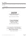
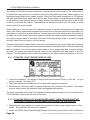
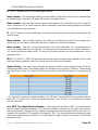
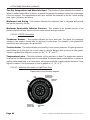
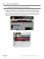
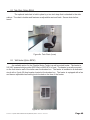
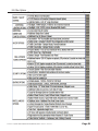
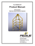
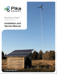
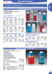
1
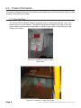
Part #123404-001 OPERATION & SERVICE MANUAL: Fiberlite POD and Fiberlite XL Splicing Trailers IS O 9 0 0 1 Ce r tifie d T.A. Pelsue Company 2500 South Tejon Street Englewood, Colorado, USA 80110 Tel. 800-525-8460 or 303-936-7432 Fax. 303-934-5581 Internet: www.pelsue.com Email: [email protected] IS O 9 0 0 1 C er tifie d S ince our inception in 1963 – the T.A. Pelsue Company has designed and manufactured high quality equipment to improve the personnel efficiency and working conditions in various underground, confined, and outdoor areas. Founded by T. Allen Pelsue, the company has established a continuing reputation for excellence in the production of fine products for a broad spectrum of industry throughout the world. Now, in our second generation of family direction, continued commitment to innovation and quality makes Pelsue a leading source of equipment for many types of confined spaces. We specialize in safety, retrieval, fall arrest, ventilation, cable placing, splicing, and maintenance nationally and abroad. With more than 70,000 square feet of facilities available, Pelsue continues the dedication that has made us pre-eminent in this field. #123404-001 - Operation & Service Manual: FiberLite (POD & XL) Trailers - Revision 02 - 02-02-2010 Page 3 Table of Contents Page 4 Section Description Page # 1.0...................................... General Information.................................. 5 1.1...........................Introduction 1.2...........................Quality Policy 1.3...........................Warranty Statement 1.4...........................Reporting Safety Defects 2.0...................................... Trailer Information.....................................8 2.1...........................Trailer Data Plates 2.2...........................Equipment Data 3.0...................................... Trailer Operation & Usage........................ 10 3.1...........................Towing Instructions 3.2...........................Operating Instructions 3.2.1...................Daily Equipment Check 3.2.2...................Starting 3.2.3...................General Operation 3.2.4...................Stopping 4.0...................................... Trailer Wiring............................................. 19 4.1...........................6 Pole Connector - Without Junction Box 4.2...........................Light/Brake Wiring - With Junction Box 4.3...........................6 Pole Connector - With Junction Box 4.4...........................7 Pole Connector - Cole Hersee 4.5...........................6 Pole Connector - Warner 4.6...........................4 POle Connector - Cole Hersee 4.7...........................7 POle Connector - RV Spade 4.6...........................Trailer Wiring Diagram 5.0...................................... Maintenance...............................................26 5.1...........................Trailer Chassis 5.2...........................Genset & Genset Installation 5.3...........................Maintenance Record 6.0...................................... Safety.......................................................... 29 6.1.......................... General Safety 6.2...........................Propane Safety 6.3...........................Tire Safety Information 7.0...................................... Troubleshooting........................................ 46 7.1...........................Electric Brakes Troubleshooting 7.2...........................Genset Troubleshooting 8.0......................................Optional Equipment.................................. 48 8.1...........................Light Bar (Option #9053 & 9012) 8.2...........................Task Chair (Option #9064) 8.3...........................Wall Heater (Option #9P40) 8.4...........................Cross Aisle Drop-In Counter (Option #9069) 8.5,,,,,,,,,,,,,,,,,,,,,,,,,,,Other Options #123404-001 - Operation & Service Manual: FiberLite (POD & XL) Trailers - Revision 02 - 02-02-2010 1.0 - General Information The following section contains general information that should be read immediately upon receipt of your Pelsue trailer. 1.1 - Introduction ISO 9001 T.A. Pelsue Company 2500 S Tejon, Englewood, Colorado, 80110, USA Telephone (303) 936-7432 Fax (303) 934-5581 Thank you and congratulations on purchasing what we feel is the world’s finest Fiberlite Series Trailer. Prior to unloading your trailer, please note the following: Upon receipt of your new Pelsue Fiberlite Series Trailer: 1. Install tongue jack, if not already installed, on the pivot mount provided at the A-frame of trailer prior to unloading from carrier. This jack is stored inside of the trailer in a cabinet module if not installed upon receipt. Corner leveling jacks may also be stored inside in a cabinet module. 2. Once trailer is safely on the ground with wheels chocked, inspect the exterior to verify damage has not occurred during transit. NOTE ANY DAMAGE ON BILL OF LANDING. 3. Install rear corner leveling jacks if required and, if selected, the optional front leveling jacks. 4. Remove any additional protective padding that may have been installed around the roof top mounted air conditioner. 5. Open genset compartment and visually inspect genset. Check the oil level prior to starting it. 6. The air conditioner, generator and base trailer carry factory warranties by their respective manufacturers. We will gladly assist with and coordinate any warranty claims you may have with any component, whether Pelsue or another manufacturer. 7. An operation & service manual is located inside of the trailer in drawer cabinet. Also provided are manuals pertaining to other pieces of installed equipment. Please make a record of the trailer VIN number, generator serial number and air conditioner serial number, a place for recording these numbers is located in section 2.1 of this manual. These numbers will aid us in identifying your trailer if future warranty or service needs are required. 8. If you have any questions or require assistance with your trailer, now or in the future, please contact us at 1-800-525-8460. 9. Thank you for purchasing your Fiberlite Series Trailer from the PELSUE COMPANY. We know it will give you many years of faithful service. #123404-001 - Operation & Service Manual: FiberLite (POD & XL) Trailers - Revision 02 - 02-02-2010 Page 5 1.2 - Quality Policy T.A. Pelsue Company Quality Policy OUR GOAL IS THE PURSUIT OF NEVER-ENDING IMPROVEMENT IN PRODUCT QUALITY AND BUSINESS SYSTEMS. METHODS TO BE EMPLOYED IN ATTAINING THIS GOAL WILL INCLUDE NEW PRODUCT QUALITY PLANNING, EMPLOYEE TRAINING, AND UTILIZATION OF EMPLOYEE INVOLVEMENT GROUPS TO SOLVE PROBLEMS. IN AN INCREASINGLY COMPETITIVE MARKETPLACE, ENSURING CUSTOMER SATISFACTION IS ONE OF THE DIFFERENTIATORS THAT SETS YOU APART FROM THE PACK AND YIELDS A COMPETITIVE ADVANTAGE. THEREFORE, WE WILL SUPPORT TOTAL CUSTOMER SATISFACTION BY IMPLEMENTING THE ISO 9001 QUALITY SYSTEM AND PROVIDING THE NECESSARY ATMOSPHERE AND TRAINING TO NURTURE THIS CONCEPT THROUGHOUT OUR ORGANIZATION. WE WILL MAKE EVERY BUSINESS DECISION AS THOUGH THE QUALITY OF THE PART OR SERVICE PROVIDED WAS DESTINED FOR OUR OWN OR OUR FAMILY’S USE. WE WILL ALWAYS THINK QUALITY FIRST. EVERY T.A. PELSUE COMPANY EMPLOYEE IS EXPECTED TO COMMIT TO THIS PHILOSOPHY IN THE PERFORMANCE OF HIS OR HER DAILY TASKS. QUALITY FIRST! T.A. PELSUE COMPANY SENIOR MANAGEMENT TEAM Page 6 #123404-001 - Operation & Service Manual: FiberLite (POD & XL) Trailers - Revision 02 - 02-02-2010 1.3 - Warranty Statement Pelsue Product Warranty: All Pelsue products are warranted against defects in materials and workmanship in accordance with their individual warranty statement. Warranty does not cover: normal wear and tear, modifications, improper storage, corrosion, or user neglect. Equally excluded from the warranty is damage due to accidents, negligence and uses for which the product was not designed. Warranty Coverage* Pelsue General Workmanship 3 years Body/Frame/Skeleton 6 years Running Gear (not including bearings or brakes) 5 years Other Structure (Doors, Windows, Interior Finish, etc.) 1 year Gensets Dependent upon Make & Model Other Components (i.e. AC, Lights, Circuit Breakers, Cabinets) 1 year Pelsue Painted or Plated FInishes 1 year Ventilation Ducts (Blower Hoses) 3 months *From date of shipment to original buyer. 1.4 - Reporting Safety Defects If you believe that your vehicle has a defect which could cause a crash or could cause injury or death, you should immediately inform the National Highway Traffic Safety Administration (NHTSA) in addition to notifying The T.A. Pelsue Company. If NHTSA receives similar complaints, it may open an investigation and if it finds that a safety defect exists in a group of vehicles, it may order a recall and remedy campaign. However, NHTSA cannot become involved in individual problems between you, your dealer, or The T.A. Pelsue Company. To contact NHTSA, you may either call the Auto Safety Hotline toll-free at 1-888-327-4236 (TTY: 1-800-424-9153); go to http://www.safercar.gov; or Write to: NHTSA, US Department of Transportation, 1200 New Jersey SE, Washington, DC 20590. You can also obtain other information about motor vehicle safety from http://www.safercar.gov. #123404-001 - Operation & Service Manual: FiberLite (POD & XL) Trailers - Revision 02 - 02-02-2010 Page 7 2.0 - Trailer Information This section will describe where to find important trailer data such as Serial Numbers. Also provided is space for recording of this data. 2.1 - Trailer Data Plates The Pelsue Fiberlite Series Trailer is equipped with two trailer data stickers, one in the interior and one on the exterior. The interior data plate is located on the side of the front upper cabinet and the exterior data plate is located on the inside of the frame rail on the tongue of the trailer. Figure 2a. Location of interior Trailer Data Plate. Page 8 Figure 2b. Location of Trailer Data Plate. #123404-001 - Operation & Service Manual: FiberLite (POD & XL) Trailers - Revision 02 - 02-02-2010 2.1 - Trailer Data Plates Continued Figure 2d. Trailer Data Plate (Record Appropriate Data Here) Note: - Portions of the above data plates have been left blank to allow information specific to each trailer to be filled in by the owner. Depending on option selected: - The GVWR of the Fiberlite with no brakes is 1356 KG (2990LBS) - The GVWR of the Fiberlite with brakes is 1588 KG (3500LBS) - The GVWR of the Fiberlite XL is 2268 KG (5000 LBS) 2.2 - Equipment Data Certain installed components have serial numbers of their own that should be recorded for future reference. Space is provided below for the recording of important serial numbers. A.C. SERIAL NO. GENSET SERIAL NO. #123404-001 - Operation & Service Manual: FiberLite (POD & XL) Trailers - Revision 02 - 02-02-2010 Page 9 3.0 - Trailer Operation & Usage 3.1 - Towing Instructions The Fiberlite Series Trailer may be equipped with either a Lunette Eye or a Ball Coupler for a hitching mechanism, depending upon selected options. Figure 3a. Lunette Eye Figure 3b. Ball Coupler Before Towing the Pelsue Fiberlite Series Trailer please follow the hitching instructions provided below. 1. To couple the trailer to the tow vehicle utilize the trailer’s tongue jack in order to vertically align the trailer’s coupler with the tow vehicle’s hitch point (the height of the eye or coupler may have to be adjusted within the hitch channel, via the two mounting bolts, in order to achieve proper vertical alignment for a level trailer towing stance). Note: The lunette eye or ball coupler supplied with your trailer is mounted within a channel allowing for height adjustment of the hitch. The hitch is fastened within this channel using 2X) 5/8-11 UNC x 5” long Grade 8 Hex Head Cap Screws and 2X) 5/8-11 UNC “Stover” Nuts. “Stover” nuts utilize a deformed thread mechanical fastening system, the nut and accompanying screw are good for a single use only! If height adjustment of hitch is needed, new Grade 8 cap screws and new ‘Stover” Nuts must be used. The new fasteners should be torqued to 135 ft-lbs. Care should be taken so as not to overtighten the fastener, any threaded fastener can fracture due to excessive tightening torque! 2. Back the tow vehicle to the trailer; Lunette Eye - Until the trailer’s lunette eye rests inside the vehicle’s open pintle hook. OR Ball Coupler - Until the trailer’s ball coupler is directly above the vehicle’s ball hitch. Page 10 #123404-001 - Operation & Service Manual: FiberLite (POD & XL) Trailers - Revision 02 - 02-02-2010 3.1 - Towing Instructions Continued 3. Lower the trailer tongue with the tongue jack until the lunette eye contacts the base of the pintle hook or until the ball coupler fully recesses onto the ball hitch. 4. Close the pintle hook or ball coupler and insert the locking pin. 5. Connect the safety chains to the tow vehicle by crossing the chains underneath the trailer tongue. Ensure chains are of proper length in order to allow for turning of the vehicle. 6. Connect the trailer light connector to the receptacle on the tow vehicle. 7. Check the operation of the breakaway device (if-equipped) and then connect the breakaway cable to secure point on the back of the tow vehicle. The breakaway device will activate the trailer brakes if the trailer becomes separated from the tow vehicle. Such a device, in operational condition, is required in most areas for such a trailer. Electric Brakes - Breakaway cable will be attached to the breakaway device (black box) located on the curb side of the trailer tongue. Figure 3c. Breakaway Device for Trailers with Electric Brakes #123404-001 - Operation & Service Manual: FiberLite (POD & XL) Trailers - Revision 02 - 02-02-2010 Page 11 3.2 - Operating Instructions The following section contains general operating instructions for proper use of your Pelsue Fiberlite Series Trailer. Refer to this for daily maintenance checks, starting and stopping instructions and operation of lights, air conditioners and other installed equipment. 3.2.1 - Daily Equipment Check Please refer to the following operating instructions prior to first operating your trailer. I. Before Starting: Daily Equipment Check a. Check fuel and oil levels, fill if necessary. b. Check connections on battery. c. Visually inspect all wires and fuel lines for damage. d. Check to make sure exhaust outlet is clear and away from all combustibles. Ensure that the silencer and piping are tight and in good condition. e. Check tire pressures and inflate as needed. 3.2.2 - Starting II. Starting a. Check control panel to be sure that all the system switches and circuit breakers are in the off position. The genset must be started in a no load condition. b. - If equipped with remote electric start: Locate the control panel or remote start panel (refer to figures 3e and 3f) inside on the front wall of your trailer, hold the Start/ Stop switch in the start (up) position for 5 seconds or until engine starts. Figure 3e Onan Interior Control panel Page 12 Figure 3f. Generac Interior Control Panel #123404-001 - Operation & Service Manual: FiberLite (POD & XL) Trailers - Revision 02 - 02-02-2010 3.2.2 - Starting Continued - If equipped with electric start: Locate the control panel on the genset. - For Onan and Generac generators: Remove access panel. Hold the Start/Stop switch in the start (up) position for 5 seconds or until the engine starts. Figure 3g. Onan Control Panel at Genset Figure 3h. Generac Control Panel at Genset. #123404-001 - Operation & Service Manual: FiberLite (POD & XL) Trailers - Revision 02 - 02-02-2010 Page 13 Page 14 #123404-001 - Operation & Service Manual: FiberLite (POD & XL) Trailers - Revision 02 - 02-02-2010 3.2.3 - General Operation III. General Operation a. Breakers: - All circuits on this trailer are breaker protected, the breaker box is located on the front interior wall. A drawing of the breaker box is shown below in figure 3i. Check breakers first when equipment does not work. Part # 103803-000 103804-000 26E-023800 26E-026200 121878-000 101218-001 100919-002 44E-017400 122635-708 122635-406 122635-103 112574-001 112576-001 121863-001 Description Item # WIRE - 10 GA, BLACK 16 WIRE - 10 GA, GREEN 15 WIRE - 10 GA, WHITE 14 WIRE - 10 GA, RED 13 CONDUIT - 1/2” FLEXIBLE, NON-METALLIC 12 PLUG - 3 POLE, 4 WIRE, 30 AMP, 125/250 VOLT, TWIST-LOCK 11 GROMMET - RUBBER, 2-1/8” ID, 2-1/2” GR.DIA. 10 PLUG - SNAP-IN-BLANK, .5” DIA, NICKEL PLATED STEEL 9 LABEL - BREAKER POSTIONS 7-8, FOST BREAKER BOX 8 LABEL - BREAKER POSITIONS 4-6, FOST BREAKER BOX 7 LABEL - BREAKER POSITIONS 1-3, FOST BREAKER BOX 6 CIRCUIT BREAKER - 20 AMP, SINGLE POLE, INDIVID TRIP 5 CIRCUIT BREAKER - 15 AMP, SINGLE POLE, INDIVID TRIP 4 CONTROL BOX ASSEMBLY - MOBILE INSTALL. W/ONAN HGJ GEN. 3 Figure 3i. Breaker Box/Control Panel b. Genset: - Your trailer can be equipped with a wide range of generators. For specific operating instructions on your generator please refer to the generator manual included with the trailer. #123404-001 - Operation & Service Manual: FiberLite (POD & XL) Trailers - Revision 02 - 02-02-2010 Page 15 3.2.3 - General Operation Continued c. Shield and Guard Carrier: Each trailer is equipped with a mounting point for the manhole shield (ring), on the curb side of the trailer, and a manhole guard (fence), on the front tongue of the trailer. Use supplied straps to hold shield and guard in place during transit. After securing shield and guard ensure that the strap tail is secured so it will not blow around. 3j. Manhole Shield Carrier 3k. Manhole Guard Carrier d. Air Conditioner: Your trailer is equipped with a 13,500 BTU, 120 VAC, rooftop mounted air conditioner. For operating instructions refer to the manual for the air conditioner, included with the trailer. Page 16 #123404-001 - Operation & Service Manual: FiberLite (POD & XL) Trailers - Revision 02 - 02-02-2010 3.2.3 - General Operation Continued #123404-001 - Operation & Service Manual: FiberLite (POD & XL) Trailers - Revision 02 - 02-02-2010 Page 17 3.2.4 - Stopping IV. Page 18 Stopping a. Turn off all system switches and circuit breakers. b. Run the genset at no load for 5 minutes to allow the engine to cool down. c. Hold the Start/Stop switch, located inside or at the genset depending on options, in the stop (down) position, or turn the key at the genset to the OFF postion, until the genset completely stops. d. Turn the fuel valve lever to the OFF position on the genset, if equipped. #123404-001 - Operation & Service Manual: FiberLite (POD & XL) Trailers - Revision 02 - 02-02-2010 4.0 - Trailer Wiring The following section contains information on the overall wiring of the trailer. 4.1 - 6 Pole Connector - Without Junction Box Shown in figure 4a is the standard plug without a junction box, included with most select series trailers Figure 4a. Wiring Diagram - Trailer Lights & Brakes (Without Junction Box) #123404-001 - Operation & Service Manual: FiberLite (POD & XL) Trailers - Revision 02 - 02-02-2010 Page 19 4.2 Light/Brake Wiring - With Junction Box The following is a diagram of the trailer wiring up to the junction box, located on the tongue of the trailer, the three sections that follow will contain three different plug configurations and the color code for them up to the junction box. Figure 4b. Wiring Diagram - Trailer Lights & Brakes (Shown up to Junction Box) Page 20 #123404-001 - Operation & Service Manual: FiberLite (POD & XL) Trailers - Revision 02 - 02-02-2010 4.3 6 Pole Connector - With Junction Box Figure 4c. Wiring Diagram - 6 Pole Round Trailer Plug #123404-001 - Operation & Service Manual: FiberLite (POD & XL) Trailers - Revision 02 - 02-02-2010 Page 21 4.4 7 Pole Connector - Cole Hersee Figure 4d. Wiring Diagram - 7 Pole Round Trailer Plug Page 22 #123404-001 - Operation & Service Manual: FiberLite (POD & XL) Trailers - Revision 02 - 02-02-2010 4.5 6 Pole Connector - Warner Figure 4e. Wiring Diagram - 6 Pole Warner Plug/Socket #123404-001 - Operation & Service Manual: FiberLite (POD & XL) Trailers - Revision 02 - 02-02-2010 Page 23 4.6 4 Pole Connector - Cole Hersee Page 24 #123404-001 - Operation & Service Manual: FiberLite (POD & XL) Trailers - Revision 02 - 02-02-2010 4.7 7 Pole Connector- RV Spade #123404-001 - Operation & Service Manual: FiberLite (POD & XL) Trailers - Revision 02 - 02-02-2010 Page 25 4.6 Trailer Wiring Diagram Figure 4f. Wiring Diagram Page 26 #123404-001 - Operation & Service Manual: FiberLite (POD & XL) Trailers - Revision 02 - 02-02-2010 4.6 Trailer Wiring Diagram Continued Figure 4f. Wiring Diagram #123404-001 - Operation & Service Manual: FiberLite (POD & XL) Trailers - Revision 02 - 02-02-2010 Page 27 5.0 - Maintenance The following section covers maintenance of the trailer and the trailer’s installed components. 5.1 Trailer Chassis Body & Frame: Pelsue Fiberlite Series Trailers are constructed utilizing an all aluminum frame and body structure. Aluminum has been chosen for its strength, lightweight, and corrosion resistance. The aluminum body structure will provide many years of reliable service while not being plagued by rust as will it’s lesser steel counterparts. The aluminum chassis will require little to no maintenance except for the occasional washing in order to remove road debris and salt spray that may prematurely weather and wear the aluminum surfaces. Running Gear: Pelsue Fiberlite Series Trailers utilize simple and reliable rubber torsion axles in a tandem setup for their running gear. The trailer hubs are equipped with an exclusive feature that allows the greasing of the axle hubs without removing the wheels or hubs from the trailer. Consult the included trailer chassis manual regarding procedures and intervals for required maintenance and service on the trailer chassis and running gear. 5.2 Genset & Genset Installation Wiring: Wiring connections between the trailer and genset and the battery and genset should be checked periodically to ensure tight and complete connections. Any loose connections, worn insulation, or broken wires must be replaced immediately. Periodically, the battery posts should be lubed with high-quality dielectric grease in order to minimize corrosion of the battery terminals. Fuel System: Fuel lines, whether gasoline or propane, should be visually inspected at regular intervals. Any chaffing of propane or fuel lines will require immediate replacement. A gasoline fuel pump (on EL & EX gasoline models) is located underneath the trailer tongue deck at the curbside of the trailer, periodically this fuel pump should be checked for damage and proper operation. Genset: Required maintenance and service intervals will vary widely between makes and models of genset. The user should consult the manufacturers genset operation manuals (included with trailer) for the required service procedures and intervals. Complete manufacturer’s factory parts, service and technical manuals are available through Pelsue for all gensets and engines. 5.3 Maintenance Record Provided on the next two pages is a maintenance record table intended for use in recording service procedures for further reference. Performed maintenance procedures can be recorded within the following table. Additional pages can be copied and inserted if desired. In addition, a decal version of the table has been supplied on the interior surface of the curbside door of the trailer, if it is preferable to record service procedures at the trailer itself. Additional maintenance record decals (part #103991-001) are available from Pelsue. Page 28 #123404-001 - Operation & Service Manual: FiberLite (POD & XL) Trailers - Revision 02 - 02-02-2010 5.3 Maintenance Record Continued See Your Generators Owners Manual for Service Requirements and Intervals Date Hours Service Performed #123404-001 - Operation & Service Manual: FiberLite (POD & XL) Trailers - Revision 02 - 02-02-2010 Initials Page 29 5.3 Maintenance Record Continued See Your Generators Owners Manual for Service Requirements and Intervals Date Page 30 Hours Service Performed Initials #123404-001 - Operation & Service Manual: FiberLite (POD & XL) Trailers - Revision 02 - 02-02-2010 6.0 - Safety The following section covers general safety guidelines to follow when using the Pelsue Fiberlite Series Trailer. 6.1 General Safety The trailer is equipped with several warning labels, please read and heed all warnings affixed to the trailer. Figure 6a. Caution Decal # 112795-001 Figure 6b. Caution Decal # 112794-001 Figure 6c. Decal # 112793-001 #123404-001 - Operation & Service Manual: FiberLite (POD & XL) Trailers - Revision 02 - 02-02-2010 Page 31 6.2 Propane Safety MANY FIBERLITE SERIES TRAILERS ARE EQUIPPED WITH PROPANE FUELED GENERATORS. THE FOLLOWING ARE SOME GENERAL SAFETY GUIDELINES TO FOLLOW WHEN WORKING WITH & AROUND PROPANE. - Propane is dangerous, as is ANY fuel because of its very nature and purpose - it is FLAMMABLE. Read and follow the safety precautions when using any propane-fueled system. - USE COMMON SENSE! Most accidents can be avoided by using common sense and concentrating on the job to be done. - AVOID SUBJECTING PROPANE TANKS TO EXCESSIVE HEAT AND HARD ABUSE. Propane tanks should never be placed close to a fire, and should be kept out of direct sunlight if possible. Exercise care in handling to avoid dropping or abusive treatment. - Prior to connecting the propane supply to any equipment, verify that the supply pressure is regulated down to the input requirements of the equipment. - ALWAYS CHECK FOR LEAKS AFTER CONNECTING OR DISCONNECTING PROPANE TANK. The distinctive odor of propane gas should alert that a connection is leaking; check for leaks by applying a solution of soapy water at each connection. NEVER CHECK FOR LEAKS WITH AN OPEN FLAME! An undetected leak can cause extreme danger as a potential explosion hazard. - Before shutting off hose-connected equipment, first turn off the fuel at the tank and allow the fuel in the hoses and piping to evacuate and burn. Then switch off the equipment. - ALWAYS KEEP THE PROPANE TANK IN AN UPRIGHT POSITION WHILE IN USE. - FOR OUTDOOR USE ONLY. Always maintain adequate ventilation when operating a propane system; the system discharges lethal carbon monoxide gases. - Keep surrounding area free of all combustible material. Never light or relight a propane system if the surrounding air is saturated with excessive gas. - Never transport or store equipment while it is connected to its fuel source. Make sure that the regulator or valve on the propane tank is tightly closed prior to transport. Always disconnect propane from system prior to transporting. - USE PROPANE FUEL ONLY. Do not use natural gas or other fuels in equipment intended only for propane fuel. NOTE: The information presented herein, while not guaranteed, was prepared by technical personnel and is true and accurate to the best of our knowledge. This information is not intended to be all-inclusive as the manner and conditions of use, handling, storage and other factors may involve other or additional safety or performance considerations. Safe handling and use remains the responsibility of the customer. No suggestions for use are intended as, and nothing herein shall be construed as, a recommendation to infringe any existing patents or to violate any Federal, State or local laws. Page 32 #123404-001 - Operation & Service Manual: FiberLite (POD & XL) Trailers - Revision 02 - 02-02-2010 6.3 Tire Safety Information This portion of the User’s Manual contains tire safety information as required by 49 CFR 575.6. Section 6.3.1 contains “Steps for Determining Correct Load Limit - Trailer”. Section 6.3.2 contains “Steps for Determining Correct Load Limit – Tow Vehicle”. Section 6.3.3 contains a Glossary of Tire Terminology, including “cold inflation pressure”, “maximum inflation pressure”, “recommended inflation pressure”, and other non-technical terms. Section 6.3.4 contains information from the NHTSA brochure entitled “Tire Safety – Everything Rides On It”. This brochure This brochure, as well as the preceding subsections, describes the following items; • Tire labeling, including a description and explanation of each marking on the tires, and information about the DOT Tire Identification Number (TIN). • Recommended tire inflation pressure, including a description and explanation of: A. Cold inflation pressure. B. Vehicle Placard and location on the vehicle. C. Adverse safety consequences of under inflation (including tire failure). D. Measuring and adjusting air pressure for proper inflation. • Tire Care, including maintenance and safety practices. • Vehicle load limits, including a description and explanation of the following items: A. Locating and understanding the load limit information, total load capacity, and cargo capacity. B. Calculating total and cargo capacities with varying seating configurations including quantitative examples showing / illustrating how the vehicles cargo and luggage capacity decreases as combined number and size of occupants’ increases. This item is also discussed in Section 3. C. Determining compatibility of tire and vehicle load capabilities. D. Adverse safety consequences of overloading on handling and stopping on tires. 6.3.1. STEPS FOR DETERMINING CORRECT LOAD LIMIT – TRAILER Determining the load limits of a trailer includes more than understanding the load limits of the tires alone. On all trailers there is a Federal certification/VIN label that is located on the forward half of the left (road) side of the unit. This certification/VIN label will indicate the trailer’s Gross Vehicle Weight Rating (GVWR). This is the most weight the fully loaded trailer can weigh. It will also provide the Gross Axle Weight Rating (GAWR). This is the most a particular axle can weigh. If there are multiple axles, the GAWR of each axle will be provided. If your trailer has a GVWR of 10,000 pounds or less, there is a vehicle placard located in the same location as the certification label described above. This placard provides tire and loading information. In addition, this placard will show a statement regarding maximum cargo capacity. Cargo can be added to the trailer, up to the maximum weight specified on the placard. The combined weight of the cargo is provided as a single number. In any case, remember: the total weight of a fully loaded trailer can not exceed the stated GVWR. For trailers with living quarters installed, the weight of water and propane also need to be considered. Page 33 #123404-001 - Operation & Service Manual: FiberLite (POD & XL) Trailers - Revision 02 - 02-02-2010 6.3 Tire Safety Information (continued) The weight of fully filled propane containers is considered part of the weight of the trailer before it is loaded with cargo, and is not considered part of the disposable cargo load. Water however, is a disposable cargo weight and is treated as such. If there is a fresh water storage tank of 100 gallons, this tank when filled would weigh about 800 pounds. If more cargo is being transported, water can be off-loaded to keep the total amount of cargo added to the vehicle within the limits of the GVWR so as not to overload the vehicle. Understanding this flexibility will allow you, the owner, to make choices that fit your travel needs. When loading your cargo, be sure it is distributed evenly to prevent overloading front to back and side to side. Heavy items should be placed low and as close to the axle positions as reasonable. Too many items on one side may overload a tire. The best way to know the actual weight of the vehicle is to weigh it at a public scale. Talk to your dealer to discuss the weighing methods needed to capture the various weights related to the trailer. This would include the weight empty or unloaded, weights per axle, wheel, hitch or king-pin, and total weight. Excessive loads and/or under inflation cause tire overloading and, as a result, abnormal tire flexing occurs. This situation can generate an excessive amount of heat within the tire. Excessive heat may lead to tire failure. It is the air pressure that enables a tire to support the load, so proper inflation is critical. The proper air pressure may be found on the certification/VIN label and/or on the Tire Placard. This value should never exceed the maximum cold inflation pressure stamped on the tire. 6.3.1.1. TRAILERS 10,000 POUNDS GVWR OR LESS Figure 6.3.1 - Tire & Loading Information Placard 1. Locate the statement, “The weight of cargo should never exceed XXX kg or XXX lbs.,” on your vehicle’s placard. See figure 6.3.1. 2. This figure equals the available amount of cargo and luggage load capacity. 3. Determine the combined weight of luggage and cargo being loaded on the vehicle. That weight may not safely exceed the available cargo and luggage load capacity. The trailer’s placard refers to the Tire Information Placard attached adjacent to or near the trailer’s VIN (Certification) label at the left front of the trailer. 6.3.1.2. TRAILERS OVER 10,000 POUNDS GVWR (NOTE: THESE TRAILERS ARE NOT REQUIRED TO HAVE A TIRE INFORMATION PLACARD ON THE VEHICLE) 1. Determine the empty weight of your trailer by weighing the trailer using a public scale or other means. This step does not have to be repeated. 2. Locate the GVWR (Gross Vehicle Weight Rating) of the trailer on your trailer’s VIN (Certification) Page 34 #123404-001 - Operation & Service Manual: FiberLite (POD & XL) Trailers - Revision 02 - 02-02-2010 6.3 Tire Safety Information (continued) label. 3. Subtract the empty weight of your trailer from the GVWR stated on the VIN label. That weigh is the maximum available cargo capacity of the trailer and may not be safely exceeded. 6.3.2. STEPS FOR DETERMINING CORRECT LOAD LIMIT – TOW VEHICLE 1. Locate the statement, “The combined weight of occupants and cargo should never exceed XXX lbs.,” on your vehicle’s placard. 2. Determine the combined weight of the driver and passengers who will be riding in your vehicle. 3. Subtract the combined weight of the driver and passengers from XXX kilograms or XXX pounds. 4. The resulting figure equals the available amount of cargo and luggage capacity. For example, if the “XXX” amount equals 1400 lbs. and there will be five 150 lb. passengers in your vehicle, the amount of available cargo and luggage capacity is 650 lbs. (1400-750 (5 x 150) = 650 lbs.). 5. Determine the combined weight of luggage and cargo being loaded on the vehicle. That weight may not safely exceed the available cargo and luggage capacity calculated in Step # 4. 6. If your vehicle will be towing a trailer, load from your trailer will be transferred to your vehicle. Consult the tow vehicle’s manual to determine how this weight transfer reduces the available cargo and luggage capacity of your vehicle. 6.3.3. GLOSSARY OF TIRE TERMINOLOGY Accessory weight - The combined weight (in excess of those standard items which may be replaced) of automatic transmission, power steering, power brakes, power windows, power seats, radio and heater, to the extent that these items are available as factory-installed equipment (whether installed or not). Bead - The part of the tire that is made of steel wires, wrapped or reinforced by ply cords and that is shaped to fit the rim. Bead separation - This is the breakdown of the bond between components in the bead. Bias ply tire - A pneumatic tire in which the ply cords that extend to the beads are laid at alternate angles substantially less than 90 degrees to the centerline of the tread. Carcass - The tire structure, except tread and sidewall rubber which, when inflated, bears the load. Chunking - The breaking away of pieces of the tread or sidewall. Cold inflation pressure - The pressure in the tire before you drive. Cord - The strands forming the plies in the tire. Cord separation - The parting of cords from adjacent rubber compounds. Cracking - Any parting within the tread, sidewall, or inner liner of the tire extending to cord Page 35 #123404-001 - Operation & Service Manual: FiberLite (POD & XL) Trailers - Revision 02 - 02-02-2010 6.3 Tire Safety Information (continued) material. CT - A pneumatic tire with an inverted flange tire and rim system in which the rim is designed with rim flanges pointed radially inward and the tire is designed to fit on the underside of the rim in a manner that encloses the rim flanges inside the air cavity of the tire. Curb weight - The weight of a motor vehicle with standard equipment including the maximum capacity of fuel, oil, and coolant, and, if so equipped, air conditioning and additional weight optional engine. Extra load tire - A tire designed to operate at higher loads and at higher inflation pressures than the corresponding standard tire. Groove - The space between two adjacent tread ribs. Gross Axle Weight Rating - The maximum weight that any axle can support, as published on the Certification / VIN label on the front left side of the trailer. Actual weight determined by weighing each axle on a public scale, with the trailer attached to the towing vehicle. Gross Vehicle Weight Rating - The maximum weight of the fully loaded trailer, as published on the Certification / VIN label. Actual weight determined by weighing trailer on a public scale, without being attached to the towing vehicle. Hitch Weight - The downward force exerted on the hitch ball by the trailer coupler. Inner liner - The layer(s) forming the inside surface of a tubeless tire that contains the inflating medium within the tire. Inner liner separation - The parting of the inner liner from cord material in the carcass. Intended outboard sidewall - The sidewall that contains a white-wall, bears white lettering or bears manufacturer, brand, and/or model name molding that is higher or deeper than the same molding on the other sidewall of the tire or the outward facing sidewall of an asymmetrical tire that has a particular side that must always face outward when mounted on a vehicle. Light truck (LT) tire - A tire designated by its manufacturer as primarily intended for use on lightweight trucks or multipurpose passenger vehicles. Load rating - The maximum load that a tire is rated to carry for a given inflation pressure. Maximum load rating - The load rating for a tire at the maximum permissible inflation pressure for that tire. Maximum permissible inflation pressure - The maximum cold inflation pressure to which a tire may be inflated. Maximum loaded vehicle weight - The sum of curb weight, accessory weight, vehicle capacity Page 36 #123404-001 - Operation & Service Manual: FiberLite (POD & XL) Trailers - Revision 02 - 02-02-2010 6.3 Tire Safety Information (continued) weight, and production options weight. Measuring rim - The rim on which a tire is fitted for physical dimension requirements. Pin Weight - The downward force applied to the 5th wheel or gooseneck ball, by the trailer kingpin or gooseneck coupler. Non-pneumatic rim - A mechanical device which, when a non-pneumatic tire assembly incorporates a wheel, supports the tire, and attaches, either integrally or separably, to the wheel center member and upon which the tire is attached. Non-pneumatic spare tire assembly - A non-pneumatic tire assembly intended for temporary use in place of one of the pneumatic tires and rims that are fitted to a passenger car in compliance with the requirements of this standard. Non-pneumatic tire - A mechanical device which transmits, either directly or through a wheel or wheel center member, the vertical load and tractive forces from the roadway to the vehicle, generates the tractive forces that provide the directional control of the vehicle and does not rely on the containment of any gas or fluid for providing those functions. Non-pneumatic tire assembly - A non-pneumatic tire, alone or in combination with a wheel or wheel center member, which can be mounted on a vehicle. Normal occupant weight - This means 68 kilograms (150 lbs.) times the number of occupants specified in the second column of Table I of 49 CFR 571.110. Occupant distribution - The distribution of occupants in a vehicle as specified in the third column of Table I of 49 CFR 571.110. Open splice - Any parting at any junction of tread, sidewall, or inner liner that extends to cord material. Outer diameter - The overall diameter of an inflated new tire. Overall width - The linear distance between the exteriors of the sidewalls of an inflated tire, including elevations due to labeling, decorations, or protective bands or ribs. Ply - A layer of rubber-coated parallel cords. Ply separation - A parting of rubber compound between adjacent plies. Pneumatic tire - A mechanical device made of rubber, chemicals, fabric and steel or other materials, that, when mounted on an automotive wheel, provides the traction and contains the gas or fluid that sustains the load. Production options weight - The combined weight of those installed regular production options weighing over 2.3 kilograms (5 lbs.) in excess of those standard items which they replace, Page 37 #123404-001 - Operation & Service Manual: FiberLite (POD & XL) Trailers - Revision 02 - 02-02-2010 6.3 Tire Safety Information (continued) not previously considered in curb weight or accessory weight, including heavy duty brakes, ride levelers, roof rack, heavy duty battery, and special trim. Radial ply tire - A pneumatic tire in which the ply cords that extend to the beads are laid at substantially 90 degrees to the centerline of the tread. Recommended inflation pressure - This is the inflation pressure provided by the vehicle manufacturer on the Tire Information label and on the Certification / VIN tag. Reinforced tire - A tire designed to operate at higher loads and at higher inflation pressures than the corresponding standard tire. Rim - A metal support for a tire or a tire and tube assembly upon which the tire beads are seated. Rim diameter - This means the nominal diameter of the bead seat. Rim size designation - This means the rim diameter and width. Rim type designation - This means the industry of manufacturer’s designation for a rim by style or code. Rim width - This means the nominal distance between rim flanges. Section width - The linear distance between the exteriors of the sidewalls of an inflated tire, excluding elevations due to labeling, decoration, or protective bands. Sidewall - That portion of a tire between the tread and bead. Sidewall separation - The parting of the rubber compound from the cord material in the sidewall. Special Trailer (ST) tire - The “ST” is an indication the tire is for trailer use only. Test rim - The rim on which a tire is fitted for testing, and may be any rim listed as appropriate for use with that tire. Tread - That portion of a tire that comes into contact with the road. Tread rib - A tread section running circumferentially around a tire. Tread separation - Pulling away of the tread from the tire carcass. Treadwear indicators (TWI) - The projections within the principal grooves designed to give a visual indication of the degrees of wear of the tread. Vehicle capacity weight - The rated cargo and luggage load plus 68 kilograms (150 lbs.) times Page 38 #123404-001 - Operation & Service Manual: FiberLite (POD & XL) Trailers - Revision 02 - 02-02-2010 6.3 Tire Safety Information (continued) the vehicle’s designated seating capacity. Vehicle maximum load on the tire - The load on an individual tire that is determined by distributing to each axle its share of the maximum loaded vehicle weight and dividing by two. Vehicle normal load on the tire - The load on an individual tire that is determined by distributing to each axle its share of the curb weight, accessory weight, and normal occupant weight (distributed in accordance with Table I of CRF 49 571.110) and dividing by 2. Weather side - The surface area of the rim not covered by the inflated tire. Wheel center member - In the case of a non-pneumatic tire assembly incorporating a wheel, a mechanical device which attaches, either integrally or separably, to the non-pneumatic rim and provides the connection between the non-pneumatic rim and the vehicle; or, in the case of a nonpneumatic tire assembly not incorporating a wheel, a mechanical device which attaches, either integrally or separably, to the non-pneumatic tire and provides the connection between tire and the vehicle. Wheel-holding fixture - The fixture used to hold the wheel and tire assembly securely during testing. 6.3.4. TIRE SAFETY - EVERYTHING RIDES ON IT The National Traffic Safety Administration (NHTSA) has published a brochure (DOT HS 809 361) that discusses all aspects of Tire Safety, as required by CFR 575.6. This brochure is reproduced in part below. It can be obtained and downloaded from NHTSA, free of charge, from the following web site: http://www.nhtsa.dot.gov/cars/rules/TireSafety/ridesonit/tires_index.html Studies of tire safety show that maintaining proper tire pressure, observing tire and vehicle load limits (not carrying more weight in your vehicle than your tires or vehicle can safely handle), avoiding road hazards, and inspecting tires for cuts, slashes, and other irregularities are the most important things you can do to avoid tire failure, such as tread separation or blowout and flat tires. These actions, along with other care and maintenance activities, can also: • • • • Improve vehicle handling Help protect you and others from avoidable breakdowns and accidents Improve fuel economy Increase the life of your tires. This booklet presents a comprehensive overview of tire safety, including information on the following topics: • Basic tire maintenance • Uniform Tire Quality Grading System • Fundamental characteristics of tires • Tire safety tips. Page 39 #123404-001 - Operation & Service Manual: FiberLite (POD & XL) Trailers - Revision 02 - 02-02-2010 6.3 Tire Safety Information (continued) Use this information to make tire safety a regular part of your vehicle maintenance routine. Recognize that the time you spend is minimal compared with the inconvenience and safety consequences of a flat tire or other tire failure. 6.3.5. SAFETY FIRST–BASIC TIRE MAINTENANCE Properly maintained tires improve the steering, stopping, traction, and load-carrying capability of your vehicle. Underinflated tires and overloaded vehicles are a major cause of tire failure. Therefore, as mentioned above, to avoid flat tires and other types of tire failure, you should maintain proper tire pressure, observe tire and vehicle load limits, avoid road hazards, and regularly inspect your tires. 6.3.5.1. FINDING YOUR VEHICLE’S RECOMMENDED TIRE PRESSURE AND LOAD LIMITS Tire information placards and vehicle certification labels contain information on tires and load limits. These labels indicate the vehicle manufacturer’s information including: • Recommended tire size • Recommended tire inflation pressure • Vehicle capacity weight (VCW–the maximum occupant and cargo weight a vehicle is designed to carry) • Front and rear gross axle weight ratings (GAWR– the maximum weight the axle systems are designed to carry). Both placards and certification labels are permanently attached to the trailer near the left front. 6.3.5.2. UNDERSTANDING TIRE PRESSURE AND LOAD LIMITS Tire inflation pressure is the level of air in the tire that provides it with load-carrying capacity and affects the overall performance of the vehicle. The tire inflation pressure is a number that indicates the amount of air pressure– measured in pounds per square inch (psi)–a tire requires to be properly inflated. (You will also find this number on the vehicle information placard expressed in kilopascals (kpa), which is the metric measure used internationally.) Manufacturers of passenger vehicles and light trucks determine this number based on the vehicle’s design load limit, that is, the greatest amount of weight a vehicle can safely carry and the vehicle’s tire size. The proper tire pressure for your vehicle is referred to as the “recommended cold inflation pressure.” (As you will read below, it is difficult to obtain the recommended tire pressure if your tires are not cold.) Because tires are designed to be used on more than one type of vehicle, tire manufacturers list the “maximum permissible inflation pressure” on the tire sidewall. This number is the greatest amount of air pressure that should ever be put in the tire under normal driving conditions. 6.3.5.3. CHECKING TIRE PRESSURE It is important to check your vehicle’s tire pressure at least once a month for the following reasons: • Most tires may naturally lose air over time. Page 40 #123404-001 - Operation & Service Manual: FiberLite (POD & XL) Trailers - Revision 02 - 02-02-2010 6.3 Tire Safety Information (continued) • Tires can lose air suddenly if you drive over a pothole or other object or if you strike the curb when parking. • With radial tires, it is usually not possible to determine underinflation by visual inspection. For convenience, purchase a tire pressure gauge to keep in your vehicle. Gauges can be purchased at tire dealerships, auto supply stores, and other retail outlets. The recommended tire inflation pressure that vehicle manufacturers provide reflects the proper psi when a tire is cold. The term cold does not relate to the outside temperature. Rather, a cold tire is one that has not been driven on for at least three hours. When you drive, your tires get warmer, causing the air pressure within them to increase. Therefore, to get an accurate tire pressure reading, you must measure tire pressure when the tires are cold or compensate for the extra pressure in warm tires. 6.3.5.4. STEPS FOR MAINTAINING PROPER TIRE PRESSURE • Step 1: Locate the recommended tire pressure on the vehicle’s tire information placard, certification label, or in the owner’s manual. • Step 2: Record the tire pressure of all tires. • Step 3: If the tire pressure is too high in any of the tires, slowly release air by gently pressing on the tire valve stem with the edge of your tire gauge until you get to the correct pressure. • Step 4: If the tire pressure is too low, note the difference between the measured tire pressure and the correct tire pressure. These “missing” pounds of pressure are what you will need to add. • Step 5: At a service station, add the missing pounds of air pressure to each tire that is underinflated. • Step 6: Check all the tires to make sure they have the same air pressure (except in cases in which the front and rear tires are supposed to have different amounts of pressure). If you have been driving your vehicle and think that a tire is underinflated, fill it to the recommended cold inflation pressure indicated on your vehicle’s tire information placard or certification label. While your tire may still be slightly underinflated due to the extra pounds of pressure in the warm tire, it is safer to drive with air pressure that is slightly lower than the vehicle manufacturer’s recommended cold inflation pressure than to drive with a significantly underinflated tire. Since this is a temporary fix, don’t forget to recheck and adjust the tire’s pressure when you can obtain a cold reading. 6.3.5.5. TIRE SIZE To maintain tire safety, purchase new tires that are the same size as the vehicle’s original tires or another size recommended by the manufacturer. Look at the tire information placard, the owner’s manual, or the sidewall of the tire you are replacing to find this information. If you have any doubt about the correct size to choose, consult with the tire dealer. 6.3.5.6. TIRE TREAD The tire tread provides the gripping action and traction that prevent your vehicle from slipping or Page 41 #123404-001 - Operation & Service Manual: FiberLite (POD & XL) Trailers - Revision 02 - 02-02-2010 6.3 Tire Safety Information (continued) sliding, especially when the road is wet or icy. In general, tires are not safe and should be replaced when the tread is worn down to 1/16 of an inch. Tires have built-in treadwear indicators that let you know when it is time to replace your tires. These indicators are raised sections spaced intermittently in the bottom of the tread grooves. When they appear “even” with the outside of the tread, it is time to replace your tires. Another method for checking tread depth is to place a penny in the tread with Lincoln’s head upside down and facing you. If you can see the top of Lincoln’s head, you are ready for new tires. 6.3.5.7. TIRE BALANCE AND WHEEL ALIGNMENT To avoid vibration or shaking of the vehicle when a tire rotates, the tire must be properly balanced. This balance is achieved by positioning weights on the wheel to counterbalance heavy spots on the wheel-and-tire assembly. A wheel alignment adjusts the angles of the wheels so that they are positioned correctly relative to the vehicle’s frame. This adjustment maximizes the life of your tires. These adjustments require special equipment and should be performed by a qualified technician. 6.3.5.8. TIRE REPAIR The proper repair of a punctured tire requires a plug for the hole and a patch for the area inside the tire that surrounds the puncture hole. Punctures through the tread can be repaired if they are not too large, but punctures to the sidewall should not be repaired. Tires must be removed from the rim to be properly inspected before being plugged and patched. 6.3.5.9. TIRE FUNDAMENTALS Federal law requires tire manufacturers to place standardized information on the sidewall of all tires. This information identifies and describes the fundamental characteristics of the tire and also provides a tire identification number for safety standard certification and in case of a recall. 6.3.5.9.1. Information on Passenger Vehicle Tires Please refer to the diagram below. Page 42 #123404-001 - Operation & Service Manual: FiberLite (POD & XL) Trailers - Revision 02 - 02-02-2010 6.3 Tire Safety Information (continued) P - The “P” indicates the tire is for passenger vehicles. Next number - This three-digit number gives the width in millimeters of the tire from sidewall edge to sidewall edge. In general, the larger the number, the wider the tire. Next number - This two-digit number, known as the aspect ratio, gives the tire’s ratio of height to width. Numbers of 70 or lower indicate a short sidewall for improved steering response and better overall handling on dry pavement. R - The “R” stands for radial. Radial ply construction of tires has been the industry standard for the past 20 years. Next number - This two-digit number is the wheel or rim diameter in inches. If you change your wheel size, you will have to purchase new tires to match the new wheel diameter. Next number - This two- or three-digit number is the tire’s load index. It is a measurement of how much weight each tire can support. You may find this information in your owner’s manual. If not, contact a local tire dealer. Note: You may not find this information on all tires because it is not required by law. M+S - The “M+S” or “M/S” indicates that the tire has some mud and snow capability. Most radial tires have these markings; hence, they have some mud and snow capability. Speed Rating - The speed rating denotes the speed at which a tire is designed to be driven for extended periods of time. The ratings range from 99 miles per hour (mph) to 186 mph. These ratings are listed below. Note: You may not find this information on all tires because it is not required by law. * For tires with a maximum speed capability over 149 mph, tire manufacturers sometimes use the letters ZR. For those with a maximum speed capability over 186 mph, tire manufacturers always use the letters ZR. U.S. DOT Tire Identification Number - This begins with the letters “DOT” and indicates that the tire meets all federal standards. The next two numbers or letters are the plant code where it was manufactured, and the last four numbers represent the week and year the tire was built. For example, the numbers 3197 means the 31st week of 1997. The other numbers are marketing codes used at the manufacturer’s discretion. This information is used to contact consumers if a tire defect requires a recall. #123404-001 - Operation & Service Manual: FiberLite (POD & XL) Trailers - Revision 02 - 02-02-2010 Page 43 6.3 Tire Safety Information (continued) Tire Ply Composition and Materials Used - The number of plies indicates the number of layers of rubber-coated fabric in the tire. In general, the greater the number of plies, the more weight a tire can support. Tire manufacturers also must indicate the materials in the tire, which include steel, nylon, polyester, and others. Maximum Load Rating - This number indicates the maximum load in kilograms and pounds that can be carried by the tire. Maximum Permissible Inflation Pressure - This number is the greatest amount of air pressure that should ever be put in the tire under normal driving conditions. 6.3.5.9.2. UTQGS Information Treadwear Number - This number indicates the tire’s wear rate. The higher the treadwear number is, the longer it should take for the tread to wear down. For example, a tire graded 400 should last twice as long as a tire graded 200. Traction Letter - This letter indicates a tire’s ability to stop on wet pavement. A higher graded tire should allow you to stop your car on wet roads in a shorter distance than a tire with a lower grade. Traction is graded from highest to lowest as “AA”,”A”, “B”, and “C”. Temperature Letter - This letter indicates a tire’s resistance to heat. The temperature grade is for a tire that is inflated properly and not overloaded. Excessive speed, underinflation or excessive loading, either separately or in combination, can cause heat build-up and possible tire failure. From highest to lowest, a tire’s resistance to heat is graded as “A”, “B”, or “C”. 6.3.5.9.3. Additional Information on Light Truck Tires Please refer to the following diagram. Page 44 #123404-001 - Operation & Service Manual: FiberLite (POD & XL) Trailers - Revision 02 - 02-02-2010 6.3 Tire Safety Information (continued) Tires for light trucks have other markings besides those found on the sidewalls of passenger tires. LT - The “LT” indicates the tire is for light trucks or trailers. ST - An “ST” is an indication the tire is for trailer use only. Max. Load Dual kg (lbs) at kPa (psi) Cold - This information indicates the maximum load and tire pressure when the tire is used as a dual, that is, when four tires are put on each rear axle (a total of six or more tires on the vehicle). Max. Load Single kg (lbs) at kPa (psi) Cold - This information indicates the maximum load and tire pressure when the tire is used as a single. Load Range - This information identifies the tire’s load-carrying capabilities and its inflation limits. 6.3.6. TIRE SAFETY TIPS Preventing Tire Damage • Slow down if you have to go over a pothole or other object in the road. • Do not run over curbs or other foreign objects in the roadway, and try not to strike the curb when parking. Tire Safety Checklist • Check tire pressure regularly (at least once a month), including the spare. • Inspect tires for uneven wear patterns on the tread, cracks, foreign objects, or other signs of wear or trauma. • Remove bits of glass and foreign objects wedged in the tread. • Make sure your tire valves have valve caps. • Check tire pressure before going on a long trip. • Do not overload your vehicle. Check the Tire Information and Loading Placard or User’s Manual for the maximum recommended load for the vehicle. #123404-001 - Operation & Service Manual: FiberLite (POD & XL) Trailers - Revision 02 - 02-02-2010 Page 45 7.0 - Troubleshooting The following section contains information on troubleshooting & diagnosing some problems that may be encountered with the trailer. 7.1 Electric Brakes Troubleshooting Problem 1. No Brakes 2. Intermittent or Surging Brakes 3. Weak Brakes 4. Grabby or Locking Brakes 5. Dragging Brakes Possible Cause Remedy a. Open circuit a. Check for broken wires, loose connections, improper grounding, faulty connector plug between trailer and vehicle. b. Improperly wired or inoperative controller b. Rewire controller. Check controller operation. c. Poor brake adjustment c. Adjust brakes d. Short circuit d. Check electrical circuit a. Inadequate trailer ground a. Check for proper grounding b. Broken magnet lead wire b. Check magnet, replace if necessary c. Loose wheel bearing c. Check and adjust bearing a. Poor connection a. Check for clean & tight connections b. Poor ground b. Do not ground through trailer hitch c. Short circuit c. Check electrical circuit d. Worn or defective magnet d. Replace e. Poor brake adjustment e. Adjust brakes a. Grease on lining a. Check for contamination. Replace seal and lining. b. Controller not modulating b. Replace c. Loose parts in brakes c. Check for broken springs, loose rivets, etc. a. Brakes not adjusted a. Check brake adjustment, adjust if necessary b. Electrical defect in controller b. Correct or replace c. Hydraulic defect in controller c. Correct or replace Figure 7a. Electric Brake Troubleshooting Table Page 46 #123404-001 - Operation & Service Manual: FiberLite (POD & XL) Trailers - Revision 02 - 02-02-2010 7.2 Genset Troubleshooting Troubleshooting procedures will vary widely between different makes and models of genset. The appropriate genset owner’s manual, supplied with the trailer, should be consulted in order to correctly diagnose engine and/or generator problems. Onan CMM Models: Onan CMM model gensets are the most commonly installed units on Pelsue Fiberlite Series Trailers. Onan CMM models are programmed with a comprehensive set of diagnostic and troubleshooting codes internally. These codes are displayed via a series of flashing lights displayed on the genset’s primary start/stop switch. This switch can be observed by removing the access panel located at the front of the genset. Instructions for observing and defining the troubleshooting codes are supplied in the “troubleshooting” section of the Onan Operator’s Manual supplied with the trailer. #123404-001 - Operation & Service Manual: FiberLite (POD & XL) Trailers - Revision 02 - 02-02-2010 Page 47 8.0 - Optional Equipment 8.1: Light Bar (Option #9053 [36” wide] & Option #9012 [48” wide]) The Fiberlite Series Trailers can be equipped with an optional rear LED safety light bar. The light bar is mounted above the door and has a control box located underneath the rear upper cabinet. To operate the light bar simply flip the on switch and choose setting desired. The light bar will run off the battery, so there is no need to start the genset when using light bar for short periods of time. If light bar is not working check 20 amp pushbutton cicrucit breaker located within the 12VDC breaker box. Figure 8a. Trailer with Light Bar Figure 8b. Interior Light Bar control box Page 48 #123404-001 - Operation & Service Manual: FiberLite (POD & XL) Trailers - Revision 02 - 02-02-2010 8.2 Task Chair (Option #9064) The optional task chair is held in place by a two inch strap that is attached to the side cabinet. The chair is leather and features an adjustable seat and back. Secure chair before transit. Figure 8c. Task Chair (loose) 8.3 Wall Heater (Option #9P40) An available option for the Fiberlite Series Trailer is a wall mounted heater. The heater is 240 VAC powered and provides 2000 Watt or 6820 BTU of heat. The heater is usually mounted on the front interior wall of the trailer near the breaker box. The heater is installed on a dedicated circuit with a 2-pole 20 Amp breaker located at the breaker box. The heater is equipped with a fan and has an adjustable heat setting knob located on the face of the heater. Figure 8d. Wall Mounted Heater #123404-001 - Operation & Service Manual: FiberLite (POD & XL) Trailers - Revision 02 - 02-02-2010 Page 49 8.4 Cross Aisle Drop-in Counter The optional cross aisle table is very easy to install and adds an extra five square feet of movable work space to the trailer. To install the table simply slide the end with out a bracket in to the channel as shown in figure 8e. Then rest the bracketed end on the top of the main counter top. Once installed slide counter to desired position. Figure 8e. Slide end in to channel Figure 8f. Cross Aisle Counter (installed) Page 50 #123404-001 - Operation & Service Manual: FiberLite (POD & XL) Trailers - Revision 02 - 02-02-2010 8.5 Other Options Description #123404-001 - Operation & Service Manual: FiberLite (POD & XL) Trailers - Revision 02 - 02-02-2010 Option # Page 51 T.A. Pelsue Company 2500 South Tejon Street, Englewood, Colorado, USA 80110 Toll free 800-525-8460 or 303-936-7432 Fax. 303-934-5581 Internet: www.pelsue.com Email: [email protected]