1
INDEX
original copywriter 1987
revised 2001 - printed 2002
A
INDEX
MARES SERVICE MANUAL
CONTENTS
Last
revision
INTRODUCTION
GENERAL INTRODUCTION
MARES SERVICE MANUAL
Note
I
I
1998
1998
III
III
III
IV
V
VI
VI.a
1998
1998
1998
1998
1998
1998
2002
NEW
VI.b
2002
NEW
VI.c
VI.d
VI.e
VI.f
VI.g
2002
2002
2002
2002
2002
NEW
NEW
NEW
NEW
NEW
N 1-1
N 1-2
N 1-3
N 1-4
1998
1998
1998
1998
K 1-1
K 1-2
K 1-5
1998
1998
1998
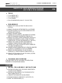
REGULATOR SERVICE
GENERAL
SERIALIZATION / WARRANTY
ROUTINE CARE
SERVICE REQUIREMENTS
SET OF TOOLS FOR REGULATORS MAINTENACE
SPECIAL TOOL KIT
O-RING TABLE 1° E 2° STAGE
O-RING TABLE H.U.B. AIR TRIM-PNEUMATICAL
INFLATOR PNEUMATICAL DUMP VALVES
O-RING TABLE H.U.B. - HOSES/MANIFOLDS ORAL INFLATOR - DEPTH GAUGE
O-RING TABLE BC - AIRLOCK
O-RING TABLE VALVE SETS
O-RING TABLE SPEARGUNS
O-RING TABLE LIGHTS
NITROX STATEMENT
CONVERSION PROCEDURES
DISASSEMBLY/CLEANING/DRYING/INSPECTING
LUBRIFICATION/REASSEMBLY
ADJUSTMENT
BTM5
F 1-1
F 1-3
F 1-3
F 1-4
F 1-5
F 1-7
F 1-7
F 1-8
F 1-9
F 1-10
F 1-11
F 1-12
F 1-13
F 1-14
F 1-15
2002
1998
1998
1998
1998
1998
1998
1998
1998
2000
2002
2002
2002
2002
2002
2002
F 2-1
F 2-2
F 2-3
F 2-4
F 2-5
F 2-7
F 2-8
F 2-9
F 2-10
F 2-11
1998
1998
1998
1998
1998
1998
2000
2002
2002
2002
1998
1998
1998
1998
1998
1998
1997
2000
2002
2002
2002
2002
F 4-1
F 4-1
F 4-2
F 4-3
F 4-3
F 4-6
F 4-7
1998
1998
1998
1998
1998
1998
1991
F 5-1
F 5-2
F 5-3
F 5-5
1998
1998
1998
1997
F 6-1
F 6-1
F 6-2
F 6-3
F 6-4
F 6-5
F 6-6
F 6-7
1998
1998
1998
1998
1998
1998
2000
2002
F 7-1
F 7-2
F 7-3
2002
2002
2002
F 8-1
2002
BTM3
S 1-1
S 1-2
S 1-3
2000
1998
1998
1998
S 1-4
S 1-5
S 1-6
S 1-7
S 1-8
S 1-9
S 1-10
S 1-11
1998
1998
1998
2000
2002
2002
2002
2002
NEW
NEW
NEW
DISASSEMBLY
MR 10 DIN VERSION DISASSEMBLY
CLEANING
INSPECTION
REASSEMBLY
MR 10 DIN VERSION REASSEMBLY
MR10 DRAWING AND PARTS LIST
R1 - R2 FIRST STAGE SERVICE
NEW
DISASSEMBLY
DISASSEMBLY (replacing stage 6)
CLEANING
INSPECTION
REASSEMBLY
R1 - R2 DIN VERSION REASSEMBLY
R1 - R2 DRAWING AND PARTS LIST
R2 DRAWING AND PARTS LIST
R2 TABLE
NEW
FIRST STAGE ADJUSTMENT
INTERMEDIATE PRESSURE
ADJUSTMENT IN DIAPHRAGM
ADJUSTMENT IN PISTON
NEW
FIRST STAGE TROUBLE SHOOTING
NEW
NEW
NEW
MR 16 - V 16 - VX 16 - TI PLANET
FIRST STAGE SERVICE
DISASSEMBLY
MR 16-V16 DIN VERSION / DISASSEMBLY
CLEANING / INSPECTION
REASSEMBLY
MR 16-V16 DIN VERSION / REASSEMBLY
MR 16 - V16 DRAWING AND PARTS LIST
MR 16 - V16 DRAWING AND PARTS LIST
V 16 TABLE
TI PLANET DRAWING AND PARTS LIST
TI PLANET TABLE
F 3-1
F 3-1
F 3-2
F 3-3
F 3-4
F 3-5
F 3-6
F 3-7
F 3-8
F 3-9
F 3-10
F 3-11
MR 10 FIRST STAGE SERVICE
DISASSEMBLY
CLEANING / INSPECTION
REASSEMBLY
MR 12 II DRAWING AND PARTS LIST
MR 22 - RUBY (TITANIUM) - ABYSS - V32
FIRST STAGE SERVICE
TECHNICAL BULLETIN MARES 5
DISASSEMBLY
RUBY DIN VERSION / DISASSEMBLY
CLEANING
INSPECTION
REASSEMBLY
RUBY DIN VERSION / REASSEMBLY
ADJUSTING INTERMEDIATE PRESSURE
MR22- RUBY DRAWING AND PARTS LIST
RUBY SCHEMATIC AND PARTS LIST
RUBY DRAWING
RUBY TABLE
ABYSS DRAWING AND PARTS LIST
ABYSS TABLE
V 32 DRAWING
V 32 TABLE
DISASSEMBLY
MR 12-V12 DIN VERSION / DISASSEMBLY
CLEANING
INSPECTION
REASSEMBLY
MR 12-V12 DIN VERSION REASSEMBLY
MR12-V12 DRAWING AND PARTS LIST
MR12-MRX 12 DRAWING AND PARTS LIST
MR12-MRX 12 DRAWING
MR12 - TABLE
MR12 LONG DRAWING
MR12 LONG TABLE
Note
MR 12 II FIRST STAGE SERVICE
CWD KIT FIRST STAGE
COLD WATER DIVING KIT (CWD)
RUBY-MR22-MR16-V16
MR12-V12
Last
revision
MR12 - MRX12 - V12 - MR12 LONG
FIRST STAGE SERVICE
NEW
NEW
RUBY-ABYSS-VOLTREX-ORBITER
SECOND STAGE SERVICE
TECHNICAL BULLETIN
DISASSEMBLY
CLEANING / INSPECTION
REASSEMBLY
RUBY/ABYSS/VOLTREX
SECOND STAGE ADJUSTMENT
FINAL ASSEMBLY
R.A.V. DRAWING AND PARTS LIST
RUBY-ORBITER DRAWING AND PARTS LIST
RUBY TABLE
ORBITER TABLE
ABYSS-OCTOPUS ABYSS DRAWING AND PARTS LIST
ABYSS - OCTOPUS ABYSS TABLE
NEW
NEW
NEW
B
INDEX
original copywriter 1987
revised 2001 - printed 2002
INDEX
MARES SERVICE MANUAL
CONTENTS
Last
revision
Note
XTR-XL-AKROS-TI PLANET-EPOS
SECOND STAGE SERVICE
DISASSEMBLY
CLEANING
INSPECTION
REASSEMBLY
ADJUSTMENT AND FINAL ASSEMBLY
PROCEDURE A
PROCEDURE B
AKROS DRAWING AND PARTS LIST
AKROS TABLE
XTR TABLE
XL TABLE
TI PLANET DRAWING AND PARTS LIST
TI PLANET TABLE
EPOS DRAWING AND PARTS LIST
EPOS TABLE
S 2-1
S 2-2
S 2-3
S 2-4
S 2-6
S 2-7
S 2-8
S 2-10
S 2-11
S 2-12
S 2-13
S 2-14
S 2-15
S 2-16
S 2-17
1998
1998
1998
1998
1998
1998
1998
1998
2002
2002
2002
2002
2002
2002
2002
BTM1
BTM2
S 3-1
S 3-2
S 3-3
S 3-4
S 3-6
S 3-7
S 3-8
S 3-9
S 3-10
S 3-11
2000
2000
1998
1998
1998
1998
1998
1998
1998
1998
2000
2002
S 4-1
S 4-2
S 4-2
S 4-3
S 4-4
S 4-6
1998
1998
1998
1998
1998
1998
S 5-1
S 5-2
S 5-2
S 5-3
S 5-4
S 5-6
1998
1998
1998
1998
1998
1998
S 6-1
S 6-2
S 6-3
S 6-4
S 6-6
1998
1998
1998
1998
1998
S 6-7
S 6-7
S 6-8
S 6-10
S 6-11
1998
1998
1998
1998
1998
III - II SECOND STAGE SERVICE
DISASSEMBLY
CLEANING
INSPECTION
REASSEMBLY
ADJUSTMENT FINAL ASSEMBLY
III DRAWING AND PARTS LIST
NAVY SECOND STAGE SERVICE
DISASSEMBLY
CLEANING
INSPECTION
REASSEMBLY
NAVY SECOND STAGE ADJUSTMENT
NAVY DRAWING AND PARTS LIST
BETA - MR10 SECOND STAGE SERVICE
DISASSEMBLY
CLEANING
INSPECTION
REASSEMBLY
BETA SECOND STAGE ADJUSTMENT
CHANGING THE HOSE CONNECTION
FROM RIGHT TO LEFT
DISASSEMBLY
REASSEMBLY
BETA DRAWING AND PARTS LIST
MR10 DRAWING AND PARTS LIST
Note
AXIS - OCTOPUS AXIS SECOND STAGE SERVICE
DISASSEMBLY
CLEANING
INSPECTION
REASSEMBLY
FINAL ADJUSTMENTS
ADJUSTING THE INTERMEDIATE PRESSURE
FINAL ASSEMBLY
AXIS DRAWING
AXIS TABLE
NEW
NEW
NEW
NEW
NEW
NIKOS SECOND STAGE SERVICE
TECHNICAL BULLETIN
TECHNICAL BULLETIN
DISASSEMBLY
CLEANING
INSPECTION
REASSEMBLY
ADJUSTMENT FINAL ASSEMBLY
PROCEDURE A
PROCEDURE B
NIKOS DRAWING AND PARTS LIST
NIKOS 2000 DRAWING AND PARTS LIST
NIKOS TABLE
Last
revision
S 7-1
S 7-2
S 7-3
S 7-4
S 7-6
S 7-7
S 7-8
S 7-10
S 7-11
2002
2002
2002
2002
2002
2002
2002
2002
2002
NEW
NEW
NEW
NEW
NEW
NEW
NEW
NEW
NEW
2002
2002
2002
2002
2002
2002
2002
2002
2002
2002
2002
NEW
NEW
NEW
NEW
NEW
NEW
NEW
NEW
NEW
NEW
NEW
PROTON - PROTON XL SECOND STAGE SERVICE
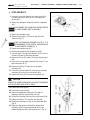
DISASSEMBLY
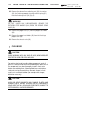
CLEANING
INSPECTION
REASSEMBLY
ASSEMBLING THE DEMAND LEVER
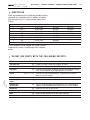
FINAL ASSEMBLY
FINAL ADJUSTMENTS
PROTON DRAWING
PROTON TABLE
PROTON XL DRAWING
PROTON XL TABLE
S 8-1
S 8-2
S 8-3
S 8-4
S 8-5
S 8-7
S 8-8
S 8-10
S 8-11
S 8-12
S 8-13
SECOND STAGES FINAL CHECKS AND ADJUSTMENT
2002
SECOND STAGES TROUBLE SHOOTING
2002
LP INFLATOR SERVICE
NEW
GENERAL
SERIALIZATION
WARRANTY
ROUTINE CARE
SERVICE REQUIREMENTS
SPECIAL TOOL ERGO
VII
VII
VII
VII
VII
VIII
1998
1998
1998
1998
1998
1998
B 1-1
B 1-1
B 1-1
B 1-2
B 1-2
B 1-2
B 1-2
B 1-3
B 1-3
B 1-5
B 1-5
B 1-6
B 1-6
B 1-7
B 1-8
1998
1998
1998
1998
1998
1998
1998
1998
1998
1998
1998
1998
1998
1998
1998
B 1-8
B 1-8
B 1-9
B 1-10
1998
1998
1998
1993
MULTI AIR - INTERNATIONAL INFLATOR
DISASSEMBLING THE SECOND STAGE
DISASSEMBLING THE INFLATOR UNIT
DISASSEMBLING THE QUICK COUPLING
DISASSEMBLING THE DEFLATION GROUP
DISASSEMBLING THE LP INFLATOR C.G.
DISASSEMBLING THE R.E. VALVE
DISASSEMBLING THE CORRUGATED HOSE
CLEANING
INSPECTION
REASSEMBLY
ASSEMBLING THE LP INFLATOR C.G.
ASSEMBLING THE DEFLATION GROUP
ASSEMBLING THE COUPLING
ASSEMBLING THE R.E. VALVE GROUP
ASSEMBLING THE CORRUGATED HOSE
ASSEMBLING THE SECOND STAGE
(Multi Air version only)
ASSEMBLING THE CORR. HOSE ON THE BC
FINAL CHECKS
MULTI AIR - INT. INFLATOR DRAWING
INDEX
original copywriter 1987
revised 2001 - printed 2002
C
INDEX
MARES SERVICE MANUAL
CONTENTS
Last
revision
ERGO LP INFLATOR
LP INFLATOR REMOVAL
DISASSEMBLY
CLEANING
INSPECTION
REASSEMBLY
LP INFLATOR INSTALLATION
FINAL INSPECTION
ERGO LP DRAWING AND PARTS LIST
ERGO INFLATOR ASSY WITH R.E. VALVE
DRAWING AND PARTS LIST
ERGO LP DRAWING
ERGO INFLATOR ASSY WITH R.E. VALVE TABLE
B 2-1
B 2-1
B 2-3
B 2-3
B 2-4
B 2-6
B 2-7
B 2-8
Note
TRIGGER SENSITIVITY ADJUSTMENT
SAFETY INSPECTION
POWER REGULATOR INSPECTION
SPEARGUN STEN (Pipin line) DRAWING
AND PARTS LIST
1998
1998
1998
1998
1998
1998
1998
1998
B 2-9
B 2-10
B 2-11
2000
2002
2002
B 3-1
B 4-1
1998
1998
IX
IX
IX
IX
X
XI
1998
1998
1998
1998
1998
1998
SPEARGUN TROUBLESHOOTING
NEW
GENERAL INFORMATION GUN SERVICE
GENERAL
SERIALIZATION
WARRANTY
ROUTINE CARE
SERVICE REQUIREMENTS
SPECIAL TOOL KIT
CYRANO/SPARK/STEN 2001 PNEUMATIC SPEARGUNS
DISASSEMBLY
G 1-1
CLEANING
G 1-4
INSPECTION
G 1-4
REASSEMBLY
G 1-5
TAHITIAN SHAFT SERVICE
G 1-10
DISASSEMBLY
G 1-10
REASSEMBLY
G 1-10
PRESSURIZING
G 1-11
PRESSURIZING USING MARES
GUN CHARGING YOKE
G 1-11
PRESSURIZING USING MARES HAND PUMP G 1-12
INSPECTION AND ADJUSTMENT
G 1-13
O-RING INSPECTION
G 1-13
TRIGGER STROKE INSPECTION
G 1-13
TRIGGER SENSITIVITY ADJUSTMENT
G 1-14
SAFETY BAR INSPECTION
G 1-14
POWER REGULATOR INSPECTION
G 1-14
CYRANO DRAWING AND PARTS LIST
G 1-15
SPARK (Pipin line) DRAWING AND PARTS LIST G 1-16
STEN 2001 SERIES DRAWING
G 1-17
STEN 2001 SERIES DRAWING
G 1-18
STEN 2001 SERIES TABLE
G 1-19
1998
1998
2002
2002
1998
1998
1998
1998
1998
2002
1998
1998
1998
1998
1998
1998
1998
1998
2002
2002
2002
COMPETITION PNEUMATIC SPEARGUN
DISASSEMBLY
CLEANING
INSPECTION
REASSEMBLY
PRESSURIZING
PRESSURIZING USING MARES
GUN CHARGING YOKE
PRESSURIZING USING MARES HAND PUMP
INSPECTION AND ADJUSTMENT
O-RING INSPECTION
TRIGGER STROKE INSPECTION
G 2-1
G 2-4
G 2-4
G 2-5
G 2-9
1998
1998
1998
1998
1998
G 2-10
G 2-10
G 2-11
G 2-12
G 2-12
1998
1998
1998
1998
1998
G 2-12
G 2-13
G 2-13
1998
1998
1998
G 2-11
1998
G 3-1
2002
INTEGRATED SYSTEM H.U.B.
TROUBLESHOOTING
MULTI AIR - INTERNATIONAL INFLATOR
ERGO INFLATOR TROUBLE SHOOTING
Last
revision
NEW
NEW
NEW
TECHNICAL BULLETIN
BTM4
DISASSEMBLIES
DISASSEMBLY OF THE 1ST STAGE FROM
INTEGRATED SYSTEM
H 1-1
DISASSEMBLY OF H.U.B. BAG
H 1-1
DISASSEMBLY OF 4-WAY MANIFOLD
H 1-1
DISASSEMBLY OF BACKPACK
H 1-2
DISASSEMBLY OF 7-WAY MANIFOLD
H 1-2
DISASSEMBLY OF TANK SUPPORT PLATE
H 1-3
DISASSEMBLY OF MECHANICAL
OVERPRESSURE VALVES
H 1-3
DISASSEMBLY OF INFLATING ORAL PIPE
H 1-4
DISASSEMBLY OF H.U.B. PNEUMATIC SYSTEM
DISASSEMBLY OF PNEUMATIC CONTROL
H 1-4
DISASSEMBLY OF PNEUMATIC DUMP VALVES
EXTERNAL BEZEL
H 1-5
DISASSEMBLY OF PNEUMATIC SYSTEM
INTERNAL SUPPORTS FROM BAG
H 1-6
DISASSEMBLY OF BOTTOM PNEUMATIC DUMP
VALVE INTERNAL SUPPORT
H 1-6
DISASSEMBLY OF TOP PNEUMATIC DUMP
VALVE INTERNAL SUPPORT
H 1-7
DISASSEMBLY OF PNEUMATIC CONTROL
INTERNAL SUPPORT
H 1-7
DISASSEMBLY OF PNEUMATIC SYSTEM
INTERNAL SHEATHING
H 1-7
CLEANING
H 1-8
INSPECTION
H 1-8
PNEUMATIC CONTROL
H 1-8
PNEUMATIC VALVES
H 1-9
7-WAY MANIFOLD/HOSES
H 1-10
4-WAY MANIFOLD
H 1-10
ORAL PIPE
H 1-11
OVERPRESSURE VALVE
H 1-11
REASSEMBLY
H 1-11
PNEUMATIC SYSTEM REASSEMBLY
H 1-12
REASSEMBLY OF INTERNAL SHEATHING OF
INTEGRATED SYSTEM
H 1-12
REASSEMBLY OF INTERNAL SUPPORT OF
PNEUMATIC CONTROL
H 1-12
REASSEMBLY OF INTERNAL SUPPORT OF TOP
PNEUMATIC DUMP VALVE
H 1-12
REASSEMBLY OF INTERNAL SUPPORT OF
BOTTOM PNEUMATIC DUMP VALVE
H 1-13
REASSEMBLY OF PNEUMATIC DUMP VALVES
EXTERNAL BEZEL
H 1-14
REASSEMBLY OF PNEUMATIC CONTROL BODY H 1-14
REASSEMBLY OF PNEUMATIC CONTROL
H 1-16
REASSEMBLY OF BAG
H 1-16
REASSEMBLY OF INFLATION PIPE
H 1-16
REASSEMBLY OF MECHANIC OVERPRESSURE
VALVES
H 1-17
2000
2002
2000
2000
2000
2000
2000
2000
2000
2000
2000
2000
2000
2000
2000
2000
2000
2000
2000
2000
2000
2000
2000
2000
2000
2000
2000
2000
2000
2000
2000
2000
2000
2000
2000
2000
2000
Note
NEW
D
INDEX
original copywriter 1987
revised 2001 - printed 2002
INDEX
MARES SERVICE MANUAL
CONTENTS
Last
revision
REASSEMBLY OF TANK PLATE SUPPORT
H 1-18
REASSEMBLY OF 7-WAY MANIFOLD SYSTEM H 1-19
REASSEMBLY OF TANK PLATE SUPPORT + 7-WAY
MANIFOLD ON INTEGRATED SYSTEM
H 1-20
REASSEMBLY OF BACK PACK
H 1-20
REASSEMBLY 4-WAY MANIFOLD AND
SECONDS STAGES
H 1-21
REASSEMBLY OF 1ST STAGE
H 1-22
TESTS
H 1-22
TEST OF PNEUMATIC SYSTEM
H 1-22
A) PNEUMATIC CONTROL BODY
H 1-22
B) PNEUMATIC DUMP VALVES
H 1-23
TEST OF BAG
H 1-23
C) MECHANICAL OVERPRESSURE VALVES
H 1-23
D) BAG
H 1-24
TEST OF INTEGRATED SYSTEM ASSEMBLY
H 1-24
TEST OF DISTRIBUTORS / HOSES
H 1-25
F) DISASSEMBLY
H 1-25
G) REASSEMBLY
H 1-26
H.U.B. MARES DRAWING AND PARTS LIST
H 1-27
H.U.B. MARES TABLE
H 1-28
H.U.B. MARES TABLE
H 1-29
PNEUMATIC DISCHARGE VALVE H.U.B.
DRAWING AND PARTS LIST
H 1-30
PNEUMATIC DISCHARGE VALVE H.U.B. TABLE H 1-31
PNEUMATIC CONTROL H.U.B. DRAWING AND
PARTS LIST
H 1-32
PNEUMATIC CONTROL H.U.B. TABLE
H 1-33
H.U.B. CENTURY DRAWING
H 1-34
H.U.B. CENTURY TABLE
H 1-35
H.U.B. AVANTGARDE DRAWING
H 1-36
H.U.B. AVANTGARDE TABLE
H 1-37
H.U.B AVANTGARDE PNEUMATIC
CONTROL DRAWING
H 1-38
H.U.B AVANTGARDE PNEUMATIC
CONTROL TABLE
H 1-39
Note
Last
revision
Note
ACCESSORIES
2000
2000
AIRLOCK
DISASSEMBLY
DISASSEMBLING THE AIRLOCK SYSTEM
DISASSEMBLING THE QUICK COUPLING
CHECK VALVE
CLEANING
INSPECTION
REASSEMBLY
ASSEMBLING THE QUICK COUPLING
CHECK VALVE
ASSEMBLING THE AIRLOCK SYSTEM
CHECKS AND INSPECTIONS
AIRLOCK DRAWING
AIRLOCK TABLE
2000
2000
2000
2000
2000
2000
2000
2000
2000
2000
2000
2000
2000
2000
2000
2000
2002
2002
NEW
2002
2002
NEW
2002
2002
2002
2002
2002
2002
NEW
NEW
NEW
NEW
NEW
2002
NEW
2002
NEW
I 1-1
I 1-1
2002
2002
NEW
NEW
I 1-4
I 1-4
I 1-5
I 1-6
2002
2002
2002
2002
NEW
NEW
NEW
NEW
I 1-6
I 1-7
I 1-10
I 1-12
I 1-13
2002
2002
2002
2002
2002
NEW
NEW
NEW
NEW
NEW
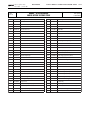
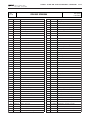
O-RING REFERENCE CHART
original copywriter 1987
revised 2001 - printed 2002
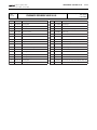
FIRST STAGES
O-RING TYPE - REFERENCE
2012
-
46110101
2018
-
46110203
106
-
O-RING TYPE - REFERENCE
2031
-
46110107
108
-
46110108
2050
-
46110211
3118
-
46110176
46110106
115
-
46110117
2100
-
46110224
SECOND STAGES
O-RING TYPE - REFERENCE
106
-
46110106
7x2
-
46200154
2068
2062
2037
-
-
-
O-RING TYPE - REFERENCE
2025
-
46110205
2043
-
46110215
2050
-
46110211
2075
-
46110243
46110225
46110220
46110110
VI.a
VI.b
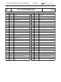
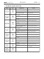
O-RING REFERENCE CHART
original copywriter 1987
revised 2001 - printed 2002
H.U.B. AIR TRIM - PNEUMATICAL INFLATOR
O-RING TYPE - REFERENCE
2007
-
46110213
3x1
-
46200154
2015
-
46110102
2062
-
46110220
2050
-
O-RING TYPE - REFERENCE
3156
-
47110270
3231
-
46110265
46110211
H.U.B. AIR TRIM - PNEUMATICAL DUMP VALVES
O-RING TYPE - REFERENCE
3x1
-
47110272
2015
-
46110102
2037
-
46110110
O-RING TYPE - REFERENCE
3231
-
46110265
O-RING REFERENCE CHART
original copywriter 1987
revised 2001 - printed 2002
H.U.B. - HOSES / MANIFOLDS
O-RING TYPE - REFERENCE
2-003
-
46110242
2025
-
46110205
2031
-
46110107
2043
-
46110215
O-RING TYPE - REFERENCE
106
-
46110106
108
-
46110108
114
-
46110114
H.U.B. - ORAL INFLATOR
O-RING TYPE - REFERENCE
3100
-
47110271
O-RING TYPE - REFERENCE
2056
-
46110210
DEPTH GAUGE
O-RING TYPE - REFERENCE
108
-
46110108
O-RING TYPE - REFERENCE
2-003
-
46110242
VI.c
VI.d
O-RING REFERENCE CHART
original copywriter 1987
revised 2001 - printed 2002
BUOYANCY COMPENSATORS
O-RING TYPE - REFERENCE
O-RING TYPE - REFERENCE
106
-
46110106
2031
-
46110107
2-109
-
46110241
115
-
46110117
2081
-
46110221
2056
-
46110210
AIRLOCK
O-RING TYPE - REFERENCE
O-RING TYPE - REFERENCE
106
-
46110106
2010
-
46110210
2068
-
46110225
2025
-
46110205
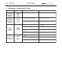
O-RING REFERENCE CHART
original copywriter 1987
revised 2001 - printed 2002
VALVE SETS
O-RING TYPE - REFERENCE
3050
2056
4100
4106
-
-
-
-
46110119
O-RING TYPE - REFERENCE
2031
-
46110107
2025
-
46110205
2050
-
46110211
2043
-
46110211
117
-
46110300
2012
-
46110101
46110210
46110216
46110216
VI.e
VI.f
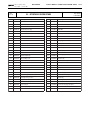
O-RING REFERENCE CHART
original copywriter 1987
revised 2001 - printed 2002
SPEARGUNS
O-RING TYPE - REFERENCE
2-003
-
46110242
R/1
-
46110201
2007
-
46110213
2015
-
46110102
106
-
46110106
2031
-
46110107
2062
-
46110220
122 BIS -
46110206
O-RING TYPE - REFERENCE
2037
-
46110110
3062
-
46110228
3056
-
46110227
2106
-
46110245
-
46110208
SPECIAL
original copywriter 1987
revised 2001 - printed 2002
O-RING REFERENCE CHART
LIGHTS
O-RING TYPE - REFERENCE
O-RING TYPE - REFERENCE
2025
-
46110205
2-109
-
46110241
2031
-
46110107
3243 - 45200064
4400 - 46110117
4387 - 46110170
4087 - 46110172
3162 - 46110219
200-212-8854 - 46110173
2-153 - 46110240
VI.g
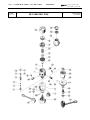
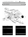
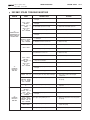
MR22-RUBY TIT.
ABYSS - V32
FIRST STAGE
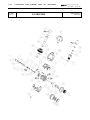
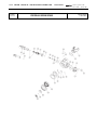
MR22 -RUBY(TITANIUM) ABYSS -V32 FIRST STAGE
TECHNICAL BULLETIN
original copywriter 1987
revised 03.13.02 - printed 2002
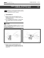
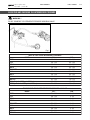
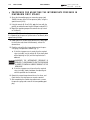
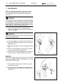
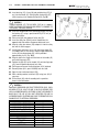
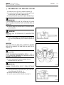
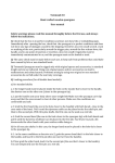
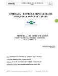
SUBJECT: ASSEMBLING - DISASSEMBLING THE V32
1ST STAGE CAP (ref. Tab. n. 21of 14/03/02)
NOTE
BTM5 5-1
BTM5
CARRY OUT THE FOLLOWING OPERATIONS BEFORE
THE PROCEDURE DESCRIBED IN STEP 16 OF THE
CORRESPONDING SERVICE MANUAL.
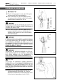
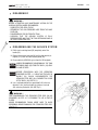
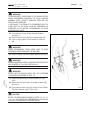
D I S A S S E M B LY
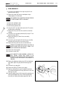
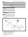
1. REMOVE THE RING (SMALLER DIAMETER) OF THE
RUBBER BOTTOM CASING (177) FROM ITS SEAT IN THE
1ST STAGE BODY (FIG. 1).
2. PULL THE RUBBER BOTTOM CASING (177) AWAY FROM
THE THREADED PINS OF THE PLASTIC TOP CASING
(178).
ꔼ
CAUTION
DURING THE OPERATIONS DESCRIBED IN STEP 2) DO NOT
BEND THE RUBBER BOTTOM CASING EXCESSIVELY TO AVOID
DEFORMING OR BREAKING IT.
Fig. 1
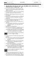
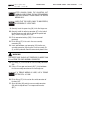
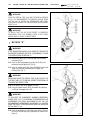
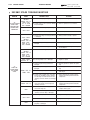
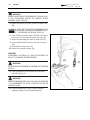
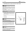
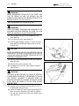
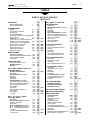
3. REMOVE THE RING (LARGER DIAMETER) OF THE
RUBBER LOWER CASING (177) FROM ITS SEAT IN THE
1ST STAGE BODY (FIG. 2) RELEASING THE PLASTIC TOP
CASING (178).
Fig. 2
BTM5 5-2
TECHNICAL BULLETIN
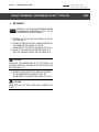
SUBJECT: ASSEMBLING - DISASSEMBLING THE V32 1ST STAGE CAP
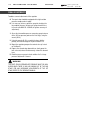
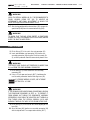
A S S E M B LY
NOTE
CARRY OUT THE FOLLOWING OPERATIONS BEFORE
THE PROCEDURE DESCRIBED IN STEP 1 OF THE
CORRESPONDING SERVICE MANUAL.
1. CORRECTLY FIT THE PLASTIC TOP CASING (178) ON THE
1ST STAGE BODY.
2. CORRECTLY POSITION THE RING (LARGER DIAMETER) OF
THE RUBBER BOTTOM CASING (177) ON THE
CONNECTORS OF THE PLASTIC TOP CASING (178) (Fig. 2).
3. MATCH UP THE SEATS ON THE BOTTOM CASING (177)
WITH THE THREADED PINS ON THE TOP CASING (178)
ꔼ
CAUTION
MAKE SURE THE THREADED PINS OF THE TOP CASING (178)
HAVE BEEN CORRECTLY INSERTED INTO THEIR SEATS ON THE
BOTTOM CASING (177).
4. CORRECTLY POSITION THE RING (SMALLER DIAMETER)
OF THE RUBBER BOTTOM CASING (177) ON THE
CONNECTORS OF THE PLASTIC TOP CASING (178) (Fig. 1).
ꔼ
CAUTION
MAKE SURE THAT THE FIRST STAGE CAP IS CORRECTLY IN
PLACE.
original copywriter 1987
revised 03.13.02 - printed 2002
BTM5
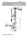
F 1-10
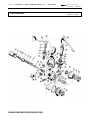
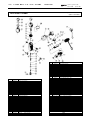
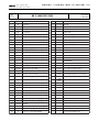
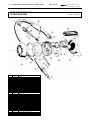
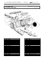
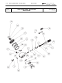
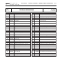
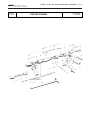
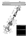
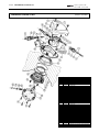
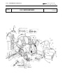
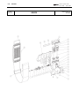
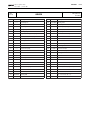
1 ST STAGE MR 22 - RUBY (TITANIUM) - ABYSS -V32
FIRST STAGE RUBY
DRAWING CONTINUED FROM PREVIOUS TABLE
REGULATORS
original copywriter 1987
revised 2001 - printed 2002
Reference drawing No.: E 3 - Table NO. 2
Updated to 03-04-2000
REGULATORS
original copywriter 1987
revised 2001 - printed 2002
Table
No. 2
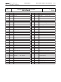
1 ST STAGE MR22 - RUBY (TITANIUM) - ABYSS - V32
Drawing reference No.: E 3
Table updated on
30/10/2001
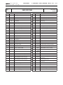
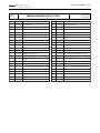
RUBY FIRST STAGE
Ref. N.
Code
1
A
2
Description
F 1-11
Ref. N.
Code
Description
1ST Stage Body with DFC por t
61
46185013
Filter spring
46185015
Snap ring Int. D. 13
62
46183013
DIN connector dust cap
3
46185211
Yoke
68
46183052
Pentagonal spring for DIN connector D. 12
4
D
HP chamber
69
46186218
Shock ring
5
46185038
Backup ring
71
46110413
OR 2050 Viton 014-9707
6
46110401
OR 2012 Viton 006-9707
74
46110403
OR 2031 Viton 011-9707
7
46186205
Yoke retainer nut
75
46186249
SCS poppet seat (RUBY)
8
46186306
RUBY poppet spring
76
46186210
HP chamber spring
ST
9
46186250
RUBY 1
79
F
12
46186214
Poppet pin
80
46186206
Anti-drag head
13
46186213
Poppet button
81
46186208
Plug
14
46185022
Diaphragm
89
46184309
RUBY Sticker
15
46185034
Spring base plate
148
46184315
"EN 250 - 200 bar" Sticker
16
46185023
Diaphragm spring
149
46184316
"MARES" Sticker
17
46186219
Retaining nut
18
46185028
Spring adjusting nut
19
46110402
OR 106 Viton 610-9707
20
46185204
3/8" UNF Por t plug
A
46200104
Complete RUBY 1st Stage Assembly
22
46186202
Tapered sintered filter
D
46186259
HP Chamber assembly (4-5-6)
F
416800
200 NX
Stage Poppet
23
46110406
OR 115 Viton 614-9707
24
46185010
Dust cap
25
46184079
Yoke knob
48
F
200 BAR (DIN) connector body
48
F
300 BAR (DIN) connector body
DIN connector spacer bushing
ASSEMBLIES
200 BAR DIN connector assembly
(23-48-49-56-62-68-71-79)
F
416800
300 NX
300 BAR DIN connector assembly
(23-48-49-56-62-68-71-79)
I
416851
C.W.D. KIT
46185167
RUBY INT. 1st Stage (VITON O-Ring)
Ser vice Kit
(DIN) 300 BAR threaded locking ring
(2-5-6-19-22-52-71-74)
46185168
RUBY DIN 1st Stage (VITON O-Ring)
Ser vice Kit
49
F
(DIN) 200 BAR threaded locking ring
49
F
***
52
46110404
OR 108 Viton 611-9754
***
53
46185205
7/16" HP por t plug
56
46183053
DIN connector filter D. 9
57
I
58
46185301
C.W.D. Diaphragm
98
46186207
1/2 UNF Por t plug
59
I
C.W.D. Locking ring
97
46110415
OR 2043 V
(5-6-19-23-52-56-68-71-74)
C.W.D. body
ACCESSORIES
F 1-12
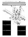
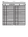
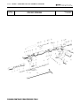
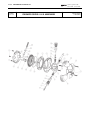
1 ST STAGE MR 22 - RUBY (TITANIUM) - ABYSS - V32
FIRST STAGE ABYSS
Ref.No.
1
2
3
4
5
6
6
7
8
9
12
13
14
15
16
17
18
19
19
20
22
23
23
24
25
48
48
49
49
52
52
53
56
57
58
59
61
62
68
69
71
71
74
74
Code
46186203
46185015
46185211
46185209
46185038
46110101
46110401
46186205
46185011
46185002
46186214
46186213
46185022
46185034
46185023
46186219
46185028
46110106
46110402
46185204
46186202
46110117
46110406
46185010
46184079
46183050
46183049
46183006
46183001
46110108
46110404
46185205
46183053
46185300
46185301
46185302
46185013
46183013
46183052
46186218
46110211
46110413
46110107
46110403
Description
1st stage body, DFC
Retaining ring D. int. 13
Yoke
HP housing
Back up ring
OR 2012
OR 2012
Viton 006-9707
Nut, yoke retainer
Spring poppet
Poppet, 1st stage
Pin, poppet
Button, poppet
Diaphragm
Plate, spring base
Spring, diaphragm
Retaining ring
Regulating nut, spring
OR 106
OR 106
Viton 610-9707
Plug, 3/8" UNF
Conical sintered filter
OR 115
OR 115
Viton 614-9707
Dust cap
Knob assembly
DIN connector body 200 BAR
DIN connector body 300 BAR
DIN connector wheel 200 BAR
DIN connector wheel 300 BAR
OR 108
OR 108
Viton 611-9754
Plug, HP 7/16"
Filter, DIN connector D. 9
Body, CWD
Diaphragm, CWD
Bezel, CWD
Spring, filter
Dust cap, DIN connector
Spring, DIN connector D. 12
Shockproof ring
OR 2050
OR 2050
Viton 014-9707
OR 2031
OR 2031
Viton 011-9707
REGULATORS
original copywriter 1987
revised 2000 - printed 2001
Reference drawing No.: E 2 - Table NO. 5
Updated to 03-04-2000
Ref.No.
75
76
79
80
81
89
148
149
Code
46186216
46186210
46183051
46186206
46186208
46184324
46184315
46184316
A
A
A
A
D
F
46200106
46200107
46185988
46200108
46185210
416802 200
F
416802 300
I
***
416850
46186152
***
46186151
46186207
46110215
Description
1st stage poppet seat
Spring, HP housing
Spacer ring, DIN connector
Anti-trail head
1st stage plug
Label ABYSS
Label "EN 250 - 200 bar"
Label "MARES"
ASSEMBLIES
1st stage assembly ABYSS 2000
1st stage assembly ABYSS J
1st stage assembly ABYSS DIN
1st stage assembly ABYSS CWD
HP housing assy (4-5-6)
DIN connector assy 200 BAR
(23-48-49-56-62-68-71-79)
DIN connector assy DIN 300 BAR
(23-48-49-56-62-68-71-79)
CWD kit ABYSS
Maintenance kit, 1st stage ABYSS INT
(2-5-6-19-22-52-71-74)
Maintenance kit ABYSS DIN
(5-6-19-23-52-56-68-71-74)
ACCESSORIES
Plug, 1/2” UNF
OR 2043
REGULATORS
original copywriter 1987
revised 2001 - printed 2002
Table
No.19
1 ST STAGE MR22 - RUBY (TITANIUM) - ABYSS - V32
Drawing reference No.: E 2
table updated on
30/10/2001
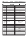
ABYSS FIRST STAGE
Ref. N.
Code
1
A
2
Description
F 1-13
Ref. N.
Code
1ST Stage body with DFC por t
68
46183052
Pentagonal spring for DIN connector D. 12
46185015
Snap ring Int. D. 13
69
46186218
Shock ring
3
46185211
Yoke
71
46110211
OR 2050
4
D
HP chamber
71
46110413
OR 2050 Viton 014-9707
5
46185038
Backup ring
74
46110107
OR 2031
6
46110101
OR 2012
74
46110403
OR 2031 Viton 011-9707
6
46110401
OR 2012 Viton 006-9707
75
46186216
1st Stage poppet seat
7
46186205
Yoke retainer nut
76
46186210
8
46185011
Poppet spring
79
F
9
46200276
1ST Stage poppet
80
46186206
Anti-drag head
12
46186214
Poppet pin
81
46186208
1ST Stage por t plug
13
46186213
Poppet button
89
46184324
ABYSS Sticker
14
46185022
Diaphragm
148
46184315
"EN 250 - 200 bar" Sticker
15
46185034
Spring base plate
149
46184316
"MARES" Sticker
16
46185023
Diaphragm spring
17
46186219
Retaining nut
18
46185028
Spring adjusting nut
19
46110106
OR 106
A
19
46110402
OR 106 Viton 610-9707
A
20
46185204
3/8" UNF Por t plug
D
46185210
F
416800 200
NX
F
416800 300
NX
22
46186202
Tapered sintered filter
23
46110117
OR 115
Description
HP chamber spring
DIN connector spacer bushing
ASSEMBLIES
46200106
Complete ABYSS 1st Stage assembly
< 46185988 > Complete ABYSS DIN 1st Stage Assembly
HP Chamber assembly. (4-5-6)
200 BAR DIN connector assembly
(23-48-49-56-62-68-71-79)
300 BAR DIN connector assembly
23
46110406
OR 115 Viton 614-9707
24
46185010
Dust cap
25
46184079
Yoke knob
48
F
48
F
300 BAR DIN connector body
49
F
DIN 200 BAR threaded locking ring
49
F
DIN 300 BAR threaded locking ring
52
46110108
OR 108
52
46110404
OR 108 Viton 611-9754
53
46185205
7/16" HP por t plug
56
46183053
DIN connector filter D. 9
57
I
58
46185301
C.W.D. Diaphragm
59
I
C.W.D. Locking ring
61
46185013
Filter spring
98
46186207
1/2 UNF Por t plug
62
46183013
DIN connector dust cap
97
46110215
OR 2043
200 BAR DIN connector body
(23-48-49-56-62-68-71-79)
I
416851
***
46186152
***
46186151
C.W.D. KIT
ABYSS INT. 1ST Stage Ser vice Kit
(2-5-6-19-22-52-71-74)
ABYSS DIN Ser vice Kit
(5-6-19-23-52-56-68-71-74)
***
46185167
ABYSS INT. NITROX 1ST Stage Ser vice Kit.
(VITON O-Ring)
(2-5-6-19-22-52-71-74)
***
46185168
ABYSS NITROX DIN 1ST Stage Ser vice Kit
(VITON O-Ring)
(5-6-19-23-52-56-68-71-74)
C.W.D. body
ACCESSORIES
F 1-14
Drawing
No E 12
1 ST STAGE MR22 - RUBY (TITANIUM) - ABYSS - V32
V 32 FIRST STAGE
REGULATORS
original copywriter 1987
revised 2001 - printed 2002
Drawing updated on
al 05/12/2001
REGULATORS
original copywriter 1987
revised 2001 - printed 2002
Table
No 21
1 ST STAGE MR22 - RUBY (TITANIUM) - ABYSS - V32
Drawing reference No.: E 12
Table updated on
02/04/2002
V 32 FIRST STAGE
Ref. N.
Code
1
A
2
Description
F 1-15
Ref. N.
Code
V32 1st Stage Body with DFC por t
68
46183052
Pentagonal spring for DIN connector D. 12
Description
46185015
Snap ring Int. D. 13
71
46110211
OR 2050
3
46186270
Sandblasted yoke
71
46110413
OR 2050 Viton 014-9707
4
D
HP chamber
74
46110107
OR 2031
5
46185038
Backup ring
74
46110403
OR 2031 Viton 011-9707
6
46110101
OR 2012
76
46186210
HP chamber spring
6
46110401
OR 2012 Viton 006-9707
79
F
DIN connector spacer bushing
7
46186205
Yoke retainer nut
80
46186206
Anti-drag head
8
46186306
Poppet spring
81
46186208
1st Stage por t plug.
9
46200175
SCS 1st Stage poppet
114
H
SCS poppet seat
12
46186214
Poppet pin
115
H
Poppet seat retaining washer
13
46186213
Poppet button
116
46110405
OR 4 X 1
14
46185022
Diaphragm
148
46184315
" EN 250 " Yoke sticker
15
46185034
Spring base plate
176
46200351
Oval Sticker
16
46185023
Diaphragm spring
177
46200368
V32 bottom casing
17
46186268
Sandblasted retaining nut
178
46200367
V 32 top casing
18
46185028
Spring adjusting nut
19
46110106
OR 106
19
46110402
OR 106 Viton 610-9707
20
46185204
3/8" UNF Por t plug
A
46200405
V32 1st Stage assembly
22
46186202
Tapered sintered filter
D
46185210
HP Chamber assembly. (4-5-6)
23
46110117
OR 115
H
46186249
SCS poppet seat
23
46110406
OR 115 Viton 614-9707
***
46186152
INT 1st Stage 32/22/16/TP Ser vice Kit
24
46185010
Dust cap
25
46184079
Yoke knob
48
F
ASSEMBLIES
(2-5-6-19-22-52-71-74)
***
46186151
DIN 1st Stage 32/22/16/TP Ser vice Kit
200 BAR DIN connector body
(5-6-19-23-52-56-68-71-74)
DIN 200 BAR threaded locking ring
46185167
INT VITON 1st Stage Ruby/32/22/16
Ser vice Kit
49
F
***
52
46110108
OR 108
52
46110404
OR 108 Viton 611-9754
53
46185205
7/16" HP por t plug
56
46183053
DIN connector filter D. 9
57
I
58
46185301
C.W.D. Diaphragm
59
I
C.W.D. Locking ring
98
46186207
1/2 UNF Por t plug
61
46185013
Filter spring
97
46110215
OR 2043
62
46183013
DIN connector dust cap
(2-5-6-19-22-52-71-74)
***
46185168
DIN VITON 1st Stage Ruby/32/22/16
Ser vice Kit
(5-6-19-23-52-56-68-71-74)
C.W.D. body
ACCESSORIES
Table
No. 8
1 ST S TA GE M R 1 6 - V 1 6 - V X 1 6 - T I P L A N E T
REGULATORS
original copywriter 1987
revised 2001 - printed 2002
Drawing reference No.: E 6
Table updated
on 30/10/2001
FIRST STAGE V 16 2000 - V 16 2000 NITROX - VX 16
Ref. N.
Code
1
A
2
Description
Ref. N.
Code
Description
1st stage body DFC V 16
61
46185013
Filter spring
46185015
Snap ring Int. D. 13
62
46183013
DIN connector dust cap
3
46185211
V 16 yoke
68
46183052
Pentagonal spring for DIN connector D. 9
4
D
H.P. chamber
71
46110211
OR 2050
5
46185038
Backup ring
71
46110413
OR 2050
6
46110101
OR 2012
74
46110107
OR 2031
6
46110401
OR 2012
74
46110403
OR 2031
46186210
Viton 006-9707
Viton 014-9707
Viton 011-9707
7
46186241
Yoke retainer nut
76
8
46186306
V 16 Valve Spring
79
F
9
46186304
1ST stage valve Titanium V16
80
46186206
Anti-drag head
12
46186214
Poppet pin
81
46186208
Por t plug
13
46185032
Poppet button
108
46185266
C.W.D. dust cap
14
46185022
Diaphragm
109
46186239
V 16 SCS tampographic body protection
15
46185034
Spring base plate
110
46186245
Tampographic dust cap
16
46185023
Diaphragm spring
115
46186249
SCS poppet seat (V 16)
17
46186219
Retaining nut
148
46184315
"EN 250 - 200 bar" Sticker
18
46185028
Spring adjuster nut
149
46184316
"MARES" Sticker
19
46110106
OR 106
19
46110402
OR 106
20
46185204
3/8" UNF Por t plug
22
46186202
Tapered sintered filter
A
46200109
1st Stage assembly V 16
23
46110117
OR 115
D
46185210
H.P. chamber assembly ( 4-5-6 )
23
46110406
OR 115
D
46186259
Nitrox H.P. chamber assembly ( 4-5-6 )
F
416803
200 NX
F
416803
300 NX
24
46185010
V 16 dust cap
25
46184079
V 16 yoke nut
Viton 610-9707
Viton 614-9707
H.P. chamber spring
DIN connector spacer bushing
ASSEMBLIES
Connector Assembly DIN 200 BAR Nitrox
( 23-48-49-56-62-68-71-79 )
48
F
200 BAR DIN connector body
48
F
300 BAR DIN connector body
Connector Assembly DIN 300 BAR Nitrox
( 23-48-49-56-62-68-71-79 )
49
F
Blocking ring nut (DIN) 200 BAR
I
416851
49
F
Blocking ring nut (DIN) 300 BAR
***
46186152
52
46110108
OR 108
52
46110404
OR 108
53
46185205
H.P. 7/16" UNF por t plug
56
46183053
DIN connector filter D.9
57
I
58
46185301
59
I
AER KIT
Ser v.kit. INT 1° STD 32/22/16/TP
( 2-5-6-19-22-52-71-74 )
Viton 611-9707
***
46186151
C.W.D. diaphragm
Ser v.kit. DIN 1° STD 32/22/16/TP
( 5-6-19-23-52-56-68-71-74 )
***
46185167
C.W.D. body
C.W.D. ring nut
F 2-9
Ser v.kit. INT VITON 1st STG Ruby/32/22/16
( 2-5-6-19-22-23-52-56-68-71-74)
***
46185168
Ser v.kit. DIN VITON 1st STG Ruby/32/22/16
( 5-6-19-23-52-56-68-71-74)
F 2-10
1 ST S TA GE MR 16 - V 16 - VX 16 - TI PL A N E T
REGULATORS
original copywriter 1987
revised 2000 - printed 2001
Reference drawing No. : E 1 - Table No. 1
Update to: 03-04-2000
FIRST STAGE TI PLANET
Rif. N.
1
2
3
4
5
6
6
7
8
9
12
13
14
15
16
17
18
19
19
20
22
23
23
24
25
48
48
49
49
52
52
53
Codice
46186240
46185015
46185211
46185209
46185038
46110101
46110401
46186241
46186306
46186304
46186214
46185032
46185022
46185034
46185023
46186219
46185028
46110106
46110402
46185204
46186202
46110117
46110406
46185010
46184079
46183036
46183035
46183006
46183001
46110108
46110404
46185205
Descrizione
Corpo 1° st. DFC V 16
Seeger D. int. 13
Brida V 16
Camera H.P.
Anello antiestrusione
OR 2012
OR 2012
Viton 006-9707
Esagono Trattenuta brida
Molla Valvola V 16
Valvola 1° st. Titanio V16
Spillo valvola
Disco spinta
Membrana
Piattello appoggio molla
Molla premi membrana
Dado di bloccaggio
Dado regolazione molla
OR 106
OR 106
Viton 610-9707
Tappo chiusura 3/8" UNF
Filtro sinterizzato conico
OR 115
OR 115
Viton 614-9707
Tappo protezione V 16
Manopola tiraggio brida V 16
Corpo attacco (DIN) 200 BAR
Corpo attacco (DIN) 300 BAR
Ghiera di blocc. (DIN) 200 BAR
Ghiera di blocc. (DIN) 300 BAR
OR 108
OR 108
Viton 611-9707
Tappo chiusura H.P. 7/16" UNF
Rif. N.
56
57
58
59
61
62
68
71
71
74
74
75
76
79
80
81
108
109
110
148
149
Codice
46183053
46185300
46185301
46185302
46185013
46183013
46183052
46110211
46110413
46110107
46110403
46186249
46186210
46183034
46186206
46186208
46185266
46186239
46186245
46184315
46184316
A
A
A
D
D
F
46200109
46200110
46200111
46185210
46186259
416803 200 NR
F
F
F
I
***
***
***
***
Descrizione
Filtro x attacco DIN D.9
Corpo C.W.D.
Membrana C.W.D.
Ghiera C.W.D.
Molla premi filtro
Tappo protezione attacco DIN
Molla pentag. x attacco DIN D. 9
OR 2050
OR 2050
Viton 014-9707
OR 2031
OR 2031
Viton 011-9707
Sede valvola SCS (V 16)
Molla premi camera H.P.
Boccola distanziale attacco DIN
Testa antitrascinamento
Tappo chiusura
Calotta di protezione C.W.D.
Protezione corpo V 16 SCS tampografata
Calotta di protezione tampografata
Etichetta "EN 250 - 200 bar"
Etichetta "MARES"
COMPLETI
1° Stadio CPL. V 16 2000
1° Stadio CPL. V 16 2000 J
1° Stadio CPL. V 16 DIN 2000
Camera H.P. compl. (4-5-6)
Camera H.P. compl. (4-5-6) Nitrox
Attacco completo DIN 200 BAR
(23-48-49-56-62-68-71-79)
416803 300 NR Attacco completo DIN 300 BAR
(23-48-49-56-62-68-71-79)
416803 200 NX Attacco Compl. DIN 200 BAR Nitrox
(23-48-49-56-62-68-71-79)
416803 300 NX Attacco Compl. DIN 300 BAR Nitrox
(23-48-49-56-62-68-71-79)
416851
KIT CWD V 16
46186152
Kit manutenzione 1° st. V 16 INT.
( 2-5-6-19-22-52-71-74 )
46186151
Kit manutenzione 1° st. V 16 - V 16 DIN
(5-6-19-23-52-56-68-71-74)
46185167
Kit manutenzione 1° st. V 16 INT. Viton
( 2-5-6-19-22-23-52-56-68-71-74)
46185168
Kit manut. 1° st. V 16 - V 16 DIN Viton
(5-6-19-23-52-56-68-71-74)
NOTE
Nel Kit (cod. 186151 e 186152) l'OR (74) della sede valvola è anche in Viton
Table
No. 1
1 ST S TA GE M R 1 6 - V 1 6 - V X 1 6 - T I P L A N E T
REGULATORS
original copywriter 1987
revised 2001 - printed 2002
Drawing reference No.: E 1
Table updated
on 30/10/2001
FIRST STAGE TI PLANET
Ref. N.
Code
1
A
2
Description
F 2-11
Ref. N.
Code
Ti Planet 1st stage body
59
I
Description
46185015
Snap ring INT.D. 3
61
46185013
Filter spring
3
46186500
Titanium 98 yoke
62
46183013
DIN connector dust cap
4
D
HP Chamber ( TI )
68
46183052
Pentagonal spring for DIN connector D. 9
5
46185038
Backup ring
71
46110211
OR 2050
6
46110101
OR 2012
74
46110107
OR 2031
7
46186504
Yoke retainer nut
76
46186210
H.P. chamber spring
8
46186306
Poppet spring
79
F
C.W.D. ring nut
DIN connector spacer bushing
9
46186304
Titanium 1st Stage poppet
80
46186206
Anti-drag head
12
46186505
Poppet pin
81
46186515
Por t plug
13
46186506
Poppet button
115
46186559
Titanium 1st stage poppet seat
14
46185022
Diaphragm
148
46184315
"EN 250 - 200 bar" Sticker
15
46185034
Spring base plate
149
46184316
"MARES" Sticker
16
46185023
Diaphragm spring
153
46110176
OR 3118
17
46186507
Retaining nut
154
46187016
Plastic saddle
18
46186508
Spring adjuster nut
157
46186529
Protection ring
19
46110106
OR 106
20
46186509
3/8" UNF Por t plug
22
46186202
Tapered sintered filter
23
46110117
OR 115
A
46200100
1st Stage assembly TI PLANET
24
46185010
Dust cap
D
46186556
H.P. chamber assembly ( 4-5-6 )
25
46186528
yoke nut ( TI )
F
46200103
300 BAR DIN connector assembly
48
F
300 BAR DIN connector body (TI )
49
F
Blocking ring nut (DIN) 300 BAR ( TI )
52
46110108
OR 108
53
46186512
7/16" HP por t plug UNF ( TI )
56
46183053
DIN connector filter D.9
57
I
58
46185301
C.W.D. body
C.W.D. diaphragm
ASSEMBLIES
( 23-48-49-56-62-68-71-79 )
I
416854
***
46186152
***
46186151
KIT CWD TI PLANET
Ser v.kit. INT 1° STD 32/22/16/TP
( 2-5-6-19-22-52-71-74 )
Ser v.kit. DIN 1° STD 32/22/16/TP
( 5-6-19-23-52-56-68-71-74 )
MR12 - MRX12 V12 - MR12 LONG
FIRST STAGE
MR12 - MRX12 - V12 MR12 LONG FIRST STAGE
F 3-8
1 ST STAGE MR12 - MRX12 - V12 - MR12 LONG
FIRST STAGE MR12 DFC 2000
FIRST STAGE MR12 NITROX
FIRST STAGE MRX12 DFC
DRAWING CONTINUED FROM PREVIOUS TABLE
REGULATORS
original copywriter 1987
revised 2000 - printed 2001
Reference drawing No. : E8 - Table No. 12-13
Updated to 03-04-2000
Code
Ref.N.
Code
MR 12 DFC Body
58
46185301
C.W.D. Diaphragm
46185015
Snap ring INT.D. 13
59
I
C.W.D. Locking ring
3
46185211
MR 12 yoke
62
46183013
DIN connector dust cap
4
D
H.P. chamber
70
46184452
MR 12 cap
5
46185038
Backup ring
148
46184315
"EN 250 - 200 bar" Sticker
6
46110101
OR 2012
149
46184316
"MARES" Sticker
6
46110401
OR 2012
7
46185212
Yoke retainer nut
1
A
2
Description
Description
Viton 006-9707
ASSEMBLIES
8
46185011
MR 12 valve spring
9
46185002
MR 12 first stage valve
A
46186286
1st Stage assembly MR 12
12
46185206
MR 12 valve core
D
46185210
H.P. chamber assembly ( 4-5-6 )
13
46185032
Poppet button
D
46186259
Nitrox H.P. chamber assembly ( 4-5-6 )
F
416804
200 NX
F
416804
300 NX
14
46185022
Diaphragm
15
46185034
Spring base plate
16
46185023
Diaphragm spring
17
46184510
Retaining nut
18
46184511
Spring adjustment nut
18
46185028
Spring adjustment nut (C.W.D.)
19
46110106
OR 106
Nitrox 200 BAR DIN connector assembly
( 23-48-49-50-51-62 )
Nitrox 300 BAR DIN connector assembly
( 23-48-49-50-51-62 )
I
416851
***
46186150
CWD Kit
Ser v.kit. INT/DIN 1st STG 12/LONG
( 2-5-6-19-22-23-50-52-74 )
19
46110402
OR 106
20
46185204
3/8" UNF Por t plug
22
46185014
Sintered filter
23
46110117
OR 115
23
46110406
OR 115
24
46185010
MR 12 protection cap
----
415861
25
46184079
MR12 yoke nut
---
46179258
48
F
Connector body (DIN) 200 BAR
---
48
F
Connector body (DIN) 300 BAR
49
F
DIN 200 BAR threaded locking ring
49
F
DIN 300 BAR threaded locking ring
50
46110203
OR 2018
Viton 610-9707
***
46186154
50
46110409
OR 2018
51
F
51
F
52
Ser v.kit. INT/DIN VITON 1st STG 12/LONG
( 2-5-6-19-22-23-50-52-74 )
ACCESSORIES
Viton 614-9707
INT/DIN yoke connector assembly (200 BAR)
INT/DIN nut connector assembly
Por t plug external DIN thread
SAFE FIRST ACCESSORIES
----
46200180
Extra 1st stage hose (Safe first)
----
46200241
1st stage cap Yellow
Connector coupling (DIN) 200 BAR
----
46200177
Swivel connector fixed par t
Connector coupling (DIN) 300 BAR
----
46110215
OR 2043
46110108
OR 108
----
46110205
OR 105
52
46110404
OR 108
----
46200178
Swivel connector mobile par t
53
46185205
----
46200176
Swivel connector cap
57
I
Viton 008-9707
Viton 611-9707
7/16" HP por t plug
C.W.D. body
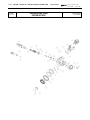
F 3-9
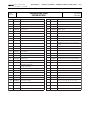
Drawing reference No: E 8
Table updated
on 30/10/2001
MR 12 DFC FIRST STAGE
MR 12 NITROX
Table
No. 12
Ref.N.
1 ST STAGE MR12 - MRX12 - V12 - MR12 LONG
REGULATORS
original copywriter 1987
revised 2001 - printed 2002
F 3-10
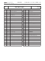
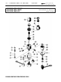
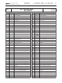
1 ST STAGE MR12 - MRX12 - V12 - MR12 LONG
Drawing
No. E 13
REGULATORS
MR 12 LONG FIRST STAGE
original copywriter 1987
revised 2001 - printed 2002
Drawing updated
on 21/12/2001
Table
No. 22
Ref.N.
1 ST STAGE MR12 - MRX12 - V12 - MR12 LONG
REGULATORS
original copywriter 1987
revised 2001 - printed 2002
Drawing reference No: E 13
Table updated
on 04/02/2002
MR 12 LONG FIRST STAGE
Code
Description
Ref.N.
Code
Description
1
A
V 12 Body
52
46110108
OR 108
2
46185015
Snap ring INT.D. 13
52
46110404
OR 108
3
46185211
MR 12 yoke
53
46185205
7/16" HP por t plug
4
D
H.P. chamber
57
I
5
46185038
Backup ring
58
46185301
C.W.D. Diaphragm
6
46110101
OR 2012
59
I
C.W.D. Locking ring
6
46110401
OR 2012
62
46183013
DIN connector dust cap
7
46185212
Yoke retainer nut
70
46200235
Proton 1st stage cap
Viton 006-9707
Viton 611-9707
C.W.D. body
8
46185011
MR12 valve spring
74
46110107
OR 2031
9
46200276
Pebax 1st Stage poppet
74
46110403
OR 2031
12
46186303
V 12 poppet pin
75
46186216
1st stage poppet seat
13
46185032
Poppet button
148
46184315
"EN 250 - 200 bar" Sticker
14
46185022
Diaphragm
149
46184316
"MARES" Sticker
15
46185034
Spring base plate
16
46185023
Diaphragm spring
17
46184510
Retaining nut
18
46184511
Spring adjuster nut
18
46185028
19
46110106
19
46110402
OR 106
20
46185204
3/8" UNF Por t plug
22
46185014
Sintered filter
23
46110117
OR 115
23
46110406
OR 115
24
46185010
MR 12 dust cap
25
46184079
MR12 yoke nut
48
F
Connector body (DIN) 200 BAR
48
F
Connector body (DIN) 300 BAR
49
F
DIN 200 BAR threaded locking ring
49
F
DIN 300 BAR threaded locking ring
50
46110203
OR 2018
50
46110409
OR 2018
51
F
51
F
Viton 011-9707
ASSEMBLIES
A
46200406
1st Stage assembly MR 12 Long
Spring adjuster nut (C.W.D.)
D
46185210
H.P. chamber assembly ( 4-5-6 )
OR 106
D
46186259
Nitrox H.P. chamber assembly ( 4-5-6 )
F
416804
200 NX
Nitrox 200 BAR DIN connector assembly
Viton 610-9707
F 3-11
( 23-48-49-50-51-62 )
F
416804
300 NX
Nitrox 300 BAR DIN connector assembly
( 23-48-49-50-51-62 )
Viton 614-9707
Viton 008-9707
I
416851
***
46186150
CWD Kit
Ser v.kit. INT/DIN 1st STD 12/LONG
( 2-5-6-19-22-23-50-52-74 )
***
46186154
Ser v.kit. INT/DIN VITON 1st STG 12/LONG
( 2-5-6-19-22-23-50-52-74 )
ACCESSORIES
----
415861
Connector coupling (DIN) 200 BAR
----
46179258
Connector coupling (DIN) 300 BAR
----
INT/DIN yoke connector assembly (200 BAR)
INT/DIN nut connector assembly
Por t plug external DIN thread
REGULATORS
original copywriter 1987
revised 2001 - printed 2002
F I RS T S TA G E R1 - R 2
Drawing reference No.: E 7
Table updated
on 30/10/2001
FIRST STAGE R2 DFC FIRST STAGE R2 NITROX
Table
No. 16
Ref. N.
Code
1
A
Description
Ref. N.
Code
Description
1st stage body
61
46185013
Filter spring
2
46185015
Snap ring D. 13
62
46183013
DIN connector dust cap
3
46185211
Yoke
82
46186221
Spring washer
7
46185212
Yoke retainer nut
84
46186228
Piston
8
46186220
Piston spring
85
46186225
Closing cap
19
46110106
OR 106
86
46110224
OR 2100
19
46110402
OR 106
86
46110419
OR 2100
20
46185204
3/8" UNF Por t plug
88
46186223
Piston seat
22
46185014
Sintered filter
89
46184354
1st stage label R2
23
46110117
OR 115
148
46184315
"EN 250 - 200 bar" Sticker
23
46110406
OR 115
149
46184316
"MARES" Sticker
24
46185010
Dust cap
25
46184079
Yoke knob
48
F
Connector body (DIN) 200 BAR
48
F
Connector body (DIN) 300 BAR
A
46200112
49
F
DIN 200 BAR threaded locking ring
F
416804
200 NX
49
F
DIN 300 BAR threaded locking ring
50
46110203
OR 2018
50
46110409
OR 2018
51
F
Connector coupling (DIN) 200 BAR
51
F
Connector coupling (DIN) 300 BAR
52
46110108
OR 108
52
46110404
OR 108
53
46185205
H.P. 7/16" UNF closing plug
Viton 610-9707
Viton 614-9707
F 6-7
Viton 022-9707
ASSEMBLIES
Nitrox 200 BAR DIN connector assembly
( 23-48-49-50-51-62 )
F
416804
300 NX
Viton 008-9707
Nitrox 300 BAR DIN connector assembly
( 23-48-49-50-51-62 )
***
46185323
INT/DIN 1st stage service kit
( 2-19-22-23-50-52-86-88 )
***
Viton 611-9707
CPL 1st Stage R2
46186155
Nitrox(VITON O-Ring) INT/DIN 1st stage
service kit
( 2-19-22-23-50-52-86-88 )
ADJUSTMENTS
original copywriter 1987
revised 2001 - printed 2002
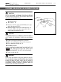
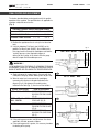
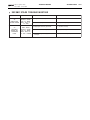
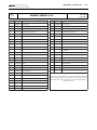
FIRST STAGES
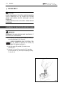
ADJUSTING AND CHECKING THE INTERMEDIATE PRESSURE
!
WARNING !
DO NOT SUBMERGE THE INTERMEDIATE PRESSURE MEASURING GAUGE.
Fig. 1
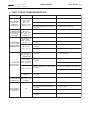
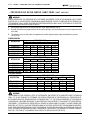
TABLE OF FIRST STAGE INTERMEDIATE PRESSURES
MODEL
P.S.I.
BAR
RUBY
142 - 148
9,8 - 10,2
V 32
142 - 148
9,8 - 10,2
MR 22
142 - 148
9,8 - 10,2
M R 16
142 - 148
9,8 - 10,2
TI PLANET
142 - 148
9,8 - 10,2
V 16
142 - 148
9,8 - 10,2
MR 12
142 - 148
9,8 - 10,2
V 12
142 - 148
9,8 - 10,2
MR 12 II°
137 - 142
9,5 - 9,8
R 2 (with tank at 2900 p.s.i./200 bar)
142 - 152
9,8 - 10,5
MR 10 (with tank at 2900 p.s.i. / 200 bar)
123 - 130
8,5 - 9,0
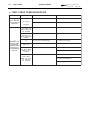
TABLE OF FIRST STAGE INTERMEDIATE PRESSURE WITH C.W.D. KIT
MODEL
P.S.I.
BAR
RUBY
130 - 136
9 - 9,4
V 32
130 - 136
9 - 9,4
MR 22
130 - 136
9 - 9,4
M R 16
130 - 136
9 - 9,4
TI PLANET
130 - 136
9 - 9,4
V 16
130 - 136
9 - 9,4
M R 12
130 - 136
9 - 9,4
V 12
130 - 136
9 - 9,4
MR 12 II°
130 - 136
9 - 9,4
F 7-1
F 7-2
FIRST STAGES
ADJUSTMENTS
original copywriter 1987
revised 2001 - printed 2002
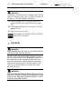
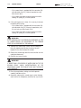
P R O C E D U R E F O R A D J U S T I N G T H E I N T E R M E D I AT E P R E S S U R E I N
D I A P H R A G M F I R S T S TA G E S
1. Screw the intermediate pressure measuring gauge (cod.
106252) into one of the 3/8" low pressure ports, using the
special wrench (B-18).
2. Using the wrench (B-18 or B-19), apply the hose with the
partially assembled second stage to the port marked D.F.C.
3. Mount the regulator group on the control valve (of a tank
or Test Bench).
(Only for MR 10 version)
It is important for the pressure (of the tank or Test Bench) to be
approximately 200 bar.
4. Holding down the second stage demand lever, slowly open
the tank valve and, almost simultaneously, release the
demand lever.
5. Read the value of the first stage adjustment on the pressure gauge, and proceed as follows (Fig. 1):
a. If the first stage pressure is greater than the required
value (see table), use the wrench (B-13) to slowly back
off the adjusting nut (16) until the required value is
obtained.
NOTE
WHENEVER THE INTERMEDIATE PRESSURE IS
REDUCED, IT IS NECESSARY TO VENT THE EXCESS AIR
IN ORDER TO OBTAIN A CORRECT READOUT OF THE
NEW VALUE.
b. If the first stage pressure is lower than the required
value (see table), slowly lock down the adjusting nut
until the specified value is obtained.
6. Operate the second stage demand lever a few times, and
check that the first stage pressure remains constant.
7. After completing the second stage adjustments, remove
the pressure gauge and screw on the corresponding port
plug.
original copywriter 1987
revised 2001 - printed 2002
ADJUSTMENTS
FIRST STAGES
P R O C E D U R E F O R A D J U S T I N G T H E I N T E R M E D I AT E P R E S S U R E I N
P I S T O N F I R S T S TA G E S ( R 1 - R 2 )
1. Screw the intermediate pressure measuring gauge (cod.
106252) into one of the 3/8" low pressure ports, using the
special wrench (B-18).
2. Using the wrench (B-18), apply the hose with the partially
assembled second stage to the port marked D.F.C.
3. Mount the regulator group on the control valve (of a tank
or Test Bench).
4. Holding down the second stage demand lever, slowly open
the tank valve and, almost simultaneously, release the
demand lever.
5. Read the value of the first stage adjustment on the pressure gauge, and proceed as follows (Fig. 1):
A. If the pressure setting is greater than the required value
(see table):
A. 1. Disassemble the regulator from the tank and proceed
as described in points 1 and 2 of the disassembly
operations.
A. 2. Remove one distance washer.
A. 3. Reassemble the components as described in steps 8.1
- 9 - 10 - 11 - 12 of the reassembly instructions.
A. 4. Proceed as described in steps 3 and 4 of the procedure
for checking the intermediate pressure, reading out the
value of the intermediate pressure on the gauge.
NOTE
If there are no distance washers in the First Stage, it
is necessary to replace the spring.
B. If the first stage pressure is lower than the required value
(see table):
B. 1. Disassemble the regulator from the tank and proceed
as described in points 1 and 2 of the disassembly
operations.
B. 2. Add one distance washer (up to a maximum of two)
positioning it/them as described in step 8 of the
reassembly operations.
B. 3. Reassemble the components as described in steps
9 - 10 - 11 - 12 of the reassembly instructions.
B.4. Proceed as described in steps 3 and 4 of the procedure
for checking the intermediate pressure, reading out the
value of the intermediate pressure on the gauge.
NOTE
If there are no distance washers in the First Stage, it is
necessary to replace the spring.
6. Operate the second stage demand lever a few times, and
check that the first stage adjustment remains constant.
7. After completing the second stage adjustments, remove the
pressure gauge and screw on the corresponding port plug.
F 7-3
original copywriter 1987
revised 2001 - printed 2002
F I R S T S TA G E S
TROUBLESHOOTING
F 8-1
F I R S T S TA G E T R O U B L E S H O O T I N G
PROBLEM
-1AIR LEAK FROM
FIRST STAGE
DIAPHRAGM
RETAINING NUT
MODEL
RUBY - MR22
MR16 - V16
MR12 - V12
MR12 II° - MR10
TI PLANET - V32
RUBY - MR22 -2MR16 - V16 AIR LEAK FROM THE
FIRST STAGE PORT MR12 - V12 - MR12
II° - MR10 - R2 PLUGS AND/OR
TI PLANET - V32
HOSE PORTS
-3AIR LEAK BETWEEN
THE FIRST STAGE
BODY AND THE INT
OR DIN CONNECTOR
INT - DIN Version of
RUBY - MR22 MR16 - V16 MR10 TI PLANET - V32
DIN version of
MR12 - V12 - R2
RUBY - MR22 - MR16
V16 - MR12 - V12
MR12 II° - MR10 - R2
TI PLANET - V32
-4AIR LEAK BETWEEN
FIRST STAGE INLET
AND TANK VALVE
RUBY - MR22
MR16 - V16 - MR10
V32 - TI PLANET
PROBABLE CAUSE
1) Lock down the nut
2) First stage diaphragm damaged
1) Replace the diaphragm
3) First stage diaphragm seating surface
damaged
1) Replace the first stage body
1) O-Ring dirty or damaged
1) Clean the seat and replace the O-Ring
2) Hose and/or port plug loose
1) Lock down
1) O-Ring seal dirty or damaged
1) Clean the seat and replace the O-Ring
2) INT yoke fitting or DIN connector body
loose
1) Lock down
3) DIN connector O-Ring seal dirty or
damaged
1) Clean the seat and replace the O-Ring
4) DIN connector body loose
1) Lock down
1) O-Ring seal of tank valve dirty or
damaged
1) Clean the seat of the tank valve and
replace the O-Ring
2) O-Ring sealing surface on the first stage
damaged
1) (INT version) Replace the yoke retainer
nut
2) (DIN version) replace the connector body
3) O-Ring sealing surface on the first stage
damaged
MR12 - V12 - R2
MR12 II°
-5AIR LEAK FROM THE
HP CHAMBER PLUG
-6AIR LEAK FROM
HOLES IN THE FIRST
STAGE CAP
RUBY - MR22 MR16 - V16 - V32 TI PLANET
R2
SOLUTION
1) Retaining nut loose
1) (INT version) Replace the first stage body
2) (DIN version) replace the connector coupling
4) O-Ring sealing surface on the first stage
damaged
1) Replace the first stage body
1) O-Ring defective
1) Replace
1) Piston O-Rings defective
1) Replace the O-Rings
2) Piston O-Ring sealing surfaces dirty or
damaged
1) Clean or replace
3) Inner surface of cap dirty or damaged
1) Clean or replace the cap
4) Inner surface of first stage dirty or
damaged
1) Clean or replace the first stage body
F 8-2
F I R S T S TA G E S
TROUBLESHOOTING
original copywriter 1987
revised 2001 - printed 2002
F I R S T S TA G E T R O U B L E S H O O T I N G
PROBLEM
-7(C.W.D. VERSION)
OIL LEAK FROM THE
DIAPHRAGM
-8CONTINUOUS AIR
DELIVERY FROM
SECOND STAGE
CHARACTERIZED BY
AN INCREASE IN
THE INTERMEDIATE
PRESSURE
MODEL
PROBABLE CAUSE
SOLUTION
RUBY - MR22
1) C.W.D. diaphragm damaged
1) Replace the A.E.R. diaphragm
V12 - MR12 II°
2) C.W.D. diaphragm retaining ring loose
1) Lock down correctly
RUBY - MR22 - MR16
- V16 - MR12 - V12
MR12 II° - MR10 - R2
V32 - TI PLANET
1) Intermediate pressure too high
1) Adjust the intermediate pressure
RUBY - MR22 - MR16
V16 - MR12 - V12
MR12 II° - MR10 - V32
TI PLANET
2) First stage poppet damaged
1) Replace
3) Piston friction lining damaged
1) Replace friction lining
4) Seat connector in first stage defective
1) Clean or replace first stage body
5) Seat connector defective
1) Clean or replace the seat
TI PLANET
R2
MR12 - R2
RUBY - MR22 -MR16
V16 - MR12 - MR10
MR12 II° - V32
TI PLANET
2) Replace the O-Ring
6) Defective HP chamber
RUBY - MR22
MR16 - V16 - MR12
V12 - MR12 II°
V32 - TI PLANET
1) Replace the O-Rings
2) Replace the backup ring
3) Clean or replace the HP chamber
S 1-8
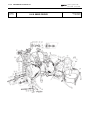
RUBY-ABYSS-VOLTREX-ORBITER SECOND STAGE
Table
No. 101
original copywriter 1987
revised 2001 - printed 2002
Drawing reference No.: E16
Table updated
on 30/10/2001
RUBY SECOND STAGE
Ref. N.
Code
19
46110415
21
REGULATORS
Description
OR 2043
Viton 013-9754
< 46186023 > Poppet seat
Ref. N.
Code
41
46186028
Exhaust tee 99
Description
41
46186310
Exhaust tee 2000
26
46184449
Black 1/2" super/flow hose
43
47157984
Mouthpiece clamp
27
46110411
OR 2025
44
46185086
Black mouthpiece
28
46184282
Case assembly connector
45
46179902
Black 1st stage hose protector
29
46110413
OR 2050
46
46186094
Black 2nd stage hose protector
30
46186024
Second stage poppet
47
46184062
Poppet seat
31
46185057
Poppet spring
Viton 010-9754
Viton
32
46186025
Second stage case
33
46185051
Demand lever nut
34
46185049
Washer
G
46186145
RUBY Second Stage Assembly
35
46185104
Demand Lever (C.W.D.)
G
46186146
RUBY J. Second Stage Assembly
36
46186029
Black diaphragm
39
46186256
RUBY cover assembly
37
46185073
Ring clamp
***
46185166
RUBY 2nd Stage Ser vice Kit
38
46185075
Ring clamp screw 3 x 16 stainless
ASSEMBLIES
( 19-27-29-33-40-43-47)
Viton
REGULATORS
original copywriter 1987
revised 2001 - printed 2002
Table
No. 103
RUBY-ABYSS-VOLTREX-ORBITER SECOND STAGE
Drawing reference No.: E16
Table updated
on 30/10/2001
ORBITER SECOND STAGE
Ref. N.
Code
Description
Ref. N.
19
46110106
OR 106 (VOLTREX)
19
46110402
OR 106
21
<46186023>
26
40
Viton 610-9754
41
Code
46184006
Description
Exhaust valve
< 46186028 > Exhaust tee 99
Seat connector
41
46186310
Exhaust tee 2000
46184450
Black super/flow hose
43
47157984
Mouthpiece clamp
27
46110205
OR 2025
44
46185086
Black mouthpiece
27
46110411
OR 2025
45
46179902
Black 1ST stage hose protector
28
46184282
Case assembly connector
46
46186094
Black 2ND stage hose protector
29
46110211
OR 2050
47
46184062
Poppet seat
29
46110413
OR 2050
30
46186024
Second stage poppet
Viton 010-9754
Viton
ASSEMBLIES
31
46185057
Poppet spring
32
46186025
2ND stage case
G
46186149
ORBITER Second Stage Assembly
33
46185051
Demand lever nut
39
46184279
ORBITER cover assembly
34
46185049
Washer
***
46186160
ORBITER 2nd Stage Ser vice Kit
35
46185104
Demand Lever (CWD)
36
46186029
Black diaphragm
37
46185073
Ring clamp
38
46185075
Ring clamp screw 3 x 16 stainless
( 19-27-29-33-40-43-47)
***
S 1-9
46185166
ORBITOR Nitrox 2ND Stage Ser vice Kit
(VITON O-Ring)
( 19-27-29-33-40-43-47)
S 1-10
RUBY-ABYSS-VOLTREX-ORBITER SECOND STAGE
ABYSS 2000 SECOND STAGE
OCTOPUS ABYSS 2000
N. Rif.
19
19
21
26
26
27
27
28
29
29
30
31
32
33
34
35
36
37
38
39
39
40
41
43
44
45
46
47
54
Codice
46110215
46110415
46186023
46184449
46186093
46110205
46110411
46184282
46110191
46110408
46186024
46185057
46186025
46185051
46185049
46185104
46186029
46185073
46185075
46186043
46186049
46184006
46186310
47157984
46185086
46179904
46186094
46184062
46186090
Descrizione
OR 2043
OR 2043
Viton 013-9754
Sede valvola
Manichetta 1/2" Abyss super/flow nera
Manichetta Octopus super/flow gialla
OR 2025
OR 2025
Viton 010-9754
Raccordo bocchettone manichetta
OR Parker 3-906
OR Parker 3-906
Viton 906-9754
Valvola chiusura
Molla valvola
Scatola 2° stadio
Dado fissaggio leva
Rondella
Leva erogazione (CWD)
Membrana nera
Fascetta di chiusura
Vite fascetta 3 x 16 inox
Coperchio cpl. Octopus ABYSS TF
Coperchio cpl. Nero ABYSS TF
Valvola scarico
Condotto scarico
Fascetta boccaglio
Boccaglio nero
Protezione manichetta nera 1° st.
Coprimanichetta nera 2° st.
Pasticca valvola
Tappo bocc. Octopus
G
G
***
46200121
46200122
46186160
Secondo Stadio cpl. ABYSS 2000
Secondo Stadio cpl. ABYSS 2000 J
Kit Manutenzione 2° st. ABYSS
(19-27-29-33-40-43-47)
COMPLETI
REGULATORS
original copywriter 1987
revised 2000 - printed 2001
Reference drawing No.:E 19 - Table No. 104
Updated to 03-04-2000
REGULATORS
original copywriter 1987
revised 2001 - printed 2002
Ref.N.
Code
19
46110215
Description
OR 2043
19
46110415
OR 2043
Viton 013-9754
< 46186023 > Seat connector
Ref.N.
Code
40
46184006
Exhaust valve
Description
41
46186310
Exhaust tee
43
47157984
Mouthpiece clamp
26
46184449
Black 1/2" Abyss super/flow hose
44
46185086
Black mouthpiece
26
46186093
Yellow octopus super/flow hose
45
46179902
Black 1st stage hose protector
27
46110205
OR 2025
46
46186094
Black 2nd Stage hose protector
27
46110411
OR 2025
47
46184062
Poppet seat
28
46184282
Case assembly connector
54
46186090
Octopus mouthpiece plug
Viton 010-9754
29
46110211
OR 2050
29
46110413
OR 2050
30
46186024
Second stage poppet
31
46185057
Poppet spring
G
46200121
ABYSS Second Stage assembly
32
46186025
2ND stage case
39
46186043
ABYSS TF octopus cover assembly
33
46185051
Demand lever nut
39
46186049
Black ABYSS TF cover assembly
34
46185049
Washer
***
46186160
ABYSS 2ND Stage Ser vice Kit
35
46185104
Demand lever (CWD)
36
46186029
Black diaphragm
37
46185073
Ring clamp
38
46185075
Ring clamp screw 3 x 16 stainless
Viton
ASSEMBLIES
( 19-27-29-33-40-43-47)
***
S 1-11
Drawing reference No.: E19
Table updated
al 30/10/2001
ABYSS T.F. SECOND STAGE
OCTOPUS ABYSS
Table
No. 104
21
RUBY-ABYSS-VOLTREX-ORBITER SECOND STAGE
46185166
ABYSS Nitrox 2nd Stage Ser vice Kit
(VITON O-Ring)
( 19-27-29-33-40-43-47)
original copywriter 1987
revised 2001 - printed 2002
REGULATORS
XTR-XL-AKROS-TI PLANET-EPOS SECOND STAGE
Drawing reference No.: E18
Table updated
on 03/04/2000
AKROS - OCTOPUS AKROS
AKROS NITROX SECOND STAGE
Table
No. 111
Description
Ref.N.
Code
Ref.N.
Code
19
46110106
OR 106
66
46110417
OR 2062 Viton 016-9707
19
46110402
OR 106 Viton 610-97507
71
46110211
OR 2050
21
46186023
Seat connector
71
46110413
OR 2050 Viton 014-9707
26
46186174
Black hi/flow hose
72
46110215
OR 2043
26
46186178
Yellow octopus hi/flow hose
72
46110415
OR 2043 Viton 013-9707
27
46110205
OR 2025
74
46184288
By pass Akros
27
46110411
OR 2025 Viton 010-9707
75
46200154
OR 7 X 2
28
46184282
Case assembly connector
75
46200299
OR 7 X 2 Viton
30
46184219
Valve stem
78
46184224
Diaphragm retaining ring
Description
31
46185057
Plug poppet spring
83
46110225
OR 2068
32
46184239
Black Akros case
83
46110420
OR 2068 Viton 017-9707
33
46185051
Demand lever nut
87
46184233
Adjuster access connector
34
46185049
Washer
90
46184223
Akros spacing ring
35
46185104
Demand lever CWD
91
46184281
Akros lever por t connector
36
46184225
Modular diaphragm
92
46184221
2nd stage poppet body. Akros
39
46184274
Cpl. black Akros cover
95
46184236
Akros deflector pin
39
46184276
Cpl. yellow Akros octopus cover
96
46184280
Bypass retainer ring
39
46184278
Cpl. Akros Nitrox cover
40
46184006
Exhaust valve
41
46184438
Exhaust tee
42
46184235
Mobile deflector
G
46184298
Second stage assembly. Akros Black
43
47157984
Mouthpiece clamp
G
46184299
Second stage assembly. Akros Black J.
44
46185086
Black mouthpiece
G
46184295
Second stage assembly. Akros Nitrox
45
46179902
Black 1st stage hose protector
G
46184302
Second stage assembly. Akros Nitrox J.
46
46184210
2nd stage hose protector
***
46200152
AKROS P.F. 2nd stage case
47
46184062
Poppet seat
54
46186090
Octopus mouthpiece plug
63
46184289
Cover lock pin
64
46184234
Adjuster por t plug
66
46110220
OR 2062
ASSEMBLIES
(32-42-95)
***
46186165
2nd Stage ser vice kit Akros
( 19-27-33-40-43-47-66-71-72-75-83 )
***
S 2-11
46186169
Ser vice kit 2nd stage Akros Nitrox
( 19-27-33-40-43-47-66-71-72-75-83 )
S 2-12
XTR-XL-AKROS-TI PLANET-EPOS SECOND STAGE
Table
No. 109
REGULATORS
original copywriter 1987
revised 2001 - printed 2002
Drawing reference No.: E18
Table updated
on 30/10/2001
XTR - XTR NITROX SECOND STAGE
Ref.N.
Code
Ref.N.
Code
19
46110106
OR 106
72
46110215
OR 2043
19
46110402
OR 106 Viton 610-97507
72
46110415
OR 2043 Viton 013-9707
74
46184288
By pass
21
Description
< 46186023 > Seat connector
Description
26
46186174
Black hi/flow hose
75
46200154
OR 7 X 2
27
46110205
OR 2025
75
46200299
OR 7 X 2
27
46110411
OR 2025 Viton 010-9707
78
46184224
Diaphragm retainer ring
28
46184282
Case assembly connector
83
46110225
OR 2068
30
46184219
Valve stem
83
46110420
OR 2068 Viton 017-9707
31
46185057
Plug poppet spring
87
46184233
Adjuster access connector
Viton
32
---
Black XTR case
90
46184223
Spacing ring
33
46185051
Demand lever nut
91
46184281
Lever por t connector
34
46185049
Washer
92
46184221
2nd stage poppet body
35
46185104
Demand lever CWD
95
46184236
Deflector pin
36
46184225
Modular diaphragm
96
46184280
Bypass retainer ring
40
46184006
Exhaust valve
41
<46184438>
42
46184235
Mobile deflector
43
47157984
Mouthpiece clamp
G
<46184300>
Second stage assembly. XTR
44
46185086
Black mouthpiece
G
<46184303>
Second stage assembly. XTR Nitrox J.
---
46200152
Exhaust tee
ASSEMBLIES
45
46179902
Black 1st stage hose protector
46
46184210
2nd stage hose protector
AKROS P.F. 2nd stage case
47
46184062
Poppet seat
39
46184259
XTR assembly cover Black
63
46184289
Cover lock pin
39
46184264
XTR assembly cover Nitrox
64
46184234
Adjuster por t plug
***
46186165
2nd Stage ser vice kit -XTR
66
46110220
OR 2062
66
46110417
OR 2062 Viton 016-9707
71
46110211
OR 2050
71
46110413
OR 2050 Viton 014-9707
(32-42-95)
( 19-27-33-40-43-47-66-71-72-75-83)
***
46186169
Ser vice kit 2nd stage XTR Nitrox
( 19-27-33-40-43-47-66-71-72-75-83)
original copywriter 1987
revised 2001 - printed 2002
Table
No. 110
REGULATORS
XTR-XL-AKROS-TI PLANET-EPOS SECOND STAGE
Drawing reference No: E 18
Table updated
on 30/10/2001
XL - OCTOPUS XL SECOND STAGE
Ref.N.
Code
Ref.N.
Code
19
46110106
OR 106
66
46110417
OR 2062 Viton 016-9707
19
46110402
OR 106 Viton 610-97507
71
46110211
OR 2050
71
46110413
OR 2050 Viton 014-9707
21
Description
< 46186023 > Seat connector
Description
26
46186174
Black hi/flow hose (XL)
72
46110215
OR 2043
26
46186178
Yellow octopus hi/flow hose
72
46110415
OR 2043 Viton 013-9707
27
46110205
OR 2025
74
46184288
By pass
27
46110411
OR 2025 Viton 010-9707
75
46200254
OR 7 X 2
28
46184282
Case assembly connector
75
46200299
OR 7 X 2
30
46184219
Valve stem
78
46184224
Diaphragm retainer ring
Plug poppet spring
83
46110225
OR 2068
Black XL case
83
46110420
OR 2068 Viton 017-9707
Viton
31
46185057
32
---
33
46185051
Demand lever nut
87
46184233
Adjuster access connector
34
46185049
Washer
90
46184223
Spacing ring
35
46185104
Demand lever CWD
91
46184281
Lever por t connector
36
46184225
Modular diaphragm
92
46184221
39
46184247
XL assembly cover
95
46184236
Deflector pin
39
46184249
XL Octopus assembly cover
96
46184280
Bypass retainer ring
40
46184006
Exhaust valve
41
<46184438>
42
46184235
Exhaust tee
2nd stage poppet body
ASSEMBLIES
Mobile deflector
43
47157984
Mouthpiece clamp
G
<46184301>
Second stage assembly. XL
44
46185086
Black mouthpiece
G
<46184052>
Second stage assembly. XL J
45
46179902
Black 1st stage hose protector
---
46200152
46
46184210
2nd stage hose protector
47
46184062
Poppet seat
54
46186090
Octopus mouthpiece cap
63
46184289
Cover lock pin
64
46184234
Adjuster por t plug
66
46110220
OR 2062
AKROS P.F. 2nd stage case
(32-42-95)
***
46186165
2nd Stage ser vice kit XL
( 19-27-33-40-43-47-66-71-72-75-83 )
***
S 2-13
46186169
Ser vice kit 2nd stage XL Nitrox
( 19-27-33-40-43-47-66-71-72-75-83 )
S 2-14
XTR-XL-AKROS-TI PLANET-EPOS SECOND STAGE
REGULATORS
Table No. E 15
Updated to 03-04-2000
TI PLANET SECOND STAGE
Ref.No.
19
21
26
27
28
30
31
32
33
34
35
36
40
41
42
43
44
45
46
47
63
64
66
71
72
74
Code
46110106
46186517
46184450
46110205
46186518
46186519
46185057
46186524
46185051
46185049
46185104
46184225
46184006
46186266
46184235
47157984
46185086
46179902
46184210
46184062
46184289
46186267
46110220
46110211
46110215
46184288
Description
OR 106
Poppet seat, 2nd stage (TI)
Hose super/flow, black
OR 2025
Hose connector
Poppet stem
Spring, poppet
2nd stage case TI PLANET
Retaining nut, lever
Washer
Lever CWD
Modular diaphragm
Exhaust valve
Exhaust tee
Pivoting vane
Mouthpiece clamp
Mouthpiece, black
Hose protector, 1st stage, black
Hose protector, 2nd stage, black
Poppet seat
Safety catch, cap
Regulating plug
OR 2062
OR 2050
OR 2043
By pass
original copywriter 1987
revised 2000 - printed 2001
Ref.No.
75
78
83
87
90
91
92
95
96
102
103
104
Code
46110107
46184224
46110225
46184233
46184223
46186520
46184221
46184236
46184280
46186032
46186027
46186552
Description
OR 2031
Locking ring, diaphragm
OR 2068
Plug seat
Spacer ring
Poppet housing
Body, poppet 2nd stage
Pin, vane
Retaining ring, bypass
Spring, button
Button
Button, plate
ASSEMBLIES
G
G
***
46184296
46200116
46186555
***
46200153
***
46186165
Second stage assy TI PLANET
Second stage assy TI PLANET J
Cover assy TI PLANET
(101-102-103-104-121)
Second stage case TI PLANET P.F.
(32-42-95)
Second stage maintenance kit TI PLANET
(19-27-33-40-43-47-66-71-72-75-83)
For components 121 and 101, see cover assy code 46186555
For component 106, see 2nd stage case assy code 46186524
REGULATORS
original copywriter 1987
revised 2001 - printed 2002
Table
No. 100
Ref.N.
XTR-XL-AKROS-TI PLANET-EPOS SECOND STAGE
Drawing reference No.: E 15
Table updated
on 30/10/2001
TI PLANET SECOND STAGE
Code
Description
S 2-15
Ref.N.
Code
Description
OR 106
75
46200154
OR 7 X 2
2nd stage poppet seat (TI).
78
46184224
Diaphragm retainer ring
19
46110106
21
<46186517>
26
46184450
Black Super/Flow hose
83
46110225
OR 2068
27
46110205
OR 2025
87
46184233
Adjuster access connector
28
46186518
Case assembly connector
90
46184223
Spacing ring
30
46186519
Valve stem
91
46186520
Lever por t connector
31
46185057
Plug poppet spring
92
46184221
2nd stage poppet body
32
---
TI PLANET 2nd stage case
95
46184236
Deflector pin
33
46185051
Demand lever nut
96
46184280
Bypass retainer ring
34
46185049
Washer
102
+++
Push-button spring
35
46185104
Demand lever CWD
103
+++
Push-button
36
46184225
Modular diaphragm
104
46186522
40
46184006
Exhaust valve
41
46186266
Exhaust tee
42
46184235
Mobile deflector
43
47157984
Mouthpiece clamp
G
416890
44
46185086
Black mouthpiece
+++
46186555
45
46179902
Black 1st stage hose protector
46
46184210
2nd stage hose protector
47
46184062
Poppet seat
63
46184289
Cover lock pin
64
46186267
Adjuster por t plug
66
46110220
OR 2062
71
46110211
OR 2050
72
46110215
OR 2043
74
46184288
By pass
Push-button disc
ASSEMBLIES
Second stage assembly. TI PLANET
Assembly cover TI PLANET
(101-102-103-104-121)
---
46200153
***
46186165
TI PLANET P.F. 2nd St case
(32-42-95)
2nd Stage ser vice kit TI PLANET
( 19-27-33-40-43-47-66-71-72-75-83 )
NOTES
For par ts 121 and 101 see assembly cover cod. 46186555
For par t 106 see second stage assembly case cod. 46186524
S 2-16
XTR-XL-AKROS-TI PLANET-EPOS SECOND STAGE
REGULATORS
EPOS SECOND STAGE
EPOS NITROX SECOND STAGE
Ref.No.
19
19
21
26
27
27
28
30
31
32
33
34
35
36
40
41
42
43
44
45
46
47
63
64
66
66
71
71
72
72
74
Code
46110106
46110402
46186023
46186174
46110205
46110411
46184282
46184219
46185057
46184230
46185051
46185049
46185104
46184225
46184006
46186266
46184235
47157984
46185086
46179902
46184210
46184062
46184289
46186267
46110220
46110417
46110211
46110413
46110215
46110415
46184207
Description
OR 106
OR 106
Viton 610-97507
Poppet seat
Hose hi-flow, black
OR 2025
OR 2025
Viton 010-9707
Hose connector
Poppet stem
Spring, poppet
2nd stage case Epos
Retaining nut, lever
Washer
Lever CWD
Modular diaphragm
Exhaust valve
Exhaust tee
Pivoting vane
Mouthpiece clamp
Mouthpiece, black
Hose protector, 1st stage, black
Hose protector, 2nd stage
Poppet seat
Safety catch, cover
Regulating plug
OR 2062
OR 2062
Viton 016-9707
OR 2050
OR 2050
Viton 014-9707
OR 2043
OR 2043
Viton 013-9707
By pass, grey, varnished
original copywriter 1987
revised 2000 - printed 2001
Reference drawing No. : E 22 - Table No. 108
Updated to 01-04-98
Ref.No.
75
75
78
83
83
87
90
91
92
95
96
102
103
104
104
Code
46110107
46110403
46184224
46110225
46110420
46184233
46184223
46184281
46184221
46184236
46184280
46186032
46186027
46184370
46184371
G
G
G
G
39
46200117
46200118
46200119
46200120
46184228
39
46200124
***
46200151
***
46186165
***
46186169
Description
OR 2031
OR 2031
Viton 011-9707
Locking ring, diaphragm
OR 2068
OR 2068
Viton 017-9707
Plug seat
Spacer ring
Poppet housing, Akros
Body, poppet 2nd stage Akros
Pin, vane Akros
Retaining ring, bypass
Spring, button
Button
Label, button
Label, button Nitrox
ASSEMBLIES
Second stage assy Epos
Second stage assy Epos J.
Second stage assy Epos Nitrox
Second stage assy Epos Nitrox J.
Cover Epos assy
(101-102-103-104-121-122)
Cover Epos Nitrox assy
(101-102-103-104-121-122)
2nd stage case EPOS-EPOS NITROX P.F.
(32-42-95)
Maintenance kit, 2nd stage Epos
(19-27-33-40-43-47-66-71-72-75-83)
Maintenance kit, 2nd stage Epos
(19-27-33-40-43-47-66-71-72-75-83)
REGULATORS
original copywriter 1987
revised 2001 - printed 2002
Ref.N.
Code
19
46110106
19
46110402
Description
Ref.N.
Code
OR 106
74
46184207
Gray painted bypass
OR 106 Viton 610-97507
75
46200154
OR 7 X 2
75
46200299
OR 7 X 2 Viton
< 46186023 > Seat connector
Description
26
46186174
Black hi/flow hose
78
46184224
Diaphragm retainer ring
27
46110205
OR 2025
83
46110225
OR 2068
27
46110411
OR 2025 Viton 010-9707
83
46110420
OR 2068 Viton 017-9707
28
46184282
Case assembly connector
87
46184233
Adjuster access connector
30
46184219
Valve stem
90
46184223
Spacer ring
31
46185057
Plug poppet spring
91
46184281
Akros lever por t connector
32
---
Epos 2nd stage case
92
46184221
2nd stage poppet body. Akros
33
46185051
Demand lever nut
95
---
Akros deflector pin
34
46185049
Washer
96
46184280
Bypass retainer ring
35
46185104
Demand lever CWD
102
46186032
Push-button spring
36
46184225
Modular diaphragm
103
46186027
Push-button
40
46184006
Exhaust valve
104
46184370
Button label
41
46186266
Exhaust tee
104
46184371
Nitrox button label
42
S 2-17
Drawing reference No.: E 22
Table updated
on 30/10/2001
EPOS SECOND STAGE
EPOS NITROX SECOND STAGE
Table
No. 108
21
XTR-XL-AKROS-TI PLANET-EPOS SECOND STAGE
Mobile deflector
43
47157984
Mouthpiece clamp
44
46185086
Black mouthpiece
45
46179902
Black 1st stage hose protector
G
46200117
Epos second stage assembly
39
46184228
Epos assembly cover
46
46184210
2nd stage hose protector
47
46184062
Poppet seat
63
46184289
Cover lock pin
64
46186267
Adjuster por t plug
66
46110220
OR 2062
66
46110417
OR 2062 Viton 016-9707
71
46110211
OR 2050
71
46110413
OR 2050 Viton 014-9707
72
46110215
OR 2043
72
46110415
OR 2043 Viton 013-9707
ASSEMBLIES
(101-102-103-104-121-122)
39
46200124
Epos Nitrox assembly cover
(101-102-103-104-121-122)
---
46200151
EPOS-EPOS NITROX P.F. 2nd stage case
(32-42-95)
***
46186165
2nd Stage ser vice kit Epos
( 19-27-33-40-43-47-66-71-72-75-83 )
***
46186169
Service kit 2nd stage Epos Nitrox
(VITON O-Ring)
( 19-27-33-40-43-47-66-71-72-75-83 )
REGULATORS
original copywriter 1987
revised 2001 - printed 2002
Ref.N.
Code
19
46110106
Description
OR 106
19
46110402
OR 106
Viton 610-9707
< 46186023 > Seat connector
Ref.N.
Code
66
46110417
Description
OR 2062
71
46110211
OR 2050
71
46110413
OR 2050
Viton 016-9707
Viton 014-9707
26
46186174
Black hi/flow hose
72
46110215
OR 2043
26
46186178
Yellow octopus hi/flow hose
72
46110415
OR 2043
27
46110205
OR 2025
78
46184224
Diaphragm retainer ring
27
46110411
OR 2025
83
46110225
OR 2068
28
46184282
Case assembly connector
83
46110420
OR 2068
30
46184219
2nd stage poppet stem
87
46184233
Adjuster access connector
Viton 010-9707
Viton 013-9707
Viton 017-9707
31
46185057
Plug poppet spring
90
46184222
Akros spacing conveyor
32
46184231
Black Nikos case
91
46184218
Nikos lever por t connector
33
46185051
Demand lever nut
92
46184220
Nikos 2nd stage poppet body
34
46185049
Washer
93
46184215
Yellow Nikos hose spacer
35
46185104
Demand lever CWD
93
46184217
Black Nikos hose spacer
36
46184225
Modular diaphragm
94
46184216
Nikos assembly coupler
39
46184273
Assembly cover Nikos Nitrox
40
46184006
Exhaust valve
41
46186266
Exhaust tee
43
47157984
Mouthpiece clamp
44
46185086
Black mouthpiece
45
46179902
Black 1st stage hose protector
46
46184210
2nd stage hose protector
47
46184062
Poppet seat
54
46186090
63
46184289
64
<46186267>
66
46110220
ASSEMBLIES
46184293
Second stage assembly. Nikos (x MR12)
G
46186184
Second stage assembly. Nikos Nitrox
39
<46184269>
Assembly cover Black Nikos
39
<46184272>
Assembly cover Yellow Nikos octopus
***
46186164
Nikos 2nd Stage ser vice kit
Octopus mouthpiece cap
( 19-27-33-40-43-47-66-71-72-83 )
Cover locked pin
46186166
Nikos Nitrox (VITON O-Ring)
second stage service kit
98 adjuster por t plug
OR 2062
G
***
S 3-11
Drawing reference No.: E21
Table updated
on 30/10/2001
NIKOS - OCTOPUS NIKOS SECOND STAGE
OCTOPUS NIKOS NITROX
Table
No. 112
21
NIKOS SECOND STAGE
( 19-27-33-40-43-47-66-71-72-83 )
AXIS AXIS OCTOPUS
SECOND STAGE
AXIS - AXIS OCTOPUS
SECOND STAGE
original copywriter 1987
revised 2001 - printed 2002
REGULATORS
AXIS SECOND STAGE - AXIS OCTOPUS
S 7-1
D I S A S S E M B LY
1. Unscrew the hose from the first stage using the 14-mm
open end wrench (B-18).
2. Remove the clamp (43) from the mouthpiece using a
cutting nippers or a similar tool.
NOTE
3.
4.
5.
6.
7.
8.
9.
10.
11.
ONLY REMOVE THE CLAMP FROM THE MOUTHPIECE
IF A REPLACEMENT PART IS AVAILABLE.
Remove the mouthpiece (44).
Remove the exhaust tee (41).
Shift the hose protector (46).
Using the two 17-mm open end wrenches (B-17) unscrew
the hose from the 2nd stage.
Remove the O-ring (27) from the seat of the swivel hose
coupling.
Unscrew the case assembly connector (28) using a 17-mm
open end wrench (B-17).
Remove the O-Ring (71) from the case assembly
connector (28).
Unscrew the seat connector (21) from the case assembly
connector (28) using a 5-mm hex wrench (B-4).
Remove the O-ring (27) from the seat connector (21).
NOTE
REMOVE THE CONNECTOR BUSHING (165) ONLY IN
CASE OF NEED, WITH THE AID OF A SMALL FLAT
BLADE SCREWDRIVER NECESSARY.
12. Remove the safety clip (63).
13. Unscrew the cover (101).
NOTE
THE COMPLETE COVER ASSEMBLY (PURGE BUTTON, SPRING, COVER) ONLY NEEDS TO BE
REMOVED IF THE COVER IS VERY DIRTY OR CRUSTED, OR IF THE BUTTON TENDS TO STICK WHEN IT IS
PRESSED.
14. Remove the diaphragm retaining ring (78), the diaphragm
(36) and the spacer ring (90) from the 2nd stage case
(32).
15. Unscrew the case plug (64).
16. Remove the O-Ring (72) from the case plug.
17. Exerting a slight pressure, push the adjuster connector
(87) inward and remove the O-ring (83) from its seat in the
2nd stage case (32).
18. Using the special wrench (B-12), back off the adjusting nut
(33) from the poppet stem (30), removing the demand
lever (35), the washer (34) and the spring (31) (Fig. 1).
Fig. 1
S 7-2
!
AXIS SECOND STAGE - AXIS OCTOPUS
REGULATORS
WARNING!
TO PREVENT THE POPPET AND ITS SPRING BEING EJECTED
FROM THE SECOND STAGE, USE A FINGER TO COVER THE
OPENING OF THE CASE ASSEMBLY CONNECTOR.
19. Remove the poppet seat (47), pressing slightly on the
poppet seat holder (92) in the direction of the threaded
stem.
20. Pull the poppet seat holder (92) away from the 2nd stage
poppet stem (30).
21. Remove the exhaust valve (40).
NOTE
ONLY REMOVE THE EXHAUST VALVE IF A REPLACEMENT PART IS AVAILABLE.
CLEANING
!
WARNING!
WHEN WORKING WITH ANY KIND OF ACID, WEAR ADEQUATE
PROTECTIVE GEAR FOR EYES AND SKIN.
For routine cleaning of reusable rubber components, wash all
parts in a mixture of hot water and mild detergent. Make sure all
the components have been thoroughly rinsed in fresh water
before reassembling them. Chrome plated brass and stainless
steel parts can be cleaned with an ultrasonic cleaner in fresh
water, or in a mild acid solution (for example white vinegar,
diluted as necessary).
!
WARNING!
ACIDS OR OTHER SOLVENTS MAY DAMAGE PLASTIC AND RUBBER PARTS. BEFORE CLEANING METAL COMPONENTS, MAKE
SURE THAT ALL SEALS AND OTHER PARTS SUBJECT TO DETERIORATION HAVE BEEN REMOVED.
original copywriter 1987
revised 2001 - printed 2002
REGULATORS
original copywriter 1987
revised 2001 - printed 2002
AXIS SECOND STAGE - AXIS OCTOPUS
INSPECTION
Certain key components of the second stage should be routinely
replaced at each scheduled overhaul. In addition, considering
their relatively low cost, it is recommended to replace all the
O-Rings.
Quantity
2
1
1
1
1
1
1
1
1
Ref. N.
(27)
(72)
(71)
(83)
(19)
(47)
(33)
(40)
(43)
Description
O-Ring 2025
O-Ring 2043
O-Ring 3-906
O-Ring 2068
O-Ring 106
2nd stage poppet seat
Demand lever adjusting nut
Exhaust valve
Mouthpiece clamp
Code
Cod. 46110205 - cod. Viton 46110411
Cod. 46110215 - cod. Viton 46110415
Cod. 46110191 - cod. Viton 46110408
Cod. 46110225 - cod. Viton 46110420
Cod. 46110106 - cod. Viton 46110402
Cod. 46184062
Cod. 46185051
Cod. 46184006
Cod. 47157984
If these components are not replaced, they should at least be
inspected with a jeweler's magnifying glass for the following
defects.
D O N O T U S E PA RT S W I T H T H E F O L L O W I N G D E F E C T S :
Description
Ref. N. Inspection
2nd stage case
(32) Inspect the sealing surfaces for scratches or cracks.
Seat connector
(21) Check that the sealing surface and the O-ring seat are intact.
Diaphragm
(36) Check for tears or pinholes around the metal disk, deformation of the outer
rim or signs of separation of the diaphragm from the metal disk.
O-Ring
2nd stage poppet seat
(19-27-71-72-83) Check for cuts, burrs or foreign particles. The presence of any of these
defects may result in leakage.
47) Check for cuts, burrs or abrasion of the rubber.
Poppet seat holder
(92) Check for cracks, cuts or deformation.
Demand lever
adjusting nut
(33)
Mouthpiece
(44) Inspect for cuts, tears or signs of wear.
Exhaust tee
(41) Check that it is intact.
Hose
(26) Inspect for splits, blistering or any other signs of damage.
Spring
(31) Check for any split or broken coils.
Verify its self-locking capacity and inspect for rust. It is recommended to
replace it at each scheduled overhaul.
S 7-3
S 7-4
AXIS SECOND STAGE - AXIS OCTOPUS
REGULATORS
original copywriter 1987
revised 2001 - printed 2002
R E A S S E M B LY
Before reassembling, lightly lubricate all the O-rings with silicone grease (type General Electric Versalube G-322 or equivalent). Lubrication reduces the likelihood of damage during
reassembly.
!
WARNING!
IF THE SECOND STAGE IS USED FOR DIVING WITH OXYGENRICH MIXTURES, IT MUST BE PERFECTLY CLEANED AND FREE
OF ANY RESIDUAL SILICONE OR OTHER IMPURITIES. VITON ORINGS MUST BE LUBRICATED WITH SPECIAL OXYGEN-COMPATIBLE GREASE. DO NOT USE SILICONE GREASE.
1. Install a new exhaust valve (40), carefully pulling its
silicone stem through the center hole of the second stage
exhaust valve support.
!
WARNING!
DO NOT PULL TOO HARD ON SILICONE STEM TO AVOID DAMAGING THE EXHAUST VALVE.
2. Using cutting nippers, cut the silicone stem by about 7 mm.
3. Reassemble the poppet seat holder (92) on the 2nd stage
poppet stem (30).
4. Reassemble the poppet seat (47) on the poppet seat holder
(92).
5. Place the 2nd stage poppet assembly (30-47-92) together
with its spring (31) on the special tool (B-6).
6. Correctly insert the 2nd stage poppet with its spring inside
the 2nd stage case, exerting a slight pressure (Fig. 2a).
Fig. 2 A
Fig. 2 B
IMPORTANT
ROTATE THE SECOND STAGE CASE SLIGHTLY TO THE RIGHT
AND LEFT TO OBTAIN CORRECT POSITIONING OF THE 2ND
STAGE POPPET STEM (Fig. 2b).
7. Correctly position the demand lever (35) in the groove of
the 2nd stage case (32).
8. Fit the washer (34) on the poppet stem and lock down the
demand lever adjusting nut (33) using the special wrench
(B-20) (Fig. 3).
Fig. 3
original copywriter 1987
revised 2001 - printed 2002
NOTE
NOTE
REGULATORS
AFTER LOCKING DOWN THE ADJUSTING NUT
THROUGH 2 OR 3 TURNS, TO FACILITATE ASSEMBLY
CONTINUE LOCKING IT DOWN USING THE SPECIAL
WRENCH B-12.
CHECK THAT THE LEVER IS ABLE TO MOVE FREELY,
BY OPERATING IT A FEW TIMES.
9. Correctly insert the spacer ring (90) in the 2nd stage case.
10. Correctly install the adjuster connector (87) in the hole of
the 2nd stage case and, with the help of the special tool
(B-6), fit the O-ring (83) in its seat.
11. Fit the connector bushing (165), if it was removed
previously.
12. Fit the O-ring (27) in its seat in the case assembly
connector (28).
13. Insert and lock down seat connector (21) into the case
assembly connector (28) using the 5-mm hex wrench (B4), so that it protrudes from the connector by about 3 mm.
!
WARNING!
THE POPPET SEAT SHOULD NOT PROTRUDE BY MORE THAN
3.8 mm FROM THE CASE ASSEMBLY CONNECTOR.
14. Fit O-Ring (71) in the seat of the case assembly connector
(28)
15. Using a 17-mm open end wrench (B-17), fully lock down
the case assembly connector on the 2nd stage case.
NOTE
IF A TORQUE WRENCH IS USED, USE A TORQUE
SETTING OF 8 - 8.5 N/M.
16. Fit the O-ring (27) in the seat on the swivel connector of
the hose (26).
17. Screw the hose (26) onto the case assembly connector
(28) with the help of two 17-mm open end wrenches
(B-17).
AXIS SECOND STAGE - AXIS OCTOPUS
S 7-5
S 7-6
AXIS SECOND STAGE - AXIS OCTOPUS
REGULATORS
FINAL ADJUSTMENTS
To obtain a correct adjustment of the regulator
A. The repair shop should be equipped with a high and low
pressure compressed air supply.
B. It is necessary to have a pressure gauge for checking the
intermediate pressure (the pressure gauge should have a
full scale value MAX 30 - 40 BAR, for greater accuracy of
adjustment).
1. Screw the intermediate pressure measuring gauge into one
of the 3/8" low pressure ports on the first stage, using the
wrench (B-18).
2. Using the wrench (B-18), assemble the hose with the
partially finished 2nd stage on the port marked D.F.C.
3. Mount the regulator group on the control valve (of a tank
or Test Bench).
4. Depress the second stage demand lever, slowly open the
tank valve and, almost simultaneously, release the demand
lever.
5. Read the pressure gauge to check whether the 1st stage
pressure adjustment is correct.
!
WARNING!
THE FIRST STAGE INTERMEDIATE PRESSURE MUST BE MEASURED WHEN THERE IS NO AIR COMING OUT OF THE 2ND
STAGE. FOR ANY NECESSARY ADJUSTMENTS OF THE 1ST
STAGE, REFER TO THE SEPARATE MANUAL.
original copywriter 1987
revised 2001 - printed 2002
original copywriter 1987
revised 2001 - printed 2002
REGULATORS
AXIS SECOND STAGE - AXIS OCTOPUS
S 7-7
PROCEDURE FOR ADJUSTING THE INTERMEDIATE PRESSURE
ꔼ
CAUTION
DUE TO THEIR SHAPE, THE DEMAND LEVER ON AXIS SECOND
STAGES CAN BE ADJUSTED IN TWO DIFFERENT WAYS. BOTH
METHODS ARE DESCRIBED BELOW.
METHOD "A"
A. 1 Rest the ends of the gauge (code 46106230) on the edge
of the 2nd stage case (Fig. 4).
A. 2 Working through the hole in the second stage case, use
the wrench (B-12) to lock down or back off nut (33) in
order to adjust the demand lever (35).
!
Fig. 4
WARNING!
THE DEMAND LEVER (35) IS CORRECTLY ADJUSTED WHEN IT
JUST TOUCHES THE GAUGE BUT THERE IS NO AIR COMING
OUT.
A. 3
A. 4
A. 5
A. 6
Depress and trigger the demand lever a few times
Fit the 2nd stage diaphragm (36) in the 2nd stage case.
Fit the diaphragm retaining ring (78).
Lock down the cover.
NOTE
CONTINUE LOCKING DOWN THE COVER UNTIL THE
TWO SEATS (ON THE CASE AND COVER) WHICH
ACCOMMODATE THE SAFETY CLIP ARE ALIGNED.
A. 7 Insert the safety clip (63).
!
WARNING!
CHECK THAT THE DEMAND LEVER (35) IS CORRECTLY ADJUSTED. AIR DELIVERY SHOULD BE TRIGGERED ABOUT MIDWAY
ALONG THE PURGE BUTTON'S TRAVEL, AND THE SOUND OF
THE DEMAND LEVER TOUCHING THE METAL DISK OF THE
DIAPHRAGM ("TAPPING") SHOULD BE AUDIBLE WHEN THE
SECOND STAGE IS SHAKEN UP AND DOWN.
S 7-8
AXIS SECOND STAGE - AXIS OCTOPUS
REGULATORS
METHOD "B"
B. 1 Fit the 2nd stage diaphragm (36) in the 2nd stage case
(32).
B. 2 Insert the diaphragm retaining ring (78).
B. 3 Screw on the cover.
IMPORTANT
CONTINUE LOCKING DOWN THE COVER UNTIL THE TWO SEATS
(ON THE CASE AND COVER) WHICH ACCOMMODATE THE SAFETY CLIP ARE ALIGNED.
B. 4 Insert the safety clip (63).
B. 5 Working through the hole in the second stage case, use
the wrench (B-12) to lock down or back off nut (32) in
order to adjust the demand lever (35).
!
WARNING!
CHECK THAT THE DEMAND LEVER (35) IS CORRECTLY ADJUSTED. AIR DELIVERY SHOULD BE TRIGGERED ABOUT MIDWAY
ALONG THE PURGE BUTTON'S TRAVEL, AND THE SOUND OF
THE DEMAND LEVER TOUCHING THE METAL DISK OF THE
DIAPHRAGM ("TAPPING") SHOULD BE AUDIBLE WHEN THE
SECOND STAGE IS SHAKEN UP AND DOWN.
B. 6 Press the purge button a few times.
FINAL ASSEMBLY
6. Reassemble the O-ring (72) on the case plug (64)
7. Using the hex wrench (B-8), screw the case plug (64) into
the threaded bushing.
NOTE
IF A TORQUE WRENCH IS USED, USE A TORQUE
SETTING OF 90 N/ CM.
8. Reposition the hose protector (46).
9. Disassemble the control valve group.
10. Disassemble the intermediate pressure measuring gauge
and screw the port plug with its O-ring seal back on.
11. Assemble the exhaust tee (41) on the support flange on
the second stage case.
original copywriter 1987
revised 2001 - printed 2002
original copywriter 1987
revised 2001 - printed 2002
!
REGULATORS
WARNING!
MAKE SURE THAT THE EDGE OF THE EXHAUST TEE IS CORRECTLY FITTED IN THE FLANGE. LIGHT LUBRICATION WITH LIQUID SOAP OR DETERGENT FACILITATES INSTALLATION. DO NOT
USE SILICONE LUBRICANTS, AS THEY MAY DAMAGE CERTAIN
COMPONENTS (DIAPHRAGMS) AND CAUSE THE EXHAUST TEE
TO COME OUT OF ITS SEAT DURING USE.
12. Assemble the mouthpiece (44), securing it with a new
mouthpiece clamp (43).
AXIS SECOND STAGE - AXIS OCTOPUS
S 7-9
S 7-10
AXIS SECOND STAGE - AXIS OCTOPUS
Drawing
N.ro E 23
REGULATORS
AXIS SECOND STAGE - AXIS NITROX
AXIS OCTOPUS
original copywriter 1987
revised 2001 - printed 2002
Drawing updated on:
05/10/2000
REGULATORS
original copywriter 1987
revised 2001 - printed 2002
AXIS SECOND STAGE - AXIS OCTOPUS
Drawing reference No.: E 23
Table updated on:
30/10/2001
AXIS SECOND STAGE - AXIS NITROX
AXIS OCTOPUS
Table
No. 113
Ref.N.
Code
Description
19
46110106
OR 106
19
46110402
OR 106
21
46200204
26
Ref.N.
Code
Description
83
46110420
OR 2068
87
46184233
Adjuster connector
Seat connector
90
46184223
Spacer ring
46186174
Black HI-FLOW hose
92
46184221
Poppet seat holder
26
46186178
Yellow octopus HI-FLOW hose
101
+++
Black Axis 2nd Stage cover
27
46110205
OR 2025
101
+++
Yellow Axis 2nd Stage cover
27
46110411
OR 2025
103
+++
Button spring
28
46184282
Hose-case assembly connector
103
+++
Button
30
46184219
Poppet stem
104
46200206
Button sticker
31
46185057
Poppet spring
104
46200205
Nitrox button sticker
Viton 610-97507
Viton 010-9707
S 7-11
Viton 017-9707
32
---
Axis case
164
---
33
46185051
Demand lever nut
165
46200213
Rotation stop washer
34
46185049
Demand lever washer
35
46185104
Demand lever
36
46184225
Diaphragm
40
46184006
Exhaust valve
G
46200294
Complete Axis second stage assembly
41
46186266
Exhaust tee
G
46200292
Complete Axis Nitrox second stage assembly
43
47157984
Mouthpiece clamp
---
46200287
Axis Case P/F (32 - 164)
44
46185086
Mouthpiece
+++
46200200
Axis cover assembly
45
46179902
First stage hose protector
Connector bushing
ASSEMBLIES
46
46184210
Hose protector
47
46184062
Poppet seat
63
46184289
Cover safety clip
64
46184234
Case plug
71
46110211
OR 2050
71
46110413
OR 2050
72
46110215
OR 2043
72
46110415
OR 2043
78
46184224
Diaphragm retaining ring
83
46110225
OR 2068
(101-102-103-104)
+++
46200203
Axis Nitrox cover assembly
(101-102-103-104)
+++
46200201
Axis Octopus cover assembly
(101-102-103-104)
+++
46200202
Viton 014-9707
Axis Nitrox Octopus cover assembly
(101-102-103-104)
***
46200296
Viton 013-9707
Axis 2nd Stage ser vice kit
(19-27-33-40-43-47-71-72-83)
***
46200297
Axis Nitrox 2nd Stage service kit
(VITON O-Ring)
(19-27-33-40-43-47-71-72-83)
PROTON PROTON XL
SECOND STAGE
PROTON - PROTON XL
SECOND STAGE
original copywriter 1987
revised 2001 - printed 2002
REGULATORS
PROTON - PROTON XL - PROTON OCTOPUS SECOND STAGE
S 8-1
D I S A S S E M B LY
1. Unscrew the hose (26) from the first stage using the 14mm open-end wrench (B-18) or the 17-mm open end
wrench (B-17).
2. Remove the mouthpiece clamp (43) from the mouthpiece
(44).
NOTE
ONLY REMOVE THE CLAMP FROM THE MOUTHPIECE
IF A REPLACEMENT PART IS AVAILABLE.
3. Remove the mouthpiece (44).
4. Remove the fixing pin (174) from the cap (41) of the
exhaust tee (Fig. 1).
NOTE
Fig. 1
FOR THE OPERATION DESCRIBED IN STEP 4, IT IS
RECOMMENDED TO USE A METAL PRICKER HAVING
A MAX DIAMETER OF 2MM (Fig. 1).
5. Remove the inspection cap (41).
6. Shift the hose protector (46) along the hose (26).
7. Using the two 17-mm open-end wrenches (B-17) unscrew
the hose (26) from the 2nd stage connector.
8. Remove the O-ring (27) and the O-ring (19) from the hose
(26).
9. Unscrew the case assembly connector (28) using a 17-mm
open-end wrench (B-17).
10. Remove the O-Ring (71) from the case assembly
connector (28).
11. Unscrew the seat connector (21) from the case assembly
connector (28) using a 5-mm hex wrench (B-4).
12. Remove the O-ring (27) from the seat connector (21).
ꔼ
CAUTION
REMOVE THE CONNECTOR BUSHING (165) ONLY IF NECESSARY,
AND IN THIS CASE USING PLASTIC TOOLS.
13. Remove the safety clip (63).
14. Unscrew the cover assembly.
15. Remove the diaphragm retaining ring (78) and the
diaphragm (36) from the 2nd stage case (32).
16. Unscrew the case plug (64) using a 6-mm hex wrench (B-8).
17. Remove the O-Ring (171) from the case plug (64).
18. Position the 2nd stage case (32) on the special tool (B-6).
(Fig. 2).
19. Exerting a slight pressure, back off the demand lever
adjusting nut (33) using the special tool (B-12), and
working through the hole in the 2nd stage case. (Fig. 2).
Fig. 2
S 8-2
PROTON - PROTON XL - PROTON OCTOPUS SECOND STAGE
20. Remove the demand lever adjusting nut (33), the washer
(34), the 2nd stage poppet assembly and the spring (31)
from the 2nd stage case (32) (Fig. 2)
!
WARNING!
DO NOT, UNDER ANY CIRCUMSTANCES, REMOVE THE
ROTATION STOP WASHER (164) FROM THE SECOND STAGE
CASE (32).
21. Remove the poppet seat (47) from the poppet seat holder
(92).
22. Remove the poppet seat holder (92) from the 2nd stage
poppet stem (30).
23. Remove the exhaust valve (40).
CLEANING
ꔼ
CAUTION
WHEN WORKING WITH ANY KIND OF ACID, WEAR ADEQUATE
PROTECTIVE GEAR FOR EYES AND SKIN.
For routine cleaning of reusable rubber components, wash all
parts in a mixture of hot water and mild detergent. Make sure all
the components have been thoroughly rinsed in fresh water
before reassembling them. Chrome plated brass and stainless
steel parts can be cleaned with an ultrasonic cleaner in fresh
water, or in a mild acid solution (for example white vinegar,
diluted as necessary).
ꔼ
CAUTION
ACIDS OR OTHER SOLVENTS MAY DAMAGE PLASTIC AND
RUBBER PARTS. BEFORE CLEANING METAL COMPONENTS,
MAKE SURE THAT ALL SEALS AND OTHER PARTS, SUBJECT TO
DETERIORATION, HAVE BEEN REMOVED.
REGULATORS
original copywriter 1987
revised 2001 - printed 2002
original copywriter 1987
revised 2001 - printed 2002
REGULATORS
PROTON - PROTON XL - PROTON OCTOPUS SECOND STAGE
INSPECTION
Certain key components of the second stage should be regularly
replaced at each scheduled overhaul. In addition, considering
their relatively low cost, it is recommended to replace all the
O-Rings.
Qty.
2
2
1
1
1
1
1
1
Ref. No.
(27)
(19-71)
(19)
(171)
(47)
(33)
(40)
(43)
Description
O-Ring 2025
O-Ring 2050
O-Ring 106
O-Ring 2037
2nd stage poppet seat
Demand lever adjusting nut
Exhaust valve
Mouthpiece clamp
Code
46110205
46110211
46110106
46110110
46184062
46185051
46184006
47157984
Viton O-Ring Code
46110411
46110413
46110402
46200298
---------
If these components are not replaced, they should at least be
inspected with a jeweler's magnifying glass for the following
defects.
D O N O T U S E PA RT S W I T H T H E F O L L O W I N G D E F E C T S :
Description
Ref. No. Inspection
2nd stage case
(32) Inspect the sealing surfaces for scratches or cracks.
Seat connector
(21) Check that the sealing surface and the O-Ring seat are intact.
Diaphragm
(36) Check for tears or pinholes around the metal disk, deformation of the outer
rim or signs of separation of the diaphragm from the metal disk.
O-Ring
(19 - 27 - 71 - 171) Check for cuts, burrs or foreign particles. The presence of any of these
defects may result in leakage.
2nd stage poppet seat
47) Check for cuts, burrs or abrasion of the rubber.
2nd stage poppet seat
holder
(92) Check for cracks, cuts or deformation.
Demand lever
adjusting nut
(33)
Mouthpiece
(44) Inspect for cuts, tears or signs of wear.
Exhaust tee cap
(41) Check that it is intact.
Hose
(26) Inspect for splits, blistering or any other signs of damage.
Spring
(31) Check for any split, broken or misshapen coils.
Verify its self-locking capacity and inspect for rust. It is recommended to
replace it at each scheduled overhaul and/or whenever it is disassembled.
S 8-3
S 8-4
PROTON - PROTON XL - PROTON OCTOPUS SECOND STAGE
R E A S S E M B LY
Before reassembling, lightly lubricate all the O-rings with
silicone grease (type General Electric Versalube G-322 or
equivalent). Lubrication reduces the likelihood of damage during
reassembly.
!
WARNING!
IF THE SECOND STAGE IS USED FOR DIVING WITH OXYGENRICH MIXTURES, IT MUST BE PERFECTLY CLEANED AND FREE
OF OIL/SILICONE GREASE RESIDUES OR OTHER IMPURITIES.
VITON O-RINGS MUST BE LUBRICATED WITH SPECIAL
OXYGEN-COMPATIBLE GREASE.
DO NOT USE SILICONE GREASE !!!
1. Install a new exhaust valve (40), carefully pulling its
silicone stem through the center hole of the second stage
exhaust valve support.
ꔼ
CAUTION
DO NOT PULL TOO HARD ON THE SILICONE STEM TO AVOID
DAMAGING THE EXHAUST VALVE
2. Using cutting nippers, cut the silicone stem by about 7
mm.
3. Reassemble the poppet seat holder (92) on the 2nd stage
poppet stem (30).
4. Reassemble the poppet seat (47) in the poppet seat holder
(92).
ꔼ
CAUTION
ASSEMBLE THE BUSHING (165) IF IT WAS PREVIOUSLY
DISASSEMBLED.
ꔼ
CAUTION
ON PROTON SECOND STAGES IT IS POSSIBLE TO ASSEMBLE
THE DEMAND LEVER IN TWO DIFFERENT WAYS. THE TWO
ASSEMBLY PROCEDURES ARE DESCRIBED BELOW.
REGULATORS
original copywriter 1987
revised 2001 - printed 2002
original copywriter 1987
revised 2001 - printed 2002
REGULATORS
PROTON - PROTON XL - PROTON OCTOPUS SECOND STAGE
S 8-5
ASSEMBLING THE DEMAND LEVER
METHOD "A"
A.1 Place the 2nd stage poppet assembly (30-47-92) together
with its spring (31) on the special tool (B-6).
A.2 Insert the 2nd stage case (32) on the poppet assembly
with spring and exert a slight pressure so that the poppet
protrudes from the 2nd stage case. (Fig. 3)
!
WARNING!
PRESS AND ROTATE THE 2ND STAGE CASE (32) SLIGHTLY TO
THE RIGHT AND LEFT TO OBTAIN CORRECT POSITIONING OF
THE 2ND STAGE POPPET STEM.
Fig. 3
A.3 Fit the washer (34) on the part of the poppet stem that
protrudes inside the 2nd stage case and lock down the
adjusting nut (33) through a few turns, using the special
wrench (B-20) (Fig. 4).
!
WARNING!
IF THERE ARE DIFFICULTIES INSERTING AND/OR POSITIONING
THE SPECIAL WRENCH (B-20) ON THE POPPET STEM DURING
THE OPERATION DESCRIBED IN STEP -A.3- IT IS
RECOMMENDED TO REDUCE THE PRESSURE EXERTED ON THE
2ND STAGE CASE SLIGHTLY UNTIL INSERTION AND/OR
CORRECT ALIGNMENT IS ACHIEVED.
!
WARNING!
TO FACILITATE THE OPERATION DESCRIBED IN STEP -A.3-,
AFTER LOCKING DOWN THE NUT THROUGH A FEW TURNS
WITH SPECIAL WRENCH (B-20) IT IS RECOMMENDED TO
FINISH LOCKING IT DOWN USING SPECIAL WRENCH (B-12).
ꔼ
Fig. 4
CAUTION
TO FACILITATE THE SUBSEQUENT ASSEMBLY OPERATIONS,
DURING STEP -A.3- IT IS ADVISABLE TO PERFORM ONLY AN
APPROXIMATE (NOT FINAL) ADJUSTMENT OF NUT (33). THE
RECOMMENDED APPROXIMATE ADJUSTMENT IS ACHIEVED
WHEN THE POPPET STEM PROTRUDES FROM THE ADJUSTING
NUT BY ABOUT 1 mm.
A. 4 Keeping the special tool (B-6) positioned inside the case
assembly connector of the 2nd stage (32), insert the
demand lever (35) between the washer (34) and the seat in
the 2nd stage case, proceeding as shown in (Fig. 5).
Fig. 5
S 8-6
!
PROTON - PROTON XL - PROTON OCTOPUS SECOND STAGE
REGULATORS
original copywriter 1987
revised 2001 - printed 2002
WARNING!
USING THE SPECIAL TOOL (B-6) AND THE SPECIAL WRENCH
(B-12), IT IS RECOMMENDED TO CONTINUE LOCKING DOWN
THE NUT (33) TO ACHIEVE AN APPROXIMATE (NOT FINAL)
ADJUSTMENT IN WHICH THE VALVE STEM (30) PROTRUDES BY
ABOUT 3 mm.
!
WARNING!
TO CHECK THAT THE 2ND STAGE POPPET IS CORRECTLY
POSITIONED, PUSH THE DEMAND LEVER A FEW TIMES,
MAKING SURE IT IS ABLE TO MOVE FREELY.
METHOD "B"
!
WARNING!
IF THE CONNECTOR BUSHING (165) COMES OUT DURING THE
PROCEDURE DESCRIBED IN STEP B. 3, REASSEMBLE IT USING
THE INSTRUCTIONS OF METHOD "A".
B. 1 Position the spring (31) in the 2nd stage case assembly
connector (Fig. 6).
B. 2 Insert the 2nd stage poppet assembly (30-47-92) in the
previously inserted spring (31) (Fig. 6).
B. 3 Insert the special tool (B-36) (Cod. 46200383) into the 2nd
stage case assembly connector until it engages the
bushing (165) (Fig. 7).
!
Fig. 6
WARNING!
PRESS AND ROTATE THE SPECIAL TOOL (B-36) SLIGHTLY TO
THE RIGHT AND LEFT TO OBTAIN CORRECT POSITIONING OF
THE 2ND STAGE POPPET STEM.
B. 4 Fit the washer (34) on the poppet stem (30).
B. 5 Using the special wrench (B-12), lock down the adjusting
nut (33) on the poppet stem (30).
!
WARNING!
TO FACILITATE THE SUBSEQUENT ASSEMBLY OPERATIONS,
DURING STEP -B.5- IT IS ADVISABLE TO PERFORM ONLY AN
APPROXIMATE (NOT FINAL) ADJUSTMENT OF NUT (33). THE
RECOMMENDED APPROXIMATE ADJUSTMENT IS ACHIEVED
WHEN THE POPPET STEM PROTRUDES FROM THE ADJUSTING
NUT BY ABOUT 1 mm.
B. 6 Insert the demand lever (35) between the washer (34) and
the seat in the 2nd stage case, proceeding as shown in the
Figure. 5.
Fig. 7
original copywriter 1987
revised 2001 - printed 2002
!
REGULATORS
PROTON - PROTON XL - PROTON OCTOPUS SECOND STAGE
WARNING!
USING THE SPECIAL WRENCH (B-12) IT IS RECOMMENDED TO
FINISH LOCKING DOWN NUT (33) TO ACHIEVE AN
APPROXIMATE (NOT FINAL) ADJUSTMENT IN WHICH THE
VALVE STEM (30) PROTRUDES BY ABOUT 3 mm.
B. 7 After having positioned the demand lever (35), remove the
special tool (B-36) from the connector bushing (165).
!
WARNING!
TO CHECK THAT THE 2ND STAGE POPPET IS POSITIONED
CORRECTLY, PUSH THE DEMAND LEVER A FEW TIMES, MAKING
SURE IT IS ABLE TO MOVE FREELY.
FINAL ASSEMBLY
5. Fit the O-ring (27) in its seat in the seat connector (21).
6. Insert and lock down seat connector (21) into the case
assembly connector (28) using the 5-mm hex wrench (B4), so that it protrudes from the connector by about 2 mm.
!
WARNING!
THE POPPET SEAT SHOULD NOT PROTRUDE BY MORE THAN
3.8 mm FROM THE CASE ASSEMBLY CONNECTOR.
7. Fit the O-Ring (71) in the seat on the case assembly
connector (28)
8. Using a 17-mm open-end wrench (B-17), lock down the
case assembly connector into the 2nd stage case (32).
NOTE
!
IF A TORQUE WRENCH IS USED, USE A TORQUE
SETTING OF 8 - 8.5 N/M.
WARNING!
IF THE DEMAND LEVER MOVES DOWN CONSIDERABLY DURING
THE PROCEDURE DESCRIBED IN STEP -8-, TO PREVENT IT
FROM COMING OUT DURING THE SUBSEQUENT ASSEMBLY
OPERATIONS, LOCK DOWN THE ADJUSTING NUT THROUGH A
FEW TURNS USING THE SPECIAL WRENCH (B-12) AND
WORKING THROUGH THE HOLE IN THE SECOND STAGE CASE.
9. Fit the O-ring (27) in the seat on the swivel coupling of the
hose (26).
10. Screw the hose (26) into the case assembly connector (28)
with the help of two 17-mm open-end wrenches (B-17).
S 8-7
S 8-8
PROTON - PROTON XL - PROTON OCTOPUS SECOND STAGE
FINAL ADJUSTMENTS
To obtain a correct adjustment of the regulator:
A. The repair shop should be equipped with a high and low
pressure compressed air supply.
B. It is necessary to have a pressure gauge for checking the
intermediate pressure (the pressure gauge should have a
full scale value MAX 30 - 40 BAR, for greater accuracy of
adjustment).
1. Screw the intermediate pressure measuring gauge into one
of the 3/8" low pressure ports on the first stage, using the
wrench (B-18).
2. Assemble the hose with the partially finished 2nd stage on
the D.F.C. port, locking it down with the 14-mm wrench (B18) or with the 17-mm wrench (B-17).
3. Mount the regulator group on the control valve (of a tank
or Test Bench).
4. Depress the second stage demand lever, slowly open the
tank valve and, almost simultaneously, release the demand
lever.
5. Read the pressure gauge to check whether the 1st stage
pressure adjustment is correct.
!
WARNING!
THE INTERMEDIATE PRESSURE OF THE 1st MUST BE
MEASURED WHEN THERE IS NO AIR COMING OUT OF THE 2ND
STAGE. FOR ANY ADJUSTMENTS OF THE 1ST STAGE, REFER TO
THE SEPARATE MANUAL.
6. Fit the 2nd stage diaphragm (36) in the 2nd stage case
(32).
7. Insert the diaphragm retaining ring (78).
8. Screw on the cover.
IMPORTANT
CONTINUE LOCKING DOWN THE COVER UNTIL THE TWO SEATS
(ON THE CASE AND COVER), WHICH ACCOMMODATE THE
SAFETY CLIP, ARE ALIGNED.
TO FACILITATE THIS OPERATION, USE THE GROOVE ON THE
COVER AS A REFERENCE.
9. Insert the safety clip (63).
10. Working through the hole in the second stage case, use
the wrench (B-12) to lock down or back off nut (33) in
order to adjust the demand lever (35).
REGULATORS
original copywriter 1987
revised 2001 - printed 2002
original copywriter 1987
revised 2001 - printed 2002
!
REGULATORS
PROTON - PROTON XL - PROTON OCTOPUS SECOND STAGE
WARNING!
THE DEMAND LEVER (35) IS CORRECTLY ADJUSTED WHEN AIR
DELIVERY IS TRIGGERED ABOUT 1mm FROM THE START OF
THE PURGE BUTTON'S TRAVEL, AND IF THE SOUND OF THE
DEMAND LEVER TOUCHING THE METAL DISK OF THE
DIAPHRAGM ("TAPPING") IS AUDIBLE WHEN THE SECOND
STAGE IS SHOOK UP AND DOWN.
11. Press the purge button a few times.
12. Reassemble the O-ring (72) on the case plug (64).
13. Using the hex wrench (B-8), screw the case plug (64) into
the threaded bushing.
!
WARNING!
IF A TORQUE WRENCH IS USED, USE A TORQUE SETTING OF 90
N/cm.
14. Position the hose protector (46).
15. Disassemble the control valve group.
16. Disassemble the intermediate pressure measuring gauge
and screw in the port plug with its O-ring seal.
17. Assemble the mouthpiece (44), securing it with a new
mouthpiece clamp (43).
18. Fit the exhaust tee cap (41) and secure it with the fixing
pin (174).
S 8-9
S 8-10
PROTON - PROTON XL - PROTON OCTOPUS SECOND STAGE
Drawing
No. E 24
PROTON SECOND STAGE
PROTON OCTOPUS
REGULATORS
original copywriter 1987
revised 2001 - printed 2002
Drawing updated
on 14/12/2001
REGULATORS
original copywriter 1987
revised 2001 - printed 2002
PROTON - PROTON XL - PROTON OCTOPUS SECOND STAGE
Drawing reference No.: E 24
Table updated
on 02/04/2002
PROTON SECOND STAGE
PROTON OCTOPUS
Table
No. 114
Ref.N.
Code
19
46110106
Description
OR 106
19
46110402
OR 106
21
46200204
26
S 8-11
Ref.N.
Code
92
46184221
101
+++
Proton cover ring
Seat connector
103
+++
Proton cover button
46200254
3/8 Soft Hose
104
46200339
Button sticker
26
46200349
3/8 yellow Soft Hose
164
46200211
Rotation stop washer
27
46110205
OR 2025
165
46200334
Connector bushing
27
46110411
OR 2025 Viton 010-9707
171
46110110
OR 2037
28
46184282
Hose case assembly connector
171
46200298
OR 2037
30
46184219
Poppet stem
172
+++
Rubber seal for Proton 2nd stage cover
31
46185059
Poppet spring
172
+++
Rubber seal for Proton octopus 2nd stage
cover
Viton 610-97507
Description
Poppet seat holder
Viton
32
46200330
2nd stage case
173
46200340
Proton case sticker
33
46185051
Demand lever adjusting nut
174
46200361
Exhaust cap fixing pin
34
46185049
Lever washer
35
46187027
Demand Lever
36
46200311
2nd stage diaphragm
40
46184006
Exhaust valve
G
46200411
Complete Proton second stage assembly
41
46200315
Proton exhaust tee cap
G
46200412
Complete Proton NX second stage assembly
43
47157984
Mouthpiece clamp
+++
46200416
Proton Cover assembly
44
46200366
Mouthpiece 2nd St 2K2
(Proton - Proton XL)
44
46185086
Black mouthpiece (Proton octopus)
46
46200323
Proton hose protector
47
46184062
Poppet seat
54
46186090
Octopus mouthpiece cover
63
46184289
Cover safety clip
64
46200322
2nd stage case plug
71
46110211
OR 2050
71
46110413
OR 2050 Viton 014-9707
78
46200321
Diaphragm retaining ring
ASSEMBLIES
(101 - 103 - 104 - 172)
+++
46200415
Proton NX cover assembly
(101 - 103 - 104 - 172)
+++
46200413
Proton Octopus cover assembly
(101 - 103 - 104 - 172)
***
46200409
Proton/Proton XL 2nd stage service kit
(19 - 27 - 33 - 40 - 43 - 47 - 71 - 171)
***
46200408
Proton NX/Proton XL NX 2nd stage ser vice kit
(19 - 27 - 33 - 40 - 43 - 47 - 71 - 171)
S 8-12
PROTON - PROTON XL - PROTON OCTOPUS SECOND STAGE
Drawing
No. E 25
PROTON XL SECOND STAGE
REGULATORS
original copywriter 1987
revised 2001 - printed 2002
Drawing updated
on 08/11/2001
REGULATORS
original copywriter 1987
revised 2001 - printed 2002
Table
No. 115
PROTON - PROTON XL - PROTON OCTOPUS SECOND STAGE
Drawing reference No: E 25
Table updated
on 02/04/2002
PROTON XL SECOND STAGE
Ref.N.
Code
19
46110106
Description
OR 106
19
46110402
OR 106
Ref.N.
Code
71
46110413
OR 2050
78
46200321
Diaphragm retaining ring
21
46200204
Seat connector
92
46184221
Poppet seat holder
26
46200346
1/2 Soft Hose
101
+++
Proton cover ring
27
46110205
OR 2025
103
+++
Proton cover button
27
46110411
OR 2025
104
46200339
Button sticker
28
46184282
Hose Case Assembly Connector
164
46200211
Rotation stop washer
30
46184219
Poppet stem
165
46200334
Connector bushing
Viton 610-97507
Viton 010-9707
Description
Viton 014-9707
31
46185059
Poppet spring
171
46110110
OR 2037
32
46200330
2nd stage case
171
46200298
OR 2037
33
46185051
Demand lever adjusting nut
172
+++
Cover rubber seal
34
46185049
Demand lever washer
173
46200340
Proton case sticker
35
46187027
Demand Lever
174
46200361
Exhaust cover fixing pin
36
46200311
2nd stage diaphragm
175
46200320
Cabochon
40
46184006
Exhaust valve
41
46200315
Proton case plug
43
47157984
Mouthpiece clamp
44
46200366
Mouthpiece 2nd St 2K2 (Proton - Proton XL)
44
46185086
Black mouthpiece (Proton octopus)
46
46200323
Proton hose protector
47
46184062
Poppet seat
54
46186090
Octopus mouthpiece cover
63
46184289
Cover safety clip
64
46200379
2nd Stage case plug
71
46110211
OR 2050
S 8-13
Viton
ASSEMBLIES
G
46200410
Complete Proton XL 2ns stage assembly
+++
46200414
Proton XL cover assembly
(101 - 103 - 104 - 172)
***
46200409
Proton/Proton XL 2nd stage service kit
(19 - 27 - 33 - 40 - 43 - 47 - 71 - 171)
***
46200408
Proton NX/Proton XL NX 2nd stage ser vice kit
(19 - 27 - 33 - 40 - 43 - 47 - 71 - 171)
CHECKS
original copywriter 1987
revised 2001 - printed 2002
SECOND STAGES
S 9-1
FINAL CHECKS AND ADJUSTMENTS
The checks described below are designed to verify the perfect
operation of the regulator. The specified values are applicable to
regulators subject to annual service.
(Fig. 1)
CRACKING PRESSURE VALUES FOR SECOND STAGES
PRIMARY SECOND STAGE
SECONDO STADIO OCTOPUS
Inch of H2O
cm of H2O
1 - 1.5
2.5 - 3.8
1.2 - 1.6
3.0 - 4
1. Position the regulator on the air valve (of a test bench or
tank).
2. Using the laboratory Test Bench (cod. 416921) or the
portable Test Bench (cod. 416922), after calibrating the
first stage, breath in through the mouthpiece and read the
"cracking" pressure (value required to trigger air
delivery)on the U gauge, at the instant when the gauge
detects a dropin the intermediate pressure.
Fig. 1
RUBY · ABYSS · VOLTREX
– III · II
!
III - II
H20
WARNING !
RUBY - ABYSS - VOLTREX
MODEL
IN THE ABSENCE OF A TEST BENCH IT IS POSSIBLE TO RUN AN
APPROXIMATE CHECK ON THE CRACKING PRESSURE USING A
BASIN OF WATER AND FOLLOWING THE PROCEDURE BELOW:
A
XTR · XL · AKROS – NIKOS
H20
SECOND STAGE MODEL
POINT OF REFERENCE
STARTING FROM AND
INCLUDING THE RING CLAMP
(37) (A)
AKROS - XTR - XL - NIKOS - STARTING FROM THE SECOND
STAGE CASE (32) (B)
AXIS - PROTON
XTR · XL · AKROS · – NIKOS
a. Slowly submerge the second stage in the water with the
mouthpiece facing up, without allowing water to go inside.
b. When the water level, measured on the mouthpiece
connector with reference to the point indicated in the
diagram (Fig. 2), falls between the cracking values
indicated in the table (Fig. 1), the air must start to flow.
RUBY - ABYSS - VOLTREX
NAVY - BETA
NAVY – BETA
STARTING FROM AND
EXCLUDING THE RING CLAMP
(37) (A)
STARTING FROM AND
INCLUDING THE COVER RING
(60) (C)
3. If the cracking pressure does not fall between the values
specified in the table, proceed as follows:
a. If the cracking pressure is greater, it is necessary to reduce
the loading on the spring.
H20
C
NAVY – BETA
III° - II°
B
S 9-2
SECOND STAGES
CHECKS
- If the second stage is equipped with the connector (28)
with adjustable seat (21), reduce the projection using
Allen wrench (B-4).
- If the second stage does not permit adjustment of the
loading, the spring (31) must be replaced.
b. If the cracking pressure is lower, it is necessary to increase
the loading on the spring.
- If the second stage is equipped with the connector (28)
with adjustable seat (21), increase the projection (max.
3.8 mm) using an Allen wrench (B-4).
- If the second stage does not permit adjustment of the
loading, the spring (31) must be replaced.
!
WARNING!
AFTER CARRYING OUT THE OPERATIONS DESCRIBED IN STEP
(3), ALWAYS REPEAT THE ADJUSTMENT OF THE DEMAND
LEVER (35) AS DESCRIBED IN THE MANUALS.
4. Submerge the second stage in water with the mouthpiece
facing up, allowing water to enter the exhaust tee and
keeping it in the water for about 30 seconds.
5. Remove the second stage from the water and then turn the
mouthpiece downward.
6. Check for any traces of water.
!
WARNING!
IF MORE THAN A FEW DROPS OF WATER COME OUT OF THE
SECOND STAGE, CHECK WATERTIGHTNESS OF THE
MOUTHPIECE CLAMP, THE EXHAUST VALVE AND THE RIM OF
THE DIAPHRAGM.
7. Press the purge button, making sure that it operates
smoothly and does not jam.
8. Completely submerge the second stage in water (allowing
water to enter the mouthpiece) and check for any air leaks.
original copywriter 1987
revised 2001 - printed 2002
original copywriter 1987
revised 2001 - printed 2002
TROUBLESHOOTING
SECOND STAGE
S 10-1
S E C O N D S TA G E T R O U B L E S H O O T I N G
PROBLEM
-1CONTINUOUS OR
INTERMITTENT AIR
LEAKS FROM THE
SECOND STAGE
MODEL
1) Clean, invert or replace
2) Sealing surface of seat connector dirty or
damaged
1) Clean or replace
3) Intermediate pressure too high
1) Adjust the intermediate pressure
4) Demand lever set too high
1) Adjust correctly
5) Poppet spring incorrectly positioned or
damaged
1) Position correctly or replace
6) Adjustable seat O-ring in connector dirty
or damaged
1) Clean or replace
7) Adjustable connector seat too low
1) Adjust correctly
8) Seat connector O-ring dirty or damaged
1) Clean or replace
9) Spacer ring missing or damaged
1) Position correctly or replace
1) Demand lever set too low
1) Adjust correctly
2) Intermediate pressure too low
1) Adjust correctly
3) Hole for 2nd stage poppet in the 2nd
stage case obstructed
1) Clean carefully
4) Tank control valve not fully opened
1) Open the tank valve completely
5) Second stage spring deformed and/or
damaged
1) Replace
6) First stage filter clogged
1) Overhaul first stage and replace the filter
7) Pivoting flow vane dirty and/or damaged
1) Clean and/or replace the damaged
components
RUBY - ABYSS
VOLTREX - AKROS
XTR - XL - NIKOS
AXIS - PROTON
8) Poppet spring loading too high
1) Adjust correctly and if necessary replace
the spring
NAVY - BETA - III° II°
9) Poppet spring loading too high
1) Replace the spring or remove the washer
if present
RUBY - ABYSS
VOLTREX
AKROS - XTR - XL
NIKOS - NAVY
III° - II° - BETA AXIS
- PROTON
1) Intermediate pressure too high
1) Adjust correctly
2) Second stage spring deformed and/or
damaged
1) Replace
RUBY - ABYSS
VOLTREX - AKROS
NIKOS - XTR - XL
AXIS - PROTON
3) Poppet spring loading too low
1) Adjust correctly and if necessary replace
the spring
4) Poppet spring loading too low
1) Add a distance washer (max one) or
replace the spring
5) Poppet spring loading too low
1) Replace the spring
RUBY - ABYSS
VOLTREX
AKROS - XTR - XL
NIKOS
NAVY - BETA
III° - II°
AXIS - PROTON
RUBY - ABYSS
VOLTREX - AKROS XTR - XL NIKOS AXIS - PROTON
RUBY - ABYSS
VOLTREX AKROS - XTR - XL
NIKOS NAVY - BETA
III° - II°
AXIS - PROTON
AKROS - XTR - XL
-3CRACKING
PRESSURE
TOO LOW
SOLUTION
1) Second stage poppet seat dirty or
damaged
NAVY - BETA
-2CRACKING
PRESSURE
TOO HIGH
PROBABLE CAUSE
NAVY - BETA
III° - II°
S 10-2
SECOND STAGES
TROUBLESHOOTING
original copywriter 1987
revised 2001 - printed 2002
S E C O N D S TA G E T R O U B L E S H O O T I N G
PROBLEM
-4AIR LEAK BETWEEN
SWIVEL HOSE
COUPLING AND
SECOND STAGE
CONNECTOR
MODEL
RUBY - ABYSS
VOLTREX
AKROS - XTR - XL
NIKOS - NAVY
III° - II° - BETA
AXIS - PROTON
NAVY - BETA
RUBY - ABYSS
VOLTREX
AKROS - XTR - XL
NIKOS - NAVY BETA - III° - II°
AXIS - PROTON
RUBY - ABYSS
VOLTREX
AKROS - XTR - XL
NIKOS - NAVY BETA - III° - II°
AXIS - PROTON
RUBY - ABYSS
VOLTREX - III° - II°
-5TRACES OF
WATER INSIDE
THE SECOND
STAGE
AKROS - XTR - XL NIKOS - AXIS
AKROS - XTR - XL
NAVY
NAVY - BETA
BETA
PROBABLE CAUSE
SOLUTION
1) Swivel hose coupling O-Ring defective
1) Replace the O-Rings
2) Sealing surface of hose connector O-Ring
dirty or damaged
1) Clean or replace the hose connector
3) Seat connector O-Ring dirty or damaged
1) Clean or replace
4) Seat connector dirty or damaged
1) Clean or replace
1) Exhaust valve dirty, incorrectly positioned
or damaged
1) Clean, position correctly or replace
2) Exhaust valve support dirty or damaged
1) Clean or replace the second stage case
3) Diaphragm dirty, incorrectly positioned or
damaged
1) Clean, position correctly or replace
4) Mouthpiece loose or damaged
1) Replace the clamp and tighten or replace
the mouthpiece
5) Seat connector O-Ring defective
1) Replace
6) Cover ring clamp loose or damaged
1) Tighten or replace
7) Spacer ring incorrectly positioned or
damaged
1) Correctly position or replace the spacer
ring
8) Spacer ring incorrectly positioned or
damaged
1) Correctly position or replace the spacer
ring
9) Cover incorrectly clamped
1) Correctly lock down the cover and secure
with the pin
10) Sealing surfaces and O-rings of the plug,
between the threaded connector and the
second stage case and between the case
assembly connector and the second stage
case
1) Inspect and clean the sealing surfaces,
replacing the O-Rings and the defective
components
11) Defective O-Ring seals or seats between
the by-pass and the second stage case
assembly connector
1) Inspect and clean the sealing surfaces,
replacing the O-Rings and the defective
components
12) Defective seal between the by-pass and
the second stage case
1) Replace with second stage case already
complete with by-pass
13) O-Ring seal between by-pass and case
assembly connector dirty or damaged
1) Clean and replace the O-Ring
14) Cover ring clamp loose
1) Tighten the ring clamp
15) Seat connector O-Ring defective
1) Replace the O-Ring
16) O-Rings in case assembly connector and
plug dirty or damaged
1) Clean the seats and replace the O-Rings
original copywriter 1987
revised 2001 - printed 2002
TROUBLESHOOTING
SECOND STAGES S 10-3
S E C O N D S TA G E T R O U B L E S H O O T I N G
PROBLEM
MODEL
-6COVER PURGE
BUTTON JAMMED
RUBY - ABYSS VOLTREX - AKROS XTR - XL - NIKOS NAVY - BETA - III° II° - AXIS
-7VIBRATIONS
DURING THE
INHALATION
PHASE
RUBY - ABYSS VOLTREX - AKROS XTR - XL - NIKOS NAVY - BETA - III° II° -AXIS - PROTON
PROBABLE CAUSE
SOLUTION
1) Purge button seat dirty
1) Clean
2) Defective spring
1) Replace the spring
1) Diaphragm incorrectly positioned
1) Position correctly
2) Demand lever incorrectly adjusted
1) Adjust correctly
3) Poppet spring incorrectly positioned or
damaged
1) Position correctly or replace
B 2-10
ERGO LP-INFLATOR
ERGO INFLATOR ASSY WITH R.E. VALVE
DRAWING CONTINUED FROM PREVIOUS TABLE
original copywriter 1987
revised 2000 - printed 2001
Reference drawing No.: J75 - Table No. 224
Updated to 03-04-2000
ERGO LP-INFLATOR
original copywriter 1987
revised 2001 - printed 2002
Table
No. 224
Drawing reference No.: J 75
Table updated
on 30/10/2001
ERGO INFLATOR ASSY WITH R.E. VALVE
Ref.N.
Code
Description
2
47159020
Two-tone whistle
B 2-11
Ref.N.
Code
Description
61
47159705
LP inflator dump diaphragm
62
47159711
LP inflator diaphragm por t
63
F
R.E. Valve poppet
ERGO LP mouthpiece
6
47159070
7
F
ERGO inflator assembly hose retainer
9
46110106
OR 106
64
F
Dump button spring
13
47159659
LP quick coupling
66
F
D. 1.75 black cord w/o core
22
47159146
LP filter
67
47159133
R.E. Valve seal
27
47159712
Ergo male connector dust cap
69
F
R.E. Valve cap
45
47159681
Int LP hose assembly
70
46184322
46
47159700
Ergo LP body
47
47159702
ERGO cord hook bushing
48
47185011
MR 12 1st stage spring
49
47159701
ERGO deflate OR bushing
A
47158504
LP inflator assembly ERGO w/o hose 99
50
46110241
OR 2-109
C
47159729
ERGO corrugated assembly w/o hose 99
51
46110115
OR 115
52
47159717
ERGO 99 ARG deflate button
53
47159707
ERGO inflate button pin
54
47159716
ERGO 99 ARG inflate button
55
46110210
OR 2056
57
47159715
Bushing with ERGO poppet
58
46110221
OR 2081
59
45179863
Strap for corrugated D. 23
60
47159709
D. 23 corrugated hose
Stereoscopic label for JKT 99
ASSEMBLIES
( A -F -2-27-59-60-62)
C
47158507
ERGO corrugated assembly Cr t w/o hse 99
( A -F -2-27-59-60-62)
F
47159725
R.E. Valve assembly body
(E-6-7-63-64-66-67-69-70)
***
47159719
ERGO ser vice Kit
(9-22-50-51-55-57-58-59)
CYRANO-SPARK-STEN
2001 PNEUMATIC
SPEARGUN
CYRANO - SPARK - STEN 2001
PNEUMATIC SPEARGUNS
G 1-4
CYRANO - SPARK AND STEN 2001 PNEUMATIC SPEARGUNS
original copywriter 1987
revised 2001 - printed 2002
46. Remove snap ring (72).
NOTE
It is not necessary to remove the snap ring (72) during routine service, unless it or the barrel is to be
replaced.
47. Remove barrel (26) from the jaws.
CLEANING
The parts used to manufacture MARES spearguns do not require
special cleaning. Acids or solvents should not be used to clean
any speargun parts. A clean shop rag can be used to remove any
oil or grease that remains on the parts prior to inspection.
INSPECTION
All o-rings should be replaced during routine servicing (maintenance kit part # 164290). If the following parts are not replaced,
they should be inspected with a jeweler's loop for the flaws listed
below. Replace any part with these flaws.
Barrel
(26 Cyrano - Spark - Sten 2001)
Inspect for any scratches or foreign material inside the barrel. Then check the
outer surface for scratching and/or chipping around the 0-ring sealing areas.
Barrel bushing
(21 Cyrano - Spark - Sten 2001)
Inspect for any signs of cracking, distortion or brittleness.
Snap ring
(72 Cyrano - Spark - Sten 2001)
Inspect for any signs of cracking, distortion or brittleness.
Piston (17 Cyrano - Spark)
(N Sten 2001)
Inspect for any cracks or distortion.
Oil wiper (19 Cyrano - Spark)
(N Sten 2001)
Inspect for any cuts, distortion or foreign material. Any of these flaws may
cause leakage.
Shock absorber
(2 Cyrano - Spark - Sten 2001)
Inspect for any signs of cuts or distortion.
Shock absorber insert
(3 Cyrano - Spark - Sten 2001)
Inspect for any cracks or distortion.
Power regulating block
(70 Cyrano - Spark) (D Sten 2001)
Inspect for any cracks or distortion.
One-way seat
(68 Cyrano - Spark - Sten 2001)
Inspect for any signs of cuts or distortion.
Power adjustment rod
(35 Cyrano - Spark) (L Sten 2001)
Inspect the surface of the rod for scratching, distortion or cracking. Also make sure
that the 0-Ring seat (39) is securely tightened on the power adjustment rod.
Handle
(41 Cyrano - Spark) (H Sten 2001)
Inspect for any cracks or distortion. Check all 0-ring seating surfaces for
any signs of scratching, distortion or cracking.
Connecting plunger
(45 Cyrano - Spark - Sten 2001)
Inspect the surface for distortion or scratching.
Catch hook
(50 Cyrano - Spark - Sten 2001)
Inspect the surface of the catch hook that engages the piston for any signs of wear.
Replace the catch hook if any signs of wear are present.
Inlet valve (32)
(32 Cyrano - Spark) (M Sten 2001)
Inspect the seating and sealing surfaces for cracks, scratches, distortion or
foreign material.
original copywriter 1987
revised 2001 - printed 2002
CYRANO - SPARK AND STEN 2001PNEUMATIC SPEARGUNS
G 1-5
Springs
Inspect for any signs of distortion.
O-Rings
Inspect for any cuts, distortion or foreign material. Any of these flaws
may cause leakage.
Shaft
Inspect the shaft for straightness and corrosion. Check the tapered shaft sleeve,
washer and line retainer for wear and replace with original Mares parts if necessary.
CAUTION !
REPLACE ANY PARTS WITH DAMAGED THREADS. ALL
THREADED PARTS MUST BE CLEAN AND IN GOOD CONDITION.
INSTALLING ANY PART WITH DAMAGED THREADS MAY CAUSE
IT TO CROSS-THREAD RESULTING IN DAMAGE TO THE
SPEARGUN.
R E A S S E M B LY
NOTE
1.
Before reassembly, lightly lubricate all o-rings with
MARES grease (MOBIL PLEX 47 or equivalent).
Lubricating o-rings before installation will minimize
the risk of damage to the o-rings during reassembly.
Place the barrel in the 16 mm. jaws (A-1) (Fig. 3) and clamp
into vise (Fig. 14).
Fig. 14
2.
Install one barrel bushing (21) in the inner groove of the
barrel with tool A-7 (Fig. 14-A). (only Cyrano version)
3.
Place one o-ring (22) against the barrel bushing (21) with
tool A-7 (Fig. 14-A). (only Cyrano version)
4.
Place o-ring (29) on the nose cone reinforcement (23).
(only Cyrano version)
G 1-8
CYRANO - SPARK AND STEN 2001 PNEUMATIC SPEARGUNS
original copywriter 1987
revised 2001 - printed 2002
32. Insert bushing (47), 0-ring (46) and guide bushing (51) (if
any) into the handle (41). Gently tighten the bushing (47)
into its housing in the handle with tool A-22 (Fig. 10).
CAUTION !
TORQUE BUSHING (47) TO 140 N/CM. (12.5 lbs. in. approx.)
OVER TIGHTENING THE BUSHING MAY RESULT IN DAMAGE TO
THE HANDLE CAUSING LEAKAGE.
33. Insert the rounded end of the connecting plunger (45) into
the bushing (47) using a special tool A-13 (Ø 1.5 mm) or
needle nose pliers.
34. Place o-ring (60) into groove of safety bar (59).
35. Insert the safety bar (59-60) into the handle from the
opposite side that contains the power adjustment lever.
36. Align the safety bar retainer (58) and press it into the safety
bar until the latch engages.
37. Install trigger adjustment screw (48) into trigger body (52)
(Fig. 18-A). With a 6 mm wrench, tighten trigger adjustment
screw (48) into trigger body (52), until it protrudes
approximately 4 mm. (Fig. 18-B).
38. Align the hole in the trigger with the holes in the handle (41)
and install trigger pin (53).
39. Position the grip (61) on the handle (41) and install grip pin
(62), from the power adjustment lever side.
40. Pull trigger and remove shaft with piston (A-16) attached.
41. Remove piston (A-16, part # 164209) from the shaft.
42. Open the jaws and remove barrel (26).
43. With a rotating motion, install tank (25) using jaws (A-3) if
necessary.
44. Fill the barrel (26) with oil according to the quantities
shown in the table below.
CAUTION !
USE ONLY CORROSION AND RUST PREVENTING OILS, SUCH
AS MOBIL DTE OIL LIGHT OR SAE 10 W OILS SUITABLE FOR
USE IN HYDROPNEUMATIC SYSTEMS. DO NOT USE GRAPHITE
BASE OILS! THE USE OF OILS NOT SPECIFIED FOR USE IN
HYDROPNEUMATIC SYSTEMS MAY LEAD TO PREMATURE GUN
DAMAGE DUE TO INTERNAL CORROSION.
SPEARGUN
CYRANO 550 - SPARK 550
CYRANO 700 - SPARK 700
CYRANO 850 - SPARK 850
CYRANO 970 - SPARK 970
CYRANO 1100 - SPARK 1100 Pipin
OIL QUANTITY IN CC
SPEARGUN
STEN MINIMINI
STEN MINIMINI
STEN MEDI
STEN
SUPER STEN
OIL QUANTITY IN CC
20
25
25
30
30
15
20
25
30
30
Fig. 18
G 1-12
CYRANO - SPARK AND STEN 2001 PNEUMATIC SPEARGUNS
original copywriter 1987
revised 2001 - printed 2002
P R E S S U R I Z I N G U S I N G M A R E S H A N D P U M P ( PA RT # 6 9 1 1 0 1 )
WARNING !
ALWAYS PRESSURIZE THE SPEARGUN WITH THE POWER ADIUSTMENT LEVER IN THE MAXIMUM “HIGH” POWER
POSITION (FlG. 1). NEVER EXCEED THE MAXIMUM 30 BAR PRESSURE. FAILURE TO PRESSURIZE THE SPEARGUN IN
THE MAXIMUM “HIGH” POWER POSITION OR OVER-PRESSURIZATION MAY CAUSE THE SPEARGUN TO RUPTURE
WHICH MAY CAUSE SERIOUS INJURY OR DEATH.
1.
2.
Set the power adjustment lever (38) to maximum “high” power position (Fig. 2).
By hand, thread the hand pump into the inlet valve of the speargun, until the hand pump o-ring seals against the inlet
valve body.
3. The following pressure table shows the approximate number of pump strokes required to obtain the pressure
values listed.
CYRANO VERSION
PRESSURE IN BAR
DESCRIPTION
10
15
20
25
30
NUMBER OF PUMP STROKES (APPROX.)
CYRANO 550
125
185
250
330
410
CYRANO 700
150
230
310
390
480
CYRANO 850
210
330
450
580
710
CYRANO 970
260
395
575
755
925
CYRANO 1100
320
510
700
870
1055
SPARK VERSION
DESCRIPTION
SPARK 550
SPARK 700
SPARK 850
SPARK 970
SPARK 1100 Pipin
PRESSURE IN BAR
15
20
25
30
NUMBER OF PUMP STROKES (APPROX.)
181
268
363
479
595
218
334
450
566
696
305
479
653
841
1030
377
573
834
1095
1341
464
740
1015
1262
1530
10
STEN 2001 VERSION
DESCRIPTION
LENGTH (cm)
STEN MINIMINI
STEN MINIMINI
STEN MEDI
STEN
SUPER STEN
42
58
70
84
100
PRESSURE IN BAR
10
15
20
25
NUMBER OF PUMP STROKES (APPROX.)
60
130
170
210
140
220
340
450
200
280
440
560
270
430
580
750
370
550
750
980
30
240
550
700
1000
1300
WARNING !
THE NUMBER OF PUMP STROKES LISTED IN THE PRESSURE TABLE REFER TO A COMPLETELY EMPTY SPEARGUN
TANK. IF IT IS NOT POSSIBLE TO DETERMINE THE EXISTING PRESSURE IN THE SPEARGUN, ALL PRESSURE MUST
BE RELEASED FROM THE SPEARGUN PRIOR TO PRESSURIZING IT. IF THE EXISTING PRESSURE IN THE SPEARGUN
IS KNOWN AND IT BECOMES NECESSARY TO ADD PRESSURE, ONLY INCREASE IT THE AMOUNT OF THE DIFFERENCE.
FOR EXAMPLE, TO INCREASE THE PRESSURE OF A CYRANO 700 FROM 20 BAR TO 30 BAR, 170 PUMP STROKES ARE
REQUIRED. NOT THE FULL 480 PUMP STROKES SHOWN IN THE TABLE. NEVER EXCEED THE MAXIMUM 30 BAR PRESSURE. OVER-PRESSURIZATION MAY CAUSE THE SPEARGUN TO RUPTURE WHICH MAY CAUSE SERIOUS INJURY OR
DEATH. PNEUMATIC SPEARGUNS ARE HIGHLY PRESSURIZED. NEVER POINT THE SPEARGUN AT YOURSELF OR ANYONE ELSE. VIOLATION OF THIS WARNING COULD RESULT IN SERIOUS INJURY OR DEATH.
4.
Remove the hand pump from the inlet valve.
original copywriter 1987
revised 2001 - printed 2002
Drawing
No. F 206
CYRANO - SPARK AND STEN 2001PNEUMATIC SPEARGUNS
STEN 2001 SPEARGUN
G 1-17
Drawing updated
on 01/06/2001
G 1-18
CYRANO - SPARK AND STEN 2001 PNEUMATIC SPEARGUNS
Drawing
No. F 206
STEN 2001 SPEARGUN
DRAWING CONTINUED FROM PREVIOUS TABLE
original copywriter 1987
revised 2001 - printed 2002
Drawing updated
on 01/06/2001
CYRANO - SPARK AND STEN 2001PNEUMATIC SPEARGUNS
original copywriter 1987
revised 2001 - printed 2002
Table
No. 504
Ref. N.
Drawing reference No.: F 206
Table updated
on 30/10/2001
STEN 2001 SPEARGUN
Code
Description
Ref. N.
Code
Description
1
A
Black Sten 2001 head body
48
E
Trigger adjustment scre
2
43163856
Shock absorber , rubber
49
46110242
OR 2-003 Apnea Syste
3
43163409
Shock absorber inser t
50
43163377
Catch hoo
4
43200093
Nose cone
51
43200095
Sten 2001 piston compas
5
43164016
Head ring nut
52
E
Cyrano trigger bod
6
43164008
Black head cap
53
43163337
Pin 4 x 2
7
43163968
Rubber ring - shock
57
43200098
Pin 4 x 23.
11
43169821
Shock line - m 3
58
43164237
Safety sto
11
43169818
Shock line - m 5
59
43164236
Safety bod
12
43163355
Shock line runner for rod D. 8
60
46110106
OR 106
13
43163354
D. 8 Rod spring
61
43164300
White heelplate
14
43163505
D. 8 rod washer
62
43164233
Cyrano heelplate fixing pin
Piston body
65
M
Ball bearing - inlet valve
OR 2037
66
M
Spring - inlet valve
Oil wiper piston
67
M
OR button inlet valve
17
N
18
46110110
19
N
20
46110208
Special OR
68
43163635
Seat, one way valve
21
43163665
Bushing OR 87
69
43163636
Housing, one way valve
22
46110206
OR 122 bis
70
D
25
43200069
Sten Minimini Tank
71
46110220
OR 2062
25
43200070
Sten Mini Tank
72
43163518
Elastic ring - block
25
43200071
Sten Medi Tank
80
Sten minimini label
25
43200072
Sten Tank
80
Sten mini label
Power regulator block
25
43200073
Sten Super Tank
80
Sten medi label
26
43200064
Miniministen Rod
80
Sten label
26
43200057
Ministen Rod
80
Sten super label
26
43200059
Medisten Rod
83
26
43200063
Sten Rod
26
43200061
32
M
Inlet valve body
33
43163563
White valve cap
82
416803
34
L
Spring - power adjustment
A
43200066
Sten 2001 assembly head ( 1-2-3-5 )
35
L
Rod - power adjustment
D
43163638
Adjustment block assembly ( 68-69-70 )
Press OR power adjustment
E
43164230
Cyrano trigger assembly (48-52)
OR 2015
G
43200097
S/Reg. handle Sten 2001
36
L
37
46110102
38
L
43160710
Canna Super Rod
L
OR por t for power adjustment
41
H
Mares Sten 2001 C/R handle
Hinge load 94
ASSEMBLIES
Lever power adjustment
39
G 1-19
Screw injector
( 41-42-43-46-47-49 )
H
43200096
C/Reg. handle Sten 2001
( L- 38-41-42-43-46-47-49 )
41
G
Mares Sten 2001 S/R handle
L
43163937
Power adjustment assembly (34-35-36-37-39)
42
43163668
Line release, black
M
43163941
Inlet valve assembly ( 32-46-65-66-67 )
43
43163614
Pin - line release
N
43163629
Piston assembly (17-18-19)
44
43163313
Spring catch hook
P
43163683
Miniministen sheathing assembly
45
43164282
Connection piston
***
43163979
Seal assembly series Sten 2001/Sten
46
46110201
OR 1
47
14364284
Connection piston bushing
( 18-19-20-22-37-46-49-60-71 )
original copywriter 1987
revised 2001 - printed 2002
TROUBLESHOOTING
SPEARGUNS
SPEARGUN TROUBLESHOOTING
PROBLEM
-1AIR LEAK FROM
THE MUZZLE
-2AIR LEAK FROM
THE POWER
REGULATOR
-3AIR LEAK FROM
RECHARGE VALVE
-4AIR LEAK FROM
TRIGGER
-5AIR LEAK BETWEEN
TANK AND
WISHBONE
MODEL
CYRANO
SPARK
STEN
STEN 2001
CYRANO
SPARK
STEN
STEN 2001
CYRANO
SPARK
STEN
STEN 2001
CYRANO
SPARK
STEN
STEN 2001
CYRANO
SPARK
STEN
STEN 2001
-6AIR LEAK BETWEEN
THE TANK AND
HANDLE
CYRANO
SPARK
STEN
STEN 2001
-7INSUFFICIENT
POWER
CYRANO
SPARK
STEN
STEN 2001
-8SHAFT
ACCIDENTALLY
DISCHARGED
WITHOUT PRESSING
TRIGGER
CYRANO
SPARK
STEN
STEN 2001
PROBABLE CAUSE
SOLUTION
1) Piston O-Ring dirty, defective or damaged
1) Replace the O-Ring
2) Piston cap dirty, defective or damaged
1) Replace the piston cap
3) Barrel scratched or damaged
1) Replace the barrel
1) Power control rod O-Ring dirty, defective
or damaged
1) Replace the O-Ring
2) Power control rod scratched or damaged
1) Replace the power control rod
3) O-Ring seat in handle dirty, defective or
damaged
1) Clean or replace the handle
1) Foreign particles in recharge valve body
1) Clean the recharge valve body
2) Recharge valve O-Ring dirty, defective or
damaged
1) Replace the O-Ring
3) Recharge valve ball defective or damaged
1) Replace the ball
4) O-Ring seat in recharge valve dirty,
defective or damaged
1) Clean or replace the valve body
1) Connecting piston O-Ring dirty, defective
or damaged
1) Replace the O-Ring
2) Connecting piston scratched or damaged
1) Replace the connecting piston
3) O-Ring seat in handle dirty, defective or
damaged
1) Clean or replace the handle
1) O-Ring dirty, defective or damaged
1) Replace the O-Ring
2) Tank damaged
1) Replace the tank
3) Wishbone O-Ring seat defective or
damaged
1) Replace the wishbone
1) O-Ring dirty, defective or damaged
1) Replace the O-Ring
2) Tank damaged
1) Replace the tank
3) O-Ring seat in handle defective or
damaged
1) Replace the handle
1) Power regulator on "reduced pressure"
setting
1) Change to "full power" setting
2) Speargun pressure low
1) Inspect for leaks and repair and/or load
the speargun
1) Trigger sensitivity too high
1) Correctly adjust trigger sensitivity
G 3-1
G 3-2
SPEARGUNS
TROUBLESHOOTING
original copywriter 1987
revised 2001 - printed 2002
SPEARGUN TROUBLESHOOTING
PROBLEM
MODEL
-9SHAFT NOT
DISCHARGED WHEN
TRIGGER IS
PRESSED
CYRANO
SPARK
STEN
STEN 2001
- 10 PRESSING TRIGGER
WITH SAFETY
CATCH ENGAGED
RELEASES THE
PISTON
CYRANO
SPARK
STEN
STEN 2001
- 11 DIFFICULTY
LOADING THE
SPEARGUN
- 12 SPEAR SHAFT DOES
NOT REMAIN INSIDE
THE PISTON
CYRANO
SPARK
STEN 2001
CYRANO
SPARK
STEN
STEN 2001
PROBABLE CAUSE
SOLUTION
1) Trigger sensitivity low
1) Correctly adjust trigger sensitivity
1) Safety catch damaged or defective
1) Replace the safety catch
2) Trigger damaged or defective
1) Replace the trigger
1) Speargun excessively pressurized
1) Discharge the speargun re-pressurize
correctly
2) Piston damaged or defective
1) Replace the piston
3) Shock absorber bushing damaged or
defective
1) Replace the shock absorber bushing
4) Spear shaft damaged or bent
1) Replace the spear shaft
1) Spear shaft housing in piston damaged or
defective
1) Replace the piston
2) Spear shaft tailpiece damaged or defective
1) Replace the shaft tailpiece
3) Non-original spear shaft
1) Replace with an original spear shaft
original copywriter 1987
revised 01/24/02 - printed 2002
TECHNICAL INFORMATION SHEET
SUBJECT: H.U.B. SWIVEL MAINTENANCE FOR AIRLOCK
(REF. TO TAB. N. 232 OF 30/10/2001)
TOOLS:
-1
-1
-1
-1
17 mm WRENCH (B-17).
14 mm WRENCH (B-18).
17 mm SPANNER.
PHILLIPS SCREWDRIVER (USAG 327 - PH 2X150 TYPE).
D I S A S S E M B LY
1. REMOVE THE LP HOSE (56) FROM THE AIRLOCK QUICK
COUPLING.
2. REMOVE THE AIRLOCK SYSTEM FROM THE H.U.B. RETAINER.
3. POSITION THE OPEN H.U.B. ON A CLEAN SURFACE WITH THE
INTERNAL PART FACING UP.
4. REMOVE THE MIDDLE STRAPS.
5. UNSCREW THE FIVE SCREWS (3) AND REMOVE THE INTERNAL
PART OF THE BACKPACK (43) FROM THE TANK PAD (15).
6. REMOVE THE LP HOSE (7) FROM THE PNEUMATIC COUPLING (A).
7. UNSCREW THE PNEUMATIC LP HOSE (7) FROM THE SWIVEL
CONNECTOR PIN (72) USING TWO WRENCHES (b-17 AND B-18).
8. REMOVE THE LP HOSE (56) FROM THE RETAINER AND
UNSCREW IT FROM THE SWIVEL CONNECTOR PIN (72).
9. UNSCREW THE LP HOSE (56) FROM THE SWIVEL CONNECTOR
(72) USING THE WRENCH (B-18).
10. UNSCREW THE SWIVEL CONNECTOR PIN (72) FROM THE CONNECTOR
(8) USING A 17 mm WRENCH (B-17) (OR 17 mm SPANNER).
11. REMOVE THE SPACER BUSHING (70) AND THE SWIVEL
CONNECTOR (71) FROM THE SWIVEL CONNECTOR PIN (72).
12. REMOVE THE TWO O-RINGS (97) AND THE O-RING (55) FROM
THE SWIVEL CONNECTOR PIN (72).
CLEANING AND CHECKING
CLEAN AND CHECK THE UNIT FOLLOWING THE INSTRUCTIONS
DESCRIBED IN THE MAINTENANCE MANUAL
ASSEMBLY
S W I V E L P R E - A S S E M B LY I N S T R U C T I O N S
a. POSITION THE O-RING (55) ON THE SWIVEL CONNECTOR PIN
(72) NEXT TO THE THREADING.
b. POSITION THE TWO O-RINGS (97) IN THE GROOVES OF THE
SWIVEL CONNECTOR PIN (72).
c. LUBRICATE THE O-RINGS WITH SILICON GREASE.
d. POSITION THE SWIVEL CONNECTOR (71) ON THE PIN (72).
e. INSERT THE SPACER BUSHING (70).
BTM4 4-1
BTM4
BTM4 4-2
TECHNICAL INFORMATION SHEET
SUBJECT: SWIVEL H.U.B. MAINTENANCE FOR AIRLOCK
ATTENTION!
INSERT THE SWIVEL CONNECTOR (71) ONTO THE PIN (72) FROM LEFT
TO RIGHT LEANING TO THE LEFT (OF THE PERSON WATCHING).
A S S E M B LY
1. SCREW THE CPL SWIVEL CONNECTOR PIN TO THE CONNECTOR
(8) USING A 17 mm SPANNER (OR WRENCH B-17).
2. SCREW THE LP HOSE (7) TO THE SWIVEL CONNECTOR PIN (72)
USING A WRENCH (B-18), PASSING IT UNDER THE HIGH
PRESSURE (HP) HOSE.
3. SCREW THE HOSE (56) TO THE SWIVEL CONNECTOR (71)
USING A 14 mm WRENCH (B 18).
4. INSERT THE HOSE (56) THROUGH THE STRAP RETAINER 2.a,
PASSING IT UNDER THE HIGH PRESSURE (HP) HOSE.
5. PLACE THE INTERNAL PART OF THE BACKPACK (43) IN
POSITION AND, USING A PHILLIPS SCREWDRIVER, SCREW THE
FIVE SCREWS (3) THAT WILL FIX IT TO THE TANK PAD (15).
6. LINK THE LP HOSE (7) TO THE PNEUMATIC CONTROL (A).
7. INSERT THE MIDDLE STRAPS (45).
8. POSITION THE AIRLOCK STRAP AS DESCRIBED IN THE
INSTRUCTIONS.
9. CONNECT THE HOSE (56) TO THE AIRLOCK LOCKING SYSTEM
CONNECTOR.
original copywriter 1987
revised 01/24/02 - printed 2002
BTM4
H 1-28
INTEGRATED SYSTEM H.U.B.
H.U.B. MARES
DRAWING CONTINUED FROM PREVIOUS TABLE
original copywriter 1987
revised 2000 - printed 2001
Drawing ref. No. J76
Updated to 03-04-2000
INTEGRATED SYSTEM H.U.B.
original copywriter 1987
revised 2001 - printed 2002
Table
No. 225
Drawing reference No.: J 76
Table updated
on 30/10/2001
H.U.B. MARES
Description
H 1-29
Ref.N.
Code
Ref.N.
Code
1
47158706
7 way distributor
36
46159150
Description
Quick air dump valve
2
47158724
Connector 7/16" UNF
37
47159056
Over pressure cap
3
45111016
Screw M 5 x 20
38
xxx
4
46110242
O-Ring 2-003
39
46110210
5
44172073
Pressure gauge swivel coupling
40
xxx
6
47158736
H.P. hose 55 cm
41
47158743
Sticker
7
47158735
L.P. hose 3/8" - BC quick coupling 50 cm
43
46200024
Backpack
7
47158734
L.P. hose 3/8" - BC quick coupling 45 cm
44
47159136
Black knob
8
47158726
Connector 1/2 UNF 3/8"
45
47200229
Tank retaining band (size S - XL)
9
47158729
L.P. Hose 1/2" - 1/2" (swivel)
47
47158713
Tapex Connector 073M4
10
46200007
Roller
48
46200000
Suppor t for distributor
11
45111017
Washer D. 4.3 UNI-6593 DIN-126
49
47158562
Adj. Buckle Mares M logo (1065)
13
46200015
Grip plate
49
47158563
Adj. Buckle 50 F (6483)
15
46200009
Tank pad
50
47158723
Connector 1/2" UNF 9/16"
16
46200008
Handle
51
47158705
4 way distributor
17
47158715
Rod d. 5 x 80 mm
52
46110108
O-Ring 108
18
47200203
Positioning strap
53
46185205
Plug 7/16" UNF
19
46110106
O-Ring 106
54
47158732
L.P. hose 3/8" - 9/16" (70 cm soft)
20
46185204
Plug 3/8" UNF
66
43169822
Cord
21
xxx
Tube
96
47159311
Tank protector
22
45179863
Tube clamp
97
46110215
O-Ring 2043
23
xxx
24
46200017
Halkey 736 ACU4 valve cover
Assemblies
25
45111018
Washer D. 5.3 UNI 6592 DIN 125/A
MB Fixed backpack belt assembly
26
45111015
Screw M 4 x 14 TCC
27
45111003
Screw 2.9 x 9.5 UNI 695471
28
46110205
O-Ring 2025
29
47158731
L.P. Hose 1/2" - 9/16" L-XL (50 cm)
29
47158730
L.P. Hose 1/2" - 9/16" S-M (43 cm)
30
47200021
Mares H.U.B. buoyancy bag (Size S - XL)
D
----
NIKOS Octopus (table 112 drg. E21)
31
47158708
Snap ring diam. 18
E
----
H.U.B. 1st Stage (table n.18 drg. E 9)
33
47110271
O-Ring 3100
F
----
ORBITER 2nd Stage (table 103 drg. E 16)
34
47159125
Over-expansion relief valve seal
G
----
Pneumatic discharge valve (tab. n. 227 drg. J78)
35
47159054
Spring base disk
H
----
Flange for swivel elbow fitting
O-Ring 2056
Swivel elbow fitting
Halkey Rober ts 730 ROA valve
B
47159295
***
46200148
Mares H.U.B. interior distributor/hose Service Kit
(4-19-28-52-97-OR 114-OR 2031)
H.U.B. Oral Inflator assembly
xxx
47200376
(21 - 22 - 23 - 31 - 33 - 38 - 39 - 40)
H.U.B. pneumatic inflator ( tab. n. 233 drg. J 84)
H 1-30
INTEGRATED SYSTEM H.U.B.
original copywriter 1987
revised 2000 - printed 2001
PNEUMATIC DUMP VALVE H.U.B.
Drawing ref. No. J 78
Updated to 03-04-2000
Ref. No.
23
24
25
27
28
32
33
34
35
37
38
39
40
41
42
43
44
45
46
47
48
Code
46110102
46110272
47158719
45111003
46200025
46110265
47158721
47158720
47158716
46200012
47158725
46200010
47158727
46200011
46110110
46200026
47158728
47158737
47158701
46200023
47158703
Description
O-Ring 2015
O-Ring 3 x 1
Air connector
Screws 2.9 x 9.5
Protection cap
O-Ring 3231
2-way valve shaft
Valve plug
Back-up ring
Flange for pneumatic valve
Nut, valve shaft
Nut, sealing plate
Sealing plate
Sealing plate support
O-Ring 2037
Nut, diaphragm
Diaphragm
Washer
Spring, pneumatic valve
Bezel, valve
Label
ASSEMBLIES
***
46200128
***
***
***
46200126
46200125
46200143
Dump valve assy H.U.B.
(23-27-28-33-35-37-39-40-41-44-45-46-47-48)
LP pipe assy H.U.B., long (24-25-26-36)
LP pipe assy H.U.B., short (24-25-26-36)
Maintenance kit pneumatic valve H.U.B.
(23-24-32-33-35-39-42)
INTEGRATED SYSTEM H.U.B.
original copywriter 1987
revised 2001 - printed 2002
Table
No. 227
Ref.N.
Drawing reference No.: J 78
Table updated
on 30/10/2000
PNEUMATIC DISCHARGE VALVE H.U.B.
Code
Description
Ref.N.
Code
Description
23
46110102
O-Ring 2015
44
47158728
Diaphragm
24
47110272
O-Ring 3 x 1
45
47158737
Friction washer
25
===
Air connector
46
47158701
Pneumatic valve spring
27
45111003
Screws 2.9 x 9.5
47
46200023
Valve ring
28
46200025
Protection cap
48
47158703
Sticker
32
46110265
O-Ring 3231
33
47158721
2 way valve shaft
Assemblies
34
47158720
Plug for valve
H.U.B. discharge valve assembly
35
47158716
Dash backup ring
37
46200012
Pneumatic valve flange
38
47158725
Valve shaft nut
39
46200010
Sealing disk nut
40
47158727
Sealing disk
41
46200011
Sealing disk suppor t
42
46110110
O-Ring 2037
43
46200026
Diaphragm nut
H
46200128
H 1-31
(23-27-28-33-35-37-39-40-41-44-45-46-47-48)
H.U.B. long LP hose assembly
===
46200126
(24-25-26-36)
H.U.B. shor t LP hose assembly
===
46200125
(24-25-26-36)
Mares H.U.B. pneumatic valve Ser vice Kit
***
46200143
(23-24-32 (tab. 225) -33-35-39 (tab. 225) -42)
H 1-32
INTEGRATED SYSTEM H.U.B.
original copywriter 1987
revised 2000 - printed 2001
Drawing ref. No. J77
Updated to 03-04-2000
PNEUMATIC CONTROL H.U.B.
Ref. No.
1
2
3
4
5
6
7
8
9
10
11
12
13
14
15
16
17
18
19
20
21
22
23
24
25
27
28
29
30
31
32
Code
46200013
47158717
46110213
47158740
46110211
47158745
46110101
47158742
46200018
46200019
46200022
46200020
46200021
45111004
46185075
47159146
46110106
47158718
47158741
47158746
46110270
41138960
46110102
46110272
47158719
45111003
46200025
47158722
46200014
47158707
46110265
Description
Control body
Spring, pistons
O-Ring 2007
Bushing, purge piston
O-Ring 2050
Seat, purge piston
O-Ring 2012
Purge piston control
Purge button
Inflator button
Bezel, control
Bottom cover
Top cover
Screws 2.9 x19
Screws M 3 x 16
Filter
O-Ring 106
Quick connector, male
Inflation piston
Inflation piston seat
O-Ring 3156
Insert for control flange
O-Ring 2015
O-Ring 3 x 1
Air connector
Screws 2,9 x 9,5
Protection cap
Valve shaft
Control flange
Retaining ring Ø 6
O-Ring 3231
ASSEMBLIES
***
***
46200127
46200141
***
***
***
46200126
46200125
46200146
Pneumatic control assy H.U.B.
Internal gear assy, pneumatic control
(1-2-3-4-5-6-7-8-15-16-17-18-19-20)
LP pipe assy H.U.B., long (24-25-26-36)
LP pipe assy H.U.B., short (24-25-26-36)
Maintenance kit pneumatic control H.U.B. Mares
(3-5-7-17-21-23-24-32)
INTEGRATED SYSTEM H.U.B.
original copywriter 1987
revised 2001 - printed 2002
Table
No. 226
Drawing reference No.: J 77
Table updated
on 03/04/2000
PNEUMATIC CONTROL H.U.B.
Ref.N.
Code
Description
Ref.N.
Code
1
46200013
Inflator body
28
46200025
Protection cap
2
47158717
Spring for pistons
29
47158722
Valve shaft
3
46110213
O-Ring 2007
30
46200014
Inflator flange
4
47158740
Deflation button bushing
31
47158707
Radial snap ring diam. 6
5
46110211
O-Ring 2050
32
46110265
O-Ring 3231
6
47158745
Deflation piston seat
7
46110101
O-Ring 2012
8
47158742
Deflation piston
Description
Assemblies
9
46200018
Deflation button
10
46200019
Inflation button
$$$
46200127
H.U.B. pneumatic inflator assembly
11
46200022
Inflator ring
###
46200141
Internal pneumatic inflator mechanism
assembly
12
46200020
Lower covering
13
46200021
Upper covering
14
45111004
Screws 2.9 x 19
15
46185075
Screws M 3 x 16
16
47159146
Filter
17
46110106
O-Ring 106
18
47158718
Male quick coupling
19
47158741
Inflation piston
20
47158746
Inflation piston seat
21
47110270
O-Ring 3156
22
41138960
Inser to per flangia comando
23
46110102
O-Ring 2015
24
47110272
O-Ring 3 x 1
25
===
Air connector
27
45111003
Screws 2.9 x 9.5
H 1-33
(1-2-3-4-5-6-7-8-15-16-17-18-19-20)
===
46200126
H.U.B. long LP tube assembly.
(24-25-26-36)
===
46200125
H.U.B. shor t LP rube assembly.
(24-25-26-36)
***
46200145
Mares H.U.B. pneumatic inflator Ser vice Kit
(3-5-7-17-21-23-24-32)
NOTE
In the event of having to replace one of the components marked with
reference numbers 9-10-12-13 on this table, it is necessar y to order all
four components 9-10-12-13 which are shown in H.U.B. Pneumatic
Inflator table n. 233
H 1-34
INTEGRATED SYSTEM H.U.B.
Drawing
No. J 88
H.U.B. MARES CENTURY
original copywriter 1987
revised 2001 - printed 2002
Drawing updated
on 08/10/2001
INTEGRATED SYSTEM H.U.B.
original copywriter 1987
revised 2001 - printed 2002
Table
No. 236
Ref.N.
Drawing reference No.: J 88
Table updated
on 02/04/2002
H.U.B. MARES CENTURY
Code
Description
H 1-35
Ref.N.
Code
Description
1
47158706
7 way distributor
36
46159150
Quick air dump valve
2
47158724
Connector 7/16" UNF
37
47159056
Over pressure cap
3
45111016
Screw M 5 x 20
38
xxx
4
46110242
O-Ring 2-003
39
46110210
5
44172073
Pressure gauge swivel coupling
40
xxx
6
47158736
H.P. hose 55 cm
41
47200095
Sticker
7
47158735
L.P. hose 3/8" - BC quick coupling 50
43
46200024
Backpack
7
47158734
L.P. hose 3/8" - BC quick coupling 45 cm
44
47159136
Black knob
8
47158726
Connector 1/2 UNF 3/8"
44
47158505
Gray knob
Flange for swivel elbow fitting
O-Ring 2056
Swivel elbow fitting
9
47158729
L.P. Hose 1/2" - 1/2" (swivel)
45
47200206
Tank retaining band (size S - XL)
10
46200007
Roller
47
47158713
Tapex Connector 073M4
11
45111017
Washer D. 4.3 UNI-6593 DIN-126
48
46200000
Suppor t for distributor
12
47159020
Two-tone whistle
50
47158723
Connector 1/2 UNF 9/16"
13
46200015
Grip plate
51
47158705
4 way distributor
15
46200009
Tank pad
52
46110108
O-Ring 108
16
46200008
Handle
53
46185205
Plug 7/16" UNF
17
47158715
Rod d. 5 x 80 mm
54
46200254
Soft 3/8 Hose
19
46110106
O-R 106
56
47159681
Neutral LP hose assembly
20
46185204
Plug 3/8" UNF
66
43169822
Cord
21
xxx
Tube
96
47159311
Tank protector
22
45179863
Tube clamp
97
46110215
O-R 2043
23
xxx
24
46200017
Halkey 736 ACU4 valve cover
25
45111018
Washer D. 5.3 UNI 6592 DIN 125/A
26
45111015
Screw M 4 x 14 TCC
27
45111003
Screw 2.9 x 9.5 UNI 695471
28
46110205
O-Ring 2025
29
47158731
L.P. Hose 1/2" - 9/16" L-XL (50 cm)
(21 - 22 - 23 - 31 - 33 - 38 - 39 - 40)
H.U.B. pneumatic inflator (tab. no. 233 drg. J
84)
Halkey Rober ts 730 ROA valve
ASSEMBLIES
***
46200148
Mares H.U.B. interior distributor/hose Ser vice
Kit
(4-19-28-52-97-OR 114-OR 2031)
xxx
47200376
29
47158730
L.P. Hose 1/2" - 9/16" S-M (43 cm)
A
30
47200265
Centur y H.U.B. buoyancy bag (Size S - XL)
F
31
47158708
Snap ring diam. 18
D
33
47110271
O-Ring 3100
E
34
47159125
Over-expansion relief valve seal
C
----------------
35
47159054
Spring base disk
B
47159295
H.U.B. Oral Inflator assembly
PROTON Octopus (optional)
H.U.B. 1st Stage (table no.20 drg. E 11)
PROTON 2nd Stage (table 114 drg. E 24)
Pneumatic discharge valve (tab. n. 227 drg.
J78)
MB Fixed backpack belt assembly
H 1-36
INTEGRATED SYSTEM H.U.B.
Drawing
No. J 83
H.U.B. MARES AVANTGARDE
original copywriter 1987
revised 2001 - printed 2002
Drawing updated
on 14/05/2001
INTEGRATED SYSTEM H.U.B.
original copywriter 1987
revised 2001 - printed 2002
Table
No. 232
Drawing reference No.: J 83
Table updated
on 30/10/2001
H.U.B. MARES AVANTGARDE
Description
Ref.N.
Code
Ref.N.
Code
Description
1
47158706
7 way distributor
39
46110210
O-Ring 2056
2
47158724
Connector 7/16" UNF
40
xxx
3
45111016
Screw M 5 x 20
41
47200095
Sticker
4
46110242
O-R 2-003
43
46200024
Backpack
5
44172073
Pressure gauge swivel coupling
44
47159136
Black knob
6
47158736
H.P. hose 55 cm
44
47158505
Gray knob
7
47158735
L.P. hose 3/8" - BC quick coupling 50
45
47200269
Tank retaining band (size S - XL)
7
47158734
L.P. hose 3/8" - BC quick coupling 45 cm
47
47158713
Tapex Connector 073M4
8
47158726
Connector 1/2 UNF 3/8"
48
46200000
Suppor t for distributor
9
47158729
L.P. Hose 1/2" - 1/2" (swivel)
50
47158723
Connector 1/2 UNF 9/16"
10
46200007
Roller
51
47158705
4 way distributor
11
45111017
Washer D. 4.3 UNI-6593 DIN-126
52
46110108
O-Ring 108
12
47159020
Two-tone whistle
53
46185205
Plug 7/16" UNF
13
46200015
Grip plate
54
47158732
L.P. hose 3/8" - 9/16" (70 cm soft)
15
46200009
Tank pad
55
46110106
O-R 106
16
46200008
Handle
56
47200283
L 330 quick coupling LP hose
17
47158715
Rod d. 5 x 80 mm
66
43169822
Cord
19
46110106
O-R 106
70
46200277
Swivel spacer bushing
20
46185204
Plug 3/8" UNF
71
46200189
D 20 sand-blasted swivel connector
21
xxx
Tube
72
46200267
Swivel connector pin
22
45179863
Tube clamp
96
47159311
Tank protector
23
xxx
Halkey Rober ts 730 ROA valve
97
46110215
O-R 2043
24
46200017
Halkey 736 ACU4 valve cover
25
45111018
Washer D. 5.3 UNI 6592 DIN 125/A
26
45111015
Screw M 4 x 14 TCC
27
45111003
Screw 2.9 x 9.5 UNI 695471
28
46110205
O-Ring 2025
29
47158731
L.P. Hose 1/2" - 9/16" L-XL (50 cm)
29
47158730
L.P. Hose 1/2" - 9/16" S-M (43 cm)
30
47200265
Avantgarde Mares H.U.B. buoyancy bag
(Size S - XL)
A
31
47158708
Snap ring diam. 18
E
33
47110271
O-Ring 3100
F
34
47159125
Over-expansion relief valve seal
G
Swivel elbow fitting
ASSEMBLIES
***
46200148
Mares H.U.B. interior distributor/hose
Ser vice Kit
xxx
47200376
H.U.B. Oral Inflator assembly
(4-19-28-52-97-OR 114-OR 2031)
(21 - 22 - 23 - 31 - 33 - 38 - 39 - 40)
35
47159054
Spring base disk
C
36
46159150
Quick air dump valve
B
-------------------
37
47159056
Over pressure cap
M
417950
38
xxx
Flange for swivel elbow fitting
H 1-37
H.U.B. pneumatic inflator
(tab. no. 233 drg. J 84)
AXIS Octopus (table 113 drg. E23)
H.U.B. 1st Stage (table no.20 drg. E 11)
ORBITER 2nd Stage (table 103 drg. E 16)
Pneumatic discharge valve (tab. n. 227 drg.
J78)
AIR LOCK (table no. 235 drg. J 86)
Pair of weight bag
H 1-38
INTEGRATED SYSTEM H.U.B.
Drawing
No. J 84
PNEUMATIC CONTROL H.U.B. AVANTGARDE
original copywriter 1987
revised 2001 - printed 2002
Drawing updated
on 08/10/2001
INTEGRATED SYSTEM H.U.B.
original copywriter 1987
revised 2001 - printed 2002
Table
No. 233
Ref.N.
Drawing reference No.: J 84
Table updated
on 30/10/2001
PNEUMATIC CONTROL H.U.B. AVANTGARDE
Code
Description
Ref.N.
Code
Description
1
46200013
Inflator body
23
46110102
O-Ring 2015
2
47158717
Spring for pistons
24
47110272
O-Ring 3 x 1
3
46110213
O-Ring 2007
25
===
Air connector
4
47158740
Deflation button bushing
27
45111003
Screws 2.9 x 9.5
5
46110211
O-Ring 2050
28
46200025
Protection cap
6
47158745
Deflation piston seat
29
47158722
Valve shaft
7
46110101
O-Ring 2012
30
46200014
Inflator flange
8
47158742
Deflation piston
31
47158707
Radial snap ring diam. 6
32
46110265
O-Ring 3231
9
47200298
Deflation button (yellow)
10
47200299
Inflation button (gray)
11
46200022
Inflator ring
12
47200297
Lower covering
13
47200296
Upper covering
Pneumatic inflator assembly H.U.B.
ASSEMBLIES
14
45111004
Screws 2.9 x 19
$$$
46200127
Internal mechanism assembly
Pneumatic inflator
15
46185075
Screws M 3 x 16
###
46200141
(1-2-3-4-5-6-7-8-15-16-17-18-19-20)
16
47159146
Filter
17
46110106
O-Ring 106
18
47158718
Male quick coupling
19
47158741
Inflation piston
20
47158746
Inflation piston seat
21
47110270
O-Ring 3156
22
41138960
Inser to per flangia comando
H.U.B. long LP hose assembly
===
46200126
(24-25-26-36)
H.U.B. shor t LP hose assembly
===
46200125
(24-25-26-36)
Ser v.kit Mares H.U.B. pneumatic inflator
***
46200145
H 1-39
(3-5-7-17-21-23-24-32)
AIRLOCK
AIRLOCK
original copywriter 1987
revised 2001 - printed 2002
AIRLOCK
I 1-1
D I S A S S E M B LY
!
WARNING !
BEFORE ATTEMPTING ANY MAINTENANCE ACTION ON THE
AIRLOCK SYSTEM, MARES RECOMMENDS:
- COMPLETELY DEFLATING THE BC.
- SEPARATING THE LOW PRESSURE HOSE FROM THE MALE
COUPLING.
- DISASSEMBLING THE BC FROM THE TANK.
- CHECKING THAT THE AIRLOCK SYSTEM IS FULLY
DEPRESSURIZED AND THAT THE TANK RETAINING BAND IS
IN THE ALL-OPEN POSITION.
DISASSEMBLING THE AIRLOCK SYSTEM
1. Pull the tank retaining band (35) completely out of the
buckle (31).
2. Remove the traction tank pad (96) and the lock buckle (or
triglide) (111) from the tank retaining band (35).
3. Disassemble the AIRLOCK system from the BC backpack.
NOTE
NOTE
MARES RECOMMENDS DISASSEMBLING THE TANK
RETAINING BAND (35) FROM THE SHELL (32) ONLY
IN CASE OF NEED.
BEFORE PROCEEDING WITH THE OPERATION
DESCRIBED IN STEP - 4 - CHECK THAT THE HOLE IN
BUCKLE (31) WHICH ACCOMMODATES THE
STAINLESS STEEL ROD (33) IS COMPLETELY CLEAR
OF THE SHELL (32) SEE FIG. 1).
4. Use a metal pointed tool (or special tool B-22, with max
diameter 2 mm) to disassemble the stainless steel rod
(33), releasing the buckle (34) (SEE Fig. 1).
!
WARNING !
FOR DISASSEMBLING THE STAINLESS STEEL ROD (33) AS
DESCRIBED IN STEP -4-IT IS POSSIBLE TO USE A PAIR OF
PLIERS.
MARES RECOMMENDS TAKING GREAT CARE TO AVOID
DEFORMING AND/OR DAMAGING THE STAINLESS STEEL ROD.
(See Fig. 1).
Fig. 1
I 1-2
!
AIRLOCK
original copywriter 1987
revised 2001 - printed 2002
WARNING !
MARES ADVISES AGAINST DISASSEMBLING THE BUCKLE (34).
IF THIS IS NECESSARY, REPLACE THE COMPLETE BUCKLE
ASSEMBLY (CODE: 47200378).
5. Remove the stainless steel rack (29) from the piston shell
(32).
NOTE
IF THERE ARE DIFFICULTIES DISASSEMBLING THE
RACK DURING THE OPERATION DESCRIBED IN STEP 5 -, TRY OPERATING THE RELEASE LEVER (18).
6. Using a Philips screwdriver (type "USAG 323") back off the
four screws (16) and remove the piston shell cover (15).
7. Remove the piston body (23) from the piston shell (32).
8. Use the special tool B-22 to remove the release lever pin
(19).
9. Disassemble the release lever (18).
10. Remove the mechanical retainer (20).
IMPORTANT
DISASSEMBLE THE SPRING (21) FROM THE RETAINER (20)
ONLY IF IT IS DAMAGED AND/OR DEFORMED.
!
WARNING!
MARES DOES NOT RECOMMEND DISASSEMBLING THE SPRING
PIN (112).
11. Use the special tool C-2 to fully back off the discharge
valve (56) (See Fig. 2).
!
WARNING!
MARES RECOMMENDS REPLACING THE VALVE (56) WHENEVER
IT IS DISASSEMBLED OR AFTER 2 YEARS OF USE OR 200
HOURS OF DIVING.
12. Using the wrench B-18 (14 mm), unscrew the quick
coupling assembly (7) from the piston body (23).
Fig. 2
original copywriter 1987
revised 2001 - printed 2002
!
AIRLOCK
I 1-3
WARNING!
TO ENSURE PERFECT FUNCTIONING OF THE AIRLOCK SYSTEM,
MARES RECOMMENDS REPLACING THE QUICK COUPLING
ASSEMBLY (CODE: 47200377) WHENEVER THERE ARE ANY
DEFECTS IN ITS OPERATION.
IF NECESSARY, IT IS POSSIBLE TO DISASSEMBLE ONLY THE
CHECK VALVE OF THE QUICK COUPLING, PROCEEDING AS
INSTRUCTED IN THE SECTION "DISASSEMBLING THE QUICK
COUPLING CHECK VALVE".
13. Disassemble the O-ring (9) from the quick coupling
assembly (7).
14. Remove the fabric filter (22) from the piston body (23).
15. Use the snap ring pliers B-14 to remove the snap ring
(28).
!
WARNING!
MARES RECOMMENDS TAKING GREAT CARE TO AVOID
DEFORMING AND/OR DAMAGING THE SNAP RING.
16. Remove the piston (25) from the piston body (23) (See Fig. 3).
!
WARNING!
MARES RECOMMENDS USING A STAINLESS STEEL ROD WITH A
MAX DIAMETER OF 2 mm AND LENGTH 60 mm.
!
WARNING!
DO NOT USE THE STAINLESS STEEL ROD (33) TO PERFORM
THE OPERATION DESCRIBED IN STEP - 16 -.
17. Remove the piston cap (27) from the piston (25) (See
Fig. 3).
18. Remove the O-Ring (24) from the head of the piston (25)
(See Fig. 3).
19. Disassemble the outer O-ring (24) and the 2 inner O-Rings
(26) from the piston cap (27). (See Fig. 3).
ꔼ
CAUTION
REPEAT THE OPERATIONS DESCRIBED IN STEPS - 15 - 16 - 17
- 18 - 19 - OF THE SECTION "DISASSEMBLING THE AIRLOCK
SYSTEM" TO DISASSEMBLE THE SECOND PISTON.
Fig. 3
I 1-4
AIRLOCK
original copywriter 1987
revised 2001 - printed 2002
D I S A S S E M B L I N G T H E Q U I C K C O U P L I N G C H E C K V A LV E
!
WARNING!
TO ENSURE PERFECT FUNCTIONING OF THE AIRLOCK SYSTEM,
MARES RECOMMENDS REPLACING THE QUICK COUPLING
ASSEMBLY (CODE: 47200377) WHENEVER THERE ARE ANY
DEFECTS IN ITS OPERATION, OR AFTER EVERY 2 YEARS OR 200
HOURS OF DIVING.
ONLY IF NECESSARY, IT IS POSSIBLE TO DISASSEMBLE THE
CHECK VALVE FROM THE QUICK COUPLING, PROCEEDING AS
INSTRUCTED IN THE SECTION "DISASSEMBLING THE QUICK
COUPLING CHECK VALVE".
1. Hold the quick coupling (7) in place using wrench B-18 (14
mm), and use a 7-mm open end wrench to unscrew the
check valve connector (13), removing the spring (12) and
the ball (11) (See Fig. 4).
2. Remove the O-ring (10) from the quick coupling assembly
(7) (See Fig. 4).
CLEANING
!
WARNING!
WHEN WORKING WITH ANY KIND OF ACID, WEAR ADEQUATE
PROTECTIVE GEAR FOR EYES AND SKIN.
For routine cleaning of reusable rubber components, wash all
parts in a mixture of hot water and mild detergent. Make sure all
the components have been thoroughly rinsed in fresh water
before reassembling them. Chrome plated brass and stainless
steel parts can be cleaned with an ultrasonic cleaner in fresh
water, or in a mild acid solution (for example white vinegar,
diluted as necessary).
!
WARNING!
ACIDS OR OTHER SOLVENTS MAY DAMAGE PLASTIC AND
RUBBER PARTS. BEFORE CLEANING METAL COMPONENTS,
MAKE SURE THAT ALL SEALS AND OTHER PARTS SUBJECT TO
DETERIORATION HAVE BEEN REMOVED.
Fig. 4
AIRLOCK
original copywriter 1987
revised 2001 - printed 2002
I 1-5
INSPECTION
Certain key components of the AIRLOCK system should be
regularly replaced at each scheduled overhaul. In addition,
considering their relatively low cost, it is recommended to
replace all the O-rings every time.
Quantity
4
4
1
1
1
1
ꔼ
Table Reference Number
24
26
9
22
7
56
Description
O-Ring 2068
O-Ring 2025
O-Ring 106
Filter
Quick coupling assembly
Valve
Code
46110225
46110205
46110106
47159146
47200377
47158584
CAUTION
MARES RECOMMENDS REPLACING THE O-RING (CODE:
46110107) INSIDE THE QUICK COUPLING OF THE LP HOSE.
If these components are not replaced, they should at least be
inspected with a jeweler's magnifying glass for the following
defects.
D O N O T U S E PA RT S W I T H T H E F O L L O W I N G D E F E C T S :
Description
Table Ref. No. Inspection
Snap rings (circlips)
28
Check for distortion, cracking or damaged edges.
Piston cap
27
Check for scratches and/or cuts on the O-ring seat or sealing surface.
Piston
25
Check for scratches and/or cuts on the O-ring seat or sealing surface.
Piston assembly
23
Check that the O-ring sealing surfaces are intact. Check for any signs of
damage on the thread for the valve.
Stainless steel rod
33
Inspect for damage, distortion and/or deformation.
Buckle assembly
34
Check for cracks, cuts or deformation.
Quick coupling assembly
Valve
O-Ring
Springs
Fabric filter
7
56
10 - 24 - 26
Check that the outer surface is not damaged, and that the chrome
plating is intact. Check the functioning of the ring which operates the
coupling.
Check for traces of rust and/or signs of damage.
Check for cuts, burrs or foreign particles. The presence of any of these
defects may result in leakage.
12 - 21 Check for rust, and for any split, deformed or broken coils.
22
Check that it is clean and unbroken.
O-Ring seats
---
Check for any scratches.
Threads
---
Check that they are perfectly clean and intact.
I 1-6
AIRLOCK
original copywriter 1987
revised 2001 - printed 2002
R E A S S E M B LY
ꔼ
CAUTION
BEFORE REASSEMBLING THE SYSTEM, MARES RECOMMENDS
LIGHTLY LUBRICATING ALL THE O-RINGS WITH SILICONE
GREASE (TYPE GENERAL ELECTRIC VERSALUBE G-322 OR
EQUIVALENT).
LUBRICATION REDUCES THE LIKELIHOOD OF DAMAGE DURING
REASSEMBLY.
ASSEMBLING THE QUICK COUPLING CHECK VALVE
!
WARNING!
REASSEMBLE THE QUICK COUPLING CHECK VALVE ONLY IF IT
WAS PREVIOUSLY DISASSEMBLED.
1. Fit the O-ring (10) inside the quick coupling assembly (7),
using the special tool (C-2) if necessary.
NOTE
MARES RECOMMENDS USING THE SPECIAL TOOL
C-2 TO CORRECTLY POSITION THE O-RING (10)
INSIDE THE QUICK COUPLING (7).
2. Insert the spring (12) and ball (11) inside the valve
connector (13).
3. Using the 7-mm and 14-mm wrenches B-18, lock down
the valve connector (13) into the quick coupling assembly
(7) (See Fig. 3).
Fig. 5
original copywriter 1987
revised 2001 - printed 2002
AIRLOCK
I 1-7
ASSEMBLING THE AIRLOCK SYSTEM
1. Position the O-ring (24) on the head of the piston (25).
2. Assemble the outer O-ring (24) on the piston cap (27) and
the two O-rings (26) inside the piston cap (27).
3. Correctly fit the piston cap (27) on the piston (25) (See Fig. 5).
!
WARNING!
IT IS RECOMMENDED TO SLIDE THE PISTON CAP (27) ALONG
UNTIL IT COMES INTO CONTACT WITH THE PISTON HEAD (25)
(See Fig. 5).
4. Insert the piston (25) with the cap (27) all the way into the
piston body (23).
!
WARNING!
MAKE SURE THAT THE PISTON CAP (27) HAS BEEN FITTED
CORRECTLY.
5. Use the snap ring pliers B-14 to position the snap ring (28)
in its seat in the piston body (23), on top of the piston cap
(27).
Fig. 6
IMPORTANT
MAKE SURE THAT THE SNAP RING IS CORRECTLY INSERTED
AND LIGHTLY LUBRICATE THE SNAP RING (28) AND THE PISTON CAP (27).
ꔼ
CAUTION
REPEAT THE OPERATIONS DESCRIBED IN STEPS - 1 - 2 - 3 - 4 5 - OF THE SECTION "ASSEMBLING THE AIRLOCK SYSTEM" TO
ASSEMBLE THE SECOND PISTON.
6. Use the special tool C-2 to fully lock down the new
discharge valve (56) (See Fig. 2).
!
WARNING!
Fig. 7A
IF USING A TORQUE WRENCH, SELECT A TORQUE SETTING OF
80 N/cm.
7. Correctly position the mechanical retainer (20) in the slot
in the piston body (23) (See Fig. 6).
8. Correctly fit the spring (21) (See Fig. 6).
9. Insert the release lever (18). (See Fig. 6 and Fig. 7).
Fig. 7B
I 1-8
!
AIRLOCK
original copywriter 1987
revised 2001 - printed 2002
WARNING!
MARES RECOMMENDS CHECKING WITH THE UTMOST CARE
THAT THE SPRING (21) AND THE RETAINER (20) ARE
CORRECTLY POSITIONED IN THEIR RESPECTIVE SEATS IN THE
RELEASE LEVER (18) (See Fig. 6 and Fig. 7).
10. Fix the discharge lever (18) with its pin (19).
!
WARNING!
CHECK THE CORRECT POSITIONING AND OPERATION OF THE
DISCHARGE SYSTEM BY OPERATING THE LEVER (18) A FEW
TIMES AND ENSURING IT IS ABLE TO MOVE FREELY.
11. Insert the fabric filter (22) in the threaded seat in the
piston body (23).
12. Fit the O-ring (9) on the quick coupling (7)
13. Screw the quick coupling assembly (7) into the seat in the
piston body (23) and lock down lightly using the wrench
B-18 (14 mm).
ꔼ
CAUTION
MARES RECOMMENDS CHECKING THE OPERATION AND THE
TIGHTNESS OF THE SEALS AS DESCRIBED IN THE SECTION
"CHECKS AND INSPECTIONS" BEFORE CONTINUING WITH THE
SUBSEQUENT REASSEMBLY STEPS.
Fig. 8
14. Correctly insert the piston body assembly (23) inside the
piston shell (32).
15. Correctly fit the piston shell cover (15).
16. Lock down the 4 screws (16) using a Philips screwdriver
(type "USAG 4").
!
WARNING!
THE HOLES ON BOTH PISTONS (25) SHOULD BE PERFECTLY
ALIGNED BEFORE PROCEEDING TO REASSEMBLE THE BUCKLE
(31). PERFECT ALIGNMENT IS ACHIEVED WHEN THE
STAINLESS STEEL ROD (33) IS PUSHED INTO ONE OF THE TWO
PISTON HOLES AND COMES OUT OF THE OTHER WITHOUT
EXERTING FORCE.
17. Correctly insert the stainless steel rack (29) in its seat in
the piston body (23) (see Fig. 8).
18. Connect the buckle (31) with the tank retaining band (35)
to the stems of the two pistons (23) and to the stainless
steel rack (29), inserting the stainless steel rod (33) into its
holes (See Fig. 9).
Fig. 9
original copywriter 1987
revised 2001 - printed 2002
!
WARNING!
BEFORE PROCEEDING WITH THE OPERATION DESCRIBED IN
STEP - 21 - CHECK THAT THE HOLE IN BUCKLE (31) WHICH
ACCOMMODATES THE STAINLESS STEEL ROD (33) IS COMPLETELY CLEAR OF THE SHELL (32). (SEE FIG. 9).
MARES RECOMMENDS TAKING THE UTMOST CARE TO AVOID
DEFORMING AND/OR DAMAGING THE STAINLESS STEEL ROD.
19. Insert the tank retaining band (35) of the AIRLOCK system
in the BC backpack.
!
WARNING!
MARE RECOMMENDS PLACING THE AIRLOCK SYSTEM NEAR
THE BC BACKPACK WITH THE QUICK COUPLING FACING
UPWARD.
20. Correctly insert the lock buckle (or triglide) (111) and the
traction tank pad (96) on the retaining band (35).
21. Correctly insert the tank retaining band (35) in the buckle
(31).
ꔼ
CAUTION
INSERT THE TANK RETAINING BAND (35) IN THE BUCKLE (31),
PASSING IT AROUND THE CLAMPING LEVER (30) AND MATCHING UP THE MALE AND FEMALE VELCRO CLOSURES.
IMPORTANT
POSITION THE BC ON THE TANK AND PROCEED TO ASSEMBLE
IT ON THE TANK AS DESCRIBED IN THE BC INSTRUCTION
MANUAL.
AIRLOCK
I 1-9
I 1-10
AIRLOCK
CHECKS AND INSPECTIONS
!
WARNING
MARES RECOMMENDS CHECKING THE OPERATION OF THE
SYSTEM AND THE TIGHTNESS OF THE SEALS, IN THE MANNER
DESCRIBED BELOW, AFTER HAVING COMPLETED STEP - 13 - OF
THE "REASSEMBLY" SECTION.
1. Connect the regulator, with its BC low pressure hose, to
the tank control valve.
2. Connect the low pressure hose of the BC to the quick
coupling (7) of the AIRLOCK system.
3. Open the tank control valve.
INSPECTION
SUBMERGE THE AIRLOCK SYSTEM IN FRESH WATER TO CHECK
FOR ANY AIR LEAKS FROM THE QUICK COUPLING.
4. Operate the pneumatic locking system by pulling the ring
(6).
INSPECTION
CHECK THE CORRECT AND SIMULTANEOUS MOVEMENT OF
BOTH PISTONS.
SUBMERGE THE PRESSURIZED AIRLOCK SYSTEM IN FRESH
WATER (FOR AT LEAST 30 MINUTES) TO CHECK FOR ANY AIR
LEAKS FROM THE DISCHARGE VALVE AND PISTONS.
5. Operate the release lever (18).
INSPECTION
CHECK THAT THE RELEASE LEVER (18) IS ABLE TO MOVE
FREELY.
CHECK THAT THE MECHANICAL RETAINER (20) IS RELEASED
SIMULTANEOUSLY WITH THE DISCHARGE OF AIR FROM THE
VALVE (56).
!
WARNING!
IF THE RETAINER (20) IS RELEASED AFTER THE AIR IS DISCHARGED FROM THE VALVE (56), IT IS NECESSARY TO REPEAT
THE MAINTENANCE AND INSPECTION OPERATIONS ON THE
COMPONENTS IN QUESTION.
original copywriter 1987
revised 2001 - printed 2002
original copywriter 1987
revised 2001 - printed 2002
INSPECTION
REPEAT THE OPERATIONS DESCRIBED IN STEPS - 4 - AND - 5 A FEW TIMES TO CHECK THE PERFECT MOVEMENT OF THE
PISTONS AND THE RELEASE LEVER.
!
WARNING!
AFTER REASSEMBLING THE SYSTEM AND MOUNTING THE BC
ON THE TANK, MARES RECOMMENDS OPERATING THE
AIRLOCK SYSTEM AS DESCRIBED IN THE INSTRUCTION
MANUAL TO CHECK THAT THE TANK IS FIRMLY SECURED.
AIRLOCK
I 1-11
I 1-12
AIRLOCK
Drawing
No. J 86
original copywriter 1987
revised 2001 - printed 2002
AIRLOCK
Drawing updated on:
07/26/2001
AIRLOCK
original copywriter 1987
revised 2001 - printed 2002
Table
No. 235
Ref. N.
Drawing reference No.: J 86
Table updated on:
12/18/2001
AIRLOCK
Code
Description
Ref. N.
Code
Description
1
^^^
Positioning rod
26
46110205
O-Ring 2025
2
^^^
O-Ring 0025 - I
27
47200281
Piston cap
3
^^^
Snap ring
28
47200249
Piston cap snap ring
4
^^^
Spring ring washer
29
47200277
Stainless steel rack
5
^^^
Loading spring
30
///
Clamping lever
6
^^^
Ring for operating quick coupling
31
///
Buckle for tank retaining band
7
^^^
Nickel-plated quick coupling
32
47200254
Piston shell
8
^^^
Positioning rod pin 1.5 x 14
33
47200275
Stainless steel rod for buckle 2 x 59
9
46110106
O-Ring 106
34
///
10
46110210
O-Ring 2010
35
47200253
Tank retaining band
Buckle retainer 3 x 59
11
^^^
Ball 3/16
56
47158584
Discharge valve
12
^^^
Check valve spring
96
47159311
Traction tank pad
13
^^^
Check valve connector
111
45173130
Lock buckle (triglide)
15
47200256
Piston shell cover
112
47200300
Spring pin 2 x 16
16
45111010
Screw 2.9 X 9.5
17
47200282
Mares logo
18
47200255
Release lever
19
47200274
Release lever pin 2 x 21
20
47200250
Mechanical retainer
21
47200248
Release lever spring
22
47159146
Nylon filter
23
47200239
Piston body
24
46110225
O-Ring 2068
25
47200278
Piston
I 1-13
ASSEMBLIES
///
47200378
AirLock buckle assembly
(30 - 31 - 34)
^^^
47200377
AirLock quick coupling assembly
(1 - 2 - 3 - 4 - 5 - 6 - 7 - 8 - 9 - 10 - 11 - 12 - 13)
47200382
AirLock ser vice kit
(9 - 22 - 24 - 26 - 56 - ^ ^ ^)