1
1000 Technology Drive, Pittsburgh, PA 15219
645 Russell Street, Batesburg, SC 29006
SM 1F2.0001
AF-902/AF-904 Generation II
Audio Frequency Track Circuit System
Field Maintenance Manual
Description
Installation and
Adjustment
Maintenance
Troubleshooting
Copyright © 2011
Ansaldo STS USA, Inc
SM 1F2.0001, Rev. 2
May 2011
Notices
Proprietary Notice
This document and its contents are the property of Ansaldo STS USA,
Inc. (formerly known as Union Switch & Signal Inc., and hereinafter
referred to as "ASTS USA"). This document is furnished to you on the
following conditions: 1.) That no proprietary or intellectual property
right or interest of ASTS USA is given or waived in supplying this
document and its contents to you; and, 2.) That this document and its
contents are not to be used or treated in any manner inconsistent with
the rights of ASTS USA, or to its detriment, and are not to be copied,
reproduced, disclosed or transferred to others, or improperly disposed
of without the prior written consent of ASTS USA.
Important Notice
ASTS USA constantly strives to improve our products and keep our customers apprised of
changes in technology. Following the recommendations contained in the attached service manual
will provide our customers with optimum operational reliability. The data contained herein
purports solely to describe the product, and does not create any warranties.
Within the scope of the attached manual, it is impossible to take into account every eventuality
that may arise with technical equipment in service. Please consult an ASTS USA local sales
representative in the event of any irregularities with our product.
ASTS USA expressly disclaims liability resulting from any improper handling or use of our
equipment, even if these instructions contain no specific indication in this respect. We strongly
recommend that only approved ASTS USA spare parts are used as replacements.
SM 1F2.0001, Rev. 2, May 2011
i
Revision History
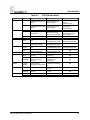
Revision History
Rev.
Date
1
July 2010
Initial Release
May 2011
Note added to Section 1.5.4.2. Note added to Section 2. Removed old
Section 2.4 "Train Detection in Double Crossover". Revised Section
6.5.1.1 and Section 6.5.2.1. Added Section 6.7.2. Revised Table 6-4,
Table 6-7, Table 6-9, and Table 6-12.
2
ii
Nature of Revision
SM 1F2.0001, Rev. 2, May 2011
Table of Contents
Table of Contents
1.
2.
3.
4.
GENERAL INFORMATION ............................................................................................................... 1-1
1.1. Safety Summary ....................................................................................................................... 1-1
1.2. Introduction ............................................................................................................................... 1-1
1.3. System Overview ...................................................................................................................... 1-2
1.4. Safety ........................................................................................................................................ 1-3
1.5. Physical Description ................................................................................................................. 1-4
1.5.1. Cardfile .......................................................................................................................... 1-4
1.5.2. Track Circuit System (TCS) .......................................................................................... 1-5
1.5.3. Power Supply ................................................................................................................ 1-7
1.5.4. Wayside Components ................................................................................................... 1-9
1.6. MICROLOK II - AF-902/904 Communications ........................................................................ 1-13
1.6.1. RS-485 MICROLOK Serial Protocol ........................................................................... 1-13
1.6.2. Microlok Peer Protocol ................................................................................................ 1-14
1.7. Specifications .......................................................................................................................... 1-16
1.7.1. Track Circuit ................................................................................................................ 1-16
1.7.2. Cardfile ........................................................................................................................ 1-16
1.7.3. Coupling Unit .............................................................................................................. 1-16
1.7.4. 350 or 500 MCM Bond ................................................................................................ 1-16
1.8. References.............................................................................................................................. 1-17
TYPICAL APPLICATIONS ................................................................................................................ 2-1
2.1. Mainline Track Circuits ............................................................................................................. 2-2
2.1.1. Track Circuit ID and Cab Signal Transmission ............................................................. 2-2
2.2. Yard Track Circuits ................................................................................................................... 2-4
2.3. Cab-Only Transmission in Crossovers ..................................................................................... 2-5
2.4. System Connection Diagrams .................................................................................................. 2-6
FUNCTIONAL DESCRIPTION .......................................................................................................... 3-1
3.1. Introduction ............................................................................................................................... 3-1
3.2. Wayside to Train Message Processing .................................................................................... 3-1
3.2.1. Message Data Processing ............................................................................................ 3-1
3.2.2. Equipment Room to Rails ............................................................................................. 3-1
3.3. Train Detection ......................................................................................................................... 3-2
3.4. Fail-Over ................................................................................................................................... 3-3
3.5. Microlok II Communications Link Monitoring ............................................................................ 3-3
USER INTERFACE............................................................................................................................ 4-1
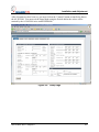
4.1. Integrated Web Server .............................................................................................................. 4-1
4.1.1. View Current Data Page ............................................................................................... 4-1
4.1.2. View Configuration Page .............................................................................................. 4-1
4.1.3. View Events Page ......................................................................................................... 4-1
4.1.4. Front Panel View Page ................................................................................................. 4-2
4.1.5. Setup ............................................................................................................................. 4-2
4.2. TCS Front Panel Operation ...................................................................................................... 4-2
4.2.1. Front Panel Displays ..................................................................................................... 4-2
SM 1F2.0001, Rev. 2, May 2011
iii
Table of Contents
5.
6.
7.
8.
iv
4.2.2. Controls ......................................................................................................................... 4-4
4.2.3. Restricted Access Menus ............................................................................................. 4-5
4.2.4. Main Menu .................................................................................................................... 4-5
4.2.5. Block Speed Menu ........................................................................................................ 4-5
4.2.6. Display Menu ................................................................................................................ 4-6
4.2.7. Events Menu ................................................................................................................. 4-6
4.2.8. Configuration Menu ...................................................................................................... 4-9
SERIAL AND NETWORK COMMUNICATIONS .............................................................................. 5-1
INSTALLATION AND ADJUSTMENT .............................................................................................. 6-1
6.1. Introduction ............................................................................................................................... 6-1
6.2. Recommended Test Equipment ............................................................................................... 6-1
6.3. Serial Link Termination ............................................................................................................. 6-1
6.4. Vital Parallel Output Terminations ............................................................................................ 6-3
6.5. System Setup Procedure Using the Network Interface ............................................................ 6-3
6.5.1. Configuration................................................................................................................. 6-3
6.5.2. Calibration ..................................................................................................................... 6-8
6.6. Detailed Calibration Procedure ................................................................................................. 6-9
6.6.1. Testing Codes and Abbreviations ............................................................................... 6-10
6.6.2. Test Equipment and Tools .......................................................................................... 6-11
6.6.3. Transmit Power Adjustments ...................................................................................... 6-11
6.6.4. Setup Overview........................................................................................................... 6-12
6.7. AF-902/904 Track Circuit System Setup and Test ................................................................. 6-13
6.7.1. AF-902/904 350 or 500 MCM Track Circuit Tuning .................................................... 6-14
6.7.2. Coupling Unit Tuning Theory ...................................................................................... 6-15
6.7.3. AF-902/904 350 or 500 MCM Rail Current Calibration .............................................. 6-16
6.7.4. AF-902/904 Cab Loop Current Calibration ................................................................. 6-19
6.8. Test Documentation and Data Sheets .................................................................................... 6-20
6.9. Example of a Record Keeping Policy ..................................................................................... 6-21
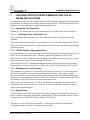
LIGHTNING PROTECTION RECOMMENDATIONS FOR AF-902/904 INSTALLATIONS ............. 7-1
7.1.1. Primary AC Line Protection .......................................................................................... 7-1
7.1.2. 120VAC Isolated (Ungrounded) Feed .......................................................................... 7-1
7.1.3. Secondary AC Line Protection ...................................................................................... 7-1
7.1.4. Signal Wiring ................................................................................................................. 7-1
7.1.5. Communication Ports ................................................................................................... 7-2
7.1.6. Microlok II Lightning Protection Considerations ........................................................... 7-2
PREVENTIVE MAINTENANCE ......................................................................................................... 8-1
8.1. Introduction ............................................................................................................................... 8-1
8.2. Importance of Preventive Maintenance .................................................................................... 8-1
8.2.1. Received Signal Level .................................................................................................. 8-1
8.2.2. Variance ........................................................................................................................ 8-4
8.2.3. Event Code Monitoring ................................................................................................. 8-6
8.3. Preventive Maintenance Tasks ................................................................................................ 8-6
8.3.1. Initial Preventive Maintenance Tasks ........................................................................... 8-6
8.3.2. Equipment Cleaning Procedure .................................................................................... 8-7
SM 1F2.0001, Rev. 2, May 2011
Table of Contents
8.3.3. Track Circuit Inspection ................................................................................................ 8-9
8.3.4. Track Circuit Checks ................................................................................................... 8-10
9. TROUBLESHOOTING....................................................................................................................... 9-1
9.1. Introduction ............................................................................................................................... 9-1
9.2. Approach to Troubleshooting ................................................................................................... 9-1
9.3. Troubleshooting Procedures..................................................................................................... 9-2
9.3.1. Fault Symptoms ............................................................................................................ 9-2
9.4. Front Panel Indicators and Controls ......................................................................................... 9-3
9.4.1. AF-902/904 TCS ........................................................................................................... 9-3
9.4.2. AF-902/904 Power Supply ............................................................................................ 9-5
10. CORRECTIVE MAINTENANCE ...................................................................................................... 10-1
10.1. Introduction ............................................................................................................................. 10-1
10.2. Replacement Repair ............................................................................................................... 10-1
10.2.1. AF-902/904 TCS and Power Supply Replacement .................................................... 10-1
10.2.2. Coupling Unit Replacement ........................................................................................ 10-2
10.2.3. Bond Replacement ..................................................................................................... 10-2
10.3. Verification of System Repair ................................................................................................. 10-2
11. TEKTRONIX SETUP PROCEDURE ............................................................................................... 11-1
12. PARTS LIST .................................................................................................................................... 12-1
12.1. Track Circuit Cardfile Overview .............................................................................................. 12-1
12.2. Track Circuit Cardfile .............................................................................................................. 12-1
12.3. Cardfile Motherboard Direction Relays ................................................................................... 12-3
12.4. AF-902 and AF-904 Cardfile PCBs ........................................................................................ 12-3
12.5. Coupling Units ........................................................................................................................ 12-3
13. RAIL TEAM AND TECHNICAL SUPPORT .................................................................................... 13-1
APPENDIX A CHARTS and TABLES .................................................................................................... A-1
SM 1F2.0001, Rev. 2, May 2011
v
Table of Contents
List of Figures
Figure 1-1.
Typical Wayside Room Equipment .................................................................................. 1-3
Figure 1-2.
AF-902/904 Cardfile Configuration .................................................................................. 1-5
Figure 1-3.
Track Circuit System (TCS) Front Panel.......................................................................... 1-6
Figure 1-4.
AF-902/AF-904 Power Supply ......................................................................................... 1-8
Figure 1-5.
Inductive Coupling Unit, Terminal Identification ............................................................... 1-9
Figure 1-6.
Direct Injection Coupling Unit, Terminal Identification ................................................... 1-10
Figure 1-7.
Typical "S" Track Cable Bond Application ..................................................................... 1-10
Figure 1-8.
Typical "I" Track Cable Bond Application ....................................................................... 1-11
Figure 1-10.
Typical Track Cable Bond Application – Direct Injection ............................................... 1-12
Figure 2-1.
Application of Cab Signal Frequencies to Track Circuits ................................................. 2-3
Figure 2-2.
Cab Signal Sequencing ................................................................................................... 2-3
Figure 2-3.
Single Rail Track Circuit ................................................................................................... 2-4
Figure 2-4.
Typical Interlocking Cab-Only Transmission Loop .......................................................... 2-5
Figure 2-5.
Inductive Coupling Unit, Terminal Identification ............................................................... 2-6
Figure 2-6.
Direct Injection Coupling Unit, Terminal Identification ..................................................... 2-7
Figure 2-7.
AFO-902 Motherboard VPO Jumpers and Terminating Resistors .................................. 2-8
Figure 2-8.
AF-904 Motherboard VPO Jumper and Terminating Resistors Detail ............................. 2-9
Figure 2-11.
AF-904 Track and AC Connections and Typical Wiring ................................................ 2-12
Figure 4-2.
Menu System Hierarchy ................................................................................................... 4-7
Figure 5-1.
RS-485 Communications ................................................................................................. 5-2
Figure 5-2.
Non-Redundant Peer Communications ........................................................................... 5-3
Figure 5-3.
Fully Redundant Peer Network Communications ............................................................ 5-4
Figure 6-1.
Typical Microlok II Master To AF-902/AF-904 Generation II Units Powered By Same
Battery (Microlok Protocol Or Half-Duplex Genisys Protocol) ......................................... 6-2
Figure 6-2.
Setup Page ...................................................................................................................... 6-5
Figure 6-3.
TCS Daughterboard Switch SW1 Location ...................................................................... 6-7
Figure 6-4.
AF-902/904 Upper Cardfile Rear Views......................................................................... 6-12
Figure 6-5.
AF-902 Track Circuit Data Sheet ................................................................................... 6-22
Figure 6-6.
AF-902 Cab Loop Data Sheet ........................................................................................ 6-23
Figure 6-7.
AF-904 Track Circuit Data Sheet ................................................................................... 6-24
Figure 6-8.
AF-904 Cab Loop Data Sheet ........................................................................................ 6-25
Figure 8-1.
Direct Injection AF-902/904 Track Circuit ........................................................................ 8-2
Figure 8-2.
Adjustment at High Ballast ............................................................................................... 8-3
vi
SM 1F2.0001, Rev. 2, May 2011
Table of Contents
Figure 8-3.
Adjustment at Low Ballast Auto Calibration ..................................................................... 8-4
Figure 8-4.
If Ballast Becomes High Auto Calibration ........................................................................ 8-4
Figure 8-5.
Meaning of the „Variance‟ Parameter............................................................................... 8-6
Figure 9-1.
AF-902/AF-904 TCS Front Panel ..................................................................................... 9-4
Figure 9-2.
AF-902/904 Power Supply Front Panel ........................................................................... 9-6
Figure 12-1.
AF-902 Track Circuit Cardfile ......................................................................................... 12-5
Figure 12-2.
AF-904 Track Circuit Cardfile ......................................................................................... 12-7
SM 1F2.0001, Rev. 2, May 2011
vii
Table of Contents
List of Tables
Table 4-1.
TCS LED Indications ........................................................................................................ 4-3
Table 6-1.
Network – Microlok Peer Protocol .................................................................................... 6-6
Table 6-2.
Track Circuit Ethernet Ports ............................................................................................. 6-6
Table 6-3.
Track ................................................................................................................................ 6-6
Table 6-4.
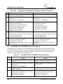
Entering AF-902/904 Front Panel Restricted Menu For Setup ...................................... 6-13
Table 6-5.
Entering AF-902/904 Setup Using the Web Server Interface ........................................ 6-13
Table 6-6.
Setting the Communications Address and Track Circuit ID ........................................... 6-14
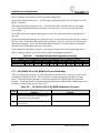
Table 6-7.
AF-902/904 350 or 500 MCM Tuning Instructions ......................................................... 6-14
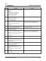
Table 6-8.
Coupling Unit (Nominal Capacitance Setting) ............................................................... 6-16
Table 6-9.
AF-902/904 350 or 500 MCM Calibration Procedure .................................................... 6-16
Table 6-10.
Rail Current Settings (350 MCM, 500 MCM, and Cab Loop Circuits) ........................... 6-18
Table 6-11.
Rail Current Settings (Direct Injection Circuits) ............................................................. 6-18
Table 6-12.
AF-902/904 Cab Loop Track Circuit Setup .................................................................... 6-19
Table 6-13.
AF-902/904 Direct Injection Track Circuit Setup ............................................................ 6-20
Table 8-1.
Key Preventive Maintenance Actions .............................................................................. 8-7
Table 9-1.
Basic Troubleshooting Concepts ..................................................................................... 9-1
Table 9-2.
Troubleshooting ............................................................................................................... 9-3
Table 11-1.
Tektronix Setup Procedure ............................................................................................ 11-2
Table 12-1.
AF-902/904 Track Circuit Cardfiles ................................................................................ 12-1
Table 12-2.
AF-902/904 Track Circuit Cardfiles ................................................................................ 12-1
Table 12-3.
Track Circuit Cardfile Parts List ..................................................................................... 12-1
Table 12-4.
Motherboard Direction Relays Parts List ....................................................................... 12-3
Table 12-5.
Cardfile PCBs Parts List ................................................................................................ 12-3
Table 12-6.
Coupling Units Parts List ................................................................................................ 12-3
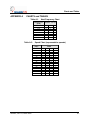
Table A-1.
Next Frequency Chart ......................................................................................................A-1
Table A-2.
Speed Chart (representative speeds) ..............................................................................A-1
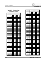
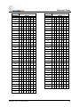
Table A-3.
Distance Chart (representative distance) ........................................................................A-2
viii
SM 1F2.0001, Rev. 2, May 2011
Introduction
1.
GENERAL INFORMATION
1.1. Safety Summary
Read and thoroughly understand this manual before attempting any of the procedures listed.
Pay particular attention to:
CAUTION
and
WARNING
These headings may appear throughout this manual. Caution statements indicate conditions that
could cause damage to equipment. Warning statements indicate conditions that could cause
physical harm, serious injury, or loss of life. Always observe standard precautions familiar to
trained electrical technicians. Always adhere to all safety regulations stipulated by the railroad.
1.2.
Introduction
This service manual is for the AF-902 and AF-904 Generation II Digital Frequency Shift Keyed
(FSK) Track Circuit Controller Systems. The AF-902 system is a fully redundant track circuit
controller with automatic fail-over operation. The AF-904 system is a non-redundant track
circuit controller. When describing features common to both systems, the term "AF-902/904" is
used.
The AF-902 and AF-904 Generation II Digital Frequency Shift Keyed (FSK) Track Circuit
Controller Systems provide a plug-in upgrade to the prior version of the AF-902/904 systems. A
new single module called a Track Circuit System (TCS) replaces the CPU and Auxiliary boards.
The Generation II system supports all of the previous communications and track signal features
and adds several new Ethernet port features:
Optional singular or redundant Ethernet interface to the MICROLOK® II controller using
MICROLOK Peer Protocol. This option also provides 5-bit speed code data in the
messages.
Enhanced user interface using an integral web server. Using Microsoft's Internet
Explorer, the user can connect to the AF-902/904's web server to access all of the data
and calibration functions previously displayed only on the system's front panel.
Remote Monitoring via SNMP. Using this network standard remote monitoring protocol,
the user can view the status of many of the AF-902/904's key operating parameters. The
AF-902/904 system will also issue SNMP trap messages when system errors are detected.
®
MICROLOK is a registered trademark of Ansaldo STS USA, Inc.
SM 1F2.0001, Rev. 2, May 2011
1-1
Introduction
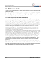
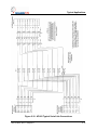
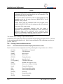
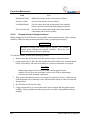
1.3.
System Overview
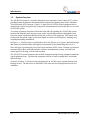
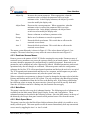
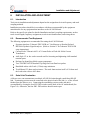
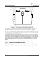
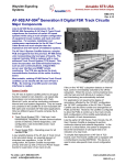
The AF-902/904 system is a wayside component of an Automatic Train Control (ATC) system,
providing both train detection and transmission of digital cab signaling data for the Automatic
Train Protection (ATP) function. Figure 1-1 shows the AF-902/904 related equipment that is
contained in a typical wayside room, using serial communications between the MICROLOK II and
AF-902/904 system.
To perform its primary functions of train detection and cab signaling, the AF-902/904 system
encodes data from the track logic processor on the wayside and transmits it through the track
where the signal is picked up and decoded by the car borne ATP equipment. This data is used
for direction, line speed, target speed, track length, next track circuit frequency, berthing, and
coupling/uncoupling information.
In Figure 1-1, vital track logic is performed by the Track MICROLOK II system. Interlocking logic
and control of switch machines and signals are performed by the Interlocking MICROLOK II.
Non-vital logic is performed by Non-Vital Logic Emulator (NVLE) units. Routing is performed
automatically by the train ID (through the wayside communications system), from the local
control panel, by fleeting, or from central control.
The AF-902/904 system comprises the trackside equipment and processing equipment within the
signal equipment room. The trackside equipment consists of track coupling units, wire bonds,
and track loops.
As shown in Figure 1-1 the processing equipment for an AF-902 system contains Primary and
Backup circuits. The MICROLOK II units and NVLE units may also be duplicated for fail-over
conditions.
1-2
SM 1F2.0001, Rev. 2, May 2011
Introduction
VITAL
CENTRAL
CONTROL
FACILITY
NON-VITAL
S
REMOTE
S
NVLE
INTERLOCKING
MICROLOK II
S
S
LOCAL
NVLE
S
SWITCH
MACHINES AND
SIGNALS
RELAYS
M
M
VITAL
S
TRACK
MICROLOK II
AF-902
M
LOCAL
CONTROL
PANEL
VITAL
SERIAL
LINK
S
PRIMARY
S
BACKUP
TRACK
CONNECTIONS
(350 OR
500 MCM
BONDS)
VITAL
PARALLEL
OUTPUTS
(where used)
CENTRAL
CONTROL
FACILITY
S
NON-VITAL
S
LOCAL
PC
M
S
TWC
A/B
LOOP
LEGEND:
S = SLAVE
M = MASTER
NVLE = NON-VITAL LOGIC EMULATOR
Figure 1-1. Typical Wayside Room Equipment
1.4.
Safety
Read and thoroughly understand this manual before attempting any of the procedures listed.
Pay particular attention to:
WARNING
and
CAUTION
statements that appear throughout this manual. Caution statements indicate conditions that could
cause damage to equipment. Warning statements indicate conditions that could cause physical
harm, serious injury, or loss of life. Always observe standard precautions familiar to trained
electrical technicians. Always adhere to all safety regulations stipulated by the railroad.
SM 1F2.0001, Rev. 2, May 2011
1-3
Introduction
1.5.
Physical Description
This section of the manual provides a brief description of the components of the AF-902 and AF904 Generation II Digital Frequency Shift Keyed Track Circuit Controller Systems.
CAUTION
This system operates directly from the AC mains. Use caution
when working near the backplane or on the power supply, and
especially when working on a TCS of Power Supply mounted on
an extender board.
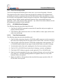
1.5.1. Cardfile
The AF-902/904 cardfile chassis is compatible with a standard 19-inch wide rack. All power is
supplied to the system circuit boards via the backplane motherboard. The cardfile requires two
115 VAC ± 10% at 50/60 Hz (nominal) power connections. Each line connection feeds power to
one half of a power supply which supplies the TCS with the required voltages. Both Primary
units in the AF-902 cardfile are powered from the same AC power feed. Both Backup units are
powered from the same, second AC feed.
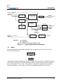
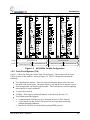
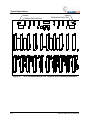
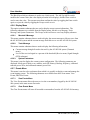
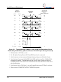
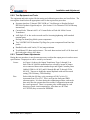
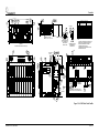
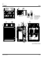
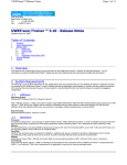
Figure 1-2 shows the layout of a AF-902/904 cardfile. Each cardfile contains six circuit boards,
all of which plug into the interconnecting motherboard mounted on the back of the cardfile.
In AF-902 systems, each cardfile contains two redundant track circuits. Each half of the cardfile
contains two TCS units and a single Power Supply. The Power Supply board provides two
independent supplies, for the Primary and Backup units of one track circuit.
The AF-904 cardfile has the same layout for four independent non-redundant track circuits. The
four TCS and two Power Supplies are configured as four separate track circuits.
The AF-902/904 is modular in design, which allows for easy removal and replacement of
individual circuit boards. Each TCS in an AF-902/904 system stores its configuration
parameters on an EEPROM mounted on the cardfile backplane. Replacement of a TCS may be
done with little reconfiguring. A calibration procedure must be performed to verify proper track
circuit operation. A full configuration and calibration must be performed whenever a new TCS
is used to replace the CPU and Auxiliary boards of an older system.
Connectors for the track circuit connection, serial communications to a MICROLOK II, calibration
jumpers, and AC power are on located on the rear of the cardfile.
1-4
SM 1F2.0001, Rev. 2, May 2011
Introduction
+15V
-15V
GND
WEST
DIRECTION
EAST
1
STATUS
2
U-LOK COM
3
LOCAL
BLK SPEED
REMOTE
RESET
RX/TX
ETHERNET 2
LINK
RX/TX
ETHERNET1
LINK
0
1
OFF
ON
ON-LINE
SELF
HEALTH
PARTNER
+15V
+5V
+15V
-15V
GND
WEST
DIRECTION
EAST
ON-LINE
SELF
HEALTH
PARTNER
1
STATUS
2
U-LOK COM
3
LOCAL
BLK SPEED
REMOTE
RESET
LEVEL
TRK CLEAR
DATA
LEVEL
TRK CLEAR
DATA
RX/TX
ETHERNET 2
LINK
RESET
RX/TX
ETHERNET1
LINK
XMFR
RESET
WEST
DIRECTION
EAST
1
STATUS
ON-LINE
2
U-LOK COM
3
LOCAL
BLK SPEED
REMOTE
RESET
RX/TX
ETHERNET 2
LINK
RX/TX
ETHERNET1
LINK
0
1
OFF
ON
SELF
HEALTH
PARTNER
MODE
LEVEL
TRK CLEAR
DATA
ENTER
AUX 2
MODE
ADJUST
+15V
-15V
GND
ETHERNET2
ADJUST
+15V
+5V
DOWN
ES PE
DOWN
1
DOWN
ES PE
ENTER
AUX 2
ENTER
AUX 2
1D2.0176.00
-15V
GND
0
1
0
1
ON
OFF
ON
ETHERNET2
ETHERNET2
ETHERNET1
ETHERNET1
TCS
TRACK CIRCUIT #1
TRACK CIRCUIT #1
LEVEL
TRK CLEAR
DATA
RESET
MODE
ADJUST
DOWN
ES PE
DOWN
1
ENTER
AUX 2
ETHERNET2
POWER SUPPLY
N12360501
TCS
AF-904:
+5V
+15V
POWER SUPPLY
N12360501
AF-902:
-15V
DOWN
1
OFF
ETHERNET1
LOCAL
BLK SPEED
REMOTE
RX/TX
ETHERNET1
LINK
XMFR
+5V
+15V
U-LOK COM
3
RX/TX
ETHERNET 2
LINK
RESET
ON-LINE
SELF
HEALTH
PARTNER
2
RESET
+5V
-15V
DOWN
1
1
XMFR
ADJUST
LEFT
POWER SUPPLY
DOWN
ES PE
WEST
DIRECTION
EAST
STATUS
XMFR
MODE
RIGHT
POWER SUPPLY
+5V
+5V
-15V
LEFT
POWER SUPPLY
+15V
RIGHT
POWER SUPPLY
+5V
-15V
TRACK CIRCUIT #2
ETHERNET1
TCS
TCS
TRACK CIRCUIT #2
TRACK CIRCUIT #3
TRACK CIRCUIT #4
Figure 1-2. AF-902/904 Cardfile Configuration
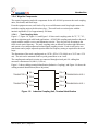
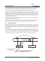
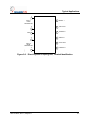
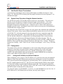
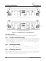
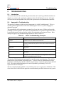
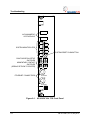
1.5.2. Track Circuit System (TCS)
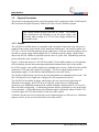
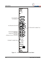
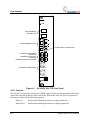
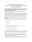
Figure 1-3 shows the front panel of the Track Circuit System. The location of these Track
Circuit Systems in the cardfile is shown in Figure 1-2. The TCS front panel contains the
following:
Two alphanumeric displays. These are used to monitor the data used in setup and
operation of the track circuit. The upper display is red and the lower display is green.
Four spring loaded, Up/Down toggle switches. These switches are used for inputting
data required for setup conditions.
A system Reset switch.
18 LEDs. These supply system information, as described in Section 4.2.1.
Two Ethernet ports that support:
Communications with MICROLOK II's using the MICROLOK Peer Protocol.
A user interface to the AF-902/904 system for local operation monitoring,
configuration and calibration.
Remote AF-902/904 system monitoring using SNMP protocol.
SM 1F2.0001, Rev. 2, May 2011
1-5
Introduction
ALPHANUMERIC
LED DISPLAYS
WEST
DIRECTION
EAST
STATUS
SYSTEM MONITOR LEDS
1
SELF
HEALTH
PARTNER
2
U-LOK COM
3
LOCAL
BLK SPEED
REMOTE
RESET
RX/TX
ETHERNET 2
LINK
RX/TX
ETHERNET1
LINK
CONFIGURATION SETUP
SWITCHES
MOMENTARY CONTACT
SWITCHES
(SPRING RETURN TO CENTER)
ETHERNET CONNECTORS
ON-LINE
LEVEL
TRK CLEAR
DATA
RESET
MODE
ADJUST
DOWN
ES PE
DOWN
1
ENTER
AUX 2
SYSTEM RESET PUSHBUTTON
ETHERNET2
ETHERNET1
1D2.0175.00
TCS
Figure 1-3. Track Circuit System (TCS) Front Panel
1-6
SM 1F2.0001, Rev. 2, May 2011
Introduction
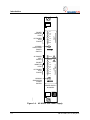
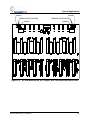
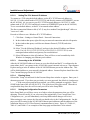
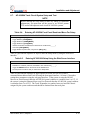
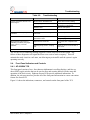
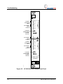
1.5.3. Power Supply
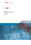
Figure 1-4 shows the front panel of the Power Supply. The location of the power supplies in the
cardfile is shown in Figure 1-2. Each power supply in the AF-902/904 system provides
regulated operating power for two TCS units.
WARNING
Dangerous voltages are exposed when operating the power supply
on an extender board. Use extreme caution when working near
exposed terminals. Failure to do so could result in serious physical
injury or loss of life.
The Power Supply front panel contains the following:
Six LEDs. Three LEDs monitor left track circuit power and three monitor right track
circuit power.
Two separate power switches. The upper power switch energizes the TCS to the
immediate right of the Power Supply and is marked with a right arrow. The lower power
switch energizes the TCS to the immediate left of the Power Supply is marked with a left
arrow. These switches are locking-lever type switches that must be pulled out to change
position.
Twelve voltage test points. There are four DC and two AC test points for each subsystem
supply.
SM 1F2.0001, Rev. 2, May 2011
1-7
Introduction
+15V
-15V
+5V
DC POWER
TEST
POINTS
GND
0
1
OFF
ON
AC POWER
TEST
POINTS
XMFR
XMFR
POWER
MONITOR
LEDS
+5V
+15V
-15V
+5V
DC POWER
TEST
POINTS
LOCKING
SUBSYSTEM
POWER
SWITCH
+15V
-15V
GND
0
1
OFF
ON
LEFT
POWER SUPPLY
LOCKING
SUBSYSTEM
POWER
SWITCH
+15V
-15V
RIGHT
POWER SUPPLY
+5V
POWER
MONITOR
LEDS
1D2.0181.00
POWER SUPPLY
N12360501
Figure 1-4. AF-902/AF-904 Power Supply
1-8
SM 1F2.0001, Rev. 2, May 2011
Introduction
1.5.4. Wayside Components
The required supporting trackside components for the AF-902/904 system are the track coupling
units, wire bonds, and track loops.
From the equipment room, track leads of up to several kilometers total loop length connect the
trackside coupling units to the direction relays. The track leads are twisted pairs with the
intrinsic impedance (Zo) of approximately 100 ohms.
1.5.4.1.
Track Coupling Units
Figure 1-7, Figure 1-8, Figure 1-9, and Figure 1-10 show track coupling units for "S", "I", "O",
and direct injection track cable bond applications. AF-902/904 coupling units interface the track
signals with the cardfile receiver and transmitter circuits. They also provide for tuning to the
track circuit carrier frequency. The track coupling units are housed in weather-tight enclosures
and consist of two independent and isolated signal coupling circuits. Each circuit has its own
transformer and a jumper-adjusted capacitor bank for frequency tuning as required for the track
loops.
The dimensions of the track coupling unit are 16"W x 8"H x 10"L (40.64 cm x 20.32 cm x 25.4
cm). The unit can be mounted on the wayside ground base or on a wall.
The coupling units and track circuits are connected through twisted pair #14 cabling that
measures a maximum of 6,000 ft. (1,830 m).
Figure 1-5 shows cabling terminal identification (Inductive Coupling), and Figure 1-6 shows the
cabling terminal identification (Direct Injection).
TB1-1
TB2-1
TRANSMITTER 1
TRANSMISSION LOOP 2
TB1-2
TB2-2
TB1-3
TB2-3
TB1-4
TB2-4
TRANSMITTER 2
TRANSMISSION LOOP 1
Figure 1-5. Inductive Coupling Unit, Terminal Identification
SM 1F2.0001, Rev. 2, May 2011
1-9
Introduction
J1
1
DIRECT 1
6
INPUT 1
FROM
TRANSMITTER
J2
J1
2
J1
GND 3
7
J2
CAB LOOP 1
8
COMMON 1
J2
DIRECT 2
J1
9
4
J2
10
J2
INPUT 2
FROM
TRANSMITTER
11 COMMON 2
J2
J1
5
2A1.0025.00
CAB LOOP 2
Figure 1-6. Direct Injection Coupling Unit, Terminal Identification
TRAFFIC
23 FT. (7 M)
TRACK „A‟
Rx „B‟
Tx „A‟
TRACK „A‟ & ‟B‟ COUPLING
UNIT
350 OR 500 MCM
TRACK „B‟
MAX. 15 FT.
ONE-TURN
COUPLING
LOOP
(#6 AWG)
23 FT. (7 M)
Rx „C‟
Tx „B‟
350 OR 500 MCM
TRACK „C‟
TRACK „B‟ & „C‟ COUPLING
UNIT
LOOP CABLE
COLLAR FOR
CABLES
MAX.
6,000 FT.
BOND CABLE
AF-90X
TRACK
CIRCUIT
"B"
TWO TWISTED-PAIRS (#14 AWG)
TWO TWISTED-PAIRS (#14 AWG)
BOND AND LOOP
CABLE MOUNTING
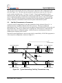
Figure 1-7. Typical "S" Track Cable Bond Application
1-10
SM 1F2.0001, Rev. 2, May 2011
Introduction
NEUTRAL CONNECTION
TO SUBSTATION
NEUTRAL CONNECTION
TO SUBSTATION
TRAFFIC
11.5 FT. (3.5M)
TRACK „A‟
TRACK „B‟
Rx „B‟
Tx „A‟
TRACK „A‟ & „B‟ COUPLING
UNIT
MAX.
6,000 FT.
350 OR 500 MCM
MAX. 15 FT.
ONE-TURN
COUPLING
LOOP
(#6 AWG)
Tx „B‟
Rx „C‟
TRACK „C‟
TRACK „B‟ & „C‟ COUPLING
UNIT
TWO TWISTED-PAIRS (#14 AWG)
TWO TWISTED-PAIRS (#14 AWG)
AF-90X
TRACK
CIRCUIT
“B”
Figure 1-8. Typical "I" Track Cable Bond Application
TRAFFIC
350 OR 500 MCM
350 OR 500 MCM
11.5 FT. (3.5M)
TRACK „A‟
TO SUBSTATION
(OPTIONAL)
TO SUBSTATION
(OPTIONAL)
Tx „A‟
INSULATED
JOINTS
Rx „B‟
TRACK „A‟ & „B‟ COUPLING
UNIT
MAX.
6,000 FT.
11.5 FT. (3.5M)
TRACK „B‟
NEUTRAL
CONNECTION
MAX. 15 FT.
ONE-TURN
COUPLING
LOOP
(#6 AWG)
Tx „B‟
INSULATED
JOINTS
Rx „C‟
TRACK „C‟
NEUTRAL
CONNECTION
TRACK „B‟ & „C‟ COUPLING
UNIT
TWO TWISTED-PAIRS (#14 AWG)
TWO TWISTED-PAIRS (#14 AWG)
AF-90X
TRACK
CIRCUIT
“B”
Figure 1-9. Typical "O" Track Cable Bond Application
SM 1F2.0001, Rev. 2, May 2011
1-11
Introduction
TRAFFIC
INSULATED
JOINTS
SIGNAL RAIL
TRACK „A‟
RETURN RAIL
TRACK WIRES (TYP. #6 AWG)
TRACK WIRES (TYP. #6 AWG)
MAX. 300 FT.
MAX. 300 FT.
TRACK „A‟ COUPLING UNIT
TRACK „A‟ COUPLING UNIT
MAX.
6,000 FT.
TWO TWISTED-PAIRS (#14 AWG)
AF-90X
TRACK
CIRCUIT
TWO TWISTED-PAIRS (#14 AWG)
Figure 1-10. Typical Track Cable Bond Application – Direct Injection
1.5.4.2.
350 or 500 MCM Bonds
Signals and messages in the rails are transmitted to and received from the AF-902/904 cardfile
via cabling type bonds known as "350MCM" or "500MCM" bonds. The actual bond type that is
used for an application depends on the current draw of the train motor. (Although similar, only
the 350 MCM bonds are addressed for the purpose of this discussion.) AF-902/904 track
coupling units are tuned to the carrier frequency and provide impedance matching to/from the
track.
NOTE
Within a limited range there may be several capacitance values that will
provide good signal transfer. The capacitance value that provides the best
performance at the carrier frequency can usually be found by tuning at a
frequency 400 Hz lower than the carrier frequency.
The 350 MCM (Thousand Circular Mils) bond consists of a few meters of 350 MCM cable
connected between the two rails in an "S", "I", or "O" shape, with the end of the "S", "I", or "O"
bonded to each rail. See Figure 1-7, Figure 1-8, and Figure 1-9. One-turn track loops are inside
the upper and lower parts of the "S" and inside the "O" part. As Figure 1-8 shows, the track
loops are on both sides of the "I" bond.
"S" and "I" bonds are used in areas where there are no insulated joints that define the track
circuit boundaries. "O" bonds are used in areas where an insulated joint is used in each rail to
define the track circuit boundaries. The AF-902/904 must be connected so that the track signal is
always injected into the track end farthest away from the end that the train is entering. The
direction relays mounted in the rear of the cardfile will switch the transmission direction based
upon the data in the message received from the vital wayside controller.
1-12
SM 1F2.0001, Rev. 2, May 2011
Introduction
1.6.
MICROLOK II - AF-902/904 Communications
Communication between the MICROLOK II and AF-902/904 system is conducted using either the
legacy RS-485 MICROLOK Serial Protocol or with the new MICROLOK Peer Protocol over an
Ethernet network. Each protocol has its own message data format and described in the sections
below. The most significant differences are; five bit speed code fields and the optional remote
block speed field used only in the Peer Protocol messages.
The part number of a TCS specifies the communication protocol and the encoding of speed and
distance codes. The communications protocol and related parameters are pre-programmed and
can only be changed by uploading a new Application Data package. The Application Data
package can also specify that neither protocol is selected. This option can be used when the
AF-902/904 system is used solely for train detection.
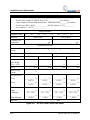
1.6.1. RS-485 MICROLOK Serial Protocol
When using the MICROLOK Serial Protocol, the MICROLOK II will periodically transmit data
messages to the AF-902/904. The AF-902/904 responds to the MICROLOK II, and logically
processes the data before repeatedly transmitting the data to track. This section lists the data
fields within these messages.
Details of the message formatting and data encoding for MICROLOK application programming is
provided in Appendix A.
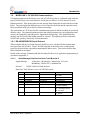
1.6.1.1.
Serial Message Data Received from Track Microlok II
Signal Message:
Protocol:
24 data bits, 8 header bits, 8 address bits, 24 Cyclic
Redundancy Check (CRC) validation bits
US&S Vital Serial Link protocol
Data from Track MICROLOK II to AF-902/904 system:
Bits
Name
Function
2
Direction
Traffic/Direction
3
7
4
4
1
Next Frequency
Target Distance to Go
Line Speed
Target Speed
Berthed
Next Frequency
Target Distance to Go
Line Speed
Target Speed
Berthed
2
Couple/Uncouple
Couple/Uncouple
1
Bifurcation
Bifurcation
SM 1F2.0001, Rev. 2, May 2011
Description
10 = East
01 = West
See Appendix A
See Appendix A
See Appendix A
See Appendix A
1 = train not in platform
0 = train in platform
10 = couple to train
01 = uncouple from train
00 = no action
1 = point N
0 = point R
1-13
Introduction
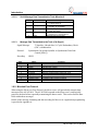
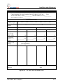
1.6.1.2.
Serial Message Data Transmitted to Track Microlok II
Bits
1.6.1.3.
Name/Function
1
Block Speed
1
Standby Health
1
Track Occupancy
1
Correspondence
4
Spare
Description
0 = block speed set
1 = no block speed set
0 = Standby unit not available
1 = Standby unit is available
0 = track occupied
1 = track unoccupied
0 = direction not in correspondence
1 = direction is in correspondence
Spare bits that are not used
Message Data Transmitted to the Track (Cab Signal)
Signal Message:
37 data bits, 8 header bits, 16 Cyclic Redundancy Check
(CRC) validation bits
Protocol:
Synchronous, bit oriented (similar to Synchronous Data Link
Control [SDLC])
Encoding:
NRZI
Bits
12
1
2
3
7
4
4
1
2
1
Name
Track Circuit ID
Primary/Backup
Direction
Next Frequency
Distance to Go
Line Speed
Target Speed
Berthed (Door)
Couple/Uncouple
Bifurcation
Function
Identification of present track circuit
Identification of which controller is providing the message
Train direction of travel
Carrier frequency of the next track circuit
Distance of target speed
Maximum speed permitted within track circuit
Desired speed at track circuit target
OK to open vehicle doors at station
Couple/Uncouple of trains for makeup
Bifurcation
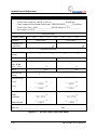
1.6.2. Microlok Peer Protocol
When using the MICROLOK Peer Protocol, the MICROLOK II will periodically transmit data
messages to the AF-902/904. The AF-902/904 responds to the MICROLOK II, and logically
processes the data before repeatedly transmitting the data to track. This section lists the data
fields within these messages.
Details of the message formatting and data encoding for MICROLOK II application programming
is provided in Appendix A.
1-14
SM 1F2.0001, Rev. 2, May 2011
Introduction
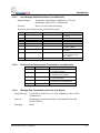
1.6.2.1.
Peer Message Data Received from Track Microlok II
Signal Message:
26 data bits, 8 header bits, 8 address bits, 24 Cyclic
Redundancy Check (CRC) validation bits
Protocol:
MICROLOK Peer Protocol message
Data from Track MICROLOK II to AF-902/904 system:
Bits
1.6.2.2.
Name
Direction
Traffic/Direction
3
7
5
5
1
Next Frequency
Target Distance to Go
Line Speed
Target Speed
Berthed
Next Frequency
Target Distance to Go
Line Speed
Target Speed
Berthed
1
Bifurcation
Bifurcation
2
Couple/Uncouple
Couple/Uncouple
5
Remote Block Speed
Remote Block Speed
Description
10 = East
01 = West
See Appendix A
See Appendix A
See Appendix A
See Appendix A
1 = train not in platform
0 = train in platform
1 = point N
0 = point R
10 = couple to train
01 = uncouple from train
00 = no action
See Appendix A
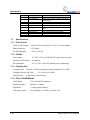
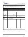
Serial and Peer Message Data Transmitted to Track Microlok II
Bits
1.6.2.3.
Function
2
Name/Function
1
Block Speed
1
Standby Health
1
Track Occupancy
1
Correspondence
4
Spare
Description
0 = block speed set
1 = no block speed set
0 = Standby unit not available
1 = Standby unit is available
0 = track occupied
1 = track unoccupied
0 = direction not in correspondence
1 = direction is in correspondence
Spare bits that are not used
Message Data Transmitted to the Track (Cab Signal)
Signal Message: 39 data bits, 8 header bits, 16 Cyclic Redundancy Check (CRC)
validation bits
Protocol:
Synchronous, bit oriented (similar to Synchronous Data Link
Control [SDLC])
Encoding:
NRZI
SM 1F2.0001, Rev. 2, May 2011
1-15
Introduction
Bits
1.7.
Name
12
1
Track Circuit ID
Primary/Backup
2
3
7
5
Direction
Next Frequency
Distance to Go
Line Speed
5
1
1
2
Target Speed
Berthed (Door)
Bifurcation
Couple/Uncouple
Function
Identification of present track circuit
Identification of which controller is providing
the message
Train direction of travel
Carrier frequency of the next track circuit
Distance of target speed
Maximum speed permitted within track
circuit
Desired speed at track circuit target
OK to open vehicle doors at station
Bifurcation
Couple/Uncouple of trains for makeup
Specifications
1.7.1. Track Circuit
Track Circuit Length:
1,000 ft. (305 m) maximum; 65 ft. (19.812 m) minimum
Shunt Sensitivity:
< 0.25 ohms
Pre/Post Shunting:
< 5.0 ft (1.524 m)
1.7.2. Cardfile
Power Input:
115 VAC ± 10% at 50/60 Hz (50 watts per track circuit)
Input Power Protection: 10 amp fuse
Environmental:
-25°C to 70°C with 95% humidity (non-condensing)
1.7.3. Coupling Unit
Coupling Feed:
6,000 ft. (1,800 m) maximum, with twisted pair of #14 AWG
Coupling Unit to Loop Feed:
Tuned Circuit:
< 15.0 ft (5 m) #14 AWG
Connected to one-turn loop
1.7.4. 350 or 500 MCM Bond
Cable Bond:
350 or 500 MCM conductive
Signal exchange:
Inductive Coupling
Impedance:
1.0 ohm (approximately)
Cab signal current:
105 milliamps at 9.5 kHz (see Table 6-11)
1-16
SM 1F2.0001, Rev. 2, May 2011
Introduction
1.8.
References
The following can be used as references:
ASTS USA Service Manual 8054 - Train to Wayside Communications (TWC) System
Wayside Equipment - Operation and Maintenance Service Manual
Refer to Specific site plans for detailed installation data and track coupling requirements.
SM 1F2.0001, Rev. 2, May 2011
1-17
Introduction
1-18
SM 1F2.0001, Rev. 2, May 2011
Typical Applications
2.
TYPICAL APPLICATIONS
This section provides an overview of the AF-902/904 system and its functional responsibilities
within the wayside application.
NOTE
For assistance regarding non-typical track circuits that are not described in
this manual, contact the Rail Team (see Section 13).
The AF-902/904 system has been designed as a communications interface between the
interlocking logic, processed by MICROLOK II units, and the equipment on the vehicle used for
controlling the movement and speed of a train. The AF-902/904 equipment takes serial input
from MICROLOK II, adds local track identification information, and transmits this combined data
to the train through the rails. The interface to MICROLOK II is a bi-directional serial link or
Ethernet link. The communications interface to the train is a one-way link where the car only
receives information.
The AF-902/904 equipment transmits, into one end of the track circuit, information such as track
circuit ID, target speed, line speed, distance-to-go, berthed, direction, next cab carrier frequency,
coupling/uncoupling, and bifurcation. It also monitors the other end of the track circuit to detect
train occupancy. Vital wayside logic is typically performed by the MICROLOK II system. A
typical wayside system is illustrated in Figure 1-1.
AF-902/904 circuits are used for both train detection and cab signaling. Crossovers and turnouts
use the power frequency track circuits for train detection and AF-902/904 cab loops for data
communications to the carborne ATC system. PF track circuits are described in ASTS USA
Service Manual 6087.
The AF-902/904 signals are coupled into the track via S bonds, O bonds, I bonds or direct
injection as described in Section 1.5.4.1.
When the AF-902/904 receiver senses a low amplitude or incorrect data, as compared to the
predetermined threshold level and track ID, it indicates that the track circuit is shunted by an
occupying vehicle.
As the vehicle travels from track circuit to track circuit, the car borne ATC system tunes a filter
on the vehicle receiver to the correct next frequency, allowing the vehicle to receive the data for
the correct track frequency only.
The vehicle's ATP subsystem decodes the vital track data to perform the ATP functions.
SM 1F2.0001, Rev. 2, May 2011
2-1
Typical Applications
2.1. Mainline Track Circuits
The AF-902/904 system is designed for simple, highly-reliable track interface applications using
jointless track circuits.
The carrier signals and modulated data signals are coupled to the rails via the 350 or 500 MCM
bond and coupling unit at each end of the track circuit. The amplitude of the carrier and the track
ID data signals is used to determine track occupancy. The modulated FSK data signal is used to
transmit vital and non-vital data to the vehicle.
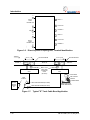
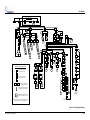
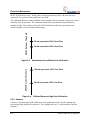
2.1.1. Track Circuit ID and Cab Signal Transmission
As the train travels from track circuit to track circuit within the mainline territory (station-tostation), track occupancy and isolation of commands between track circuits is accomplished by
alternating eight available data carrier frequencies. Frequencies range from 9.5 to 16.5 kHz in 1
kHz steps and are numbered F0 through F7. Three frequencies (F1, F3, and F5) are assigned to
westbound or northbound track circuits, and three frequencies (F2, F4, and F6) go eastbound or
southbound. The two remaining frequencies (F0 and F7) are usually used in special work areas.
Specifically, the layout of the mainline track circuits should follow the two three-frequency
rotations shown in Figure 2-1. If it is not possible to separate two track circuits of the same
carrier frequency by two intervening track circuits, then separation by one intervening track
circuit plus a set of insulated joints is acceptable.
As shown in Figure 2-1, carrier frequency F1 contains data that informs the train of the next cab
signal frequency (F3). Onboard the train, one receiver is tuned to F1 and the other to F3. As the
train approaches the 350 or 500 MCM bond, signal F1 drops out. Once valid data and level is
detected on F3, the vehicle ignores the data arriving from the old F1 receiver. The new data is
then decoded and the vehicle logic retunes the receiving filter (previously tuned to F1) to the
next cab signal frequency in the sequence of track circuit frequencies (refer to Figure 2-2).
The track circuit is arranged so that the train is always heading toward the transmitter. This is
controlled by the two assigned Direction Control bits within the message received from the
MICROLOK II.
Each wayside track circuit continuously transmits digitally-formatted data to the vehicle using
FSK modulation. The track MICROLOK II determines most of the information in the data bits and
passes this data on to each AF-902/904 track circuit, via vital serial or Ethernet communications
links, where the data is logically processed and encoded for the track message.
2-2
SM 1F2.0001, Rev. 2, May 2011
Typical Applications
T.C. “2103”
F1 = 10.5 kHz
T.C. “2102”
F3 = 12.5 kHz
T.C. “2101”
F5 = 14.5 kHz
T.C. “2100”
F1 = 10.5 kHz
T.C. “2099”
F3 = 12.5 kHz
REC. 1: F1
REC. 2: F3
TRAFFIC
DIRECTION
T.C. “99”
F4 = 13.5 kHz
T.C. “100”
F6 = 15.5 kHz
T.C. “101”
F2 = 11.5 kHz
T.C. “102”
F4 = 13.5 kHz
T.C. “103”
F6 = 15.5 kHz
TRAIN IN TRACK
CIRCUIT “2103”
RECEIVER #1 TUNED TO F1
RECEIVER #2 TUNED TO F3
APPROACH T.C. “2102” F1 OUT
F3 RECEIVED
T.C. “2103”
F1 = 10.5 kHz
T.C. “2102”
F3 = 12.5 kHz
T.C. “2101”
F5 = 14.5 kHz
T.C. “2100”
F1 = 10.5 kHz
T.C. “2099”
F3 = 12.5 kHz
REC. 1: F3
REC. 2: F5
T.C. “99”
F4 = 13.5 kHz
TRAFFIC
DIRECTION
T.C. “100”
F6 = 15.5 kHz
T.C. “101”
F2 = 11.5 kHz
T.C. “102”
F4 = 13.5 kHz
T.C. “103”
F6 = 15.5 kHz
TRAIN IN TRACK
CIRCUIT “2102”
1D2.0189.00
RECEIVER #1 TUNED TO F3
RECEIVER #2 TUNED TO F5
APPROACH T.C. “2101” F1 OUT
F5 RECEIVED
Figure 2-1. Application of Cab Signal Frequencies to Track Circuits
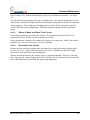
F1 RECEIVED
F3 RECEIVED
F3
350 OR 500 MCM BOND
TF
1
Figure 2-2. Cab Signal Sequencing
SM 1F2.0001, Rev. 2, May 2011
2-3
Typical Applications
The first eight bits are used for synchronizing the onboard decode function. The next 36 or 38
bits contain train control data. The last 16 bits of the message are the CRC bits for error
detection. Message configuration and bit assignments are described in Section 3.
Two types of speed restrictions are initiated by the ATC system: block speed restrictions and
zone speed restrictions. Block speed restrictions are selected by the Maintainer for each AF902/904 track circuit. Zone speed restrictions limit the target speed for a control line. The AF902/904 system enables the selection of the maximum line speed and target speed permitted to
be transmitted by a track circuit.
The Distance-to-Go bits represent the distance to the target speed, which is the desired speed of
the train at the end of the control line.
Train detection and signal communications are similar to those of the mainline continuous rail
territory, with the exception of the Berthed recognition bits contained in the message.
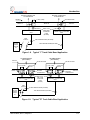
2.2.
Yard Track Circuits
In addition to their use for station-to-station operations, the AF-902/904 track circuits are also
used in storage yards, which are characterized by short track circuits and slow train movement.
Here, the system allows automatic movement of cars for the purpose of making up new train
configurations.
Yard track circuits use the same carrier frequency assignments and rotations as the mainline
track circuits: F1, F3, and F5 for west/north circuits and F2, F4, and F6 for east/south circuits.
However, for yard track circuits, it is only necessary to separate two track circuits of the same
carrier frequency by one intervening track circuit. Figure 2-3 shows this configuration.
INSULATED JOINTS
RUNNING
RAILS
TWC
LOOP
DIRECT INJECT
COUPLING UNIT
DIRECT INJECT
COUPLING UNIT
AF-902/904 MAIN DETECTION
AND CAB SIGNAL
Figure 2-3. Single Rail Track Circuit
2-4
SM 1F2.0001, Rev. 2, May 2011
Typical Applications
The cab signal is injected into the rails via direct-inject connection of the coupling unit to the
rails (See Figure 2-6). The direct injection method is used because only one rail of the track
circuit contains insulated joints. "S" bond, "O" bond, "I" bond coupling methods will not
function in areas where one rail of the track circuits are tied together. Vital commands such as
speed, coupling/uncoupling, and direction are transmitted to the vehicle via the cab signaling
system. Non-vital, bi-directional data, including vehicle health information, diagnostics, and
testing commands, is transmitted via the train-to-wayside communication system.
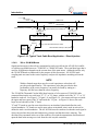
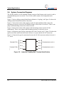
2.3.
Cab-Only Transmission in Crossovers
A typical crossover arrangement of a cab-only transmission loop is shown in Figure 2-4. A
transmission loop is installed within the rails of the crossover. The loop is transposed
approximately every 13 feet (4 meters) to prevent induced electrical interference between the cab
loop and the rails. The loop is connected to a coupling unit, which in turn is connected to the
output of one of the two transmitter groups. In these crossovers, train detection is done via
standard power frequency track circuits.
Note that in certain applications, crossovers may also be controlled by AF-902/904 equipment in
a direct injection configuration, as shown in Figure 2-3.
TO
RELAY ROOM
CU
F7
(TO COUPLING UNITS)
(TO COUPLING UNITS)
F4
F6
VANE
RELAY
(TO COUPLING UNITS)
F2
F6
F1
F3
TO
MICROLOK
60 HZ
F3
F5
(TO COUPLING UNITS)
(TO COUPLING UNITS)
(TO COUPLING UNITS)
Figure 2-4. Typical Interlocking Cab-Only Transmission Loop
SM 1F2.0001, Rev. 2, May 2011
2-5
Typical Applications
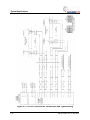
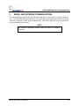
2.4. System Connection Diagrams
The AF-902 cardfile is a self-contained unit that consists of the Primary track circuit (A) and its
redundant Backup track circuit (B). The AF-904 cardfile contains four independent track
circuits.
Figure 2-5 shows cabling terminal identification (Inductive Coupling), and Figure 2-6 shows the
cabling terminal identification (Direct Injection).
Figure 2-7 shows the location of the jumpers on the AF-902 motherboard that connect the
terminating resistor(s) across the Vital Parallel Output (VPO) when it is not used. There is one
jumper and terminating resistor for each track circuit.
Figure 2-8 shows the location of the jumpers and terminating resistors on the AF-904
motherboard. There is one jumper and terminating resistor for each track circuit.
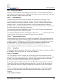
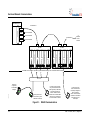
Figure 2-9 illustrates typical wiring connections for Track Circuits1 and 2. Figure 2-10shows the
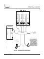
typical serial link connections between the MICROLOK II ports and the AF-902 connectors.
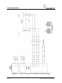
Figure 2-11 depicts the typical connections between the AF-904 connectors and track circuits 1,
2, 3, and 4.
TB1-1
TB2-1
TB1-2
TB2-2
TB1-3
TB2-3
TB1-4
TB2-4
TRANSMITTER 1
TRANSMISSION LOOP 2
2A1.0024.00
TRANSMITTER 2
TRANSMISSION LOOP 1
Figure 2-5. Inductive Coupling Unit, Terminal Identification
2-6
SM 1F2.0001, Rev. 2, May 2011
Typical Applications
J1
1
INPUT 1
FROM
TRANSMITTER
J1
2
J1
GND 3
CAB LOOP 1
8
COMMON 1
J2
9
4
J2
J1
5
DIRECT 1
7
J2
J1
INPUT 2
FROM
TRANSMITTER
2A1.0025.00
6
J2
10
J2
DIRECT 2
CAB LOOP 2
11 COMMON 2
J2
Figure 2-6. Direct Injection Coupling Unit, Terminal Identification
SM 1F2.0001, Rev. 2, May 2011
2-7
Typical Applications
JUMPER
TERMINATING RESISTOR
1D2.0172.00
JUMPER
TERMINATING RESISTOR
Figure 2-7. AFO-902 Motherboard VPO Jumpers and Terminating Resistors
2-8
SM 1F2.0001, Rev. 2, May 2011
Typical Applications
JUMPER
JUMPER
TERMINATING RESISTORS
JUMPER
1D2.0173.00
JUMPER
TERMINATING RESISTORS
Figure 2-8. AF-904 Motherboard VPO Jumper and Terminating Resistors Detail
SM 1F2.0001, Rev. 2, May 2011
2-9
Typical Applications
Figure 2-9. AF-902 Track and AC Connectors and Typical Wiring
2-10
SM 1F2.0001, Rev. 2, May 2011
Typical Applications
Figure 2-10. AF-902 Typical Serial Link Connections
SM 1F2.0001, Rev. 2, May 2011
2-11
Typical Applications
Figure 2-11. AF-904 Track and AC Connections and Typical Wiring
2-12
SM 1F2.0001, Rev. 2, May 2011
Functional Description
3.
FUNCTIONAL DESCRIPTION
3.1.
Introduction
The TCS receives vital data from the Track MICROLOK II, processes message speed and distance
data, adds local track circuit identification, and formats a track message. This message is then
sent to the train via the transmitter-end track coupling unit, bond and rail. The TCS monitors the
track signal via the receiver-end bond track coupling unit, to detect the presence of a train in the
track circuit. The TCS reports track circuit track occupancy to the MICROLOK II Vital
Interlocking Controller. The data message sent to MICROLOK II also contains the status of the
partner system health, direction relay correspondence, and local speed reductions. The message
to MICROLOK II is returned over the Ethernet or RS-485 data link. Occupancy status is also sent
to the MICORLOK II by a Vital Parallel Output (VPO) line.
3.2.
Wayside to Train Message Processing
3.2.1. Message Data Processing
When a signal is received from MICROLOK II, the TCS extracts the data from the MICROLOK
Serial Protocol or MICROLOK Peer Protocol message. The TCS vitally processes the message
data with past message data, and local track data stored in its Electrically Erasable
Programmable Read Only Memory (EEPROM).
Each of the four TCS's in a cardfile has its own EEPROM. The EEPROM data used in the
processing includes the unique 12-bit Track I.D. number, and possibly a local block speed
restriction. The EEPROM also stores configuration information for the unit, such as the
MICROLOK II slave address, I.P. addresses, carrier frequency, track circuit threshold voltages, and
other non-volatile information needed to operate the AF-902/904 system.
The AF-902/904 system compares the local and remote block speeds if set, to the MICROLOK II
message's Line Speed and Target Speed. If the local or remote block speed is slower than the
message Line or Target Speed then the slower speed will be transmitted to the track as the Line
and/or Target Speed. If the local or remote block speed is greater than that commanded by
MICROLOK II, or is not set, the MICROLOK II message's speed commands will be transmitted to the
track.
3.2.2. Equipment Room to Rails
From the relay/equipment room, track leads of up to several kilometers total loop length (3
kilometers of #10 gauge wire) connect the trackside coupling units to the direction relays. The
track leads are twisted pairs with intrinsic impedance (Zo) of approximately 100 ohms. The
coupling units are housed in weather tight enclosures and consist of two totally independent and
isolated coupling circuits. Each circuit has its own transformer and capacitor bank. The
transformer steps down the high voltage on the leads from the relay room to a low voltage
suitable for driving the single turn track loop. The capacitors are jumper-selected to tune the
track loop.
Tuning raises the reactance of the track loop to the selected carrier frequency. This raises
transmitter efficiency since smaller currents are required to flow in the long track leads.
SM 1F2.0001, Rev. 2, May 2011
3-1
Functional Description
Likewise, when a track loop has been selected to be a receiver, the low voltage from the track
loop is stepped up to drive the leads back to the relay room. The tuning of the track loop
provides a small increase in received signal strength. Due to the differences in transmitter and
receiver impedance, the coupling unit is adjusted, to provide some benefit to both transmitter and
receiver. The tuning is necessarily very broad and does not result in any appreciable frequency
selectivity between the jointless track circuits.
The AF-902/904 system does not use a conventional impedance bond. Instead, a few meters of
350 or 500 MCM cable are connected between the two rails in an "S" shape, with an end of the
"S" bonded to each rail. Single turn track loops are mounted inside of the upper and lower parts
of the "S." Currents circulating in the transmitting track loop are induced into the "S" and onto
the track. Likewise, currents from the track circulate in the "S" and are induced into the
receiving track loop. This type of bond has a strong directionality, with the ratio of the length to
the width of the "S" determining the "directivity" (like the front-to-back ratio on an RF
directional antenna). The track loop that transmits or receives is determined by the direction
relays on the rear of the cardfile.
3.3.
Train Detection
Each AF-902/904 system vitally monitors the status of a single track circuit. The audio
frequency carrier that is transmitted at one end of the track circuit and received at the other is
used not only for the digital cab signal data, but also for train detection. The carrier level and the
digital message are monitored by the receiver to determine track occupancy.
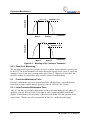
When a train shunts the rails of the monitored track circuit, the signal is blocked. This condition
is recognized by the receiving AF-902/904 circuits as a drop below a preset signal threshold and
is reported to the associated interlocking MICROLOK II system as an occupied circuit. The AF902/904 displays the track signal as a percentage of the shunt threshold. Signal levels at or
below 100% indicate an occupied track circuit. An unoccupied track circuit is nominally 162%
of shunt. This value will normally drift up and down as ballast conditions change.
Communications of track occupancy are sent to the vital MICROLOK II using the MICROLOK Peer
message over the Ethernet link or a MICROLOK Serial Protocol message over a RS-485 link.
Occupancy is also indicated on the DC voltage vital parallel output. This output can be
connected to a MICROLOK II Vital Input for faster occupancy state indication. While the shunting
train bridges adjacent track circuits, both are reported as occupied. When the train clears a track
circuit, the received signal threshold is restored and the AF-902/904 system responds
accordingly.
From the receive cable, the returning signal passes through an internal disconnect relay before
being applied to the receiver transformer. The receiver transformer has five taps. These taps
allowed the older AF-902/904 equipment to be adjusted for different operating conditions, such
as track lead length, direct injection vs. bond injection, and loop driving without a bond. The
AF902/904 Generation II system incorporates a self-adjusting receiver gain and requires that the
receiver tap on the rack always be set to the "2" position.
3-2
SM 1F2.0001, Rev. 2, May 2011
Functional Description
3.4. Fail-Over
The left TCS of each AF-902 track circuit is called the Primary, and the right pair is called the
Backup. These terms refer to the physical placement of the TCS. The unit that is operating the
track circuit is called the On-Line unit and the other unit is called the Standby or Off-Line unit.
This logical distinction is needed because a failed or powered-off Primary unit could be replaced
and/or powered up without it becoming the On-Line unit. The Primary unit would remain the
Standby unit until the power is cycled to both units or the Backup unit fails or is reset.
Each AF-902/904 TCS must pass its own continuous set of internal diagnostics. In AF-902
systems, if the On-Line track circuit controller fails, the Standby track circuit automatically
switches into operation.
3.5.
Microlok II Communications Link Monitoring
The AF-902/904 system continuously monitors the status of the communications with the
MICROLOK II. The following is a set of possible fault conditions that could be detected by an
AF-902/904 system. The faults pertain to master messages and peer messages sent by the
MICROLOK II to the AF-902/904 system.
Timeouts:
If an AF-902/904 system does not receive a valid message from the MICROLOK
II in 3 seconds, it will declare the link to be down.
CRC Mismatch: If a CRC does not match for a message received from MICROLOK II, the
AF-902/904 system will discard the invalid message.
Incorrect Length: If a response message from the MICROLOK II is either too long or too short
because of any data bytes or CRC mismatch, the incomplete message will
be discarded.
No Acknowledgment: If peer message acknowledgments are not received by the AF902/904 system from MICROLOK II, the AF-902/904 system will
declare the link to be down.
SM 1F2.0001, Rev. 2, May 2011
3-3
Functional Description
3-4
SM 1F2.0001, Rev. 2, May 2011
User Interface
4.
USER INTERFACE
4.1.
Integrated Web Server
The TCS front panel of the AF-902/904 system contains two Ethernet ports. Each of these ports
provide three communications features: MICROLOK Peer Protocol communications between the
AF-902/904 and the MICROLOK II, remote monitoring using SNMP, and a user interface web
server.
The web server provides the maintainer a convenient way to monitor system operation and to
configure and calibrate AF-902/904 system operational parameters using Microsoft's Internet
Explorer. All front panel operations can be accomplished through this web interface. The web
interface provides five primary pages. These pages are selected by clicking on one of the five
tabs on the upper right area of the main page.
4.1.1. View Current Data Page
The View Current Data page displays dynamic system data and is the AF-902/904's home page.
This page shows the data contained in the messages between the MICROLOK II and the AF902/904 and the track message. The data is displayed in decoded values as well as the binary bit
patterns for the data fields. The current shunt level and the track's signal variance is displayed at
the bottom of the page. Variance is derived from the amplitude difference between the track
signals mark and space frequencies. A small variance indicates that the coupling unit is well
tuned.
4.1.2. View Configuration Page
The View Configuration page displays static system configuration parameters. The parameters
associated with the communications to the MICROLOK II, Ethernet port addresses, SNMP
configuration, and track circuit identification and calibration setting are displayed. The AF902/904 system software components versions are also displayed.
4.1.3. View Events Page
The View Events page provides a display of the log of AF-902/904 system events, warnings and
critical errors. This data aids in diagnosing a malfunctioning system.
The user is given the option of setting a logging threshold for events. More detailed events are
logged at the higher thresholds.
Logging Threshold 2:
Logging Threshold 5:
Logging Threshold 8:
SM 1F2.0001, Rev. 2, May 2011
The TCS will only log critical system errors and warnings
Critical system errors, warnings, and informational events will be
logged
Additional operational information details will be logged such as
changes in message data.
4-1
User Interface
Logging Threshold 15: This level is designed to be used in detailed troubleshooting of
difficult problems with the guidance of Ansaldo Technical
Support. It displays many cryptic messages of system diagnostic
tests.
Logging Threshold 2 or 5 should be used for normal operation. Setting the threshold too high can
make it difficult to identify system faults among the lesser important informational events. The
time associated with each event is the time from the last reset.
4.1.4. Front Panel View Page
The Front Panel View page shows all of the data present on the front panel discrete LEDs and
the meaning of the LED states.
4.1.5. Setup
The Setup page provides password-protected entry to the pages used to configure and calibrate
an AF-902/904 system. Entry and detailed use of the Setup Mode pages are described in Section
6 of this manual.
4.2.
TCS Front Panel Operation
The front panel menu system of the AF-902/904 unit can also be used to modify and display vital
and non-vital system parameters and to calibrate and configure the system. It is provided for
compatibility with older AF-902/904 systems. Any operator can access any menu function
except for the configuration functions, which can be accessed only by authorized operators.
4.2.1. Front Panel Displays
The menu control system consists of two, four-character alphanumeric scrolling displays.
Discrete LEDs provide additional system operational mode and status information as listed in
Table 4-1. Figure 4-1 shows the switches and displays as well as the corresponding names and
identification.
4-2
SM 1F2.0001, Rev. 2, May 2011
User Interface
Table 4-1.
Group
LED
DIRECTION
STATUS
RESET
ETHERNET 2
ETHERNET 1
BLK SPEED
West/North Normal
relay dropped
E
East/South Reverse relay
picked
East/South Reverse
relay dropped
1
Failover link good
Failover link bad
2
Setup Mode
Normal mode vital
processors are healthy
3
RESET
For Future Use
TCS is Resetting
RX/TX
N/A
LINK
Physical connection to
network established
RX/TX
N/A
ON-LINE
SELF
Physical connection to
network established
TCS is on-line
Unit is functioning
correctly
The partner unit (for AF902) is functioning
correctly
U-LOCK
COMM
Communication
established to Microlok II
LOCAL
Block Speed Set is Local
REMOTE
TRK CLEAR
Off
West/North Normal relay
picked
PARTNER
U-LOK
COMM
On
W
LINK
ON-LINE
HEALTH
TCS LED Indications
LEVEL
DATA
Block Speed Set is
Remote
Track is Clear
Track is Clear
SM 1F2.0001, Rev. 2, May 2011
For Future Use
TCS not in Reset
Ethernet Interface is not
sending/receiving data
Ethernet Interface is not
sending/receiving data
Ethernet Interface is not
sending/receiving data
Ethernet Interface is not
sending/receiving data
TCS is off-line
Unit is off-line or not
functioning
THE partner unit (for
AF-902) is not
functioning
Communication not
established to Microlok
II
Local Block Speed is
not set
Remote Block Speed is
not set
Track is occupied
Track is occupied
Flashing
West/North Normal relay
picked
Track Shunted
East/South Reverse
relay picked
Track Shunted
N/A
Vital processors have
detected a warning or
error condition
For Future Use
N/A
Ethernet Interface is
sending/receiving data
N/A
Ethernet Interface is
sending/receiving data
N/A
N/A
N/A
N/A
N/A
N/A
N/A
N/A
N/A
4-3
User Interface
ALPHANUMERIC
LED DISPLAYS
WEST
DIRECTION
EAST
1
STATUS
SYSTEM MONITOR LEDS
U-LOK COM
3
LOCAL
BLK SPEED
REMOTE
RESET
RX/TX
ETHERNET1
LINK
ETHERNET CONNECTORS
SELF
HEALTH
PARTNER
2
RX/TX
ETHERNET 2
LINK
CONFIGURATION SETUP
SWITCHES
MOMENTARY CONTACT
SWITCHES
(SPRING RETURN TO CENTER)
ON-LINE
LEVEL
TRK CLEAR
DATA
RESET
MODE
ADJUST
DOWN
ES PE
DOWN
1
ENTER
AUX 2
SYSTEM RESET PUSHBUTTON
ETHERNET2
ETHERNET1
1D2.0175.00
TCS
Figure 4-1. AF-902/AF-904 TCS Front Panel
4.2.2. Controls
The AF-902/904 system has four up-down SPDT toggle switches used to enter and examine data
used in the setup and operation of the track circuit. Each menu of the AF-902/904 system uses
the control switches for the following purposes:
4-4
Mode Up
Scrolls forward through selections or display parameters.
Mode Down
Scrolls backward through selections or display parameters.
SM 1F2.0001, Rev. 2, May 2011
User Interface
Adjust Up
Increases the current parameter. Where appropriate, when the
maximum value is reached, the parameter rolls over to the
minimum value. In the Display submenus, the Adjust Up switch
is used to modify the display code.
Adjust Down
Decreases the current parameter. Where appropriate, when the
minimum value is reached, the parameter rolls over to the
maximum value. In the display submenus, the Adjust Down
switch is used to modify the display code.
Enter
Enters a submenu or confirms a parameter value.
Escape
Backs out of a submenu or cancels an operation.
Aux. 1
Enters the block speed menu. This switch has no effect on the
restricted access menus.
Aux. 2
Enters the block speed menu. This switch has no effect on the
restricted access menus.
The menus system Hierarchy is shown in Figure 4-2. The values shown in Figure 4-2 are
examples. The actual values may or may not be the same as those shown in Figure 4-2.
4.2.3. Restricted Access Menus
Remove power to the partner AF-902 TCS before entering the setup mode. Erroneous entry of
restricted access parameters may cause the system to behave in an unsafe manner. It is therefore
necessary that these parameters be configured only by qualified personnel. Restricted access
parameters can be modified only after a password is entered. Modified parameters can be made
operational only after all changes are confirmed. When an operator enters the configuration
submenu, the On-Line TCS will suspend normal operations and declare the track to be occupied.
The TCS suspends track transmission and MICROLOK II response, and all outputs are put into a
safe state. Normal operation resumes only after the system exits setup.
When a restricted access parameter is changed, it must be changed to the same value in both the
Primary and Backup units in an AF-902 system. The only exception is the Block Speed setting.
This value is communicated from the On-Line to the Backup unit. If the Primary and Backup
have different values at startup, the most restrictive (lowest) speed will be used by both units.
Since the AF-904 does not have a Backup unit, this function does not apply.
4.2.4. Main Menu
This menu is used to select a top level submenu function. The following top-level submenus are
available from the Main menu: Block Speed, Display, Events, and Configuration. These
submenu functions are described in the following sections. Since the Main menu is at the top of
the hierarchy, the Escape front-panel control switch position has no effect from this menu.
4.2.5. Block Speed Menu
This menu is used to select the Block Speed Adjust submenu from which it is possible to set or
modify a block speed. This menu option can also be entered immediately from any unrestricted
access menu by toggling the Aux 1 or Aux 2 switch.
SM 1F2.0001, Rev. 2, May 2011
4-5
User Interface
The Block Speed Adjust submenu is used to set a block speed. The Adj Up/Adj Dn switch
modifies the current value (the value displayed on the lower display), and the Enter switch is
used to enter the value. The operator must then confirm the value by toggling the Enter switch
again, or reject the value by toggling the Escape switch to exit.
4.2.6. Display Menu
This option contains submenus that are used to display current system information. The
following submenus are available from the Display menu: MICROLOK II Message, Track
Message, and System Parameters. The Escape switch will move out of any Display submenu.
4.2.6.1.
Microlok II Message
This menu contains submenus that are used to display the current message to MICROLOK II from
the AF-902/904 system and the current message from MICROLOK II to the AF-902/904 system.
4.2.6.2.
Track Message
This menu contains submenus that are used to display the following information:
Current message being delivered to the track by the AF-902/904 system (Transmit
menu).
Level of the received signal as a percent of the threshold (Receive menu, Signal Strength
(STR) submenu).
4.2.6.3.
System Parameters
This menu is used to display the current system configuration. The following parameters are
displayed: block speed, MICROLOK II address, track ID, Primary/ Backup, frequency, calibrated
transmit power West, and calibrated transmit power East.
4.2.7. Events Menu
This menu is used to select a submenu from which it is possible to display events and manage the
event logging system. The following submenus are available from the Events menu: View
Events, and Clear Events.
4.2.7.1.
View Events Menu
The View Events menu allows the user to view the event numbers (logged by the AF-902/AF904 system) in the most-recent-first order.
4.2.7.2.
Clear Events Menu
The Clear Events menu will erase all recorded event numbers from the AF-902/AF-904 memory.
4-6
SM 1F2.0001, Rev. 2, May 2011
User Interface
Leave web setup or timeout
IDLE
SCREEN
Web
enter
MAIN
MENU
ACCEPT
Displayed during Web Configuration and Calibration
BKSP
MENU
WEB
CFG
WAIT
Denied
DISP
MENU
EVNT
MENU
CNFG
MENU
Denied
Cancel
VIEW
EVNT
Cancel
SYS
MENU
bksp
.35
Denied
TRK
MENU
PSWD
MENU
Done
pswd
AAAA
.35
.35
WAIT
Denied
bksp
35
Prot
eth
Mlok
1
Peer
104
TkID
2199
Prim
1
Freq
13.5
PwrW
10%
PwrE
10%
RX
MENU
TX
MENU
RX
MENU
#17
0033
#16
0059
TX
MENU
EW
Bksp
10
set
Nxfq
Hlth
15.5
ok
TD
Trk
9000
ok
LS
Crsp
65
0
TS
65
Brth
0
Cpl
0
Ucpl
0
Bifr
0
Str
xxx%
EW
10
Nxfq
15.5
TD
9000
LS
65
TS
65
Brth
0
Cpl
0
Ucpl
0
Bifr
0
DIR
Rx W
SET
UP
ACPT
MENU
CONFIRM
TUNE
MENU
MLOK
MENU
ID
MENU
Move from menu "A" to menu "B" by
depressing the "Enter" switch
B
Move from menu "B" to menu "A" by
depressing the "Escape" switch
freq
10.0
WAIT
WAIT
pwr
10%
Cancel
Invalid
pswd
AAAA
B
Move "left/right" with the "Mode - Up"
and "Mode - Down" switches
WAIT
Denied
Denied
Denied
1D2.0180.02
Move between stacked information menus with
the "Mode - UP" and "Mode - Down" switches
Note: When a menu allows a value to be adjusted, press the "ADJ - Up" to
increase the value and "ADJ - Down" to decrease the value.
New
Pswd
WAIT
pwr
10%
Denied
AAAA
AAAA
Denied
CALC
Rx E
CALC
Rx W
WAIT
WAIT
Levl
95%
Levl
98%
Vari
2%
Vari
2%
Shnt
162%
Shnt
162%
pswd
AAAA
Invalid
Denied
Denied
B
0
1
1
DIR
Rx E
A dashed line indicates the move will happen
automatically when the task is completed
A
0
Peer
Addr
pwr
10%
WAIT
Denied
1
1
WAIT
B
WAIT
Mlok
DIR
Rx W
TkID
2199
WAIT
2199
2199
freq
13.5
NEW
PSWD
Cancel
TkID
Cancel
Cancel
Cancel
freq
10.0
Denied
CALI
BRAT
Invalid
DIR
Rx E
Cancel
pwr
10%
UTIL
MENU
Cancel
addr
1
WAIT
AF-902 / AF-904 Menu System Navigation
A
System
Reset
Invalid
Peer
104
A
Sure
?
WAIT
#1
0033
Invalid
A
RSTR
MENU
Cancel
CONFIRM
Done
MLOK
MENU
CLR
EVNT
WAIT
WAIT
Denied
Done
Denied
User must execute
a system reset by
cycling power or
depressing the front
panel reset button.
ACC
EPT?
User must accept the calibration (Enter key) or
reject the calibration (Escape key).
Figure 4-2. Menu System Hierarchy
SM 1F2.0001, Rev. 2, May 2011
4-7/4-8
User Interface
4.2.8. Configuration Menu
This menu contains submenus that modify system parameters. The Password Entry submenu
allows the user to enter the password. The Restricted submenu option contains other submenus
that allow the user to modify critical system data.
4.2.8.1.
Password Entry
This submenu option is used to enter and validate the restricted access password. The 4character password is entered one character at a time. The active character flashes, while
inactive characters are displayed constantly. Initially, "AAAA" is displayed and the leftmost
character is active. The Adj Up/Adj Dn switches are used to advance the active character
through the elements of the password character set. The Enter switch selects the current value of
the active character and activates the next character.
The Password is stored in the EEPROM for each TCS. If the TCS requires replacement, the
password is retained for the cardfile slot position.
The initial AF-902/904 password is four underscore characters, "_ _ _ _". The password can be
changed through the front panel or using the Ethernet web server interface.
4.2.8.2.
Restricted Menu Option
This submenu option is used to select a restricted access submenu. If the proper password has
not been entered using the Password Entry menu, the submenus of the Restricted menu are not
available. If there is a Backup unit in an AF-902 system it must be turned off prior to entering
the Restricted menu. The following sections describe the submenus available from the
Restricted menu. Exiting from the Restricted menu will cause the unit to reset.
After entering the Restricted menu, two menu selections are available: Setup and Accept.
4.2.8.3.
Setup Menu
Selecting this menu, by toggling the Enter switch, will make five submenu selections available to
the Maintainer: Tune, MICROLOK II, ID, Utility, and Calibration.
4.2.8.3.1. Tune Menu
The Tune submenu is used to configure the AF-902/904 system for train detection and cab
signaling. The Tune menu contains several sequential submenus to be used in conjunction with
the track circuit setup and tuning procedure. Because of the sequential nature of the tuning
procedure, a menu item may have both a function and a submenu.
By using the Frequency Adjust menus, the user can change the carrier frequency in either the
West to East or East to West signal transmission direction. The Adj Up/Adj Dn switches are
used to modify the value that is displayed, and the Enter switch moves to the Power Output
menu.
The Power Output menus provide an adjustment of transmitter power. The Adj Up/Adj Dn
switches are used to modify the value that is displayed, and the Enter switch moves to the
submenu.
4.2.8.3.2. Microlok II Menu
SM 1F2.0001, Rev. 2, May 2011
4-9
User Interface
This menu permits the user to select the MICROLOK II Address Adjust submenu, which can be
used to change the MICROLOK II station address.
4.2.8.3.3. ID Menu
With the ID menu option, the user can enter the track identification number (1 to 4095).
4.2.8.3.4. Utility Menu
This menu can be used to access New Password.
The New Password function allows the user to change the default password. The password is
modified using the Adj Up/Adj Down switches and toggling the Enter switch sequentially
confirms each character. The Escape switch backs up by one character or cancels the operation
if the first character is displayed. After the password has been entered, the user is asked to
confirm the value. A password that is modified and then confirmed immediately becomes the
system password. The default password can only be restored by physically replacing the
EEPROM on the motherboard.
4.2.8.3.5. Calibration Menu
Via the Calibration menu, the user sets the operating parameters of the AF-902/AF-904 system.
The function and use of each submenu is described in Section 6.5.2 of this manual.
4.2.8.4.
Accept Menu
This menu is used to confirm the changes that have been made to the restricted access system
parameters. The Accept menu is a group of menus that sequentially prompt the maintainer to
confirm the modifications that have been made to the system parameters. The parameter
identifier is displayed first, followed by the new value shown on both the top and bottom
displays.
The operator must toggle the Enter switch to confirm that both displays indicate the correct
parameter or the Escape switch to abort the modification. After each modified parameter has
been confirmed, a Password Entry menu is activated. This menu is similar to the menu described
above. If the correct password is entered, the system parameters are written to the system
EEPROM and will be used for all subsequent operations.
4-10
SM 1F2.0001, Rev. 2, May 2011
Serial and Network Communications
5.
SERIAL AND NETWORK COMMUNICATIONS
The communications between the AF-902/904 and the MICROLOK II can be configured in many
ways. If the MICROLOK Serial Protocol is used, the front panel Ethernet ports can be wired to
a network to facilitate system setup and monitoring. This section provides several examples for
system communications wiring.
NOTE
All network equipment switches must be rated for 100BaseT
operation
SM 1F2.0001, Rev. 2, May 2011
5-1
Serial and Network Communications
MICROLOK II
Rx/Tx/RTS/CTS
332 CPU
COM1
COM2
To AF -90x Cardfiles
COM3
To AF -90x Cardfiles
COM4
To AF -90x Cardfiles
Rx/Tx/RTS/CTS
Rx/Tx/RTS/CTS
J4
J3
1
2
TCS
#2
1
TCS
#3
2
1
2
TCS
#4
1
POWER SUPPLY
TCS
#1
AF-90x
POWER SUPPLY
POWER SUPPLY
AF-90x
J4
TCS
#1
2
1
2
TCS
#2
1
POWER SUPPLY
J3
To
additional
AF-90x
Cardfiles
TCS
#3
2
1
2
TCS
#4
1
2
ETHERNET communication is optional. Only required if SNMP monitoring or use of web-based interface is desired.
Ethernet Switch
1D2.0177.00
Remote PC
configured to
monitor SNMP
messages.
Router (Can also be a
DHCP server to give IP
addresses to local PCs)
Local PC for web-tool access.
Can get network address from
DHCP (if present) or will need to
be manually configured for
network. Address of AF90x
hardware can be obtained with a
discovery tool or manual input.
Can access all HW on network.
Local PC for web-tool
access. Will will need to
be manually configured for
direct connection to
AF90x. Address of AF90x
hardware can be obtained
with a discovery tool or
manual input.
Figure 5-1. RS-485 Communications
5-2
SM 1F2.0001, Rev. 2, May 2011
Serial and Network Communications
J3
J4
TCS
1
2
TCS
1
POWER SUPPLY
POWER SUPPLY
AF-90x
TCS
2
1
2
TCS
1
2
MICROLOK II
332 CPU
1
...
Ethernet Switch
COM
Board
To more AF 90x or
MICROLOK II
2
1D2.0178.00
Remote PC
configured to
monitor SNMP
messages.
Local PC for web-tool access.
Can get network address from
DHCP (if present) or will need to
be manually configured for
network. Address of AF90x
hardware can be obtained with a
discovery tool or manual input.
Can access all HW on network.
Figure 5-2. Non-Redundant Peer Communications
SM 1F2.0001, Rev. 2, May 2011
5-3
Serial and Network Communications
No RS-485
Connections
J3
J4
AF-902
Optional Connection for Local PC
for web-tool access. Address of
AF90x hardware can be obtained
with a discovery tool or manual
input. Can access all HW on
network.
1
2
BACKUP
TCS
PRIMARY
TCS
1
1
2
POWER SUPPLY
PRIMARY
TCS
POWER SUPPLY
Digital FSK Track Circuit
Local PC for web-tool access.
Address of AF90x hardware can
be obtained with a discovery tool
or manual input. Can access all
HW on network.
BACKUP
TCS
1
2
2
Remote PC
configured to
monitor SNMP
messages.
Ethernet Switch - A
Ethernet Switch - B
STANDBY
ON-LINE
MICROLOK II
MICROLOK II
1D2.0179.00
COM
Board
2
1
332 CPU
332 CPU
1
COM
Board
2
Figure 5-3. Fully Redundant Peer Network Communications
5-4
SM 1F2.0001, Rev. 2, May 2011
Installation and Adjustment
6.
INSTALLATION AND ADJUSTMENT
6.1.
Introduction
Track circuit installation and adjustment depend on the assigned track circuit frequency and track
coupling methods.
Installation procedures should be in accordance with those recommended by the equipment
manufacturers for any equipment that interfaces to the AF-902/904 unit.
Refer to the specific site plans for detailed installation and track coupling requirements, such as
track circuit lengths, frequency assignments, track circuit identifications, and wiring sheets.
6.2.
Recommended Test Equipment
The following equipment is recommended for testing the AF-902/904 unit:
Spectrum Analyzer: Tektronix TDS 3012B or C Oscilloscope or Hewlett-Packard
HP3560A Dynamic Signal Analyzer. (Refer to Section 11 for Tektronix TDS 3012B
setup instructions.)
Current Probe: Tektronix A621 AC Current Probe or Fluke 80i 1000s Current
Transformer.
AAR Style 1/2 in. hex socket wrench used for loosening and tightening AAR standard
terminal posts.
Red tags for identifying failed system components.
Two VOLTREX 855-B Insulated Tip Plugs for Front Panel test probes.
Hand-held radios with 2-mile (3.2 km) range minimum.
Track Shunt 0.25 ohms total resistance. The track shunt resistor itself is 0.20 ohms and
the leads to the rails are 0.05 ohms.
6.3.
Serial Link Termination
A MICROLOK II can communicate to multiple AF-902/904 units through a multi-drop RS-485
link. Terminating resistors must be connected at the physical end of the link, i.e., at the AF unit
farthest from the MICROLOK II. Connecting the terminating resistors at the end unit is
accomplished by closing the four SW1 DIP switches on the back of the AF motherboard (See
Figure 6-4). Otherwise, the four SW1 DIP switches should remain open.
SM 1F2.0001, Rev. 2, May 2011
6-1
Installation and Adjustment
MASTER
MICROLOK II
CPU CONN. A
PORT 2
PORT 1
A20
E2
A22
E4
A16
A2
A18
A4
A24
C6
A26
C8
A28
C10
A30
C12
1D2.0348.00
_
A10
_
A12
E20
E20
C18, A32
C18, A32
AF-902/AF-904
GENERATION II
DA-15
FEMALE CONNECTOR
CONNECTION
TO ADDITIONAL
SLAVES
DCD-
RTSL
L
DCD+
RTS+
TXD-
RXDL
L
RXD+
TXD+
TXD-
RXDL
L
RXD+
TXD+
RTS-
DCDLM
L
RTS+
DCD+
CTS-
R
5
9
1
11
3
15
7
R
CTS+
5V
0V
GND
8
Figure 6-1. Typical Microlok II Master To AF-902/AF-904 Generation II Units
Powered By Same Battery (Microlok Protocol Or Half-Duplex Genisys Protocol)
1. Resistors (R) are 470 Ohm, ½ watt.
2. For full duplex Genisys Protocol RTS and DCD need not be connected.
3. Serial commons are interconnected through a battery that powers Microlok II units.
4. Load resistors (L) are provided by DIP Switch SW1 on the rear of the AF-902/AF-904
Generation II cardfile. The individual switches of SW1 must all be in the OPEN or
CLOSED position. The resistors are connected into the circuit when the switches are in
the closed position.
5. Load resistor (Lm) is 240 Ohm, ½ watt and is installed on master DCD only, as shown.
6. Do not connect COMMUNICATION COMMON to ground.
6-2
SM 1F2.0001, Rev. 2, May 2011
Installation and Adjustment
6.4.
Vital Parallel Output Terminations
A provision for terminating an unused vital parallel output is available (See Figure 2-7 and
Figure 2-8). When the VPO is unused, place the jumper for that track circuit in position 2-3 to
terminate the output.
6.5.
System Setup Procedure Using the Network Interface
The AF-902/904 system's TCS includes a built in web server user interface. The web-server
interface can be used instead of using the front panel toggle switch interface. A PC using
Internet Explorer web browser version 6.0 or later can be connected to the internal server
through the front panel or the Ethernet port. Connection can be a direct cable connection or
through a network switch. An Ethernet switch can be used to access any one of an installation's
AF-902/904 from a single location.
The Setup tab on the AF-902/904 web page is the entry point to the calibration and configuration
features of the system. Entry is password protected and also requires the user to be close to the
AF-902/904 TCS. After the password is correctly entered, the user is required to toggle the
Enter switch on the front panel. This confirms that the user is working with the correct AF902/904 and that calibration or configuration is not being attempted from a remote location.
Be aware that most web browsers, like Internet Explorer will cache web pages. This can
possibly lead to the display of old data. When interfacing to the AF-902/904, caching should be
disabled. This is typically done in Internet Explorer by selecting Tools – General – Temporary
Internet files, Settings – under "Check for new version of stored pages", select "Every visit to the
page".
6.5.1. Configuration
This manual will use the term "configuration" to refer to the setting of all system operational
parameters except those associated with the frequency and power level of the track signal.
Configuration is typically performed only once, when the AF-902/904 system is initially
installed. Since the parameter values are stored in the cardfile EEPROM, the set parameter
values will be still be in effect if the TCS is replaced.
6.5.1.1.
Setting the AF-902/904 to the Default IP Address
When configuring a new system or if the IP addresses of a system have been lost, the default IP
addresses for the front panel Ethernet ports can be set by placing the #1 switch of switch bank
SW1 to the ON position and resetting the AF-902/904 system. SW1 is located near the front of
the CPU, daughter board on the TCS. The TCS power must be turned off before removing the
TCS from the cardfile to set the default IP address switch, SW1. The final switch position for
normal operation will be: SW1 switches #1 and 32 OFF, SW2 switch #2 OFF, and all other SW1
and SW2 switches in either the ON or Off positions.
The default IP address for ETHERNET1 is 169.254.1.10, and ETHERNET2 is 169.254.2.20. If
the IP addresses for your Ethernet ports are known, this step can be skipped.
SM 1F2.0001, Rev. 2, May 2011
6-3
Installation and Adjustment
6.5.1.2.
Setting The PC's Network IP Address
To connect to a TCS using the default address, set the PC's TCP/IP network address to
169.254.1.11 with a subnet mask of 255.255.255.0 and directly connect to ETHERNET1 port on
the AF-902/904. (Or you can set your PC's TCP/IP network address to 169.254.2.21 with a
subnet mask of 255.255.255.0 and directly connect to ETHERNET2 port on the AF-902/904.)
To use a non-default address, set the PC to an unused subnet address.
The direct-connection Ethernet cable (CAT-5) may be a standard "straight-through" cable or a
"cross-over" cable.
Proceed as follows to set a Windows PC's TCP/IP address:
7. Click Start – Settings or Control Panel – Network Connections
8. In the window that opens, right click on your network connection and select Properties.
9. In the window that opens, scroll down to Internet Protocol (TCP/IP) and select
Properties.
10. Select "Use the following IP address" and type in the desired IP address and Subnet
mask. Use 169.254.1.11 (255.255.255.0) or 169.254.2.11 (255.255.255.0) or an
unassigned subnet address and gateway for non-default use.
11. Select OK buttons to close all windows. There will be a several second delay while
Windows is changing your Ethernet port's address.
6.5.1.3.
Connecting to the AF-902/904
After the AF-902/904 IP address is known or set to the default and the PC is configured to the
same subnet, the PC can connect to the AF-902/904 system's internal web server. Open Internet
Explorer and type in the IP address of the AF-902/904 Ethernet port on the Address line. This
will be default address or your network's designated address. Internet Explorer should show the
View Current Data page for the AF-902/904.
6.5.1.4.
Entering Setup
Selected the "Setup" tab and wait for the Password drop-down window to appear. Enter your 4character password. If you have not previously set a new password, the default is 4 underscores
(_ _ _ _). If the correct password has been entered, you will be prompted to toggle the "Enter"
switch on the front of the AF-902/904 TCS. This is the lower left toggle switch. When this is
completed the drop down box will rise and you will be in the Setup Mode.
6.5.1.5.
Setting the Configuration Parameters
In the Setup Mode you will have a new set of tabs to select the parameters that you will be
adjusting. Please be careful, if you select one of the original tabs, View Current Data, View
Configuration, etc., you will immediately exit Setup Mode and all changes will be lost.
When setting up a new system, the first tab you should select is the Configuration tab. On this
page you will be setting up the AF-902/904's Ethernet port's addresses and the addresses of the
connection MICROLOK II's if Peer Protocol communications is in use. Figure 6-2, Table 6-1,
Table 6-2, and Table 6-3 are examples of the Setup page and data that is to be entered.
6-4
SM 1F2.0001, Rev. 2, May 2011
Installation and Adjustment
After all parameters have been set, you must click on the "Commit" button to transfer the data to
the AF-902/904. You must exit the Setup Mode using the Exit tab before the values will be
retained by the AF-902/904 in its cardfile EEPROM.
Figure 6-2. Setup Page
SM 1F2.0001, Rev. 2, May 2011
6-5
Installation and Adjustment
The Network – MICROLOK Peer Protocol table is replaced with a smaller table when the RS-485
MICROLOK Serial protocol is used. This table only requires you to enter the AF902/904's slave
address.
Table 6-1.
Network – Microlok Peer Protocol
Network – MICROLOK II
AF-90x PEER Address
MICROLOK II PEER Address
Normal MICROLOK II
I.P. Port
Standby MICROLOK II
I.P. Port
Normal MICROLOK II
I.P. Port
Standby MICROLOK II
I.P. Port
The AF-902/904's Peer Protocol Address.
The MICROLOK's Peer Protocol Address.
Controller I.P. Addresses, Ethernet1
The IP address of the MICROLOK II that is connected to the AF-902/904's
ETHERNET1 port.
This is the MICROLOK II's internal port address; it should be set to 60000 unless
the MICROLOK II's application program has defined a different port number.
The IP address of a second, standby MICROLOK II connected to the AF-902/904's
ETHERNET1 port. (If used)
This is the MICROLOK II's internal port address; it should be set to 60000 unless
the MICROLOK II's application program has defined a different port number. (If
used)
Controller I.P. Addresses, Ethernet2
The IP address of the MICROLOK II that is connected to the AF-902/904's
ETHERNET2 port. (If used)
This is the MICROLOK II's internal port address; it should be set to 60000 unless
the MICROLOK II's application program has defined a different port number. (If
used)
The IP address of a second, standby MICROLOK II connected to the AF-902/904's
ETHERNET2 port. (If used)
This is the MICROLOK II's internal port address; it should be set to 60000 unless
the MICROLOK II's application program has defined a different port number. (If
used)
The Track Circuit Ethernet Ports information must be provided by your systems network
designers.
Table 6-2.
Track Circuit Ethernet Ports
Track Circuit Ethernet Ports
Port 1 I.P. Address
Port 1 Subnet
Port 1 Gateway
Port 1 MAC Address
Port 2 I.P. Address
Port 2 Subnet
Port 2 Gateway
Port 2 MAC Address
The AF-902/904's ETHERNET1 port's IP address.
The subnet mask for ETHERNET1 port.
The gateway address for ETHERNET1 port.
The hardware address for ETHERNET1, this is not changeable.
The AF-902/904's ETHERNET2 port's IP address.
The subnet mask for ETHERNET2 port.
The gateway address for ETHERNET2 port.
The hardware address for ETHERNET2, this is not changeable.
Table 6-3.
Track
Track
Track I.D.
Track Circuit Name
6-6
The Track I.D. number that will be included in the Track Message. This number
must be assigned by the system designer.
This is text message displayed on the top of the web pages to help the maintainer
identify the specific track circuit.
SM 1F2.0001, Rev. 2, May 2011
Installation and Adjustment
After setting the configuration values, select the "Commit" button. A yellow banner will briefly
appear above the tables, confirming that the values have been sent from your PC to the AF902/904 for temporary storage. At this time you can set the SNMP parameters (provided by your
network designer) and set a new password if desired. These functions have tabbed pages in the
Setup Mode display.
1D2.0188.00
Upon completion of Configuration, you must exit the Setup Mode by selecting the Exit tab. You
will be presented with a page of all parameter values for review. If the all values are correct,
select the confirmation button and re-enter the system's password. This must be the same
password used to enter the Setup Mode. You will be prompted to reset the AF-902/904. This
can be done using the front panel reset button or cycling power to the AF-902/904. If you are
going to use the user-selected AF-902/904 IP settings, the default IP address switch (SW1-1)
(Figure 6-3) must be placed in the OFF position. The TCS must be removed from the cardfile to
access switch SW1. Remove power from the TCS before removing the TCS from the cardfile.
When power is turned back on to the TCS, it will use the IP network parameters that have been
set. Change your PC's address as described in Section 6.5.1.2 to operate in the same subnet as
the AF-902/904.
Figure 6-3. TCS Daughterboard Switch SW1 Location
SM 1F2.0001, Rev. 2, May 2011
6-7
Installation and Adjustment
6.5.2. Calibration
This section provides an overview to using the web page interface to calibrate an AF-902/904.
The web page interface provides an alternative to using the front panel interface to calibrate an
AF-902/904. The calibration procedure is the same for both interfaces. A detailed calibration
procedure is provided in Section 6.6.
NOTE
Before entering the setup mode to make any tuning or calibration
adjustments, you must turn off the power to an AF-902 partner
TCS and to both adjacent track circuit AF-902/904 systems.
Calibration of an AF-902/904 system involves three main steps as follows:
1. Tuning the bond for the maximum transfer of power to and from the track.
2. Setting the AF-902/904 transmission power to set the rail current to a level that assures
that a train reliably receives the track signal data.
3. Setting the AF-902/904 receiver signal to a level that provides reliable train occupancy
and broken rail detection.
6.5.2.1.
Tuning
Tuning adjusts the impedance of the bond to provide maximum transfer of the track signal to the
rail. It is typically performed at 400 Hz below the specified track carrier frequency: 9.5 kHz to
16.5 kHz. This will result in a low variance in the amplitude of the space and mark frequencies.
Both coupling units must be tuned, each when they are the receiving end of the circuit. Tuning is
typically only done during the initial installation of the track circuit. Retuning is usually only
needed if a bond is replaced or a high variance value is noted during the setting of the rail
current.
Prior to tuning a track circuit, place the TCS Tx jumper on the back of the AF-902/904 cardfile
to the 3 position and the Rx jumper to the 2 position.
Enter the Setup Mode as describe in Section 6.5.1.4 and select the Tuning tab. The Tuning page
provides the user with three controls; direction, frequency and power level. The frequency
should be set to 400 Hz below the designed track circuit carrier frequency. After changing the
controls, select the "Try" button to send the desired values to the AF-902/904 for transmission.
Specific steps and details of the tuning procedure are given in Table 6-7.
6.5.2.2.
Setting the Rail Current
Setting the rail current assures that the train is able to receive a reliable track signal. The
nominal value of IRAIL for each carrier frequency is listed in Table 6-10 and Table 6-11. The rail
current is set by adjusting the transmitter's power while measuring the bond current at the
receiver end of the track circuit.
Prior to making any adjustment, verify that the Rx tap on the rear of the cardfile is in the Tap 2
position.
6-8
SM 1F2.0001, Rev. 2, May 2011
Installation and Adjustment
Because of the large dynamic range imposed by the needs of different track circuits, the AF902/904 Control cardfile incorporates five adjustable transformer taps for TCS Transmitter
circuits. These allow for variables such as different track lead lengths. Adjustments are made
via jumpers on the cardfile backplane.
Output power is varied by two means:
Coarse:
Fine:
Output Transformer Taps (1 through 5) on back of the AF-902/904
motherboard. Taps act to double output amplitude with each increased setting.
(TXA= Primary; TXB = Backup)
Pulse width, the "ON" duty cycle percentage of a Full Cycle.
The Receiver Tap will always be set to Tap 2 position.
The AF-902/904 web interface provides a guided calibration procedure in the Setup Mode,
Calibration tab. You will be directed to set the specified track circuit frequency and then set the
transmitter power level in both directions. Transmitter power is roughly adjusted by using Tx
taps on the rear of the cardfile. The output power is double for each step of the Tx tap. Fine
adjustment is performed by adjusting the signals pulse width using the on screen power levels,
25 to 95%. The right side of the Calibration page provides a table listing the calibration values
from the last accepted calibration.
6.5.2.3.
Setting the Receiver Level
The AF-902/904 system will automatically adjust the receiver level during the completion of the
calibration sequence. The values of Variance, Gain, Rx Level, and Shunt Level are then
calculated for each direction and displayed on the web page.
When the AF-902/904 system performs the calculations, it assigns the current received signal
level to the 162% shunt level. Calibrations must always be performed at nominal track ballast
conditions. If you recalibrate a system under extreme ballast conditions, the AF-902/904 will
assign the 162% shunt level to an incorrect received signal level.
When the TCS is unable to calculate valid values for these parameters, it will display Variance,
Gain and Rx Level = 0 and Shunt Level as '---'. This would indicate an incorrectly wired or
adjusted track circuit, or it will be the normal and acceptable result of calibrating a Cab Loop
track circuit. Cab Loop track circuits do not have a received signal and do not determine
occupancy.
When the calibration is successful, the power levels and calculated values will be stored in the
TCS's EEPROM on the cardfile.
6.6.
Detailed Calibration Procedure
The first step in setting up a new or modified track circuit is to tune the track coupling units.
Tuning matches the impedance of the AF-902/904 to the bond impedance, allowing maximum
power transfer.
Tuning is done at the coupling units mounted near the track bond. The coupling unit contains
two identical circuits, which are separated by a dashed line down the middle of the PCB. The
operator should take care in determining which of these circuits is to be tuned before proceeding.
SM 1F2.0001, Rev. 2, May 2011
6-9
Installation and Adjustment
NOTE
The following procedures detail calibration using the front panel.
Calibration can also be done through the web server interface. The
same procedural steps are followed.
The two TCS units in an AF-902 system are distinguished by using
standard text for the left unit circuit and {BRACKETS} for the
{RIGHT UNIT} circuits.
Tuning affects both the transmitted and received signal levels,
making it MANDATORY that the tuning procedure be performed
first as part of the setup routine.
For preventive maintenance purposes, since the system is
operational and tuning has been completed at some earlier date,
calibration alone can be performed as the sensitivity check.
However, if calibration is marginal, it may be necessary to perform
both the tuning procedure and calibration procedures.
The detailed steps to tuning are provided in Table 6-7.
Calibration of the signal power must be performed after the tuning procedure since it is affected
by the resulting tuning signal levels. Specific steps and details of the calibration procedure are
given in Table 6-9.
6.6.1. Testing Codes and Abbreviations
6.6.1.1.
Controller Board Front Panel Display Abbreviation Codes
Basic character and case assignments used for performing the test procedures are as follows:
[AAAA]
[Aaaa]
[BKSP]
[MLOK]
[TUNE]
[Levl]
[CALI] [BRAT]
[Shnt]
[MLOK]
[aaaa]
[ID]
[tkid]
[PSWD]
[pwr]
[RSTR]
6-10
Upper Menu or Command
Label Parameter
Block Speed
MICROLOK II
Tuning Procedure
Input Rec Level
Calibration Procedure
Shunted with respect to Level
MICROLOK II Address Set Menu
Changeable Parameter
Track Circuit ID Set Menu
Track Circuit ID Parameter
Password
Output Pulsewidth
Restricted Menu
SM 1F2.0001, Rev. 2, May 2011
Installation and Adjustment
6.6.2. Test Equipment and Tools
The equipment and tools required for the tuning and calibration procedures are listed below. The
test engineer should select the appropriate tools for the required test procedure.
Spectrum Analyzer: Tektronix TDS 3012B or C Oscilloscope or Hewlett-Packard
HP3560A Dynamic Signal Analyzer. (See Section 11 for Tektronix TDS 3012B setup
instructions.)
Current Probe: Tektronix A621 AC Current Probe or Fluke 80i 1000s Current
Transformer
AAR Style 1/2 in. hex socket wrench used for loosening/tightening AAR standard
terminal posts
Red tags for identifying failed system components
Two VOLTREX 855-B Insulated Tip Plugs for system component Front Panel test
probes
Handheld radios with 2-mile (3.2 km) range minimum
Track Shunt 0.25 ohms total resistance. The track shunt resistor itself is 0.20 ohms and
the leads to the rails are 0.05 ohms.
6.6.3. Transmit Power Adjustments
During the test procedure, it may become necessary to adjust the output power in order to meet
specifications. Output power can be varied by two means:
Coarse:
As Figure 6-4 shows, the Output Transformer Taps (1 through 5) on
back of the AF-904/904 motherboard are selected by means of jumper
wires connected between the numbered taps and Signal Common points
(labeled COM for AF-902, and R1 through R4 and T1 through T4 for
AF-902). Taps act to double the output amplitude with each increased
setting (TXA=Primary; TXB=Backup).
Fine:
Pulse width, the ON duty cycle percentage of Full Cycle in 5%
increments from 25 to 95%. This is set from the front panel PWR
submenu option. It is done during the calibration procedure, and can be
done only after the operator has traversed the Configuration menu with
the correct password. There is a separate pulse width setting for each
direction of track circuit transmission. After these are SET and
ACCEPTED, they are stored in EEPROM.
SM 1F2.0001, Rev. 2, May 2011
6-11
Installation and Adjustment
VPO
TERMINATING
RESISTORS
3
3
3
3
2
2
2
2
R4
1
1
T4
R3
TRACK 4
TRK3&4
1
J4
1
J3
1
T3
5
5
5
5
4
4
4
4
3
3
3
3
2
2
2
2
1
1
1
1
T2
R1
R2
SW1
TRACK 3
TRACK 2
TX1
4
TX2
5
4
RX1
5
4
RX2
5
4
TX3
TX4
5
1
1
RX3
RX4
J2
VPO
JUMPERS
VPO
TERMINATING
RESISTORS
J1
VPO
JUMPERS
1
T1
TRACK 1
TRK1&2
AF-904 Upper Cardfile Rear View
VPO
TERMINATING
RESISTOR
VPO
TERMINATING
RESISTOR
3
3
3
3
2
2
2
2
1
1
1
1
COM
COM
1
J4
1
J3
SW1
5
5
5
5
4
4
4
4
3
3
3
3
2
2
2
2
1
1
1
1
COM
RXA
4
TXA
5
4
RXB
5
4
TXB
5
4
TXA
1
TXB
VPO
JUMPER
RXA
RXB
J2
5
J1
1
VPO
JUMPER
COM
TRK2
TRK1
AF-902 Upper Cardfile Rear View
Figure 6-4. AF-902/904 Upper Cardfile Rear Views
6.6.4. Setup Overview
There are several parts to the setup procedure, as described in the following subsections.
6.6.4.1.
350 or 500 MCM Bond Setup Procedure
To setup the AF-902/904 system using a 350 or 500 MCM Bond in either an "S" or "O" or "I"
configuration, follow the procedure given in Table 6-4, Table 6-5, Table 6-7, and Table 6-9, and
use the Data Sheet (Figure 6-5) at the end of this section. Setting the MLOK address and the
track circuit ID (Table 6-6) can be performed at any time in the sequence. Tuning (Table 6-7)
must be performed before calibration.
6.6.4.2.
Cab Loop Setup Procedure
Follow the procedure in Table 6-4 and Table 6-12, and use the data provided at the end of this
section. Setting the MLOK address and track circuit ID (Table 6-6) can be performed at any
time in the sequence. The AF-902/904 system performs track signal transmission only.
6.6.4.3.
Direct Injection Track Circuit
For setting-up the AF-902/904 system using a direct injection track circuit, follow the procedure
in Table 6-4, Table 6-6, and Table 6-13, and use the Data Sheet (Figure 6-6) at the end of this
section. Tuning is not required for a direct injection circuit.
6-12
SM 1F2.0001, Rev. 2, May 2011
Installation and Adjustment
6.7.
AF-902/904 Track Circuit System Setup and Test
NOTE
Before entering the setup mode to make any tuning or calibration
adjustments, you must turn off the power to an AF-902 partner
TCS and to both adjacent track circuit AF-902/904 systems.
Table 6-4.
Entering AF-902/904 Front Panel Restricted Menu For Setup
FRONT PANEL RESTRICTED MENU ACCESS PROCEDURE
From [MAIN][MENU] toggle ENTER
Toggle MODE to [CNFG][MENU]
Toggle ENTER for [PSWD][MENU]
Toggle ENTER for [pswd][AAAA]
ADJUST characters and ENTER, the default is four underscores (_ _ _ _).
Unit enters [RSTR][MENU]
Toggle ENTER. If pswd is OK, unit goes into [SET ][ UP ]
Table 6-5 provides the sequence of steps to enter the Setup mode by using the web server
interface.
Table 6-5.
Entering AF-902/904 Setup Using the Web Server Interface
SETUP MENU ACCESS PROCEDURE
SELECT the SETUP tab
ENTER the 4-character password, the default is four underscores (_ _ _ _)
Toggle the ENTER switch on the front of the AF-902/904 TCS
The drop down box will rise and you will be in the Setup Mode.
Table 6-6 provides the sequence of steps required to set the AF-902/904 system's
communications address and Track ID using the front panel interface. Section 6.5 describes
setting these parameters using the web page interface. If the system is using the RS-485
MICROLOK Serial Protocol then the AF-902/904 system's address is a number from 1 to 127. If
the system is using the Ethernet MICROLOK Peer Protocol then the AF-902/904 system's address
is a number from 1 to 65535. The Track ID number is a number between 0 and 4095 that is
assigned by the system architects and should be obtained from the track plan.
SM 1F2.0001, Rev. 2, May 2011
6-13
Installation and Adjustment
Table 6-6.
STEP
Setting the Communications Address and Track Circuit ID
SETTING THE COMMUNICATIONS ADDRESS
SETTING THE TRACK CIRCUIT ID NUMBER
1
Obtain track circuit MICROLOK Serial Protocol or Peer
address from hardware drawings.
Obtain track circuit ID from Control Line drawings.
2
Traverse restricted menu as described in Table 6-4.
[SET ][ UP ]
Toggle ENTER for [TUNE][MENU]
Traverse restricted menu as described in Table 6-4.
[SET ][ UP ]
Toggle ENTER for [TUNE][MENU]
3
Toggle MODE to [MLOK][MENU]
Toggle ENTER for [addr][ xx]
ADJUST addr (1-127) for Serial Protocol or
ADJUST the Peer address (1 to 65535)
Toggle ENTER for [MLOK][MENU]
Toggle ESCAPE for [SET ][ UP ]
Toggle MODE to [AC- ][CEPT]
Toggle MODE to [ ID ][MENU]
Toggle ENTER for [tkid][xxxx]
ADJUST tkid (0-4095)
Toggle ENTER for [ ID ][MENU]
Toggle ESCAPE for [SET ][ UP ]
Toggle MODE to [AC- ][CEPT]
4
Toggle ENTER for [CON-][FIRM]
Toggle ENTER to scroll through all parameter settings.
* Accept by toggling ENTER.
* Reject by toggling ESCAPE.
Toggle ENTER for [CON-][FIRM]
Toggle ENTER to scroll through all parameter settings.
* Accept by toggling ENTER.
* Reject by toggling ESCAPE.
5
If all parameters are CONFIRMED, unit will write setup
parameters to EEPROM and [DONE]
Toggle ENTER for system reset.
Record track circuit MLOK Addr on Track Circuit Data
Sheet (Figure 6-5).
If all parameters are CONFIRMED, unit will write setup
parameters to EEPROM and [DONE]
Toggle ENTER for system reset.
Record track circuit ID on Track Circuit Data Sheet
(Figure 6-5).
6.7.1. AF-902/904 350 or 500 MCM Track Circuit Tuning
For tuning of an AF-900/904 350 or 500 MCM track circuit, proceed with instructions in Table
6-7. The table lists the Operator's Action for tuning an AF-902/904 system using the front panel
interface. The web page interface provides a means to perform all of these steps from the one
tuning page in the Setup Mode, see Section 6.5.2.1.
Table 6-7.
STEP
AF-902/904 350 or 500 MCM Tuning Instructions
AF-902/904 OPERATOR'S
ACTION
TRACK/COUPLING UNIT TECHNICIAN'S
ACTION
Obtain track circuit frequency, (Fc) from Control Line
Drawings.
Set both coupling units to nominal capacitor
setting vs. frequency from Table 6-8.
2
Traverse restricted menu as described in Table 6-4 to
[SET ] [ UP ]
Toggle ENTER for [TUNE][MENU]
Verify that coupling unit JMP9 {JMP16} is set to
"NORM" position.
3
Toggle ENTER to automatically set direction of signal
Receive West (RxW)
Using Fluke Scopemeter 97 in Vac mode –
Monitor voltage at: TP2 and TP1 {TP5 and TP6}.
Toggle ENTER for [freq][0.0]
Toggle ADJUST to set frequency to Fc – 400 Hz.
Toggle ENTER for [pwr][ xx%]
Tune WEST coupling unit.
Vary capacitance with JMP1-JMP8 {JMP10JMP17} to peak voltage across:
TP2 and TP1 {TP5 and TP6}
1
4
Set pulsewidth to [pwr][50%]
6-14
SM 1F2.0001, Rev. 2, May 2011
Installation and Adjustment
STEP
AF-902/904 OPERATOR'S
ACTION
TRACK/COUPLING UNIT TECHNICIAN'S
ACTION
Unit is now transmitting.
5
Record final capacitance (E->W) on Track Circuit Data
Sheet (Figure 6-5).
6
Toggle ENTER to automatically set direction of signal
Receive East (RxE).
7
Toggle ENTER for [freq][ 0.0]
Toggle ADJUST to set frequency to Fc – 400Hz.
Toggle ENTER for [pwr ][ xx%]
Set pulsewidth to [pwr ][ 50%]
Unit is now transmitting.
8
Record final capacitance (E->W) on Track Circuit Data
Sheet (Figure 6-5).
9
Toggle ENTER to complete tuning sequence and
return to [TUNE][MENU]
Tune EAST coupling unit.
Vary capacitance with JMP1-JMP8 {JMP10JMP17} to peak voltage across:
TP2 and TP1 {TP5 and TP6}
6.7.2. Coupling Unit Tuning Theory
Changing the capacitance value in a coupling unit simultaneously tunes it to a different center
frequency and changes the efficiency of the tuned circuit. As you decrease the capacitance
value, both the center frequency and the circuit‟s efficiency increase. The result is that a
capacitance value selected by peaking the signal at track circuit center frequency will actually
result in a coupling unit that is tuned above track circuit center frequency.
Therefore, if you select a capacitance that gives the highest signal at some frequency below the
desired operational center frequency (Fc) you will have better performance at Fc. The best
overall offset is to set the tuning frequency to Fc – 400 Hz. If after calibration, you find that the
variance is higher than 7% you may want to re-tune the coupling unit. You will need to reduce
the capacitance by one or more increments to improve the variance. The new capacitance will
not provide the peak signal level at Fc; instead, the center of the coupling unit‟s passband will be
closer to Fc. To see if a change has been effective you must repeat the calibration of the AF902/904.
If you find a track circuit that is difficult to tune well enough to provide a low variance, you can
adjust the capacitance using the following fine-tuning procedure. Note that this is a more
intensive process and should only be used if the normal tuning or the normal tuning plus a one or
two step reduction in capacitance does not provide a satisfactory variance. The AF-902/904
system will accept variances up to 15% but it should be possible to achieve variances less than
10%.
To fine-tune a track circuit, you will need a means to measure the received signal, either at the
coupling unit or at the AF-902/904. You can measure the signal in the same manner as with
normal tuning. You will also find that fine-tuning is easier when using the web interface, but it
can be done using the front panel.
First peak the received track signal as described above at Fc – 400Hz.
SM 1F2.0001, Rev. 2, May 2011
6-15
Installation and Adjustment
Stay in either the web interface or the front panel tuning mode.
Adjust the tuning frequency to Fc – 200 Hz (Space) and measure the received signal level with
the AC voltmeter.
Then adjust the tuning frequency to Fc + 200 Hz (Mark) and re-measure the received signal
level. Be sure that the transmission is in the correct direction. You must always tune at the
receiver end.
If the Mark frequency is higher than the Space, reduce the capacitance in the coupling unit by
one step.
Repeat measuring and adjusting one capacitance step at a time until the Mark and Space are near
the same value. Remember that stepping the capacitance “one step” may involve selecting and
deselecting capacitors. Also, note that at the higher frequencies, a small change in capacitance
will have larger effect than at the lower frequencies.
If you change the capacitance and the Fc-200 (Space) frequency becomes greater than the Fc +
200 Hz (Mark) frequency, you are at or have passed the optimum capacitance.
Table 6-8.
Coupling Unit (Nominal Capacitance Setting)
NOTE: FINAL TUNED SETTINGS WILL BE NOMINAL ± 2.0 F (MICRO FARADS).
FREQ.(FC)
9.5kHZ
10.5
11.5
12.5
13.5
14.5
15.5
NOM. CAP.
20.0 F
17.33 F
15.00 F
13.00 F
11.00 F
9.47 F
8.47 F
16.5
7.33 F
6.7.3. AF-902/904 350 or 500 MCM Rail Current Calibration
Table 6-9 contains the sequence of actions that must be performed to set the correct rail current
for an AF-902/904 track circuit. The rail current is set by adjusting the transmitter's output
power. The table lists the Operator's Action for setting the rail current using the front panel
interface. The Setup Mode's Calibration page provides both a guide and the controls required to
perform all of these steps, see Section 6.5.2.2.
Table 6-9.
AF-902/904 350 or 500 MCM Calibration Procedure
STEP
AF-902/904 OPERATOR'S
ACTION
1
Prior to starting a calibration verify that the
Partner unit in an AF-902 system is turned OFF.
Set Receiver tap to the 2 postion.
2
Obtain track circuit frequency, (Fc) from Control
Line Drawings.
6-16
TRACK/COUPLING UNIT TECHNICIAN'S
ACTION
SM 1F2.0001, Rev. 2, May 2011
Installation and Adjustment
STEP
AF-902/904 OPERATOR'S
ACTION
3
Traverse restricted menu as described in Table
6-4 to
[SET][UP]
Toggle ENTER for [TUNE][MENU]
Toggle MODE to [CALI][BRAT]
Toggle ENTER for [freq][xx.x]
ADJUST frequency to Fc.
4
Toggle ENTER to automatically set direction of
signal Receive West (RxW).
Toggle ENTER for [pwr][xx%].
Unit is now transmitting.
5
Set Irail for E to W. using a combination of
selecting a transmitter tap and ADJUST [pwr ][
xx%],.
(For Irail setting, refer to Table 6-10 or
TRACK/COUPLING UNIT TECHNICIAN'S
ACTION
Using a Spectrum Analyzer with a Current Probe, attach
Probe to Center of 350 or 500 MCM Bond and
monitor/report rail current (Irail) at West track bond.
Table 6-11).
6
Record Irail, transmitter tap and pwr for E->W on
Track Circuit Data Sheet (Figure 6-5).
NOTE: At cross-bonding points, the S-bond is doubled.
The resulting Irail is the sum.
7
Toggle ENTER to automatically set direction of
signal Receive East (RxE).
Move to East track bond.
Using a Spectrum Analyzer with a Current Probe, attach
Probe to Center of 350 or 500 MCM Bond and
monitor/report rail current (Irail) at East track bond.
8
Toggle ENTER for [pwr][xx%].
Set Irail for W to E, using a combination of
selecting a transmitter tap and ADJUST [pwr ][
xx%],.
(For Irail setting, refer to Table 6-10 or
Table 6-11).
9
Record Irail and pwr on Track Circuit Data Sheet
(Figure 6-5)..
10
Toggle ENTER for [Levl][xx%].
Record receiver tap and Levl for W->E on Track
Circuit Data Sheet (Figure 6-5). The receiver tap
should be tap 2.
11
Toggle ENTER for [Vari][ x%]
Variance should be between 0 and 15%.
Record [Vari][ x%] for W->E
12
Toggle ENTER for [Shnt][151 - 171%]
The system will set the Shunt level to a nominal
162%
Record [Shnt][151 - 171%] for W->E when
unshunted.
13
Note: When SHUNT applied, check that [Shnt][
xx%] < 100%.
Record [Shnt][ xx%] when shunted
SM 1F2.0001, Rev. 2, May 2011
Apply 0.2 ohms shunt to track at center of East Bond.
6-17
Installation and Adjustment
AF-902/904 OPERATOR'S
ACTION
STEP
TRACK/COUPLING UNIT TECHNICIAN'S
ACTION
14
Toggle ENTER to automatically set direction of
signal travel (East to West)
15
Toggle ENTER for [Levl][xx%].
Record receiver tap and Levl for E->W on Track
Circuit Data Sheet (Figure 6-5). The receiver tap
should be tap 2.
Toggle ENTER for [Vari][ x%]
16
Variance should be between 0 and 15%.
Record [Vari][ x%] for E->W
Toggle ENTER for [Shnt][151 - 171%]
17
The system will set the Shunt level to a nominal
162%
Record [Shnt][151 - 171%] for E->W when
unshunted.
18
NOTE: When SHUNT applied, check that [Shnt][
xx%] < 100%.
RECORD [Shnt][xx%] when shunted.
19
If calibration is denied by the AF-902/904, the
display will show "Denied".
If calibration is accepted, the display returns to
Set-Up.
To exit, press ESC and then press Enter when
"Sure ?" is displayed. Or press ESC to device
calibration and return to Set-Up.
20
If all parameters are CONFIRMED, unit will write
setup parameters to EEPROM and [DONE].
Press RESET button for system reset.
21
After reset, system front panel LEDs should show
by being lit:
ON-LINE, SELF, U-LOK COMM, LEVEL, DATA.
Shunt track w/ 0.2ohms at West Bond.
Table 6-10. Rail Current Settings (350 MCM and 500 MCM Circuits)
FREQ.(FC) kHz
NOMINAL IRAIL
(mA)
9.5 kHz
105
NOMINAL IRAIL CURRENT ± 2 MILLIAMP.
10.5
11.5
12.5
13.5
95
87
80
75
14.5
15.5
16.5
70
65
60
Table 6-11. Rail Current Settings (Direct Injection Circuits)
FREQ.(FC) kHz
NOMINAL IRAIL
(mA)
6-18
9.5 kHz
105
NOMINAL IRAIL CURRENT ± 2 MILLIAMP.
10.5
11.5
12.5
13.5
95
87
80
75
14.5
15.5
16.5
70
65
60
SM 1F2.0001, Rev. 2, May 2011
Installation and Adjustment
For the AF-902, power down the Primary unit and repeat the calibration procedure for the
Backup unit.
NOTE
Backup unit must have same MLOK address, TRK ID, Fc,
password, and executive software version as the Primary unit.
6.7.4. AF-902/904 Cab Loop Current Calibration
Table 6-12 contains the sequence of actions that must be performed to set the correct rail current
for an AF-902/904 track circuit. The rail current is set by adjusting the transmitter's output
power. The table lists the Operator's Action for setting the loop current using the front panel
interface. The Setup Mode's Calibration page provides both a guide and the controls required to
perform all of these steps, see Section 6.5.1.5.
The AF-902/904 only transmits a track signal to the cab loop; it does not receive its signal so no
occupancy detection can occur. Therefore upon completion of calibration the AF-902/904
system will not have a valid receive level, variance or shunt level. These parameters will display
either a zero or "---" value on the front panel and web page displays.
Table 6-12. AF-902/904 Cab Loop Track Circuit Setup
STEP
AF-902/904 OPERATOR'S ACTION
Note: All cab loops employ a single coupling unit at the
transmit end.
1
Traverse restricted menu as described in
Table 6-4 to
[SET ] [ UP ]
Toggle ENTER for [TUNE][MENU] Toggle
MODE to [CALI][BRAT].
Toggle ENTER for [freq][xx.x].
ADJUST frequency to [freq][16.5] .
Toggle ENTER for [DIR ][E->W] (RxW).
Toggle ENTER for [pwr ][ xx%].
Check cab loop wiring to ensure proper connections.
AF-902/904 signal wire to 1,2 {4,5} .
Cab loop wire to 7,8 {10,11}.
3
Select appropriate transmitter tap and
ADJUST [pwr ][ xx%] to set ICabloop to
275mA for Cab loop.
Using a Spectrum Analyzer with a Current Probe, attach
probe to cab loop wire and monitor/report loop current (Iloop)
to the Train Control and Communications Building (TCCB).
Record Iloop, transmitter tap and pwr for
CAB LOOP on Track Circuit Data Sheet
(Figure 6-6).
If location is a double crossover, proceed to other cab loop.
4
5
Toggle ENTER for [DIR ][W->E] (RxE).
2
The AF-902/904 system does not receive a signal back from
the track.
Check cab loop wiring to ensure proper connections.
AF-902/904 signal wire to 1,2 {4,5} .
Cab loop wire to 7,8 {10,11}.
6
7
TRACK/COUPLING UNIT TECHNICIAN'S ACTION
Toggle ENTER for [pwr ][ xx%].
ADJUST [pwr ][ xx%] to the same "pwr"
value set in step 3.
Check that the ICabloop > 250mA.
SM 1F2.0001, Rev. 2, May 2011
Using a Spectrum Analyzer with a Current Probe, attach
Probe to Cab loop wire and monitor/report loop current
(Icabloop) to TCCB.
6-19
Installation and Adjustment
STEP
AF-902/904 OPERATOR'S ACTION
8
Record Icabloop and pwr on Cab Loop
Circuit Sheet.
9
If calibration is denied by the AF-902/904,
the display will show "Denied".
If calibration is accepted, the display
returns to Set-Up.
To exit, press ESC and then press Enter
when "Sure ?" is displayed. Or press ESC
to device calibration and return to Set-Up.
TRACK/COUPLING UNIT TECHNICIAN'S ACTION
Table 6-13. AF-902/904 Direct Injection Track Circuit Setup
STEP
AF-902/904 OPERATOR
Proceed step by step with the calibration
procedure in Table 6-9.
TRACK/COUPLING UNIT TECHNICIAN(S)
Proceed step by step with calibration procedure in Table
6-9.
Exception Notes:
(STEP 4 AND STEP 8)
Check coupling unit wiring.
AF-902/904 signal wire to 1, 2 {4, 5}
Track Inject wire to 6, 8 {9, 11}
Irail settings to be done with 0.20 ohm shunt in place across
rail at receive end.
Current transformer on shunt.
6.8.
Test Documentation and Data Sheets
The results of the setup and test procedures must be fully documented using the approved circuit
plans and the test Data Sheets. For specific information concerning a particular location‟s AF902/904 installation, refer to that location‟s circuit drawings, Book of Plans, test record sheets,
and any other installation data that may be available. The type of information that is available
may vary and depends on the railroad or transit authority‟s record keeping policy.
6-20
SM 1F2.0001, Rev. 2, May 2011
Installation and Adjustment
6.9.
Example of a Record Keeping Policy
The approved circuit test plans are used to record the results of the setup procedure. A circuit
that has been tuned only should be checked in blue. A circuit that has been both tuned and
calibrated should be checked in green. If corrections to the circuit plans are required as a result
of any procedure, the Test Engineer should document the changes using Yellow = Out and
Red=In color coding. In addition, the test engineer is required to initial and date the changes and
to further document the changes by using a Standard Discrepancy/Action Item List with the
installation test procedures to fully describe the discrepancy and the action taken.
The Data Sheets provided at the end of this section are used to record the results of the tests. The
top portion of the Data Sheet should be filled in before beginning the test. As part of this, the
test engineer should record the track circuit length and the approximate cable length from the
AF-902/904 to the nearest coupling unit.
Refer to the following test data sheets:
Figure 6-5.
Figure 6-6.
Figure 6-7.
Figure 6-8.
AF-902 Track Circuit Data Sheet
AF-902 Cab Loop Data Sheet
AF-904 Track Circuit Data Sheet
AF-904 Cab Loop Data Sheet.
SM 1F2.0001, Rev. 2, May 2011
6-21
Installation and Adjustment
AF-902 TRACK CIRCUIT DATA SHEET
Location __________________________________________________________
Track Circuit Length (65-1000 ft, 20-305 m)_______________Feet/Meters
Cable Length to Nearest Bond (6000 ft max, 1800 meters max)________Feet/Meters
Track Circuit ID# (1-4095)______________ MLOK Address (1-127)__________
Peer Address (1 - 65535) ______________
Tuning Procedure
Frequency (kHz)
9.5
Direction
Coupling Unit
Capacitance
10.5
11.5
12.5
13.5
14.5
15.5
16.5
West to East
East to West
___________________________ F
___________________________ F
Calibration Procedure
Transmitter Tap
Setting
Direction
1
2
3
4
West to East
5
East to West
AF-902 Unit
Primary
Backup
Primary
Backup
[pwr]
Pulse Width
(25% - 95%)
____________%
____________%
____________%
____________%
RAIL(mA)
___________mA ___________mA ___________mA ___________mA
Receiver Tap
Setting
Receiver Level
[Levl]
[Vari]
Shunt Level
[Shnt]
Unshunted
[Shnt] Shunted
2
____________%
8-55%
____________%
0-15%
____________%
8-55%
____________%
0-15%
____________%
8-55%
____________%
0-15%
____________%
8-55%
____________%
0-15%
____________%
151 - 171%
____________%
< 100%
____________%
151 - 171%
____________%
< 100%
____________%
151 - 171%
____________%
< 100%
____________%
151 - 171%
____________%
< 100%
Inspector___________________________________________
Date____________________
Figure 6-5. AF-902 Track Circuit Data Sheet
6-22
SM 1F2.0001, Rev. 2, May 2011
Installation and Adjustment
AF-902 CAB LOOP DATA SHEET
Location __________________________________________________________
Cable Length to Cab Loop Coupling Unit (65-1000 ft, 20-305 m)_____Ft/m
Track Circuit ID# (1-4095)____________ MLOK Address (1-127)___________
Peer Address (1-65535) ____________
Calibration Procedure
Frequency (kHz)
9.5
Transmitter Tap
Setting
1
10.5
11.5
12.5
2
Direction
13.5
3
14.5
15.5
16.5
4
West to East
5
East to West
AF-902 Unit
Primary
Backup
Primary
Backup
[pwr]
Pulse Width
(25% - 95%)
____________%
____________%
____________%
____________%
CABLOOP(mA)
250mA < I <
300mA
Receiver Tap
Setting
___________mA ___________mA ___________mA ___________mA
2
(Not Applicable)
Inspector___________________________________________
Date____________________
Figure 6-6. AF-902 Cab Loop Data Sheet
SM 1F2.0001, Rev. 2, May 2011
6-23
Installation and Adjustment
AF-904 TRACK CIRCUIT DATA SHEET
Location __________________________________________________________
Track Circuit Length (65-1000 ft, 30-305 m) _______________Feet/Meters
Cable Length to Nearest Bond (6000 ft max, 1800 meters max)________Feet/Meters
Track Circuit ID# (1-4095)______________ MLOK Address (1-127)__________
Peer Address (1-65535) ____________
Tuning Procedure
Frequency (kHz)
9.5
Direction
Coupling Unit
Capacitance
10.5
11.5
12.5
13.5
14.5
15.5
16.5
West to East
East to West
___________________________ F
___________________________ F
Calibration Procedure
Transmitter Tap
Setting
Direction
1
2
3
4
5
West to East
East to West
[pwr]
Pulse Width
(25% - 95%)
____________%
____________%
RAIL(mA)
___________mA
___________mA
Receiver Tap
Setting
Receiver Level
[Levl]
[Vari]
Shunt Level
[Shnt]
Unshunted
[Shnt] Shunted
2
____________%
8-55%
____________%
0-15%
____________%
8-55%
____________%
0-15%
____________%
151 - 171%
____________%
< 100%
____________%
151 - 171%
____________%
< 100%
Inspector___________________________________________
Date____________________
Figure 6-7. AF-904 Track Circuit Data Sheet
6-24
SM 1F2.0001, Rev. 2, May 2011
Installation and Adjustment
AF-904 CAB LOOP DATA SHEET
Location __________________________________________________________
Cable Length to Cab Loop Coupling Unit (65-1000 ft, 20-305 m)_____Ft/m
Track Circuit ID# (1-4095)____________ MLOK Address (1-127)___________
Peer Address (1-65535) ____________
Calibration Procedure
Frequency (kHz)
9.5
Transmitter Tap
Setting
1
10.5
12.5
2
Direction
[pwr]
Pulse Width
(25% - 95%)
CABLOOP(mA)
250mA < I <
300mA
Receiver Tap
Setting
11.5
13.5
3
14.5
15.5
16.5
4
5
West to East
East to West
____________%
____________%
___________mA
___________mA
2
(Not Applicable)
Inspector___________________________________________
Date____________________
Figure 6-8. AF-904 Cab Loop Data Sheet
SM 1F2.0001, Rev. 2, May 2011
6-25
Installation and Adjustment
6-26
SM 1F2.0001, Rev. 2, May 2011
Installation and Adjustment
7.
LIGHTNING PROTECTION RECOMMENDATIONS FOR AF902/904 INSTALLATIONS
All installations of AF-902/904 Systems should consider a lightning protection plan that includes
the protection of both the power wiring and the track signal wiring. The following sections are a
checklist of wiring configurations and recommended protection.
7.1.1. Primary AC Line Protection
Primary AC Line Protection refers to the protection of the AC Mains at the Service Entrance.
7.1.1.1.
Split Single Phase 120/240VAC Feed
This is a standard split single phase feed. The center of the 240VAC split is utility (earth)
grounded.
The recommended Primary Stage AC Line Protection is ASTS USA Part Number J7927360147.
This device is to be mounted directly to the Breaker Panel and wired to the main feeders through
dedicated breakers.
7.1.2. 120VAC Isolated (Ungrounded) Feed
Some Signal House AC Feeds are brought into the House through an Isolation Transformer. The
House side of that transformer will be a floating (neither side grounded), 120VAC feed.
If this isolated 120VAC feed never leaves the House, the Primary Protection device to be used at
the Service Panel is ASTS USA Part Number J7927360144.
If this isolated 120VAC is distributed throughout the House and leaves the House, the Primary
Protection device to be used at the Service Panel is the ASTS USA Part Number J7927360178.
7.1.3. Secondary AC Line Protection
The Secondary AC protection is for those lines carrying the “protected” AC Power coming into
the House, to remote devices or locations outside the Signal House. This power is usually
located on the main Terminal Board and on adjacent terminal posts. The preferred device to be
used as Line-to-Line protection is the ASTS USA Part Number J7927360181 but the ASTS USA
Part Number J7927360182 can also be used in most applications.
In the event a protected isolated AC feeder is sent outside the Signal House, then those lines
would also need to be protected Line-to-Ground. In either case, the protection devices are the
same as those mentioned above.
7.1.4. Signal Wiring
All track wires between the house and the AF-902/904 Coupling Units should be protected in a
Line-to-Ground configuration at the Main Terminal Board. The recommended Line-to-Ground
Protection Device is the ASTS USA Part Number J7927360180.
This device is a Gas Tube Arrester Assembly. It is designed to mount on standard AAR
Terminal posts that are spaced 2-3/8 inches center-to-center.
SM 1F2.0001, Rev. 2, May 2011
7-1
Installation and Adjustment
7.1.5. Communication Ports
Any communication lines leaving the Signal House should have Line-to-Ground Protection
using the ASTS USA Part Number J7927360180.
7.1.6. Microlok II Lightning Protection Considerations
Since the Ansaldo MICROLOK II Controller interfaces to the AF-902/904, it is important to
consider protection for the controller. In particular, protection should be provided for the House
Battery Feed to the MICROLOK II Controller. This will include both Line-to-Line (L-L) and Lineto-Ground (L-G) protection methods.
The recommended L-L protection device for the 12VDC Power to the MICROLOK II is the ASTS
USA Part Number J7257090519. This protector mounts onto standard AAR Terminal Posts on 1
inch centers.
The recommended L-G protection devices are Gas Tube Arrester assemblies, ASTS USA Part
Number J7927360180.
Be sure to have this protection as close to the MICROLOK II Cardfile as possible.
NOTE
To optimize the protection, the lines or line pairs must terminate at
the protection devices and from there, continue on to the
equipment. The protection device must not be connected via
branch (Tee) wiring.
7-2
SM 1F2.0001, Rev. 2, May 2011
Preventive Maintenance
8.
PREVENTIVE MAINTENANCE
8.1.
Introduction
This section describes the maintenance tasks required for the AF-902/904 track circuit unit,
coupler, and AF-902/904 350 or 500 MCM bond. These preventive maintenance tasks are to be
performed on as-scheduled basis, whereby the components are inspected, cleaned, tested, and
adjusted at periodic intervals to ensure the proper operation of the AF-902/904 unit.
8.2.
Importance of Preventive Maintenance
Regular Preventive Maintenance Inspection (PMI) can prevent failures and system malfunctions.
Maintenance personnel are responsible to keep the AF-902/904 unit in safe and satisfactory
operating condition at all times. This is accomplished through regular inspections, cleaning,
testing, and required adjustments of the unit. By maintaining up-to-date repair and PMI records,
and reviewing the history of these activities, maintenance schedules can be set to prevent circuit
performance deterioration. PMI can lead to the discovery of questionable conditions before
major malfunctions can occur, potentially causing train traffic problems and eventually total train
stoppage.
Track circuit bobbles can be minimized by both corrective and preventive maintenance practices.
Preventive maintenance is the monitoring of specific parameters in a timely manner. Corrective
maintenance is the replacement of a failed unit in a timely fashion.
There are several key parameters of the AF-902/904 track circuit that can be monitored to
determine the health of the track circuit. These parameters are displayed by the AF-902/904 and
can be checked by the maintainer.
The several major AF-902/904 track circuit parameters to be monitored are:
Received Signal Level - This parameter is important because it verifies that the received
signal level is within the operating range of the receiver circuit. An unoccupied track
circuit should have a received signal level between 8 and 55%.
Shunt Level – As with the Received Signal Level this value indicates the track signal
level. If the value changes to near 100% due to changes in ballast conditions, a
recalibration may be required or a false occupancy could be indicated.
Variance - This parameter can be used to determine whether the coupling unit is tuned
correctly or a coupling unit has failed. Variance can also indicate whether interference
from another source is becoming a problem in the reliable operation of the track circuit.
Events – The web page Events page displays the errors, warnings, and operational events
that have been detected by the AF-902/904 TCS. The most recent display is displayed
first.
8.2.1. Received Signal Level
A model of the AF-902/904 track circuit can be represented as shown in Figure 8-1. The rails
are represented by impedance ZR. „Bal‟ is the ballast resistance of the track circuit.
SM 1F2.0001, Rev. 2, May 2011
8-1
Preventive Maintenance
AF-902
Transmitter
Rail Impedance
ZR
ZR
AF-902
Receiver
Bal
RT
RR
S
Figure 8-1. Direct Injection AF-902/904 Track Circuit
The AF-902/904 receiver and its coupling unit are represented as impedance RR and the AF902/904 transmitter and its coupling unit are represented as a RT and source voltage S.
The value of the ballast resistance changes with time and the conditions of the ballast material
that supports the rails. The lower the value of ballast resistance, the lower the signal magnitude
received at the input of the AF-902/904 receiver.
The signal strength received at the input of the receiver is displayed on the web page and front
panel of the AF-902/904. The signal strength is displayed as a percentage of a shunt condition.
A value of 100% represents the highest received signal level (highest rail to rail impedance) that
will be detected as a shunt condition. Thus, values of signal strength should be much greater
than 100% when the track circuit is not occupied. Typical values of between 151-171% are
normal.
If the ballast becomes low, the percent displayed will be less than the normal value.
8.2.1.1.
Calibration During High-Ballast Conditions
The AF-902/904 track circuit is initially adjusted with high ballast resistance. The inherent
design of the AF-902/904 track circuit ensures that it functions correctly over a range of 100%162%, represented by a term called overdrive. This overdrive is illustrated in Figure 8-2.
8-2
SM 1F2.0001, Rev. 2, May 2011
AF902 Receiver Threshold
Preventive Maintenance
100 mA represents 100% Over Drive
62 mA represents 162% Over Drive
Adjustment at High Ballast
Figure 8-2. Adjustment at High Ballast
When the track circuit is initially adjusted (for example, a 10.5 kHz circuit) with high ballast
resistance, the threshold level of the track circuit‟s receiver is 100 mA. The 100 mA represents
an overdrive value of 1 or, expressed in percentage, 100%.
With only an overdrive of 100% (or 1), the track circuit would become occupied if the ballast
resistance changes to any lower value than assumed at the initial adjustment value. So it can
operate over a changing ballast value, overdrive is added to the track circuit. A track circuit with
no overdrive would operate very unreliably.
The overdrive can be achieved via increasing the source voltage OR decreasing the threshold
value of the receiver. With the AF-902/904 track circuit, overdrive is obtained by changing the
threshold of the receiver. Thus in the figure above, an overdrive value of 1.62 (or 162%) is
obtained by adjusting the receiver threshold to 62 mA. Note that the magnitude of overdrive is
selected as a function of frequency, shunting sensitivity, minimum ballast, rail-to-rail voltage,
etc.
Once the track circuit is adjusted with high ballast resistance, the received signal strength can
change as the ballast changes. The value of the received signal strength is displayed on the web
page and front panel of the AF-902/904.
If the track circuit is recalibrated, the threshold of the receiver will be changed. For example, if
the ballast value is low and the received signal level is 60%, performing recalibration will adjust
the threshold of the receiver to a new value.
Figure 8-3 shows the new threshold of the receiver. The new value is now 38 mA, which
represents a 162% overdrive value.
8.2.1.2.
Calibration During Low-Ballast Conditions
If after a calibration, the ballast would change back to a very high value, the overdrive may be
much more now than the 162%. See Figure 8-4.
As can be reasoned, the 38 mA threshold now represents an overdrive of 263% (2.63 = 100 mA /
38 mA). Because of the safety implications, the value of overdrive is continuously monitored by
SM 1F2.0001, Rev. 2, May 2011
8-3
Preventive Maintenance
the AF-902/904 track circuit. If this value exceeds approximately 180%, the track circuit is
„turned off‟ for a period of time and Error is recorded.
AF902 Receiver Threshold
The calibration function, when performed with low ballast, does not present a safety issue, only a
reliability issue in operation. The calibration should only be performed when the ballast is
nominal or high. The overdrive of the AF-902/904 should be sufficient to permit the track
circuit to operate over the complete ballast range.
62 mA represents 100% Over Drive
38 mA represents 162% Over Drive
AF902 Receiver Threshold
Figure 8-3. Adjustment at Low Ballast Auto Calibration
100 mA represents 100% Over Drive
38 mA represents 263% Over Drive
Figure 8-4. If Ballast Becomes High Auto Calibration
8.2.2. Variance
Variance is a measurement of the differences in the amplitudes in the wayside coupling unit
between the Mark and Space frequencies. The coupling unit is a LC circuit tuned to a specific
frequency.
8-4
SM 1F2.0001, Rev. 2, May 2011
Preventive Maintenance
If the variance is 0%, both the Mark and Space frequency amplitudes are identical. See Figure
8-5.
The AF-902/904 system employs two type of coupling units. One type of coupling unit is used
with S-bond, O-bond, and I-bond track circuits and requires being tuned to the specific operating
carrier frequency. The second type of coupling unit is used for all direct injection, single rail
AF-902/904 track circuit configurations. The direct injection coupling unit does not require
tuning.
8.2.2.1.
S-Bond, O-Bond, and I-Bond Track Circuits
If no in-band interference is present, the variance value obtained from the AF-902/904 is a
measurement of how well the wayside coupling unit is tuned.
If the coupling unit is slightly off in tuning, the variance is several percent. Ideally, the variance
should be zero. However, values up to 15% are acceptable.
8.2.2.2.
Direct-Inject Track Circuits
Because the direct injection coupling unit is not tuned, the variance measured with these track
circuits is very low. Typical values are between 0% and 5%, depending on the cable length
between the room and field-located coupling unit.
With no in-band interference, the variance value is a constant magnitude. However, if in-band
noise is present, the variance displayed by the AF-902/904 will vary between values, because the
noise adds and subtracts to the Mark and Space signal amplitudes.
SM 1F2.0001, Rev. 2, May 2011
8-5
Preventive Maintenance
Amplitude
Variance = 0%
Mark F
Space F
Frequency
Amplitude
Variance > 0%
Mark F
Space F
Frequency
Figure 8-5. Meaning of the ‘Variance’ Parameter
8.2.3. Event Code Monitoring
The web page interface provides a display of errors, warnings, and operational events detected
by the TCS. The Event threshold level can be adjusted to log only errors if set to 0, errors and
warnings if set to 2 and errors, warnings and events if set to 5. Higher levels will show and
excessive number of events and are only useful for advanced troubleshooting.
8.3.
Preventive Maintenance Tasks
Preventive maintenance tasks are to be performed on a scheduled basis, as described in this
subsection, to ensure reliable and safe operation of the AF-902/904 Track Circuits.
8.3.1. Initial Preventive Maintenance Tasks
Table 8-1 lists the key preventive maintenance actions to be taken during the early phases of
operation of the AF-902/904 Track Circuit units or until a regular and stable maintenance
regimen is established for all subsystems of the transit system that affect the operation of the
track circuits. The time intervals recommended in Table 8-1 can then be made longer.
8-6
SM 1F2.0001, Rev. 2, May 2011
Preventive Maintenance
Table 8-1.
Action Item
Review the received signal
level.
Collect and analyze the event
codes for all track circuits.
Switch over to the standby
units.
Check variance values.
Key Preventive Maintenance Actions
Time Period
Once every two weeks
NOTE: If levels are consistently
less than 160%, the Variance
measurement should not be
performed until the receiver
levels are stable.
Once every two weeks
Once every four weeks
Once every four weeks
NOTE: The shunt level should
be approximately 150% to 160%
before this measurement is
made
Comments
Logs should be kept. If low values of
received levels are consistently viewed, the
cause of these low levels must be analyzed
and the problem solved.
Clear memory after reviewing the event
codes.
This ensures that the reserve unit will come
on line. Once the reserve unit is on line, the
normal unit can be switched to be on line.
This test is to ensure the system‟s availability
remains high.
Values should range between 0% and 5%. If
the values are greater than stated, the
coupling unit should be retuned. If the
variance is still high after retuning, analysis of
other causes should be investigated.
The current Variance and Shunt Levels are
displayed at the bottom of the AF-902/904
MessageData "home" webpage. The
readings should be observed for up to a
minute to determine if the variance is steady
(not changing because of interference).
8.3.2. Equipment Cleaning Procedure
Cleaning is necessary to remove all accumulated dirt and other foreign matter from the
AF-902/904 track circuit unit, coupler, and track bonds that form the AF-902/904 system. A sixmonth cleaning interval is recommended. While cleaning any of these system components, the
maintainer must exercise the necessary caution in order not to damage or dislodge any wires or
connectors.
8.3.2.1.
Cleaning Materials
The following cleaning materials are required to effectively clean the unit and remove unwanted
debris. The cleaning supplies are of commercial grade and may be purchased from any cleaning
supplier.
SM 1F2.0001, Rev. 2, May 2011
8-7
Preventive Maintenance
Item
Household Cleaner
Use
Mild liquid cleaner used to clean exterior surfaces.
Lint-Free Cloths
Used to clean and dry exterior surfaces.
Soft Bristle Brush
Used to remove dust and foreign matter from terminal
blocks, electrical connections, and equipment surfaces.
Air in Aerosol Can
Used to blow out dust and foreign matter from delicate
components and electrical surfaces.
8.3.2.2.
Equipment Room Cleaning Procedures
When cleaning the AF-902/904 track circuit cardfile in the equipment room, safety warnings
should be adhered to and precautions should be taken to prevent personal injury.
WARNING
Hazardous voltages and current may be present. Use extreme
caution when working near exposed terminals. Never use wet
cloths near exposed electrical equipment.
To clean the cardfile, perform the following procedure:
1. Remove dust and dirt from all accessible surfaces using a soft bristle brush.
2. Using compressed air, blow out dust and dirt from inaccessible areas around terminal
blocks, fuse holders, and other areas where live electrical conductors are exposed.
CAUTION
When using compressed air to blow out dirt and dust particles from
cardfiles, always direct air at an angle relative to the PCBs so that damage
will not occur to the mounted components.
3. Wipe exterior and interior surfaces, not exposed to electrical circuitry, with a lint-free
cloth dampened with a solution of water and household cleaner to remove all dirt and
foreign matter.
4. Dry all surfaces with lint-free cloth.
5. Using compressed air or a soft bristle brush, remove all dust and dirt particles from
cardfiles, wiring and other areas that may not be accessible using standard cleaning
methods.
8-8
SM 1F2.0001, Rev. 2, May 2011
Preventive Maintenance
8.3.3. Track Circuit Inspection
Track circuit inspection should take place at least once a year or more frequently, if desired.
This inspection procedure consists of observing the physical condition of the equipment and
performing any actions or operations that may affect the function of the item under test. It may
be necessary to take appropriate cleaning steps prior to inspection. Knowledgeable maintenance
personnel who are familiar with the operational functions of the system should inspect for
appearance, smell, sound, and feel of the equipment. Any of these observation methods can alert
the maintenance personnel of fault conditions.
8.3.3.1.
AF-902/904 Room Equipment
The following inspection procedures should be used:
1. Check the AF-902/904 front panel to ensure that all controllers and power supplies are
properly and fully inserted.
2. Check that the cable connections to the rear of the cardfile are intact, tight, and free from
nicks, cuts, and fraying.
8.3.3.2.
Track Side Components
The following inspection procedure should be used:
1. Check all cable connections from the AF-902/904 cardfile connectors on the rear panel to
the track circuit coupling units for any signs of nicks, breaks, kinks, corrosion, or fraying.
2. Check all cable connections from the AF-902/904 coupling units to the appropriate 350
or 500 MCM bond locations for any signs of nicks, breaks, kinks, corrosion, or fraying.
3. Verify that the inside of the track coupling unit is free from water and any moisture.
4. Check all 350 or 500 MCM bond connections for damage, corrosion, and tightness.
5. Check that all PVC tubing is properly secured against the 350 or 500 MCM cable.
6. Check all wayside components for any signs of physical damage, such as cracks in loop
PVC tubing, etc. Check all mounting hardware for tightness and to see if any of the
hardware needs to be replaced.
7. Remove any debris or foreign objects that may hinder the proper operation of the AF902/904 track circuit system.
SM 1F2.0001, Rev. 2, May 2011
8-9
Preventive Maintenance
NOTE
If any fault condition is observed during inspection, it should be
corrected immediately. Inform your supervisor at once for proper
procedures.
8.3.4. Track Circuit Checks
A regular schedule should be established to verify every AF-902/904 track circuit's shunt level.
The interval of the inspection will vary for each installation. Track circuits with poor or changing
ballast conditions will require more frequent inspection.
A calibrated 0.2 ohm should be placed at the entry, center, and exit point of the each circuit
while monitoring the shunt level and occupancy status of the TCS under test. The shunt level
should drop below 100% at each location and occupancy should be indicated. The shunt level
and occupancy can be monitored on the front panel display or by using the web server interface
to the maintainer PC. Conduct tests for both TCS units in the AF-902 system.
It is not recommended that track circuits be routinely recalibrated if they are able to accurately
detect the test shunt. As described in Section 8.2.1, the receive level can be affected by extreme
ballast conditions, Therefore, recalibration should only be done at nominal ballast conditions.
8.3.4.1.
Track Circuit Sensitivity
As part of the calibration portion of the routine, the regularly scheduled PMI will require testing
for track circuit sensitivity. Before this test can be performed, tuning should be performed in
order to tune the two associated coupling units to the desired track circuit frequencies (9.5, 10.5,
11.5, 12.5, 13.5, 14.5, 15.5, 16.5 kHz). The tuning frequency and track circuit sensitivity
information can be found on the initial installation track circuit Data Sheet.
8-10
SM 1F2.0001, Rev. 2, May 2011
Troubleshooting
9.
TROUBLESHOOTING
9.1.
Introduction
This section describes the methods and procedures that can be used by qualified maintainers to
identify, test, isolate, and repair faulty conditions in the AF-902/904 track circuit. All repairs
will be to the Lowest Repairable Unit (LRU) that is practical for field maintenance situations.
9.2.
Approach to Troubleshooting
The process of isolating a failed or faulty component(s) is called "troubleshooting." This is a
carefully planned approach that will lead to identifying the cause of a system's stoppage or
abnormal operation.
The responsibility of the maintenance personnel is to locate the cause of failure and repair the
condition as soon as possible. This can be accomplished only if a systematic approach is taken
by qualified personnel who are familiar with the test equipment and testing procedures. Basic
concepts to apply to any troubleshooting situation are listed in Table 9-1.
Table 9-1.
CONCEPT
Basic Troubleshooting Concepts
SUGGESTED ACTIONS
Observe and analyze the
symptom.
The symptom may identify the site location, sub-system, hardware vs.
software causes, or cable/communications link.
Sectionalize the system.
If it is difficult to identify the faulty subsystem, the maintainer should
proceed to sectionalize the system in halves until the site and subsystem
are known.
Localize the fault within the
Subsystem.
Identify the LRU and test by using available software or control panel
diagnostics.
Isolate the cause.
Continue troubleshooting the LRU for modular replacement or adjustment.
Repair the failure.
The trouble can be corrected by adjustment, component replacement, or
wire repair.
Check repair and operation.
Verify that the repair has been properly done by checking the operation of
the system for any other fault symptoms and irregularities. Never assume
that the first fault found was the only fault.
The priority of field maintenance personnel is to get the system up and running. This calls for
prompt action, fault isolation, and trouble repair. To achieve this, the Maintainer may not be
required to troubleshoot beyond the modular component level, commonly referred to as the LRU
level. The entire troubleshooting process can be expedited by performing "Go-No Go"
replacement checks and repair.
The key to identifying the probable cause of failures is the use of a process of elimination. This
is the most effective and efficient approach to troubleshooting and fault isolation on any system.
SM 1F2.0001, Rev. 2, May 2011
9-1
Troubleshooting
9.3.
Troubleshooting Procedures
9.3.1. Fault Symptoms
Every abnormal symptom is a result of a cause that has a remedy. The maintainer must
determine how severe the cause (how much damage resulted), and how difficult the repair
process (quick replacement versus system down-time). Table 9-2 gives a brief listing of
symptoms, probable causes, and suggested remedies. These remedies are to the LRU level to
assist in swift repair.
The ATC system notifies the train dispatcher and general system maintainer of problems by an
AF-902/904 off-line or on-line alarm.
The AF-902/904 off-line alarm is an indication that either the Primary or the Standby unit
has failed/reset. If the Primary unit fails, then a fail-over occurs to the Standby unit. This
event most likely causes a sequential occupancy. If the AF-902/904 off-line alarm is
toggling off and on, then most likely the Standby unit is constantly resetting itself.
The AF-902/904 on-line failure alarm turns on only after an AF-902/904 off-line failure,
indicating that both AF-902/904 units have failed. This causes an occupancy display and
stops train movement.
The AF-902/904 FSK track circuit system notifies the maintainer of most faults through its front
panel indicators. Before performing any troubleshooting tests or diagnostics, the maintainer
should first make the following observations:
Are the power supply LEDs ON?
Are the TCS, and power supply LEDs NORMAL?
Is a backplane connector loose or disconnected?
Is there any physical damage anywhere near the track circuit equipment?
If no obvious faults are observed, the maintainer should proceed with the standard
troubleshooting techniques.
9-2
SM 1F2.0001, Rev. 2, May 2011
Troubleshooting
Table 9-2.
SYMPTOM
Track is unoccupied, but low or no
receive signal.
Troubleshooting
PROBABLE CAUSE
SUGGESTED REMEDY
Broken 350 or 500 MCM bond.
Check track bond and cabling.
Bad coupling unit.
Check input and output cable
connectors to coupling unit.
Defective TCS.
Remove and replace.
Conductive debris across track.
Inspect and remove debris.
Intermittent track occupancy
indications.
Signal threshold level setting on TCS
not correct.
Adjust or replace.
Receiver levels are low.
Track carrier frequencies are out of
specification limits.
Check tuning procedure.
When performing the tuning or
calibration procedures, the proper
carrier frequency cannot be
achieved.
Adjacent track circuit ON.
Turn power OFF of adjacent track
circuit.
Adjusting wrong circuit in coupling
unit.
Check for correct TX or RX side of
track circuit.
HEALTH indicator OFF
Primary or Backup unit is faulty.
Replace defective module.
Verify coupling unit adjustment.
The AF-902/904 is continually running diagnostics on the entire track circuit system. Any
failure of these diagnostics will signal the MICROLOK II unit of track occupancy. This will
maintain the track circuit in a safe state, not allowing any train traffic until the system is again
operating correctly.
9.4.
Front Panel Indicators and Controls
9.4.1. AF-902/904 TCS
This front panel consists of two, four-character alphanumeric scrolling displays, and four updown SPDT toggle switches that can be used to enter and examine data used in the setup and
operation of the track circuit. Eighteen discreet LEDs provide additional information. In
addition, the web page interface provides all of the front panel information in a more convenient
format. See Section 4.2
Figure 9-1 shows the indications, connectors, and controls on the front panel of the TCS.
SM 1F2.0001, Rev. 2, May 2011
9-3
Troubleshooting
ALPHANUMERIC
LED DISPLAYS
WEST
DIRECTION
EAST
STATUS
SYSTEM MONITOR LEDS
1
SELF
HEALTH
PARTNER
2
U-LOK COM
3
LOCAL
BLK SPEED
REMOTE
RESET
RX/TX
ETHERNET 2
LINK
RX/TX
ETHERNET1
LINK
CONFIGURATION SETUP
SWITCHES
MOMENTARY CONTACT
SWITCHES
(SPRING RETURN TO CENTER)
ETHERNET CONNECTORS
ON-LINE
LEVEL
TRK CLEAR
DATA
RESET
MODE
ADJUST
DOWN
ES PE
DOWN
1
ENTER
AUX 2
SYSTEM RESET PUSHBUTTON
ETHERNET2
ETHERNET1
1D2.0175.00
TCS
Figure 9-1. AF-902/AF-904 TCS Front Panel
9-4
SM 1F2.0001, Rev. 2, May 2011
Troubleshooting
9.4.2. AF-902/904 Power Supply
The power supply was designed specifically for application in the AF-902/904 track circuit
cardfile.
Two separate power switches are on the front panel. They are locking-lever type switches that
need to be pulled out in order to toggle. Test points and LED indicators for each supply output
(six total) are provided and are accessible through the front panel.
Each Power Amplifier Transformer output is also accessible at the front panel. All test points
are fed through appropriate current limiting resistors to avoid shorting the outputs.
Figure 9-2 shows the indications, test points, and controls on the front panel of the Power
Supply.
SM 1F2.0001, Rev. 2, May 2011
9-5
Troubleshooting
+15V
-15V
+5V
DC POWER
TEST
POINTS
GND
0
1
OFF
ON
AC POWER
TEST
POINTS
XMFR
XMFR
POWER
MONITOR
LEDS
+5V
+15V
-15V
+5V
DC POWER
TEST
POINTS
LOCKING
SUBSYSTEM
POWER
SWITCH
+15V
-15V
GND
0
1
OFF
ON
LEFT
POWER SUPPLY
LOCKING
SUBSYSTEM
POWER
SWITCH
+15V
-15V
RIGHT
POWER SUPPLY
+5V
POWER
MONITOR
LEDS
1D2.0181.00
POWER SUPPLY
N12360501
Figure 9-2. AF-902/904 Power Supply Front Panel
9-6
SM 1F2.0001, Rev. 2, May 2011
Troubleshooting
10.
CORRECTIVE MAINTENANCE
10.1. Introduction
This section describes the procedures necessary to access, replace, and repair the AF-902/904
track circuit system‟s components to the LRU level that is practical at the field maintenance
level.
Corrective maintenance is an unscheduled process initiated by a system failure or resulting from
unsatisfactory preventive maintenance data. After a system fault has been localized by
performing the necessary troubleshooting and diagnostic testing, the maintainer is required to
adjust or replace the component. Following the component adjustment or replacement, the
maintainer is required to perform system repair verification.
10.2. Replacement Repair
The AF-902/904 track circuit system comprises three major components:
AF-902/904 FSK cardfile
AF-902/904 track coupling unit
350 or 500 MCM bond
The suggested repairs at the field level are designed to minimize system downtime and reduce
the need for specialized or sophisticated test equipment.
10.2.1.
AF-902/904 TCS and Power Supply Replacement
10.2.1.1.
Required Tools
The only tool required is a medium-sized, flat-blade screwdriver.
10.2.1.2.
Procedure
Power supply replacement requires disconnecting the AC Power. After having identified the
faulty system component, replace it by following the procedure below:
1. Identify the power supply associated with the TCS to be replaced.
2. Turn OFF the corresponding Locking Subsystem Power Switch.
CAUTION
Turning OFF the wrong Power Switch will cause a general system
failure.
3. Turn the captive thumb screws, at the top and bottom of the defective TCS module,
counterclockwise until loose.
4. Grasp the Module Ejectors, next to the thumb screws at the top and bottom, and pull the
TCS straight out from the board guides. Remove it from the cardfile.
SM 1F2.0001, Rev. 2, May 2011
10-1
Troubleshooting
5. Install the replacement TCS in the board guides and slide it in until the TCS engages the
cardfile connector.
6. Turn the TCS thumb screws clockwise until they are finger-tight and the TCS is firmly
positioned against the cardfile frame.
7. Turn ON the associated Power Switch.
NOTE
When a TCS is replaced, the calibration procedure should be rerun
to verify the settings and update the threshold calculations.
10.2.2.
Coupling Unit Replacement
The PCB is mounted in an aluminum box, which is installed within 15 feet (4.572 m) of the rail.
The coupling circuit is a single, 9" x 13" x 3/32" (22.86 cm x 32.02 cm x .238 cm.) circuit board.
This circuit board has two identical circuits and two terminal strips for external connection of
inputs and outputs. This single circuit board is used for two track circuits, the local transmit
circuit, and the receiver circuit for an adjacent track circuit.
This unit could be replaced due to either:
Circuit failure
Aluminum box leaking (not water tight)
A medium-sized, flat-blade screwdriver is required to remove the circuit board.
The power to the two AF-902/904 track circuits connected to the Coupling Unit must be turned
off prior to replacing the circuit board.
10.2.3.
Bond Replacement
The bond track circuit consists of a few meters of 350 or 500 MCM heavy conductive cable,
typically arranged in an "S" shape between the rails and connected at end points to the rails.
The cables from the coupling units are single loop wires that induce signals into the Loop and
into the rails.
Once these cables are installed and verified as operational, there is very little, if anything, that
may require replacement. If any damage occurs to this hardware, refer to the site's equipment
and cable plans and the manufacturer's equipment manual.
10.3. Verification of System Repair
To ensure that the repairs have been performed correctly and that all replacement modules are
fully functional, system verification testing must be performed. This verification procedure uses
the AF-902/904 track circuit system test.
This specific test is described in Section 8.3.4 and consists of two procedures, tuning and
calibration.
10-2
SM 1F2.0001, Rev. 2, May 2011
Troubleshooting
The AF-902/904 tuning procedure performs the following functions:
Entry of carrier frequency
Tuning of both coupling units
The AF-902/904 calibration procedure carries out the following system functions:
Entry of Carrier Frequency, Track ID, and MLOK Address
Setting of the Transmitter Tap and Vout to set rail current (Irail)
Setting of the Receiver Tap and Shunt/Data Threshold
Verification of 0.25 ohm shunt sensitivity
NOTE
Depending on the repair or replacement that is performed, the
tuning procedure may not be required. Tuning is required as a
setup procedure and when a coupling unit is replaced or if the track
circuit frequency is changed.
Replacement of AF-902/904 track circuit PCBs do not warrant the
tuning procedure. The calibration procedure should, however, be
performed to verify the repairs.
SM 1F2.0001, Rev. 2, May 2011
10-3
Troubleshooting
10-4
SM 1F2.0001, Rev. 2, May 2011
Tektronix Setup Procedure
11.
TEKTRONIX SETUP PROCEDURE
This procedure uses the Tektronix TDS 3012B Oscilloscope and Tektronix A621 AC Current
Probe to measure AF-902/904 peak currents. It assumes that the user is familiar with the basic
operation of the Tektronix TDS 3012B. The procedure also assumes that the basic user settings
(language, time, etc.) of the instrument have been configured. It is provided as an aid to setting
up the Tektronix equipment prior to the actual tuning of the AF-902/904 system.
The following paragraphs are intended to help the user become familiar with the control layout
of the Tektronix TDS 3012B Oscilloscope.
Observe that there are buttons along the bottom and right edge of the display. The function of
these buttons will change, depending on other menu button selections. The current functions will
be shown on the display.
There is a set of buttons along the top right side of the instrument. Only the Cursor, Select, and
Coarse buttons and the adjustment knob between to the Coarse and Cursor buttons will be used
in this procedure.
The remaining controls are grouped in four columns: Vertical, Horizontal, Trigger, and Acquire.
This procedure will call out a control by Group – Control (button or knob). As an example, if
adjustment of the position knob in the Horizontal group is required, the procedure will identify
the control as Horizontal – Position.
The following table lists the steps in the setup procedure.
SM 1F2.0001, Rev. 2, May 2011
11-1
Tektronix Setup Procedure
Table 11-1. Tektronix Setup Procedure
Step
Number
Control
Setting
Display shows instrument settings
box, followed by graduated screen.
1
Power Switch
2
Current Probe
Range Switch
3
AF-902/904
4
Acquire – Autoset
Press button.
5
Acquire – Menu
6
Horizontal – Scale
Press button.
Adjust knob until the Sample Rate,
lower right corner of display, is 500
KS/s.
7
Vertical - CH1 (yellow)
then
Vertical - ~off
Press sequence to turn off analog
signal display.
Yellow trace turns off.
8
Vertical – Math (red)
Press button.
Red trace shows on display, if not
already on.
Select FFT source as CH1.
Displays CH1.
Select FFT vertical scale to Linear
RMS.
Displays Linear RMS.
Select FFT window to Rectangular.
Displays Rectangular.
Make sure FFT is selected.
FFT.
9
10
11
12
13
Cursor Button
15
16
Coarse Adjust Knob
17
Select Button
18
Coarse Adjust Knob
19
Coarse Button
20
If the red data signal
covers the display and
makes it difficult to
perform steps 16 – 19
using the Vertical –
Scale knob
11-2
Connect to CH1 and clamp around
AF-902/904 transmitted signal line.
Set the Current Probe Range Switch
to 10.
Using instructions in this manual,
Table 6-9. Set up the AF-902/904
system to transmit a constant center
frequency.
Right side of display top
button
nd
Right side of display 2
button
rd
Right side of display 3
button
nd
Bottom of Display – 2
button
Right Side of Display 3
button
Coarse Button
14
On
Observe
Press button.
rd
Select V Bars.
Press button.
Turn knob until cursor position is
greater than 100 kHz. (This is the @
parameter on the display).
Press button.
Turn knob until cursor position is
close to the center frequency that the
AF-902/904 system is transmitting.
Press to deselect Coarse adjust and
fine tune cursor position to center
frequency.
Reduce the amplitude of the
displayed signal.
Display will show several cycles of
the transmitted signal in yellow.
Display shows menu of options.
Right side of display shows Cursor
options.
Red vertical line may appear on
display.
Coarse Light turns on.
Cursor moves off screen. This is a
rough adjustment to move one of the
cursors off of the screen.
Red vertical line will change from
dashed to solid if on display.
Cursor may be in display area. This
is a rough adjustment and will be
fine-tuned in the next step.
Cursor may be on display.
Information in right corner of display
is visible.*
Observe the small red line displayed
at the top of the main display. It
contains two small vertical red lines,
a red triangle, and two blue brackets.
This display is used to rough adjust
the Main Display
SM 1F2.0001, Rev. 2, May 2011
Tektronix Setup Procedure
Step
Number
Control
21
Horizontal – Position
Knob
22
Horizontal – Scale
23
Horizontal – Position
24
Vertical – Position
25
Vertical – Scale
26
Horizontal – Scale
Setting
Adjust until red triangle is over leftmost red vertical line.
Adjust until blue brackets just
enclose the red triangle.
Re-adjust until red cursor line is
centered on the Main Display.
Adjust until baseline of waveform is
approximately one unit from the
bottom of the Main Display.
Turn until center frequency signal is
approximately 4 to 6 units high.
Turn until center frequency peak is
approximately 1 display scale unit (1
cm) wide at the base.
Observe
Red vertical cursor is near center of
main display.
Scale on main display will expand.
Center frequency signal is centered.
Waveform is moved to bottom of
display.
Center frequency amplitude
changes.
Peak of waveform is easy to
recognize.
The amplitude of the peak signal can
now be read in the display. It is the
value shown after the @ symbol.
27
Cursor Knob
Adjust until cursor line is at the
center of the waveform. A small
horizontal line on the cursor will be at
the peak of the waveform.
Scaling:
@ x.yz mV = xy.z milliamps
or
@ xy.z mV = xyz milliamps
Multiply mV by 10 to convert reading
to milliamps.
SM 1F2.0001, Rev. 2, May 2011
11-3
Tektronix Setup Procedure
11-4
SM 1F2.0001, Rev. 2, May 2011
Parts List
12.
PARTS LIST
12.1. Track Circuit Cardfile Overview
The cardfiles supplied for the AF-902 and AF-904 track circuits are listed in Table 12-1. Table
12-2 lists the part numbers for each variation of cardfile, and indicates which cardfile
motherboard has direction relays. The location of these relays is shown in Figure 12-1 and
Figure 12-2.
Table 12-1. AF-902/904 Track Circuit Cardfiles
PCB
Part Number
TCS
Power Supply
N12361001
N12360501
Table 12-2. AF-902/904 Track Circuit Cardfiles
Item
System
Type
Power Input
Direction Relays
Part Number
1
2
3
AF-902
AF-904
AF-904
115 Vac
115 Vac
115 Vac
Yes
Yes
No
N12200202
N12200204
N12200210
12.2. Track Circuit Cardfile
Table 12-3 is the parts list for the AF-902/904 track circuit cardfile. The figures associated with
this table are Figure 12-1 and Figure 12-2.
Table 12-3. Track Circuit Cardfile Parts List
Item
Number
Not Shown
5
10
15
20
25
30
35
40
45
50
60
65
75
80
Description
Single-Width Blockoff Plate
Frame, Support
Label, PCB Location
Back Cover
Handle 3/8″ SS
Screw 8-32 x 7/16″ Fil Hd SS
Washer, 10 Plate SS
Angle, Right Hand Support
Angle, Left Hand Support
Insulator
Insulator
PCB, AF-902 Two Track Motherboard
PCB, AF-904 Four Track Motherboard
PCB, AF-904 Motherboard W/O Relays
Guide, PC 8″ E-800
Rivet, Pop, 1/8″ Dia., .313, SS
Washer, SS Lock No. 10
SM 1F2.0001, Rev. 2, May 2011
Part
Number
N4518502902
R4518508101
M12200901
N12200302
J0770460002
J5253010107
J4751200110
M21050701
M21050702
M4518112405
M4518112406
N12300101
N12300701
N12300702
J712112
J4900370049
J4751210109
Used On
1 = N12200202
2 = N12200204
3 = N12200210
All
All
All
All
All
All
All
All
All
All
All
1
2
3
All
All
All
12-1
Parts List
Item
Number
85
90
95
100
105
110
115
125
130
135
140
145
150
155
160
170
175
180
185
190
195
220
225
230
235
240
245
250
255
260
265
270
275
285
290
295
300
305
310
315
320
325
330
335
340
345
350
355
12-2
Description
Screw, SS 10-32 x 3/8″ Pan
Transformer, 115/230 V 25 VA
Washer, SS Plate No. 6
Insulator, Back Cover
Nut, 6-32 SS Elastic
Label, AF-902
Label, AF-904
Jumper Cable
Cable Tie, Self-Locking
Bracket, Gusset
Power Line Filter, RFI
Terminal, Insul. Faston 250
Housing Assembly #640250-8
Nut, 4-40 Self-Locking
Sealant, Loctite 271
Wire, #18 AWG ETFE White
Contact, High Force 640706-1
Panel, Rear Access
Terminal, Faston, FL87 x 020″, 22-18 AWG,
300 V
Washer, Silicone Bronze Nickel Plated
Nut, #8-32 Hex
Terminal, AMP 320554
Label
Label
Cover
Washer, #5 Plated Flat Steel
Label, PESG-C-1
Terminal, Faston, FL87 x 020″, 16-14 AWG,
300 V
Label, 1.00" x 0.38″, White
Tag, Sleeve, 1/8″ x .75″, White
Insulation Barrier
Peg, Keying for Strip
Rivet, Pop, 1/8″ Dia., 0.251, SS
Cable Tie, Mounting Base, Two-Way, Nylon
Screw, 4-40 x 7/16″ Pan Hd SS
Screw, 4-40 x 7/8″ Pan SS
Screw, SS 8-32 x 7/1″6 Pan
Washer, SS Lock No. 8
Washer, SS Plate No. 8
Screw, Thumb, 8-32 x 7/16″ SS
Compound, RTV Adhesive/Seal
Gasket, Foam
Washer, SS #6 Shake-Proof
Terminal, Female Right Angle
CE Label, Matte Silver
PCB, Output Filter
Cover, Lexan
Standoff, 3/8″ Hex 8-32
Grommet, Strip Nylon 1/8″
Part
Number
Used On
1 = N12200202
2 = N12200204
3 = N12200210
J5072960106
J7314000109
J4751200108
M12201301
J048102
M12200601
M12200701
N4518945301
J703310
M4518509801
J7003840032
J7091460480
J7138040014
J0481620003
J041794
A0458480084
J7091461130
N12201402
All
All
All
All
All
1
2, 3
All
All
All
All
All
All
All
All
All
All
All
J7313990018
All
J047701
J048198
J731223
M12200304
M12201403
M12201801
J475175
J0759550047
All
All
All
All
All
All
All
All
J7091460555
All
J075962
J7928223006
M12202001
J7091460473
J4900370048
J792669
J5001240116
J5072970114
J5072950107
J4751210108
J4751200109
J5072770014
J041943
M12202101
J4751210126
J7313990071
J0759550051
N17400301
M12202201
J7927750007
A751316
All
All
All
All
All
All
All
1
1
1
1
1
All
All
1
All
1
1
1
1
1
SM 1F2.0001, Rev. 2, May 2011
Parts List
Item
Number
Description
998
999
Label, Transfer, 5″ Roll 7209935
Ribbon, Thermal Transfer
Part
Number
Used On
1 = N12200202
2 = N12200204
3 = N12200210
A0775010003
A0775010007
All
All
12.3. Cardfile Motherboard Direction Relays
The motherboard (N12300101 and N12300201) in the AF-902/904 cardfiles support the
direction relays listed in Table 12-4. Motherboard N12300101 in the AF-902 (two track circuit)
cardfile has two different types of relays. Motherboard N12300201 in the AF-904 (four track
circuit) cardfile has four relays: two 12 volt relays (J7261530413) and two socket relays
(J5817820017). Figure 12-1 and Figure 12-2 show the location of these relays on the respective
motherboard. Figure 2-7 shows the location of the direction relays on the AF-902 motherboard.
Note that the relays appear as dashed boxes between the PCB connectors in the second row.
Note that four track circuit motherboard N12300702 has no relays.
Table 12-4. Motherboard Direction Relays Parts List
Item Number
Description
Part Number
1
Relay, 12 V,
H-462, 1323, 420/89 (RLY1N
RLY1R RLY2N RLY2R)
J7261530413
12.4. AF-902 and AF-904 Cardfile PCBs
The AF-902 and AF-904 cardfiles contain the PCBs listed in Table 12-5. The figures associated
with this table are Figure 1-3, and Figure 1-4.
Table 12-5. Cardfile PCBs Parts List
Description
Track Circuit Controller System (TCS)
Power Supply
Part Number
N12361001
N12360501
12.5. Coupling Units
The coupling units associated with the AF-902 and AF-904 track circuits are listed in Table 12-6.
Table 12-6. Coupling Units Parts List
Item Number
1
2
3
Description
Coupling Unit for inductively-coupled locations
("S", "O", or "I" bonds) (See Figure 1-7 through
Figure 1-9.)
Coupling Unit for "direct injection" locations
(e.g., crossovers) (See Figure 1-10.)
Coupling Unit for "cab signaling loop" locations
(See Figure 2-4.)
SM 1F2.0001, Rev. 2, May 2011
Part Number
N37500601
N37500603
N37500604
12-3
Parts List
12-4
SM 1F2.0001, Rev. 2, May 2011
Parts List
95 105
15
4 PLACES
330
180
235 285
85 80
90
SEE
VIEW
"C"
30 85 80
MOTHERBOARD KEYING SCHEDULE
TCS
N1236100X
290
T8
T6
T4
T2
185
65 INSTALL IN SLOTS
1,3,5,7,9,11,13,15,17 & 19
SHOWING STACKING
OF HARDWARE ON
GROUND STUD
FOR REF. ONLY
110
SHOWING STACKING
OF HARDWARE ON
GROUND STUD
115
(TYP)
270
5
4
4
3
3
2
2
1
1
COM
5
5
4
4
3
3
2
2
1
1
J4
J3
1234
COM
5
5
4
4
3
3
2
2
1
1
COM
5
5
4
4
3
3
2
2
1
1
RXA
15
5
RXB
TXA
TRK2
J2
SEE
VIEW "B"
TXB
998
TXA
5
BOARD REF.
N123 60301 OR N1236100X
N 12360401
N 12360501
N123 60301 OR N1236100X
N 12360401
N123 60301 OR N1236100X
N 12360401
N 12360501
N123 60301 OR N1236100X
N 12360401
NOTE:
FOR SHELF MOUNTED INSTALLATIONS, USE
BRACKET PART NUMBER M12201601 AND
MOUNTING HARDWARE J4751200112,
J5000970108 AND J4751210111.
THE BRACKET AND HARDWARE MUST BE
ORDERED SEPARATELY.
VIEW "C"
TXB
RXA
35
185
130 150 235 290
SHOP HEAD
INSIDE
270
INSTALL KEYING PEGS
(ITEM 265) INTO POSITION
1, 2, 5, 6, 8, 9
1, 2, 5, 6, 8, 10
1, 2, 5, 6, 8, 11
1, 2, 5, 6, 8, 9
1, 2, 5, 6, 8, 10
1, 2, 5, 6, 8, 9
1, 2, 5, 6, 8, 10
1, 2, 5, 6, 8, 11
1, 2, 5, 6, 8, 9
1, 2, 5, 6, 8, 10
190
VIEW "B"
RXB
40
AF-902
DIGITAL FSK TRACK CIRCUIT
190
195
190
VIEW "A"
240
195
190
SHOWING INSIDE OF BACK COVER (IT.15)
240
KEY 1B
KEY 2B
KEY 3B
KEY 4B
KEY 5B
KEY 6B
KEY 7B
KEY 8B
KEY 9B
KEY 10B
4 PLACES
AUXILIARY
N12360401
CONTROLLER
N12360301
BAR
10
T7
T5
T3
T1
260
TRK1
J1
COM
OPEN
SW1
20
10
325
45
25
UNION SWITCH & SIGNAL
P/N N12200204 S/N 320500278
REV 10
J49
J48
25
AF-902
J23
J22
140
175
UNION SWITCH & SIGNAL
645 RUSSELL ST.
BATESBURG, SC 29006
MADE IN USA
10
270
50
SEE
VIEW
"C"
SHOP HEAD
INSIDE
135 150
75 275 235
2 PLACES
95
10
PH2B
105
"PIN 1"
60
SEE NOTE
PH2A
PH1B
PH1A
145 170
230 270 235
COVER, POP RIVET, AND WASHER USED
ON BOTTOM HALF OF MOTHER BORD ONLY
250
1F2.0186.00
10
100
45
REAR VIEW WITH BACK COVER (ITEM 15) REMOVED
90
Figure 12-1. AF-902 Track Circuit Cardfile
SM 8051, Rev. 6.0, March 2008
12-5/12-6
Parts List
100
180
330
4 PLACES
285 235 90
10
T7
185
190
65 INSTALL IN SLOTS
1,3,5,7,9,11,13,15,17 & 19
130
270
5
5
5
4
4
4
3
3
3
3
2
2
2
2
2
1
1
1
1
R4
T4
R3
J4
J3
T3
4
5
3
2
1
R2
OPEN
SW1
TRACK 3
TRACK 4
1234
5
4
5
4
4
3
3
2
1
T2
TRACK 2
TX1
5
4
3
RX1
45
5
TX2
J2
RX2
TRK3&4
TX3
15
998
RX3
SEE VIEW "B"
TX4
5
35
SHOP HEAD
INSIDE
270
RX4
AF-904
FOR SHELF MOUNTED INSTALLATIONS,
USE BRACKET PART NUMBER M12201601
AND MOUNTING HARDWARE J4751200112,
J5000970108 AND J4751210111. THE
BRACKET AND HARDWARE MUST
BE ORDERED SEPARATELY.
185
115 (TYP)
240 110
DIGITAL FSK TRACK CIRCUIT
NOTE:
195
190
SHOWING STACKING
VIEW "C"
OF HARDWARE ON
SHOWING STACKING
GROUND STUD
OF HARDWARE ON
GROUND STUD
VIEW "A"
40
190
190
VIEW "B"
SHOWING INSIDE OF BACK COVER (ITEM 15)
240
195
195
185
T8
T6
T4
T2
AUXILIARY
N12360401
T5
T3
T1
SEE
VIEW
"C"
30 85 80
85 80
260
TCS
N1236100X
15
CONTROLLER
N12360301
95 105
2
1
TRK1&2
J1
1
R1
T1
TRACK 1
10
20
J48
25
UNION SWITCH & SIGNAL
645 RUSSELL ST.
BATESBURG, SC 29006
MADE IN USA
270
10
50
SHOP HEAD
INSIDE
SEE VIEW
"C"
135 150
75 275 235
A
10
95
60
105
230 270
PH3
235 PH4
COVER, POP RIVET,
AND WASHER USED
ON BOTTOM HALF OF
MOTHER BORD ONLY
"PIN 1"
145 170
2 PLACES
PH2
PH1
250
SEE NOTE
10
1D2.0187.00
J23
J22
175
UNION SWITCH & SIGNAL
P/N N12200204 S/N 320500278
REV 10
J49
140
AF-904
45
45
100
REAR VIEW WITH BACK COVER (ITEM15) REMOVED
90
Figure 12-2. AF-904 Track Circuit Cardfile
SM 8051, Rev. 6.0, March 2008
12-7/12-8
RAIL Team and Technical Support
13. RAIL TEAM AND TECHNICAL SUPPORT
The Rapid Action Information Link Team (RAIL Team) is a group of experienced product and
application engineers ready to assist you to resolve any technical issues concerning this product.
Contact the RAIL Team in the United States at 1-800-652-7276 or by e-mail at
[email protected].
SM 8051, Rev. 6.0, March 2008
13-1
RAIL Team and Technical Support
13-2
SM 1F2.0001, Rev. 2, May 2011
Charts and Tables
APPENDIX A
CHARTS and TABLES
Table A-1.
Next Frequency Chart
FREQUENCY
BINARY VALUE
(kHz)
9.5
10.5
11.5
12.5
13.5
14.5
15.5
16.5
Table A-2.
0
0
0
0
1
1
1
1
0
1
0
1
0
1
0
1
Speed Chart (representative speeds)
Speed
(kph)
0
3
5
10
15
30
35
40
45
50
55
60
65
70
75
80
SM 8051, Rev. 6.0, March 2008
0
0
1
1
0
0
1
1
Binary
Value
0
0
0
0
0
0
0
0
1
1
1
1
1
1
1
1
0
0
0
0
1
1
1
1
0
0
0
0
1
1
1
1
0
0
1
1
0
0
1
1
0
0
1
1
0
0
1
1
0
1
0
1
0
1
0
1
0
1
0
1
0
1
0
1
A-1
Charts and Tables
Table A-3.
Distance Chart
(representative distance)
DISTANCE
(METERS)
A-2
BINARY
VALUE
0
0
0
0
0
0
0
0
6
0
0
0
0
0
0
1
12
0
0
0
0
0
1
0
18
0
0
0
0
0
1
1
24
0
0
0
0
1
0
0
30
0
0
0
0
1
0
1
36
0
0
0
0
1
1
0
42
0
0
0
0
1
1
1
48
0
0
0
1
0
0
0
54
0
0
0
1
0
0
1
60
0
0
0
1
0
1
0
66
0
0
0
1
0
1
1
72
0
0
0
1
1
0
0
78
0
0
0
1
1
0
1
84
0
0
0
1
1
1
0
90
0
0
0
1
1
1
1
96
0
0
1
0
0
0
0
102
0
0
1
0
0
0
1
108
0
0
1
0
0
1
0
114
0
0
1
0
0
1
1
120
0
0
1
0
1
0
0
126
0
0
1
0
1
0
1
132
0
0
1
0
1
1
0
138
0
0
1
0
1
1
1
144
0
0
1
1
0
0
0
150
0
0
1
1
0
0
1
156
0
0
1
1
0
1
0
162
0
0
1
1
0
1
1
168
0
0
1
1
1
0
0
174
0
0
1
1
1
0
1
180
0
0
1
1
1
1
0
DISTANCE
(METERS)
BINARY
VALUE
186
0
0
1
1
1
1
1
192
0
1
0
0
0
0
0
198
0
1
0
0
0
0
1
204
0
1
0
0
0
1
0
210
0
1
0
0
0
1
1
216
0
1
0
0
1
0
0
222
0
1
0
0
1
0
1
228
0
1
0
0
1
1
0
234
0
1
0
0
1
1
1
240
0
1
0
1
0
0
0
246
0
1
0
1
0
0
1
252
0
1
0
1
0
1
0
258
0
1
0
1
0
1
1
264
0
1
0
1
1
0
0
272
0
1
0
1
1
0
1
278
0
1
0
1
1
1
0
284
0
1
0
1
1
1
1
290
0
1
1
0
0
0
0
296
0
1
1
0
0
0
1
302
0
1
1
0
0
1
0
308
0
1
1
0
0
1
1
314
0
1
1
0
1
0
0
320
0
1
1
0
1
0
1
326
0
1
1
0
1
1
0
332
0
1
1
0
1
1
1
338
0
1
1
1
0
0
0
344
0
1
1
1
0
0
1
350
0
1
1
1
0
1
0
356
0
1
1
1
0
1
1
362
0
1
1
1
1
0
0
368
0
1
1
1
1
0
1
372
0
1
1
1
1
1
0
378
0
1
1
1
1
1
1
SM 1F2.0001, Rev. 2, May 2011
Charts and Tables
DISTANCE
(METERS)
BINARY
VALUE
DISTANCE
(METERS)
BINARY
VALUE
384
1
0
0
0
0
0
0
558
1
1
0
0
0
0
1
390
1
0
0
0
0
0
1
564
1
1
0
0
0
1
0
396
1
0
0
0
0
1
0
570
1
1
0
0
0
1
1
402
1
0
0
0
0
1
1
600
1
1
0
0
1
0
0
408
1
0
0
0
1
0
0
630
1
1
0
0
1
0
1
414
1
0
0
0
1
0
1
660
1
1
0
0
1
1
0
420
1
0
0
0
1
1
0
690
1
1
0
0
1
1
1
426
1
0
0
0
1
1
1
720
1
1
0
1
0
0
0
432
1
0
0
1
0
0
0
750
1
1
0
1
0
0
1
438
1
0
0
1
0
0
1
780
1
1
0
1
0
1
0
444
1
0
0
1
0
1
0
810
1
1
0
1
0
1
1
450
1
0
0
1
0
1
1
840
1
1
0
1
1
0
0
456
1
0
0
1
1
0
0
870
1
1
0
1
1
0
1
462
1
0
0
1
1
0
1
900
1
1
0
1
1
1
0
468
1
0
0
1
1
1
0
930
1
1
0
1
1
1
1
472
1
0
0
1
1
1
1
960
1
1
1
0
0
0
0
474
1
0
1
0
0
0
0
990
1
1
1
0
0
0
1
478
1
0
1
0
0
0
1
1020
1
1
1
0
0
1
0
480
1
0
1
0
0
1
0
1050
1
1
1
0
0
1
1
484
1
0
1
0
0
1
1
1080
1
1
1
0
1
0
0
486
1
0
1
0
1
0
0
1110
1
1
1
0
1
0
1
490
1
0
1
0
1
0
1
1140
1
1
1
0
1
1
0
496
1
0
1
0
1
1
0
1170
1
1
1
0
1
1
1
500
1
0
1
0
1
1
1
1200
1
1
1
1
0
0
0
506
1
0
1
1
0
0
0
1350
1
1
1
1
0
0
1
512
1
0
1
1
0
0
1
1500
1
1
1
1
0
1
0
518
1
0
1
1
0
1
0
1650
1
1
1
1
0
1
1
524
1
0
1
1
0
1
1
1800
1
1
1
1
1
0
0
530
1
0
1
1
1
0
0
1950
1
1
1
1
1
0
1
536
1
0
1
1
1
0
1
2400
1
1
1
1
1
1
0
540
1
0
1
1
1
1
0
2900
1
1
1
1
1
1
1
546
1
0
1
1
1
1
1
552
1
1
0
0
0
0
0
SM 8051, Rev. 6.0, March 2008
A-3
Charts and Tables
End of Manual
A-4
SM 1F2.0001, Rev. 2, May 2011