1
FO-5500U/C
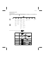
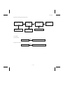
10) Comm. check mode
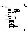
14) RS-232C check mode
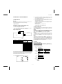
1 Turn on the line monitor.
2 Set 0 km at the line equivalence.
3 Bring the copy mode into the continuity mode.
4 It is set to shift into the diagnosis mode when the SPEED key
RS-232C interface board is checked.
When the interface board is installed, the result will be printed after
the check.
15) Dept. passcode
alone is pressed.
After the check, it is necessary to be sure to return the aforementioned soft switches into the initial state.
(Clear the memory with the diagnosis.)
The department passcode list is printed.
16) Conf. passcode
The confidential passcode list is printed.
Differing from printing of one box alone soon after registration, the
confidential passcodes of all boxes are printed.
11) Memory clear
Clear the back-up memory to initialize the soft switches.
The flash memory will be initialized. Then, the initialized list be output.
17) Print hold code
The print lockout passcode No. is printed.
12) Flash memory
The flash memory is checked.
The ordinary memories (ROM, SRAM, DRAM) are checked in the
ROM&RAM check process. The write/read test is taken every block to
print the result.
18) Memory set mode
The set and dump list of the memory content is output.
•
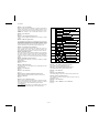
The address (8 digits (P) generally including the bank information
is input, and the data of 2 digits is continuously input.
Inputting is done in the hexadecimal mode. The ten-key is used for
0 thru 9, and the alphabetic keys A (RAPID01 thru 06) are used for
A thru F.
•
During data inputting, the address can be moved forward and
backward one byte by one byte with " " and "#". (The address
prior to the address 0 is looped as the maximum address.)
•
The Validity of the address is not checked. Accordingly, writing/reading operations are possible in the address of the memory
not assigned, the address of ROM and so on.
(However, as practical, writing is not done, and the data content
runs short each reading.)
Though writing is possible in the flash memory, a little time is
required.
It is also necessary to take care that the life of the flash memory is
excessively shortened if much data is written in the flash memory.
Since it may run away depending the written content, take minute
care for the writing address.
•
When the REPORT key is input, the memory dump list is produced
from the displayed address (here, it is limited at the 16-byte boundary address (address with end 0) which does not exceed the specified address and is just in front.). The dump list is output to a
maximum of 99 pages. If any data of one page can be repeatedly
developed and printed, the list is sufficient. But it is not desired that
the content of plural pages are developed in the memory once and
are then printed. If the STOP key is pressed, it will pass to the
diagnosis after the page which is now being printed is completed
printed.
If the address exceeds the maximum address, it will return to the
address 0 and printing will be continued.
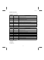
When an error occurs, the following error buzzer will sound.
Number of buzzer sounds
Check device
7 times <Short sounds>
Page memory
8 times <Short sounds>
Flash memory
9 times <Short sounds>
Flash memory (optional)
During operation of this diagnosis, dual operation is not possible at
all.
If this is excessively repeated, it will shorten the life of the flash
memory.
13) All FAX/TEL. entry mode
Before entry into the diagnosis, the reference destination number is
first written into the Rapid key number 01 in the FAX number registration mode.
1 The diagnosis mode is activated. If any number is not registered in
the Rapid key number 01 or any program or group is registered,
the diagnosis will be passed without any execution.
2 The FAX/TEL number (including the substitutive one) of the Rapid
key number 01 is copied into the Rapid key numbers 02 thru 48.
3 The FAX number of the Rapid key number 01 is copied into the
speed key numbers 001 thru 150.
4 If any chain dial is not set in the Rapid key number 01, the Rapid
key numbers 02 thru 48 and speed key numbers 001 thru 150 are
registered in the group number.
If any chain dial is set, any group will not be produced but the
chain dial setting alone of the Rapid dial will be canceled.
(In all other Rapid key numbers except 01, the chain dial is kept
as it is set.)
(16th and subsequential letters of the destination name registered in
the Rapid No. 01 will be discarded.)
2–5