1
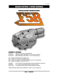
over view
TM
FEATURES
DD6 transmission Builders kit
The BAKER DD6 transmission Builders Kit comes with the necessary components
to change your stock 5-Speed into a 6-Speed, providing smoother shifting, positive
neutral-finding, and reduced cruising RPM on the highway as compared to the
stock 5-speed. With proven technology and helical 4th, 5th, and 6th gears, your
highway cruising is noise-free.
APPLICATION AND REQUIRED HARDWARE:
A Builder’s Kit is, as the name implies, for building a BAKER DD6 transmission
using an existing case housing and its peripheral hardware. The following 5-speed
components are required to complete this installation:
□ Transmission case
□ Pawl and sprocket spacer seals
□ Top cover and fasteners
□ Clutch release cover & fasteners
□ Clutch release mechanism and push rod hardware
PAGE | OVERVIEW
b aker dd6 i nstallatio n instr uct io ns:
V.4
table of contents:
3.
DD6 Builders Kit: Included Parts
4.
DD6 Builders Kit: Included Parts Detail
5.
DD6 Exploded View Diagrams
9.
Skills, Tools, and Knowledge
10
DD6 Builders Kit Assembly: Prep, Checks, Gear installation
11. DD6 Builders Kit Assembly: Gear installation continued
12. DD6 Builders Kit Assembly: Forks, Checks, Drum
13. DD6 Builders Kit Assembly: Shifter pawl, neutral switch installation
14
DD6 Builders Kit Assembly: Primary chain and sprocket
15. DD6 Builders Kit Assembly: speedo sensor and fluids
16. Terms
17. Disclaimer
PAGE 2 | TABLE OF CONTENTS
iNCLUDeD PArT S
PArTS ProviDeD wiTH THe bAker DD6 bUiLDerS kiT
4
2
1
8
3
6
7
5
THe FoLLowiNG PArTS Are iNCLUDeD AS SHowN iN FiGUre .
1. Assembled DD6 gear set on BAKER bearing door.
2. Shift drum with redundant neutral pillow blocks.
3. shifter pawl, model specific.
4. New P/n: 6209 main bearing and beveled snap ring.
5. Three shift forks, labeled #2, #3, and #4.
6. Bearing grade fork rod.
7. 28t Compensating sprocket and chain, model specific.
8. Primary shaft Race
oTHer PArTS iNCLUDeD (NoT SHowN iN FiGUre ).
9. Neutral switch (some models).
10. Replacement chain tensioner pad and hardware (some models).
11. Eccentric adjuster screw
12. Seal 12067B
PAGe 3 | PArTS
b a k e r D D 6 ™ Bui lder s K it includ ed parts De ta i l
DD6
Gearset
p\n:
401(2.94 1st)
or
411(3.24 1st)
Gasket set
p\n’s:
36801-87b
shift drum
p\n:
124d-dd6
fork rod
p\n:
122-6
(side cover)
35652-79b
(trap door
cover)
34904-86c
(top cover)
shift forks
p\n’s:
172-DD6
173-dd6
174-dd6
sprocket
p\n:
158-56
PAGE | parts included details
Primary race
p\n:
34091-85x
main bearing
p\n:
6209
shifter pawl
p\n:
555-56a
or
555-56l
ex pl od e d view diag r am s
SHIFT SYSTEM
SHIFT
SYSTEM
VIEW 1
1
2
3
4
5
9
6
10
14 13
8
12
11
7
15
18
Number Part Number
1
23207
2
33001
3
124E-DD6-A
4
609B
5
122-6
6
172-DD6
7
173B-DD6
8
174-DD6
9
555-56A
10
33715-85S
11
31F100KCSS/P
12
70813
13
152-56A
14
25702
15
68010
16
6497HW
17
12045
18
33114-79A
17
Descriptionqty
1/4-20 x 1 1/4 SHCS Plain 4
3/16 washer, plain 4
Shift System, DD6
1
Alignment pin 5/16x3/8
4
Fork Rod, 6-speed BAKER
1
Fork, 2nd MS
1
Fork, 3rd C/S
1
Fork, 4-5 MS
1
Ratchet Pawl, anti overshift Rev. A 1
Shift Lever, stainless steel
1
5/16-24 x 1 SHCS Polished 1
7/16-14 Jamnut stainless steel
1
Eccentric Adjuster
1
1/2-20x1/2 SET SCREW
1
7/1 6” ext snap ring 1
washer, shift shaft 1
Seal Shift Lever 1
Bushing, Shifter Pawl
1
PAGE | exploded view diagrams
16
ex pl oded view di ag r ams
GEARSET
GEAR
VIEW 2
2
3
7
1
2
4
6
SET
5
8
9
8
8
6
5
10
5
6
11
12
13(A)
12
1
2
3
4
5
6
7
8
9
10
11
12
13
13A
14
14A
PN
Description
12035BOil Seal, Maindrive
HK2520
Bearing, 6th maindrive assembly
DD6-6M-1
BAKER DD6 6th MN
DD6-2M-1
BAKER DD6 2nd MN 11067
Retaining Ring
6003B
Thrust Washer
DD6-3M-1
BAKER DD6 3rd MN
8876A
Cage Bearing
DD6-4M-1
BAKER DD6 4th MN
DD6-4C5-1
BAKER DD6 4-5 clutch gear
DD6-5M-1
BAKER DD6 5th MN
TWD1423
Thrust Washer DD6-MS-2.94
BAKER DD6 mainshaft (2.94 1st stock)
DD6-MS
BAKER DD6 mainshaft (3.24 1st optional)
DD6-CS
BAKER DD6, CS CLUSTER (2.94 1st stock)
DD6-CS
BAKER DD6, CS CLUSTER (3.24 1st optional)
PAGE | exploded view diagrams
14(A)
QTY
1
2
1
1
5
5
1
5
1
1
1
2
1
1
1
1
PAGE | exploded view diagrams
25
20
32
19
2
3
31
3
18
16
27
26
30
7
17
24
29
15
28
11
10
22
21
14
12 11
33
9
34
35
8
36
4
3
37
2
42 41
7
TRANSMISSION HOUSING
40
1
39
5
6
23
38
13
ex pl oded view di ag r ams
TRANSMISSION HOUSING
VIEW 3
ex pl od e d view diag r am s
THE FOLLOWING PARTS ARE INCLUDING AS SHOWN IN
TRANSMISSION HOUSING
VIEW 3
NUMBER PN
1
25C225KCSS/P
2
25C125KCSS/P
3
6099SS
4
33902-98
5
34468-56A 6
34904-86E
7
609B
8
214C-56CB
9
26770
10
37089-84
11
TWC411
12
TC411
13
37088-90
14
10705-01149
15
66853
16
124-5L38
17
459-6
18
45-9404
19
25C225KCSS/P
20
25C125KCSS/P
21
130-56BSP
22
66825
23
1302-334PP
24
36801-87B
25
24050
26
37141
27
6304
28
6100
29
31C125KCSS/P
30
133-DD6
31
23202
32
51740-001
33
132A-DD6-E
34
35652-79B
35
F1409
36
23205
37
11733A
38
BK2526
39
12067B
40
33344-94S
41
11165A
42
6209
Description
QTY 1/4-20 x 2 1/4” SHCS polished SS
1
1/4-20 x 1 1/4” SHCS polished SS
6
Washer, Stainless Steel, 13
Switch, Neutral Indicator 1
Top Cover, LSD 91-98 ST 1
Gasket, Top Cover, forged
1
alignment dowel
4
BAKER trans housing, 1
dowel, starter
1
Cltuch Rod 5spd. 1
thrust washer, throw out
2
Bearing clutch rod roller
1
Clutch Rod 1
C-Clip
1
o-ring, -216
2
piston, 1.375 bore
1
Chrome Hydr Clutch Cover, Indian
1
bleeder valve
1
1/4-20 x 2 1/4” SHCS polished SS
2
1/4-20 x 1 1/4” SHCS polished SS
4
Dipstick
1
o-ring, dip stick
1
3 11/32 internal snap ring, beveled
1
Gasket, Right Side Cover
1
1/4-20x5/8 BHCS, bearing retainer plate1
3/4-16 Jamnut
2
Bearing, trap door
2
5/16 washer 4
5/16-18 x 1 1/4 polished SS, SHCS
4
bearing retaining plate
1
1/4-20x5/8 SHCS, bearing retainer plate5
3/8-24 drain plug
1
Bearing Door, w/ear, indian logo
1
Gasket, Bearing Retainer
1
Door Magnet
1
1/4-20 x 1 SHCS
1
Stud, Rigid transmission
5
Bearing, C/S -Case
1
Main Seal
1
Pulley Spacer
1
quad seal
1
Bearing, main drive gear 1
PAGE | exploded view diagrams
SkiLL S, kNowLeDGe & T ooL S
reQUireD reADiNG
Regardless of the skill level or experience of the installer of the Builder’s Kit, it is highly recommended that
a genuine H-D Motor Company® parts catalog and Factory service Manual be available for reference on
the installation. The installation instructions for the BAKER DD6 will make reference to the Factory Service
Manual. Any Factory manual from 1990 to present will be sufficient.
SPeCiAL TooLS
The only special tools required are the same tools that would be required for any 5-speed installation. For
a list of other required tools, please consult your Factory service Manual.
For removing and installing of the main drive gear and
main drive bearing, BAKER DRIVETRAIN part number
ToolA-56 is required; an equivalent tool is also available
from your local Harley® dealer, part number 35316A.
Tool A-56
Tool B-56
TooL C-56
For removing and installing the bearing inner race on the
transmission mainshaft, BAKER DRIVETRAIN part number TooLB-56 is necessary. Harley® also offers an equivalent tool, 34902A.
For removing and installing the 1-7/8 transmission pulley
nut, BAKER DRIVETRAIN part number ToolD-56 will be
needed. The Harley® part number is 94660-37A.
Tool D-56
PAGe 9 | SkiLLS, kNowLeDGe AND TooLS
b a ker dd6 t m b ui lders ki t assembly
CASE PREPARATION/ GEARSET REMOVAL
If the Builder’s Kit is replacing an existing 5-speed, refer to your Factory Service Manual section 7, Mainshaft/
Countershaft removal. Follow gearset removal procedure.
Next, refer to section 7, Main Drive Gear removal, and follow removal procedure. Be sure to clean the case
with Brake Cleaner or another suitable cleaner before continuing with installation.
If the Builder’s Kit is going into a new case, no preparation is needed.
CASE CLEARANCE CHECKS:
The BAKER DD6 hardware is designed to fit in stock H-D® transmission cases without modification to the
case or the six-speed components. Since most aftermarket cases are styled after the H-D® equivalent, the
hardware will fit into aftermarket cases as well. This applies in most situations, but there are exceptions.
The internal walls of the cases ‘float around’ occasionally in H-D® and aftermarket castings, this is not an
indication of poor quality, but rather, is inherent of the casting process. Be sure to check for any potential
interference before final installation of the gearset. Any necessary case modification can be done with a
die-grinder.
GEARSET INSTALLATION
Inspect this landing
Special note: 2000 - 06 88B Softail transmissions
have a noted shortcoming with the landing that
supports the P/N: 6209 bearing. This landing comes
from the factory with a very thin wall thickness and
cracks in the corner between the landing and the
P/N: 6209 bearing bore. Inspect carefully for this
situation.
1. Install the new main drive gear bearing provided,
O.E. P/N: 6209, NEVER install the bearing into the
case by applying pressure to the inner race of the
bearing - you will destroy the bearing and it may fail.
Install the new retaining ring with the bevel facing
out.
2. Remove the main drive gear from the BAKER
DD6 gearset/trap door assembly by simply sliding it
off the mainshaft. To install the main drive gear into
the transmission case use BAKER DRIVETRAIN
part number TOOLA-56 and follow the directions as
described in the Factory Service Manual.
figure 1
step 1: install the new
bearing
figure 2
step 2:
removing the
main drive gear.
figure 3
PAGE 10 | assembly
b a ker dd6 t m b ui lders ki t assembly
Step 3:
installing
the shifter
pawl and
snap ring.
All models require the changing of the eccentric
adjustment screw for proper shift pawl adjustment.
2000-06 Softails and all ‘01 - ‘06 FLT and ‘05 Dyna
models will require this change. The adjustment
screw and locking nut are provided in the Builder’s
Kit.
3. At this time it is necessary to install the provided
shifter pawl. The pawl included with the Builder’s
Kit is essential to the proper operation of the shift
mechanism. It was specifically designed to improve
fork shifting and operate in conjunction with the
new shift drum to provide ease and smoothness
of shifting. It will be necessary to replace the 7/16”
external snap ring and washer that retains the pawl
with the ones provided at this time.
figure 4
step 4.
hanging the
door gasket.
4. Hang the door gasket provided onto the case
dowel pins and carefully push it down to seat it
against the gasket surface.
5. Apply some WD-40 or equivalent lubricant to the
main drive gear seal and to the mainshaft (on the
portion adjacent to the splines). Install the gearset
by sliding the mainshaft through the main drive
gear and slowly pushing the gearset assembly until
the case dowel pins contact the dowel holes in the
side door. Be sure that the threads in the end of the
mainshaft do not contact the seal in the main drive
gear. If the shaft tears the seal, leakage will occur.
A rubber hammer is helpful to tap the bearing door
gently. WARNING: impacting the ends
figure 5
step 5: installing the gearset.
of the transmission shafts will
cause the door bearings to
fail.
6. Install the four 5/16-18 x 1-1/4 SHCS (socket head
cap screws) along with the washers in the lower
four holes in the bearing door. Use a small amount
of Blue thread locker on the end of the threads and
torque the bolts to 13-16 ft. lbs.(156-192 in.lbs.)
Install the two 1/4-20 x 1 1/14 with washers in the
same manner above the dowel pin holes and torque
them to 7-9 ft. lbs (84-108 in. lbs).
figure 6
step 6:
installing
the four
SHCS .
figure 7
PAGE 11| assembly
b a ker dd6 t m b ui lders ki t assembly
SHIFT FORK INSTALLATION
proper shift
fork alignment.
Figure 8 shows the proper placement of the shift
forks. Fork number 4 is placed on the shift clutch
between the 4th and 5th gears on the mainshaft.
It will be necessary to engage the 4th gear on
the mainshaft with the shift clutch. This will make
installing the number 4 fork easier. Fork number 3
is placed on the 3rd countershaft gear. Fork number
2 is placed on the 2nd mainshaft gear. To simplify
installation, slide the 2nd mainshaft gear into the
3rd gear on the mainshaft. This provides adequate
room to slide the fork into the fork groove. Install the
primary fork rod as you would in a stock 5-speed
transmission through the holes in the forks. Once
assembled, the shift system should appear as
shown in Figure 8.
figure 8
FUNCTION CHECK
The three forks should operate smoothly along
the bearing grade fork rod once installed. If
binding occurs, check for proper placement and/or
obstructions inhibiting the ease of fork movement.
At this time, apply a generous amount of WD-40 or
transmission oil to the forks and fork rod.
shift drum
SHIFT DRUM/DETENT SYSTEM
The shift drum and pillow block system of the
BAKER DD6 transmission was designed with low
friction and ease of operation in mind. Inside the
shift drum is a ball bearing that reduces friction. No
shimming or setup is required with the shift drum
and pillow block system. The right side pillow block
has another provision known as “redundant neutral
detent”. The “redundant neutral” feature of the drum
aids in finding neutral with less effort.
Install the shift drum assembly as detailed in Figure
10 making sure that the fork pins are properly riding
in the drum. Install the provide 1/4-20 x 1/1/4 SHCS
along with washers as you would with a stock drum.
Put a small amount of Blue threadlocker on the
ends of the bolts and torque them down in a circular
patter 7-9 ft. lbs. (84-108 in. lbs.).
PAGE 12 | assembly
figure 9
b a ker dd6 t m b ui lders ki t assembly
Shifter Pawl Adjustment
All models shifter pawl is adjusted in 3rd gear.
All kit’s will include a replacement eccentric
screw and jam nut for pawl adjustment. The
eccentric screw must be timed to the shifter
pawl so they move on the same axes. The
directions will be described as looking at the
bike from the left side. When you turn the
eccentric screw clockwise the shifter arm
should transverse to the rear of the bike.
When you turn the screw counterclockwise
the arm should move to the front of the bike.
If this is incorrect the eccentric is off 180
degrees, turn the eccentric ½ turn clockwise.
Now that the eccentric screw and shifter pawl
are timed correctly, put the transmission in
3rd gear.
figure 10
proper shifter pawl adjustment in 3rd gear
With the transmission in 3rd gear adjust the
pawl to have equal free play (do not force
against return springs) front to back on the
dowel pins. Tighten jam nut, now double
check shifter pawl adjustment, as seen in
Figure 11.
Reassemble the remaining components of the
transmission as you would any stock 5-speed
as detailed in the Factory Service Manual.
figure 11
NEUTRAL SWITCH
Depending on the year of the motorcycle,
it may be necessary to replace the neutral
switch. All ‘00 - ‘06 Softail models along with
the ‘01 - ‘06 FLT and ‘05 FXD models , with
a black body switch, require installation of
the neutral switch, silver body, provided for
proper neutral light function.
replacing the neutral switch
figure 12
PAGE 13 | ASSEMBLY
b a ker dd6 t m b ui lders ki t assembly
PRIMARY CHAIN AND
SPROCKET INSTALLATION
Provided as part of the DD6 Builder’s Kit is a 28
tooth compensating sprocket, primary chain, and
tensioner with hardware (with some kits), to be
assembled as shown in Figure 13.
Figure 14 displays the parts included in the kit, as
follows:
1. P/N: DD6-177 Adjuster Retaining Nut
2. P/N: 24091 3/8-16 - 7/8 Allen Cap Screw
3. P /N: DD6-178 Chain Adjuster Shoe
4. P/N: 39990-01 Chain Tensioner
Some bikes are equipped with the late style chain
tensioner, and only require a thicker shoe (P/N:
DD6-178). Other bikes will require the late model
Chain Tensioner (P/N: 39990-01) as well as using
the altered bolt and nut that we include in the kit
(See Figure 14 and Figure 17).
figure 13
3.
1.
2.
4.
On Some models you will have to clearance the
2 pedastals on the inner primary that the chain
inspection cover bolts to. In those application
situations you will have to heli-coil the outer primary
cover for the two bolts that you clearanced.
FIGURE 14
For most older applications you will be able to flip
the entire tensioner (Figure 16) upside down (Figure
2) and that will accomplish the difference required.
We do not recommend using “auto tensioners” from
any manufacturer with our DD6 Builders Kit.
FIGURE 15
FIGURE 16
FIGURE 17
PAGE 14 | ASSEMBLY
b a ker dd6 t m b ui lders ki t assembly
SPEED SENSOR INSTALLATION
Provided in the kit is a speed sensor spacer. Remove
the speedometer sensor from the transmission case
and place the spacer plate (paper gasket) under the
stock sensor. This is important to maintain proper
spacing to the 5th gear on the mainshaft. The gasket
is only .060 thick, so be careful not to over-torque it.
You may require a speed sensor signal conversion
box to correctly re-calibrate the speedo head. This
unit and is available from BAKER DRIVETRAIN,
part number 95E-56.
baker speed sensor signal
conversion box. part number
95e-56.
FLUID FILL
Fluid capacity is 20-24 fluid oz. of one of the following
recommended oils.
BAKER recommends using Spectro Heavy Duty 6
Speed Gear Lube - which we have included in your
DD6 kit, in a premeasured bottle.
One of the following oils can be used:
Spectro - 75W 140SPL
Bel Ray - 80W 90
Torco - 85W 140
AMSOIL - 75W 90
PAGE 15 | ASSEMBLY
baker drivetrain
recommends using
Spectro Heavy Duty
6 speed Gear lube.
included in your kit
is a premeasured
bottle for your
convenience.
term s
SPECIAL ORDERS
A minimum $500 deposit is required with all special orders. Special orders include unique case finishes, unique side door requests
(i.e.; wrinkle black door or no logo).
ALL OTHER ORDERS
Orders can be pre-paid using VISA, Mastercard or American Express.
Prices shown are F.O.B. Haslett, MI. BAKERTM provides free UPS ground shipping on all retail orders for complete transmissions or
transmission kit. UPS air shipment is available upon request. Customer is responsible for air shipment premiums.
LIMITED WARRANTY
BAKERTM Inc. transmission assemblies, transmission kits, and wide tire kits are guaranteed to the original purchaser to be free
of manufacturing defects in materials and workmanship for a period of 5 years from the date of purchase or up to 50,000 miles whichever is sooner.
If the product is found by BAKERTM to be defective, such products will, at the option of BAKERTM, be replaced or repaired at cost to
BAKERTM.
In the event warranty service is required, the original purchaser must call or write BAKERTM immediately with the problem.
If it is deemed necessary for BAKERTM to make an evaluation to determine whether the transmission assembly or transmission kit
is defective, the entire transmission assembly, whether originally purchased as an assembly or kit, must be properly packaged and
returned prepaid to BAKERTM with a copy of the original invoice of purchase.
If after an evaluation has been made by BAKERTM and a defect in materials and/or workmanship is found, BAKERTM will, at BAKER’s
option, repair or replace the defective part of the assembly.
Warranty card must be returned within 45 days of purchase to be valid.
ADDITIONAL WARRANTY PROVISIONS
This limited warranty does not cover labor or other costs or expenses incidental to the repair and or replacement of
BAKERTM products. This warranty does not apply if one or more of the following situations is judged by BAKERTM to be
relevant: improper installation, accident, modification (including but not limited to use of unauthorized parts), racing,
high performance application, mishandling, misapplication, neglect (including but not limited to improper maintenance),
or improper repair.
BAKERTM shall not be liable for any consequential or incidental damages arising out of or in connection with a BAKERTM
transmission assembly, transmission kit, swingarm, fender, component or part. Consequential damages shall include
without limitation, loss of use, income or profit, or losses sustained as the result of injury (including death) to any person
or loss of or damage to property.
BAKERTM transmissions, transmission kits, and Wide Tire Kits are designed exclusively for use in Harley-Davidson®
motorcycles. BAKERTM shall have no warranty or liability obligation if a BAKERTM part is used in any other application.
If it is determined that a BAKERTM transmission assembly has been disassembled during the warranty period for any
reason, this limited warranty will no longer apply.
PAGE 16 | TERMS
disclaimer
The words Harley, and H-D are registered trademarks and are for reference only. Use of H-D model designations and
part numbers are for reference only. BAKER Drivetrain has no association with, and makes no claim against, these
words, trademarks, or companies.
It is the sole responsibility of the user to determine the suitability of this product for his or her use, and the user
shall assume all legal, personal injury risk and liability and all other as well as all other obligations, duties and risks
associated therewith.
customer support
For any installation or service questions, please contact our BAKER technical department toll free: 1-877-640-2004.
PAGE 17 | DISCLAIMER
NO TEs
NO TEs
9804 E. SAGINAW
HASLETT, MI 48840
TOLL FREE: 1-877-640-2004