1
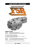
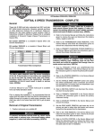
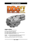
V4-3909
BAKER FRANKENTRANNY BUILDER’S KIT
BAKER Drivetrain’s 1999 Road King w/Part Numbers: FT106SL (Frankentranny Kit), 478-56CP-U84 (Kicker
Cover), 3511-64 (Kick Arm/Pedal Assembly, 475-56P (Oil Spout Assembly), and 5011(Gates Ignition Kit)
P/N:
FT106P
FT106L
FT106SL
(FRANKENTRANNY BUILDERS KIT; 01-06 FL / 01-05 DYNA® / 00-06 SOFTAIL®)
(FRANKENTRANNY BUILDERS KIT; 90-97 BIG TWIN MOTORCYCLES)
(FRANKENTRANNY BUILDERS KIT; 98-99 SOFTAIL® / 98-00 FL, DYNA®)
PAGE 1 - COVER
V4-3909
BAKER FRANKENTRANNY KIT OVERVIEW
FEATURES
The Frankentranny Builders Kit effectively converts a factory 5-Speed into a 6-Speed overdrive
with provisions for a 1936-based 4-Speed kicker. Why did we do this? Because a timeless kicker
on a Big Twin looks really cool! And kick starting your bike in a crowd of button pushers is boner
material.
FITMENT
•
1990-2006 Big Twin Motorcycles (except 2006 Dyna®)
TOOLS, RESOURCES, REQUIRED PARTS
•
Touring Models Must Use A True Dual Exhaust System For Proper Fitment
•
Factory Service Manual For Your Motorcycle
•
Factory Parts Manual For Your Motorcycle
•
Common Hand Tools (allens, sockets, hammer / chisel)
•
Die Grinder or Files (if transmission case needs to be modified)
•
Torque Wrench (with ft. lbs. and in. lbs.)
•
Blue Loctite® (242 Removable) or Equivalent
•
Red Loctite® (271 Permanent) or Equivalent
•
Feeler gauges
•
Main Drive Gear & Bearing Service Tools
o BAKER P/N ToolA-56
o H-D® Equivalent P/N 35316A
•
Pulley Nut Socket
o BAKER P/N TOOLD-56
o H-D® Equivalent P/N 94660-37B
•
Inner Primary Race Service Tool
o BAKER P/N TOOLB-56
o H-D® Equivalent P/N 34902A
PARTS REQUIRED TO COMPLETE BUILD
•
Kicker Cover Kit w/Kicker Gears, See Page 14.
•
Kicker Arm w/Pedal, See Page 14.
•
Ignition Retrofit Required On Twin Cam Models, See Page 14.
•
Fuel Injected Motorcycles Must Be Converted To Carburetor.
•
1993-2006 Touring Models Require A BAKER Oil Spout. The Bulky Stock Spout Interferes
With The Frankentranny Bearing Door, See Page 14.
•
Touring Models Must Use A True Dual Exhaust System For Proper Fitment.
BAKER HIGHLY RECOMMENDS THAT OUR TRANSMISSION BUILDER’S
KIT’S BE INSTALLED ONLY BY A TRAINED AND OR SEASONED MECHANIC
WITH PRIOR H-D® TRANSMISSION EXPERIENCE. IF YOU HAVE NEVER
SERVICED AN H-D® TRANSMISSION; DO NOT ATTEMPT INSTALLING THIS
BUILDERS KIT.
PAGE 2 - OVERVIEW
V4-3909
BAKER FRANKENTRANNY BUILDER’S KIT
TABLE OF CONTENTS:
2) Overview
3) Table Of Contents
4) Included Parts Breakdown
5) Included Parts Breakdown Legend
6) Included Parts Breakdown w/Legend
7) Included Parts Breakdown w/Legend
8) Disassembly, Case Preparation
9) Case Preparation Continued
10) Case Preparation Continued, Gearset Installation
11) Gearsest Installation Continued, Shift Fork Installation
12) Shift Fork Installation Continued, Shift System Installation
13) Shift System Installation Continued, Finish Line
14) Notes
15) Terms
16) Disclaimer
PAGE 3 - TABLE OF CONTENTS
V4-3909
BAKER FRANKENTRANNY EXPLODED VIEW
INCLUDED PARTS DETAIL
FIGURE 1
PAGE 4 - INCLUDED PARTS DETAIL LEGEND
V4-3909
BAKER FRANKENTRANNY EXPLODED VIEW
INCLUDED PARTS DETAIL LEGEND
ITEM
QTY
P/N
DESCRIPTION
1
1
10705-01149
C-Clip, Actuator Rod
2
2
TWC411
Ground Washer, Actuator Rod
3
1
TC411
Thrust Washer, Actuator Rod
4
1
125-5R
Actuator Rod
5
1
6N4-SIDE
Gasket, Side Cover
6
1
35652-79B
Gasket, Bearing Door
7
4
33001
Washer, Shift System
8
4
23207
1/4-20 x 1.250” SHCS
9
1
10
2
98-620GA
.020” Shim, Shift System
11
1
98-625GA
.025” Shim, Shift System
12
1
34904-86E
Gasket, Top Cover
13
1
37088-90E
Rod, Clutch Release
14
1
73753
1/4-20 x .625” BHCS
15
1
108-6EP
Speedo Plug
16
1
66808
O-Ring, Buna #014
17
4
6099SS
Washer, 1/4”
18
4
25C125KCSS/P
1/4-20 x 1.250” SHCS S.S.P.
19
4
6100
Washer, 5/16”
20
4
31C150KCSS/P
5/16-18 x 1.500” SHCS S.S.P.
21
1
See Figure 2
Door / Gearset Assembly
22
1
102-6E
4th Gear Countershaft Fork
23
1
101-6E
1st Gear Mainshaft Fork
24
1
102-6F
3rd Gear Countershaft Fork
25
1
101-56E
2nd Gear Mainshaft Fork
26
1
122-64
Fork Rod (6.250” Length)
27
1
25702
1/2-20 X .500” Fork Rod Plug
28
1
6209
Bearing, Main Drive Gear
29
1
1302-334PP
Beveled Snap Ring
30
1
12067B
Seal, Main Drive Gear
31
1
11165A
Quad Seal
32
1
33344-94S
Spacer, Pulley
33
1
34091-85
Inner Bearing Race
4-6QEN / 5-6 QSN / 5-6 QLN
Shift System
PAGE 5 - INCLUDED PARTS DETAIL LEGEND
V4-3909
BAKER FRANKENTRANNY EXPLODED VIEW
INCLUDED PARTS DETAIL
FIGURE 2
ITEM
QTY
P/N
DESCRIPTION
1
1
168-6N4
Nut, Mainshaft
2
1
WHM-200
2” Internal Spiral Lock
3
1
1640-DSTN
Bearing, Mainshaft
4
1
37141
3/4-16 Nylock Nut
5
2
24040
10-32 x 1.500” BHCS
6
1
51740-001
3/8-24 Zero Leak Drain Plug
7
1
204KG
Bearing, Countershaft
8
1
2-6F-P
Bearing Door
9
1
25287
10-32 x 2.000” Set Screw
10
1
112-6D
Auxiliary Fork Rod
11
1
115-6E
Support Bridge
12
1
TRB-1423
Shim, Mainshaft
13
1
See Figure 3
Gearset Assembly
14
2
HK2520
Bearing, Main Drive Gear
15
1
61005M
Main Drive Gear
16
1
12035B
Seal, Main Drive Gear
PAGE 6 - INCLUDED PARTS DETAIL
V4-3909
BAKER FRANKENTRANNY EXPLODED VIEW
INCLUDED PARTS DETAIL
FIGURE 3
ITEM
QTY
P/N
DESCRIPTION
1
5
8876A
Bearing, Gearset
2
1
60866M
6th Gear, Mainshaft
3
7
6003B
Thrust Washer, Gearset
4
6
11067A
Retaining Ring, Gearset
5
1
62941M
1st Gear, Mainshaft
6
1
61234M
4th Gear, Mainshaft
7
2
603M2C
8
1
62212M
2nd Gear, Mainshaft
9
1
996041-8
Mainshaft, Kicker Style
10
1
60866C
Countershaft, 6th Gear
11
1
61005C
5th Gear, Countershaft
12
1
61573C
3rd Gear, Countershaft
13
1
61234C
4th Gear, Countershaft
14
1
62941C
1st Gear, Countershaft
`
3rd Gear Mainshaft / 2nd Gear Countershaft
PAGE 7 - INCLUDED PARTS DETAIL
V4-3909
BAKER FRANKENTRANNY BUILDER’S KIT
DISSASSEMBLY
1) FOR YOUR SAFETY, DISCONNECT BOTH BATTERY CABLES (FAILURE TO DUE SO
COULD RESULT IN PERSONAL INJURY).
2) With your bike securely supported on a bike lift or jack, drain the transmission fluid. Refer to
your Factory Service Manual for location of your drain plug.
3) Refer to your Factory Service Manual for transmission gearset, main drive gear, and main
drive gear bearing removal.
4) Remove your transmission speed sensor from the transmission case.
CASE PREPERATION
The BAKER FrankenTranny Builder Kit hardware is designed to fit in a stock H-D® and
aftermarket transmission cases without modification to the case or Six-Speed components, but
there are exceptions. The internal walls of transmission cases float around occasionally, this is
not a quality problem, but rather is inherent in the casting process. With that in mind the following
steps are a number of checks to make sure that your new builders kit will function and perform
flawlessly.
IT IS CRITICAL THAT BEFORE YOU DO ANY MODIFICATION TO YOUR
TRANSMISSION CASE THAT YOU THROUGHLY CLEAN OUT THE CASE
WITH BRAKE CLEANER OR LACQUER THINNER IN A WELL VENTILATED
AREA, DRY OUT, THEN TAPE OFF THE COUNTER SHAFT BEARING WITH DUCT
TAPE TO PREVENT ANY DEBRIS FROM ENTERING THE BEARING AS YOU WILL
NOT BE REPLACING IT. IF YOU NOTICE THAT THE BEARING IS DAMAGED IN
ANYWAY PLEASE REFER TO YOUR FACTORY SERVICE MANUAL FOR REPLACING
THE BEARING. COUNTER SHAFT BEARING H-D® P/N 8977 OR BAKER P/N
BK2526.
1) Checking for 6th gear (P/N: 60866M) Mainshaft clearance.
A. Place the provided door gasket onto the transmission case. The gasket is going to act
like a template.
B. If the meat of the boss around the 5/16-18
screw hole and fork rod boss hole is above or
below the profile of the door gasket. Mark the
area with a black marker; from roughly the 10
o’clock to 2 o’clock position on the 5/16-18
screw hole boss and the 6 o’clock to 8 o’clock
position on the fork rod boss, shown in figure
4. If the meat of the boss is below or the same
as the profile of the door gasket proceed to
step 2.
C. After marking the area of concern in step 1B,
remove the door gasket, then remove the
SHOWN IN RED ARE THE AREAS OF CONCERN FIGURE 4
case material using a coarse flat file or die
grinder. Remove only the marked material
roughly a ½” back from the door gasket surface.
(CONTINUED ON NEXT PAGE)
PAGE 8 - DISSASSEMBLY / CASE PREP
V4-3909
BAKER FRANKENTRANNY BUILDER’S KIT
2) Checking for Auxiliary Fork Rod bridge clearance.
A. The auxiliary fork rod bridge comes installed on
the inside of the bearing door shown in figure 5.
The bridge functions as the support for the 4th
gear counter shaft fork.
B. Using the door gasket as a template again, as in
step 1A. If any transmission case material is
below the profile of the door gasket, mark with a
black marker see figure 6.
C. If case material is not below the gasket profile
proceed to step 3. Remove the marked material
with a coarse round file or die grinder. Remove
the material inward (perpendicular to gasket
surface) roughly 1-3/8” from the gasket
surface.
SHOWING AUXILIARY FORK ROD
FIGURE 5
3) Checking right side pillow block clearance.
A. Install the shift system on the transmission
case. Install the four 1/4-20 SHCS bolts with
washers; snug the bolts down evenly working
in a circular pattern until all four bolts are tight.
NEVER RUN ONE CAP SCREW ALL THE
WAY DOWN WITHOUT SEQENTIALLY
TIGHTENING THE
OTHER THREE AS SPECIFIED; IRREPARABLE
DAMAGE WILL RESULT.
SHOWN IN RED IS AREA OF CONCERN
FIGURE 6
CLEARANCE BETWEEN PILLOW BLOCK AND CASE
FIGURE 7
B. Any clearance greater than zero is acceptable,
figure 7.
C. If you are installing this builder’s kit into a
Delkron® Softail® case, install the shift system
onto the case and mark where the right side
pillow block hits. You will have to remove some
material as shown in figure 8 using a coarse file
or die grinder.
4) Checking top cover fitment.
A. If you are installing an aftermarket top
cover, you will have to check for proper fitment
around the shift system. Some grinding on the
casting webs might be necessary for correct
function of the shift drum. All checks should be
made with the shift system installed on the
transmission.
REMOVE MATERIAL
YOU MARKED IN STEP
3C
IF YOU HAVE A 2000-2006 SOFTAIL®, 20012005 DYNA®, OR A 2001-2006 FLT / FLH
YOU MUST MODIFIY YOUR STOCK SHIFTER
PAWL (RATCHET PAWL). AS SHOWN ON THE
NEXT PAGE.
SHOWN IS THE AREA OF CONCERN
(CONTINUED ON NEXT PAGE)
PAGE 9 - CASE PREP
FIGURE 8
V4-3909
BAKER FRANKENTRANNY BUILDER’S KIT
5) Shifter Pawl modification.
A. Proceed to gearset installation if the year and
model specified on page 9 does not match your
motorcycle.
B. Following the procedures in your Factory
Service Manual, remove the ratchet pawl from
the transmission case.
C. Remove the spring-loaded pawl from the arm to
gain clear access to the “beak” on the arm.
Using figures 9-10, remove the material as
shown with a bench grinder or D.A. Grinder.
D. Reassemble the ratchet pawl per your
FIGURE 9
FIGURE 10
Factory Service Manual into the
FIGURES SHOWING BEFORE AND AFTER PAWL MODIFICATION
transmission case.
GEARSET INSTALLATION
IT IS CRITICAL THAT THE TRANSMISSION CASE BE FREE OF DEBRIS AND
DIRT. USING BRAKE CLEANER OR LACQUER THINNER IN A WELL
VENTILATED AREA, CLEAN OUT THE TRANSMISSION CASE. ANY DEBRIS
LEFT IN CASE MIGHT CAUSE SEVERE DAMAGE TO THE GEARSET AND / OR
BEARINGS.
1) Install the provided main bearing (P/N: 6209) into the case with snap ring (P/N: 1302-334PP),
bevel side facing out. Refer to your Factory Service Manual for guidelines and proper tools
required.
SPECIAL NOTE – 2000-UP 88B SOFTAIL® TRANSMISSION CASES HAVE A
NOTED DEFECT TO THE LANDING
THAT SUPPORTS THE 8996A (MAIN
BEARING). THIS LANDING COMES STRAIGHT
FROM THE FACTORY WITH A VERY THIN
WALL THICKNESS AND CRACKS IN THE
CORNER BETWEEN THE LANDING AND THE
8996A
BEARING
BORE.
INSPECT
CAREFULLY FOR THIS SITUATION, FIGURE
11. WHEN INSTALLING THE NEW BEARING,
PRESS IT IN CAREFULLY AND DO NOT
CRACK THE LANDING OFF OF THE CASE. ARROW POINTING TO THE AREA OF CONCERN FIGURE 11
2) Remove the 5th main gear (P/N: 61005M) from the mainshaft on your new gearset by sliding it
off the end.
3) Install the 5th main gear into the transmission case referencing your Factory Service Manual for
guidelines and proper installation tools.
4) Install the bearing door gasket (P/N: 35652-79B) onto the transmission, making sure the
gasket is fully seated on the dowels and is against the case gasket surface.
5) Apply some WD40® or equivalent to the main drive gear seal and the mainshaft on the gearset
assembly. Install the gearset by sliding the mainshaft through the main drive gear and slowly
pushing the whole trap door / gearset assembly until the case dowels pins contact the dowel
holes in the bearing door.
(CONTINUED ON NEXT PAGE)
PAGE 10 - CASE PREP / GEARSET INSTALLATION
V4-3909
E.
BAKER FRANKENTRANNY BUILDER’S KIT
IT IS CRITICAL THAT YOU DO NOT
DRAG THE MAINSHAFT THREADS OR
SPLINES ACROSS THE MAIN GEAR
SEAL; THIS WILL CAUSE DAMAGE TO THE
SEAL CAUSING FUTURE LEAK ISSUES.
6) Using a rubber mallet tap the side of the bearing
door (area over the dowels) on each side slowly
walking in the trap door / gearset assembly until its
flush and up against the gasket. NEVER HAMMER ON
THE BEARINGS TO FULLY SEAT THE BEARING DOOR;
THIS WILL CAUSE BEARING FAILURE AND DAMAGE
SHOWING SPEED SENSOR INSTALLED
FIGURE 12
YOUR GEARSET.
7) Install the bottom four 5/16-18 SHCS and washers
with Blue Loctite®. Torque the four bottom bolts,
starting in the center and working your way out to the
sides to 16-18 ft-lbs (200-225 in-lbs).
8) Install the top four 1/4-20 SHCS and washers with
Blue Loctite®. Torque the four top bolts, starting in the
center and working your way out to the sides to 8-10
ft-lbs (100-120 in-lbs).
9) In your builders kit we supply a speed sensor plug
with O-ring and bolt; install the speed sensor plug on
your transmission case. Using WD40® on the O-Ring
AUXILIARY ROD ADJUSTER
FIGURE 13
®
will aid in installing the plug. Using Blue Loctite on the
stock speed sensor bolt torque to 8-10 ft-lbs (100-120
in-lbs).
10) Install your motorcycle speed sensor on the new
bearing door using the provided button head bolt with
Blue Loctite®, torque to 8-10 ft-lbs (100-120 in-lbs),
figure 12.
SHIFT FORK INSTALLATION
Reference the included parts, figure 1 on page 4 and
legend on page 5. You will notice that the 3rd (P/N
102-6F), 2nd (P/N 101-56E), and 1st (P/N 101-6E) gear
forks will ride on the primary fork rod (like your stock
5-Speed). The 4th (P/N 102-6E) gear fork will ride on
an auxiliary fork rod connected to the bearing door.
SHOWING 1ST GEAR ENGAGED
FIGURE 14
1) Using a 3/32” Allen, back out the auxiliary fork rod
turning it counter clockwise, until a little over 3/4" is
sticking out of the bearing door (past the side cover
gasket surface), figure 13.
2) Install the 1st (P/N 101-6E) gear mainshaft fork.
You must slide the 1st gear away from the bearing
door and engage the dog teeth of the adjacent gear
(4th) to allow room for the fork to slide into position
figure 14.
INSTALLING 4TH GEAR SHIFT FORK
(CONTINUED ON NEXT PAGE)
PAGE 11 - GEARSET INSTALLATION / FORK INSTALLATION
FIGURE 15
V4-3909
BAKER FRANKENTRANNY BUILDER’S KIT
3) Install the 4th (P/N 102-6E) gear shift fork onto the 4th (P/N 61234C) countershaft gear. While
holding the shift fork into position, screw back in the set screw for the auxiliary fork rod until it is
flush with the side cover gasket surface, figure 15.
4) Install the 3rd (P/N 102-6F) gear counter shaft and
2nd (101-56E) gear mainshaft forks, reference figure
1 and 16 for correct placement of shift forks.
5) If you did not remove the 1/2-20 fork rod set
screw from the left side of the case during removal
of your stock gearset due so now. Slide the provided
fork rod (P/N 122-64; 6.250” rod length) through the
primary side of the transmission making sure you go
through all shift forks; 1st mainshaft (P/N 101-6E), 3rd
countershaft (P/N 102-6F), and 2nd mainshaft (P/N
101-56E) forks.
6) Install the 1/2-20 fork rod set screw with Blue
Loctite®; thread into case until it bottoms out then
back off a 1/2 turn. Reinstall your transmission drain
plug.
7) Apply a generous amount of transmission oil to
the forks and fork rods. With all the forks installed,
check to make sure that all forks slide freely on the
fork rods by moving them back and forth. If you
experience any binding in the 4th gear counter shaft
fork, you need to go back and perform a clearance
check of the auxiliary fork rod / bridge; located in
step 2 of the case preparation.
4C FORK
3C FORK
2M FORK
1M FORK
SHIFT FORK PLACEMENT
INSTALLING DRUM SHIM
FIGURE 16
FIGURE 17
SHIFT SYSTEM INSTALLATION
The shift system comes with 3 shims (one .025”
thick and two .020” thick), start by installing the .020”
thick shim on the shifter pawl side of the drum,
shown in figure 17.
1) Install the shift system onto the transmission;
making sure to line up the fork pins with the grooves
in the shift drum.
2) Install the four 1/4-20 SHCS bolts with washers;
snug the bolts down evenly working in a circular
pattern until all four bolts are tight.
CHECKING DRUM END PLAY
FIGURE 18
NEVER RUN ONE CAP SCREW ALL THE WAY DOWN WITHOUT
SEQENTIALLY TIGHTENING THE OTHER THREE AS SPECIFIED;
IRREPARABLE DAMAGE WILL RESULT.
3) Check shift drum end play by using a feeler gauge as shown in figure 18. Shift drum end play
is .002” - .010”.
A. Place the feeler gage in between the shift drum shim and pillow block ; holding the drum
all the way toward the exhaust side. If the measurement is within the specification listed
above proceed to step 4.
(CONTINUED ON NEXT PAGE)
PAGE 12 - SHIFT FORK INSTALLATION / SHIFT SYSTEM
V4-3909
BAKER FRANKENTRANNY BUILDER’S KIT
B. If the measurement is greater then .010” remove the shift system and add one of the
other shims and reinstall the shift system as specified in step 2. Re-measure the drum
end play until the measurement is within the specification listed (.002”-.010”).
C. In the unlikely event that the drum end play is less than the lower limit of .002”; which
could be due to variation in your transmission housing or stack up of the BAKER
components, give us a call toll free @ 1-877-640-2004. Please have a set of vernier
calipers available to take measurements during your conversation to assist us with
diagnosis over the phone. If we determine that the issue lies with your transmission
case, we will assist you on how to remedy the problem. If the issue lies with our BAKER
components we will ship overnight the replacement hardware necessary to remedy the
problem.
4) Now that the shift drum end play is set; remove
the four bolts and apply Blue Loctite® re-install bolts
with washers. Snug down as specified in step 2 and
then torque to 8-10 ft-lbs (100-120 in-lbs).
5) Set the shifter pawl adjustment per your Factory
Service Manual found in section 7 under, Shifter
Linkage Adjustment. Adjustment should be made in
3rd gear; measurement must be equal to within .010”
between pins, see figure 19. Shift through all gears
while spinning the mainshaft to make sure
everything is functioning correctly.
6) Install the top cover gasket and top cover with
bolts referring to your Factory Service Manual.
SHIFTER PAWL PIN ADJUSTMENT
FIGURE 19
FINISH LINE
1) Install the supplied inner bearing race onto the mainshaft, P/N 34091-85 following your Factory
Service Manual and using the Inner Primary Race Service Tool BAKER P/N TOOLB-56 or H-D®
Equivalent P/N 34902A. An optional BAKER High Torque Bearing Kit is available P/N 189-56.
The BAKER High Torque Bearing Kit replaces the factory roller bearing and race with a precision
honed ball bearing and seal. This will eliminate the possibility of the race moving and potentially
causing leaks or damage to the transmission.
2) Install the provided clutch release and actuator rod into the mainshaft.
3) Re-install all primary components, rear belt, sprocket or pulley; that you removed to
disassemble the transmission following your Factory Service Manual.
4) Install the kicker cover of your choice, and it’s components per the manufacturer’s instruction
sheets.
5) Install your exhaust and double check that all fasteners are tight on the motorcycle and any
ancillary parts that you removed to perform this installation are back in their intended place on the
motorcycle.
6) Fill the transmission with fluid. The BAKER Frankentranny Builders Kit comes with its own 23
fl-oz bottle of Heavy Duty Platinum Spectro® Transmission Fluid.
Once the maiden voyage had been made around the block or down the road. Take the time to
double check all fasteners and hydraulic fittings for tightness. Also with the bike as close to level
as you can safely get it and the transmission fluid warmed up, double check the level of the fluid.
Drain off any excess fluid if the transmission is overly full. Level should be at the bottom of the
hole. Re-install the oil level plug with; snug. You are complete….
PAGE 13 - SHIFT SYSTEM / FINISH LINE
V4-3909
BAKER FRANKENTRANNY BUILDER’S KIT
BAKER OFFERS THE FOLLOWING ANCILLARY PRODUCTS FOR THE FRANKENTRANNY
BUILDER’S KIT:
P/N
478-56HP-U84
DESCRIPTION
Kicker cover with polished finish, hydraulic type including Klassic Kicker
Gears & 1.5” piston. Requires an H-D master cylinder or applicable
aftermarket unit with 11/16” piston diameter. Hydraulic clutch actuation is
the aesthetically cleanest setup because hydraulic line can be easily
hidden.
478-56CP-U84
Kicker cover with polished finish, cable type including Klassic Kicker
Gears and actuator ball ramps. As shown on front of these instructions.
Compatible with 1990-2006 stock clutch cables and is the easiest to
install and most economical clutch actuation setup.
479-56P-U84
Function Formed Hydraulic Kicker Cover with polished finish, including
Klassic Kicker Gears & 1.5” Piston. Requires an H-D master cylinder or
applicable aftermarket unit with 11/16” piston diameter. Hydraulic clutch
actuation is the aesthetically cleanest setup because hydraulic line can
be easily hidden.
3510-64P
Kick arm assembly, straight design, polished stainless steel, with bronze
pedal
3511-64P
Kick arm assembly, straight design, +1” length, polished stainless steel,
w/ bronze pedal
474-56C-E
Oil spout assembly, FF type, chrome, 1993-99 FL
474-56P-E
Oil spout assembly, FF type, polished, 1993-99 FL
474-56C-T
Oil spout assembly, FF type, chrome, 2000-01 FL
474-56P-T
Oil spout assembly, FF type, polished, 2000-01 FL
475-56C
Oil spout assembly, FF type, chrome, 2002-06 FL, includes polished
stainless steel breather line
475-56P
Oil spout assembly, FF type, polished, 2002-06 FL, includes polished
stainless steel breather line
FOR TWIN CAM MODELS, ONE OF THE FOLLOWING IGNITION RETROFIT CHOICES IS
REQUIRED FOR FUNCTIONAL KICKER OPERATION.
P/N
T5
3757
DESCRIPTION
Morris Magneto nose cone assembly, polished. Fits 1999-2006 TC88A
& 2000-06 TC88B
* Specify gear or chain cam drive system when ordering to get the
correct worm drive gearset.
Vulcan Ignition conversion kit for chain cams, chrome. Fits 1999-05
Dyna, 1999-06 FL & Softail
3886
Vulcan Ignition conversion kit for gear cams, chrome. Fits 1999-05 Dyna,
1999-06 FL & Softail
4365
Vulcan Ignition conversion kit for chain cams, chrome. Fits 2006-up
Dyna, 2007-up FL & Softail
* Includes ignition module.
Gates Ignition conversion kit, polished. Fits 1999-05 Dyna, 1999-06 FL &
Softail
5011
* Specify gear or chain cam drive system when ordering; does not
include ignition module but utilizes any EVO era nose cone mounted
module.
PAGE 14 – PARTS REQUIRED TO COMPLETE YOUR BUILD
V4-3909
BAKER
BAKER
FRANKENTRANNY
BILLET KICKER
BUILDER’S
COVER KIT
SPECIAL ORDERS
A minimum $500 deposit is required with all special orders. Special orders include unique case finishes, unique side door
requests (i.e.; wrinkle black door or no logo).
ALL OTHER ORDERS
Orders can be pre-paid using VISA, MasterCard or American Express.
Prices shown are F.O.B. Haslett, MI. BAKER™ provides free UPS ground shipping on all retail orders for complete
transmissions or transmission kit. UPS air shipment is available upon request. Customer is responsible for air shipment
premiums.
LIMITED WARRANTY
BAKER™ Inc. transmission assemblies, transmission kits, and wide tire kits are guaranteed to the original purchaser to be
free of manufacturing defects in materials and workmanship for a period of 5 years from the date of purchase or up to
50,000 miles - whichever is sooner.
If the product is found by BAKER™ to be defective, such products will, at the option of BAKER™, be replaced or repaired
at cost to BAKER™.
In the event warranty service is required, the original purchaser must call or write BAKER™ immediately with the problem.
If it is deemed necessary for BAKER™ to make an evaluation to determine whether the transmission assembly or
transmission kit is defective, the entire transmission assembly, whether originally purchased as an assembly or kit, must
be properly packaged and returned prepaid to BAKER™ with a copy of the original invoice of purchase.
If after an evaluation has been made by BAKER™ and a defect in materials and/or workmanship is found, BAKER™ will,
at BAKER™ option, repair or replace the defective part of the assembly.
Warranty card must be returned within 45 days of purchase to be valid.
ADDITIONAL WARRANTY PROVISIONS
This limited warranty does not cover labor or other costs or expenses incidental to the repair and or replacement of
BAKER™ products. This warranty does not apply if one or more of the following situations is judged by BAKER™ to be
relevant: improper installation, accident, modification (including but not limited to use of unauthorized parts), racing, high
performance application, mishandling, misapplication, neglect (including but not limited to improper maintenance), or
improper repair.
BAKER™ shall not be liable for any consequential or incidental damages arising out of or in connection with a BAKER™
transmission assembly, transmission kit, swingarm, fender, component or part. Consequential damages shall include
without limitation, loss of use, income or profit, or losses sustained as the result of injury (including death) to any person or
loss of or damage to property.
BAKER™ transmissions, transmission kits, and Wide Tire Kits are designed exclusively for use in Harley-Davidson®
motorcycles. BAKER™ shall have no warranty or liability obligation if a BAKER™ part is used in any other application.
If it is determined that a BAKER™ transmission assembly has been disassembled during the warranty period for any
reason, this limited warranty will no longer apply.
PAGE 15 - TERMS
V4-3909
BAKER FRANKENTRANNY BUILDER’S KIT
The words Harley and H-D are registered trademarks and are for reference only. Use of H-D model designations and part
numbers are for reference only. BAKER Drivetrain has no association with, and makes no claim against, these words,
trademarks, or companies.
It is the sole responsibility of the user to determine the suitability of this product for his or her use, and the user shall
assume all legal, personal injury risk and liability and all other as well as all other obligations, duties and risks associated
therewith.
CUSTOMER SUPPORT
For any installation or service questions, please contact our BAKER technical department toll free: 1-877-640-2004.
PAGE 16 - DISCLAIMER