1
Fujitsu M10-1/SPARC M10-1
Service Manual
Manual Code: C120-E681-08EN
November 2014
Copyright © 2007, 2014, Fujitsu Limited. All rights reserved.
Oracle and/or its affiliates provided technical input and review on portions of this material.
Oracle and/or its affiliates and Fujitsu Limited each own or control intellectual property rights relating to products and technology described in this document, and such products,
technology and this document are protected by copyright laws, patents, and other intellectual property laws and international treaties.
This document and the product and technology to which it pertains are distributed under licenses restricting their use, copying, distribution, and decompilation. No part of such
product or technology, or of this document, may be reproduced in any form by any means without prior written authorization of Oracle and/or its affiliates and Fujitsu Limited, and
their applicable licensors, if any. The furnishings of this document to you does not give you any rights or licenses, express or implied, with respect to the product or technology to
which it pertains, and this document does not contain or represent any commitment of any kind on the part of Oracle or Fujitsu Limited or any affiliate of either of them.
This document and the product and technology described in this document may incorporate third-party intellectual property copyrighted by and/or licensed from the suppliers to
Oracle and/or its affiliates and Fujitsu Limited, including software and font technology.
Per the terms of the GPL or LGPL, a copy of the source code governed by the GPL or LGPL, as applicable, is available upon request by the End User. Please contact Oracle and/or its
affiliates or Fujitsu Limited. This distribution may include materials developed by third parties. Parts of the product may be derived from Berkeley BSD systems, licensed from the
University of California.
UNIX is a registered trademark of The Open Group.
Oracle and Java are registered trademarks of Oracle and/or its affiliates.
Fujitsu and the Fujitsu logo are registered trademarks of Fujitsu Limited.
SPARC Enterprise, SPARC64, SPARC64 logo and all SPARC trademarks are trademarks or registered trademarks of SPARC International, Inc. in the United States and other
countries and used under license.
Other names may be trademarks of their respective owners.
If this is software or related documentation that is delivered to the U.S. Government or anyone licensing it on behalf of the U.S. Government, the following notice is applicable:
U.S. GOVERNMENT END USERS: Oracle programs, including any operating system, integrated software, any programs installed on the hardware, and/or documentation, delivered
to U.S. Government end users are "commercial computer software" pursuant to the applicable Federal Acquisition Regulation and agency-specific supplemental regulations. As such,
use, duplication, disclosure, modification, and adaptation of the programs, including any operating system, integrated software, any programs installed on the hardware, and/or
documentation, shall be subject to license terms and license restrictions applicable to the programs. No other rights are granted to the U.S. Government.
Disclaimer: The only warranties granted by Oracle and Fujitsu Limited, and/or any affiliate in connection with this document or any product or technology described herein are those
expressly set forth in the license agreement pursuant to which the product or technology is provided.
EXCEPT AS EXPRESSLY SET FORTH IN SUCH AGREEMENT, ORACLE OR FUJITSU LIMITED, AND/OR THEIR AFFILIATES MAKE NO REPRESENTATIONS OR WARRANTIE
S OF ANY KIND (EXPRESS OR IMPLIED) REGARDING SUCH PRODUCT OR TECHNOLOGY OR THIS DOCUMENT, WHICH ARE ALL PROVIDED AS IS, AND ALL EXPRESS
OR IMPLIED CONDITIONS, REPRESENTATIONS AND WARRANTIES, INCLUDING WITHOUT LIMITATION ANY IMPLIED WARRANTY OF MERCHANTABILITY, FITNESS
FOR A PARTICULAR PURPOSE OR NONINFRINGEMENT, ARE DISCLAIMED, EXCEPT TO THE EXTENT THAT SUCH DISCLAIMERS ARE HELD TO BE LEGALLY INVALID.
Unless otherwise expressly set forth in such agreement, to the extent allowed by applicable law, in no event shall Oracle or Fujitsu Limited, and/or any of their affiliates have any
liability to any third party under any legal theory for any loss of revenues or profits, loss of use or data, or business interruptions, or for any indirect, special, incidental or
consequential damages, even if advised of the possibility of such damages.
DOCUMENTATION IS PROVIDED "AS IS" AND ALL EXPRESS OR IMPLIED CONDITIONS, REPRESENTATIONS AND WARRANTIES, INCLUDING ANY IMPLIED
WARRANTY OF MERCHANTABILITY, FITNESS FOR A PARTICULAR PURPOSE OR NON-INFRINGEMENT, ARE DISCLAIMED, EXCEPT TO THE EXTENT THAT SUCH
DISCLAIMERS ARE HELD TO BE LEGALLY INVALID.
Copyright © 2007, 2014, Fujitsu Limited. Tous droits réservés.
Oracle et/ou ses affiliés ont fourni et vérifié des données techniques de certaines parties de ce composant.
Oracle et/ou ses affiliés et Fujitsu Limited détiennent et contrôlent chacun des droits de propriété intellectuelle relatifs aux produits et technologies décrits dans ce document. De
même, ces produits, technologies et ce document sont protégés par des lois sur le droit d’auteur, des brevets, et d'autres lois sur la propriété intellectuelle et des traités internationaux.
Ce document, le produit et les technologies afférents sont exclusivement distribués avec des licences qui en restreignent l'utilisation, la copie, la distribution et la décompilation.
Aucune partie de ce produit, de ces technologies ou de ce document ne peut être reproduite sous quelque forme que ce soit, par quelque moyen que ce soit, sans l'autorisation écrite
préalable d'Oracle et/ou ses affiliés et de Fujitsu Limited, et de leurs éventuels concédants de licence. Ce document, bien qu'il vous ait été fourni, ne vous confère aucun droit et
aucune licence, exprès ou tacites, concernant le produit ou la technologie auxquels il se rapporte. Par ailleurs, il ne contient ni ne représente aucun engagement, de quelque type que
ce soit, de la part d'Oracle ou de Fujitsu Limited, ou des sociétés affiliées de l'une ou l'autre entité.
Ce document, ainsi que les produits et technologies qu'il décrit, peuvent inclure des droits de propriété intellectuelle de parties tierces protégés par le droit d’auteur et/ou cédés sous
licence par des fournisseurs à Oracle et/ou ses sociétés affiliées et Fujitsu Limited, y compris des logiciels et des technologies relatives aux polices de caractères.
Conformément aux conditions de la licence GPL ou LGPL, une copie du code source régi par la licence GPL ou LGPL, selon le cas, est disponible sur demande par l'Utilisateur Final.
Veuillez contacter Oracle et/ou ses affiliés ou Fujitsu Limited. Cette distribution peut comprendre des composants développés par des parties tierces. Des parties de ce produit
pourront être dérivées des systèmes Berkeley BSD licenciés par l'Université de Californie.
UNIX est une marque déposée de The OpenGroup.
Oracle et Java sont des marques déposées d'Oracle Corporation et/ou de ses affiliés.
Fujitsu et le logo Fujitsu sont des marques déposées de Fujitsu Limited.
SPARC Enterprise, SPARC64, le logo SPARC64 et toutes les marques SPARC sont utilisées sous licence et sont des marques déposées de SPARC International, Inc., aux Etats-Unis et
dans d'autres pays.
Tout autre nom mentionné peut correspondre à des marques appartenant à leurs propriétaires respectifs.
Si ce logiciel, ou la documentation qui l'accompagne, est concédé sous licence au Gouvernement des Etats-Unis, ou à toute entité qui délivre la licence de ce logiciel ou l'utilise pour le
compte du Gouvernement des Etats-Unis, la notice suivante s'applique :
U.S. GOVERNMENT END USERS: Oracle programs, including any operating system, integrated software, any programs installed on the hardware, and/or documentation, delivered
to U.S. Government end users are "commercial computer software" pursuant to the applicable Federal Acquisition Regulation and agency-specific supplemental regulations. As such,
use, duplication, disclosure, modification, and adaptation of the programs, including any operating system, integrated software, any programs installed on the hardware, and/or
documentation, shall be subject to license terms and license restrictions applicable to the programs. No other rights are granted to the U.S. Government.
Avis de non-responsabilité : les seules garanties octroyées par Oracle et Fujitsu Limited et/ou toute société affiliée de l'une ou l'autre entité en rapport avec ce document ou tout
produit ou toute technologie décrits dans les présentes correspondent aux garanties expressément stipulées dans le contrat de licence régissant le produit ou la technologie fournis.
SAUF MENTION CONTRAIRE EXPRESSEMENT STIPULEE AU DIT CONTRAT, ORACLE OU FUJITSU LIMITED ET/OU LES SOCIETES AFFILIEES A L'UNE OU L'AUTRE
ENTITE DECLINENT TOUT ENGAGEMENT OU GARANTIE, QUELLE QU'EN SOIT LA NATURE (EXPRESSE OU IMPLICITE) CONCERNANT CE PRODUIT, CETTE
TECHNOLOGIE OU CE DOCUMENT, LESQUELS SONT FOURNIS EN L'ETAT. EN OUTRE, TOUTES LES CONDITIONS, DECLARATIONS ET GARANTIES EXPRESSES OU
TACITES, Y COMPRIS NOTAMMENT TOUTE GARANTIE IMPLICITE RELATIVE A LA QUALITE MARCHANDE, A L'APTITUDE A UNE UTILISATION PARTICULIERE OU A
L'ABSENCE DE CONTREFACON, SONT EXCLUES, DANS LA MESURE AUTORISEE PAR LA LOI APPLICABLE. Sauf mention contraire expressément stipulée dans ce contrat,
dans la mesure autorisée par la loi applicable, en aucun cas Oracle ou Fujitsu Limited et/ou l'une ou l'autre de leurs sociétés affiliées ne sauraient être tenues responsables envers une
quelconque partie tierce, sous quelque théorie juridique que ce soit, de tout manque à gagner ou de perte de profit, de problèmes d'utilisation ou de perte de données, ou
d'interruptions d'activités, ou de tout dommage indirect, spécial, secondaire ou consécutif, même si ces entités ont été préalablement informées d'une telle éventualité.
LA DOCUMENTATION EST FOURNIE "EN L'ETAT" ET TOUTE AUTRE CONDITION, DECLARATION ET GARANTIE, EXPRESSE OU TACITE, EST FORMELLEMENT
EXCLUE, DANS LA MESURE AUTORISEE PAR LA LOI EN VIGUEUR, Y COMPRIS NOTAMMENT TOUTE GARANTIE IMPLICITE RELATIVE A LA QUALITE MARCHANDE,
A L'APTITUDE A UNE UTILISATION PARTICULIERE OU A L'ABSENCE DE CONTREFACON.
Contents
Preface
xiii
Chapter 1
Before Starting Maintenance Work
1.1
Warning/Caution Indications
1.2
Labels/Tags
1.3
Notes on Safety
1.4
Notes on Static Electricity
1.5
Other Precautions
1.6
Emergency Power Off
Chapter 2
1
1
2
3
4
5
6
Understanding the System Components
9
2.1
Identifying the Names and Locations of Components
2.2
Confirming the Functions of the Operation Panel
2.3
2.2.1
Display function of the operation panel
13
2.2.2
Control function of the operation panel
13
Checking the LED Indications
Operation panel LEDs
2.3.2
LEDs on the rear panel (System locator)
2.3.3
LEDs on each component
Troubleshooting
12
16
2.3.1
Chapter 3
9
16
17
18
21
3.1
Suspected Failure Conditions
3.2
Determining the Causes of Failures
3.3
Identifying a Failure
21
21
22
iii
3.4
3.3.1
Checking the LED indications
3.3.2
Checking error messages
3.3.3
Checking the status of a component
3.3.4
Checking the status of a PCI expansion unit
3.3.5
Checking log information
3.3.6
Checking the messages of the predictive self-repairing tool
3.3.7
Identifying the location of the chassis requiring maintenance
Preparing for Maintenance
23
25
25
26
29
Preparing Tools Required for Maintenance
4.2
Confirming the System Configuration
29
29
4.2.1
Confirming the hardware configuration
4.2.2
Confirming the software and firmware configurations
4.2.3
Confirming the FRU information and resource information
Understanding Types of Maintenance
Chapter 5
30
30
Understanding the Preparations for Enabling Maintenance
35
Releasing an FRU from the System with the replacefru Command
5.2
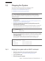
Stopping the System
6.1
Stopping the system with an XSCF command
37
5.2.2
Stopping the system from the operation panel
38
Accessing Components
38
5.3.1
Removing the power cords
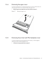
5.3.2
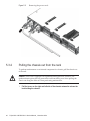
Pulling the chassis out from the rack
5.3.3
Opening the fan cover
5.3.4
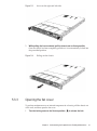
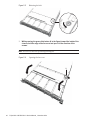
Removing the upper cover
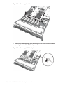
5.3.5
Removing the air duct and PSU backplane cover
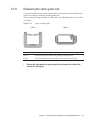
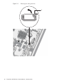
5.3.6
Releasing the cable guide lock
38
40
41
43
43
45
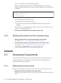
Understanding the Preparations for Restoring the System
47
Incorporating an FRU into the System with the replacefru Command
47
6.2
35
37
5.2.1
Chapter 6
31
32
5.1
5.3
27
28
4.1
4.3
iv
23
Downloading Error Log Information
Chapter 4
23
Starting the System
48
Fujitsu M10-1/SPARC M10-1 Service Manual ・ November 2014
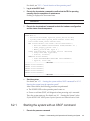
6.3
6.2.1
Starting the system with an XSCF command
49
6.2.2
Starting the system from the operation panel
50
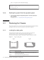
Restoring the Chassis
50
6.3.1
Locking the cable guide
6.3.2
Installing the air duct and PSU backplane cover
6.3.3
Installing the upper cover
6.3.4
Closing the fan cover
6.3.5
Putting the chassis into the rack
6.3.6
Installing the power cords
Chapter 7
50
53
53
55
56
Maintaining the Motherboard Unit
59
7.1
Location of the Motherboard Unit
7.2
Before Maintaining the Motherboard Unit
7.2.1
Types of maintenance
7.2.2
Flow of maintenance
7.2.3
Precautions for replacement
59
60
61
61
61
7.3
Preparing the Motherboard Unit for Removal
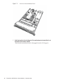
7.4
Removing the Motherboard Unit
Accessing the motherboard unit
63
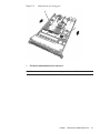
7.4.2
Removing the motherboard unit
64
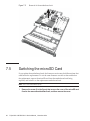
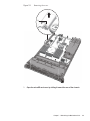
Switching the microSD Card
7.6
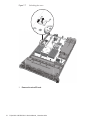
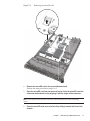
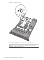
Installing the Motherboard Unit
68
73
7.6.1
Installing the motherboard unit
7.6.2
Restoring the chassis
Restoring the System
Chapter 8
73
80
81
Maintaining Memory
85
8.1
Memory Configuration
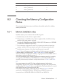
8.2
Checking the Memory Configuration Rules
8.3
62
63
7.4.1
7.5
7.7
51
85
8.2.1
Memory installation rules
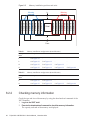
8.2.2
Checking memory information
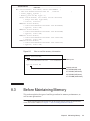
Before Maintaining Memory
89
8.3.1
90
Types of maintenance
87
87
88
Contents
v
8.3.2
Flow of maintenance
90
8.3.3
Precautions for replacement
8.3.4
Precautions for expansion
8.3.5
Precautions for removal
90
91
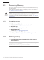
8.4
Enabling the Removal of Memory
8.5
Removing Memory
8.6
8.7
Accessing memory
92
8.5.2
Removing memory
92
93
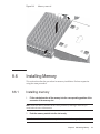
8.6.1
Installing memory
8.6.2
Restoring the chassis
Restoring the System
Chapter 9
91
92
8.5.1
Installing Memory
90
93
94
94
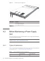
Maintaining the Power Supply Units
95
9.1
Configuration of the Power Supply Units
95
9.2
Before Maintaining a Power Supply Unit
96
9.3
9.2.1
Types of maintenance
96
9.2.2
Flow of maintenance
9.2.3
Precautions for replacement
97
97
Enabling the Removal of a Power Supply Unit
97
9.3.1
Active/hot maintenance
98
9.3.2
Inactive/hot maintenance (system stopped/hot maintenance)
9.3.3
Inactive/cold maintenance (system stopped/cold maintenance)
99
100
9.4
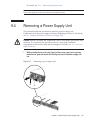
Removing a Power Supply Unit
9.5
Installing a Power Supply Unit
9.6
Restoring the System
101
102
102
9.6.1
Active/hot maintenance
102
9.6.2
Inactive/hot maintenance (system stopped/hot maintenance) 104
9.6.3
Inactive/cold maintenance (system stopped/cold maintenance)
105
Chapter 10
vi
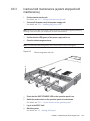
Maintaining the Fan Units
Fujitsu M10-1/SPARC M10-1 Service Manual ・ November 2014
107
10.1
Configuration of the Fan Units
107
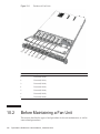
10.2
Before Maintaining a Fan Unit
108
10.3
10.2.1
Types of maintenance
109
10.2.2
Flow of maintenance
10.2.3
Precautions for replacement
109
109
Enabling the Removal of a Fan Unit
110
10.3.1
Active/hot maintenance
110
10.3.2
Inactive/hot maintenance (system stopped/hot maintenance)
110
10.3.3
Inactive/cold maintenance (system stopped/cold maintenance)
111
10.4
10.5
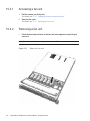
Removing a Fan Unit
10.4.1
Accessing a fan unit
112
10.4.2
Removing a fan unit
112
Installing a Fan Unit
10.5.1
10.6
111
113
Installing a fan unit
Restoring the System
113
113
10.6.1
Active/hot maintenance
113
10.6.2
Inactive/hot maintenance (system stopped/hot maintenance)
114
10.6.3
Inactive/cold maintenance (system stopped/cold maintenance)
114
Chapter 11
11.1
Maintaining the Internal Disks
117
Configuration of the Internal Disks
117
11.1.1
11.2
11.3
Disk slot number
118
Before Maintaining an Internal Disk
11.2.1
Types of maintenance
11.2.2
Flow of maintenance
11.2.3
Precautions for expansion
122
11.2.4
Precautions for reduction
122
121
121
121
Enabling the Removal of an Internal Disk
122
Contents
vii
11.3.1
Active/hot maintenance
122
11.3.2
Inactive/hot maintenance (system stopped/hot maintenance)
124
11.3.3
Inactive/cold maintenance (system stopped/cold maintenance)
124
11.4
Removing an Internal Disk
11.5
Installing an Internal Disk
11.6
Restoring the System
124
126
126
11.6.1
Active/hot maintenance
126
11.6.2
Inactive/hot maintenance (system stopped/hot maintenance)
127
11.6.3
Inactive/cold maintenance (system stopped/cold maintenance)
128
Chapter 12
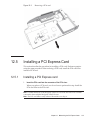
Maintaining the PCI Express Cards
12.1
Configuration of the PCIe Cards
129
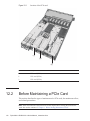
12.2
Before Maintaining a PCIe Card
130
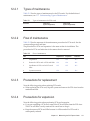
12.2.1
Types of maintenance
12.2.2
Flow of maintenance
12.2.3
Precautions for replacement
12.2.4
Precautions for expansion
131
12.2.5
Precautions for reduction
132
129
131
131
131
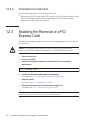
12.3
Enabling the Removal of a PCI Express Card
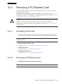
12.4
Removing a PCI Express Card
12.5
12.6
133
12.4.1
Accessing a PCIe card
133
12.4.2
Removing a PCI Express riser
12.4.3
Removing a PCIe card
134
Installing a PCI Express Card
135
12.5.1
Installing a PCI Express card
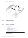
12.5.2
Installing a PCIe riser
12.5.3
Restoring the chassis
Restoring the System
137
viii Fujitsu M10-1/SPARC M10-1 Service Manual ・ November 2014
133
136
136
135
132
Chapter 13
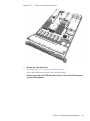
Maintaining the PSU Backplane
139
13.1
Position of the PSU Backplane
139
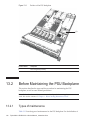
13.2
Before Maintaining the PSU Backplane
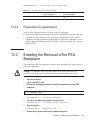
13.2.1
Types of maintenance
13.2.2
Precautions for replacement
140
140
141
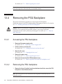
13.3
Enabling the Removal of the PSU Backplane
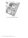
13.4
Removing the PSU Backplane
13.5
13.6
142
13.4.1
Accessing the PSU backplane
142
13.4.2
Removing the PSU backplane
142
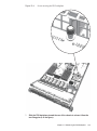
Installing the PSU Backplane
148
13.5.1
Installing the PSU backplane
13.5.2
Restoring the chassis
Restoring the System
Chapter 14
148
151
151
Maintaining the HDD Backplane
153
14.1
Position of the HDD Backplane
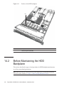
14.2
Before Maintaining the HDD Backplane
153
14.2.1
Types of maintenance
14.2.2
Precautions for replacement
154
155
155
14.3
Enabling the Removal of the HDD Backplane
14.4
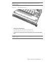
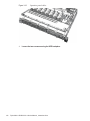
Removing the HDD Backplane
14.5
14.6
Accessing the HDD backplane
156
14.4.2
Removing the HDD backplane
156
Installing the HDD Backplane
160
14.5.1
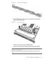
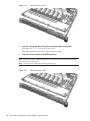
Installing the HDD backplane
14.5.2
Restoring the chassis
Chapter 15
155
156
14.4.1
Restoring the System
141
160
163
163
Maintaining the Operation Panel
165
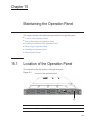
15.1
Location of the Operation Panel
15.2
Before Maintaining the Operation Panel
15.2.1
Types of maintenance
15.2.2
Flow of maintenance
165
166
166
166
Contents
ix
15.2.3
166
15.3
Enabling the Removal of the Operation Panel
15.4
Removing the Operation Panel
15.5
15.6
167
15.4.1
Accessing the operation panel
168
15.4.2
Removing the operation panel
168
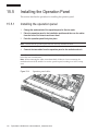
Installing the Operation Panel
170
15.5.1
Installing the operation panel
15.5.2
Restoring the chassis
Restoring the System
Chapter 16
170
171
171
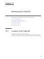
Maintaining the Cable Kit
173
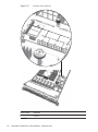
16.1
Location of the Cable Kit
16.2
Before Maintaining the Cable Kit
173
16.2.1
Types of maintenance
16.2.2
Flow of maintenance
175
175
175
16.3
Enabling the Removal of the Cable Kit
16.4
Removing the Cable Kit
16.5
16.6
x
Precautions for replacement
176
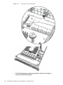
16.4.1
Accessing the cable kit
176
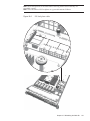
16.4.2
Removing the cable kit
177
Installing the Cable Kit
182
16.5.1
Installing the cable kit
16.5.2
Restoring the chassis
Restoring the System
182
185
185
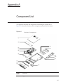
Appendix A
Component List
Appendix B
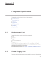
Component Specifications
B.1
Motherboard Unit
B.2
Power Supply Unit
B.3
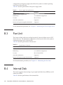
Fan Unit
B.4
Internal Disk
B.5
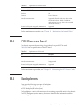
PCI Express Card
B.6
Backplanes
B.7
Operation Panel
187
189
189
190
190
191
191
193
Fujitsu M10-1/SPARC M10-1 Service Manual ・ November 2014
189
175
167
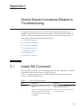
Appendix C
Oracle Solaris Commands Related to Troubleshooting
C.1
iostat(1M) Command
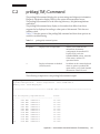
C.2
prtdiag(1M) Command
197
C.3
prtconf(1M) Command
200
C.4
netstat(1M) Command
203
C.5
ping(1M) Command
C.6
ps(1) Command
C.7
prstat(1M) Command
Appendix D
D.1
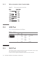
D.1.1
204
206
207
209
209
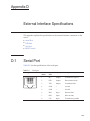
Wire connection chart of serial cable
D.2
USB Port
210
D.3
SAS Port
210
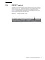
D.4
RESET switch
Index
195
External Interface Specifications
Serial Port
195
210
211
213
Contents
xi
xii
Fujitsu M10-1/SPARC M10-1 Service Manual ・ November 2014
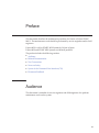
Preface
This document describes the maintenance procedure for Oracle or Fujitsu SPARC
M10-1. The maintenance work should be performed by service engineers and/or field
engineers.
Fujitsu M10 is sold as SPARC M10 Systems by Fujitsu in Japan.
Fujitsu M10 and SPARC M10 Systems are identical products.
The preface includes the following sections:
Audience
■
■
Related Documentation
■
Text Conventions
■
Notes on Safety
■
Syntax of the Command-Line Interface (CLI)
■
Document Feedback
Audience
This document is intended for service engineers and field engineers who perform
maintenance work on the system.
xiii
Related Documentation
All documents for your server are available online at the following sites:
Sun Oracle software-related documents (Oracle Solaris, etc.)
http://www.oracle.com/documentation/
■
■
Fujitsu documents
Japanese site
http://jp.fujitsu.com/platform/server/sparc/manual/
Global site
http://www.fujitsu.com/global/services/computing/server/sparc/downloads/manual/
The following table lists documents related to SPARC M10 Systems.
Documentation Related to SPARC M10 Systems (*1)
Fujitsu M10/SPARC M10 Systems Getting Started Guide (*2)
Fujitsu M10/SPARC M10 Systems Quick Guide
Fujitsu M10/SPARC M10 Systems Important Legal and Safety Information (*2)
Software License Conditions for Fujitsu M10/SPARC M10 Systems
Fujitsu M10/SPARC M10 Systems Safety and Compliance Guide
Fujitsu M10/SPARC M10 Systems Security Guide
Fujitsu M10/SPARC M10 Systems/SPARC Enterprise/PRIMEQUEST Common Installation Planning Manual
Fujitsu M10/SPARC M10 Systems Installation Guide
Fujitsu M10-1/SPARC M10-1 Service Manual
Fujitsu M10-4/Fujitsu M10-4S/SPARC M10-4/SPARC M10-4S Service Manual
Crossbar Box for Fujitsu M10/SPARC M10 Systems Service Manual
PCI Expansion Unit for Fujitsu M10/SPARC M10 Systems Service Manual
Fujitsu M10/SPARC M10 Systems PCI Card Installation Guide
Fujitsu M10/SPARC M10 Systems System Operation and Administration Guide
Fujitsu M10/SPARC M10 Systems Domain Configuration Guide
Fujitsu M10/SPARC M10 Systems XSCF Reference Manual
Fujitsu M10/SPARC M10 Systems RCIL User Guide (*3)
Fujitsu M10/SPARC M10 Systems XSCF MIB and Trap Lists
Fujitsu M10/SPARC M10 Systems Product Notes
Fujitsu M10/SPARC M10 Systems Glossary
*1 The listed manuals are subject to change without notice.
*2 Printed manuals are provided with the product.
*3 This document applies specifically to the FUJITSU M10 and FUJITSU ETERNUS storage system.
xiv Fujitsu M10-1/SPARC M10-1 Service Manual ・ November 2014
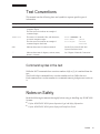
Text Conventions
This manual uses the following fonts and symbols to express specific types of
information.
Font/Symbol
Meaning
Example
AaBbCc123
What you type, when contrasted with on-screen
computer output.
This font is used to indicate an example of
command input.
XSCF> adduser jsmith
AaBbCc123
The names of commands, files, and directories;
on-screen computer output.
This font is used to indicate an example of
command input in the frame.
XSCF> showuser -P
jsmith
User Name:
Privileges:
useradm
auditadm
Italic
Indicates the name of a reference manual.
See the Fujitsu M10/SPARC M10
Systems Installation Guide.
""
Indicates the names of chapters, sections, items,
buttons, or menus.
See "Chapter 2 Network Connection."
Command syntax in the text
While the XSCF commands have a section number of (8) or (1), it is omitted from the
text.
The Oracle Solaris commands have a section number such as (1M) in the text.
Each command has a section number in a command name to prompt users to refer to
it.
Notes on Safety
Read the following documents thoroughly before using or handling any SPARC M10
Systems.
■
Fujitsu M10/SPARC M10 Systems Important Legal and Safety Information
■
Fujitsu M10/SPARC M10 Systems Safety and Compliance Guide
Preface
xv
Syntax of the Command-Line Interface
(CLI)
The command syntax is as follows:
A variable that requires the input of a value must be put in Italics.
■
■
■
An optional element must be enclosed in [].
A group of options for an optional keyword must be enclosed in [] and delimited
by |.
Document Feedback
If you have any comments or requests regarding this document, please take a
moment to share it with us by indicating the manual code, manual title, and page,
and stating your points specifically through the following websites:
■
Japanese site
http://jp.fujitsu.com/platform/server/sparc/manual/
■
Global site
http://www.fujitsu.com/global/services/computing/server/sparc/downloads/manual/
xvi Fujitsu M10-1/SPARC M10-1 Service Manual ・ November 2014
Chapter 1
Before Starting Maintenance Work
This chapter describes the safety precautions that must be observed before starting
any maintenance work.
Note the meanings of each of the following symbols and labels to ensure that the
work is done correctly.
■
Warning/Caution Indications
1.1
■
Labels/Tags
■
Notes on Safety
■
Notes on Static Electricity
■
Other Precautions
■
Emergency Power Off
Warning/Caution Indications
This manual uses the following conventions to indicate warning and alert messages,
which are intended to prevent injury to the user and others as well as damage to
property.
Warning - "WARNING" indicates a potential hazard that could result in death or
serious personal injury if the user does not perform the procedure correctly.
Caution - "CAUTION" indicates a potential hazard that could result in minor or
moderate personal injury if the user does not perform the procedure correctly. This
also indicates that damage to the unit itself or other property may occur if the user
does not perform the procedure correctly.
1
1.2
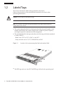
Labels/Tags
This section describes the labels and tags attached to the chassis.
Observe the precautions of the standard labels attached to the chassis when
performing maintenance.
Caution - Do not remove the labels or tags.
Note - The contents of the labels and tags described here may differ from those that are
actually affixed to the chassis.
■
■
The system name plate label (A in the figure) describes the model number, serial
number, manufacture date, rated voltage/current, number of phases, frequency,
and weight required for maintenance and management.
The standard label (B in the figure) describes the following certification standards.
Safety: NRTL/C
■
- Radio wave: VCCI-A, FCC-A, DOC-A, and KCC
- Safety and radio wave: CE, CCC, BSMI, RCM, and EAC
Figure 1-1
Location of the system name plate label and standard label
B
A
■
2
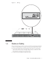
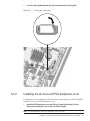
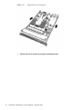
The RFID tag carries an Asset ID. The RFID tag is affixed to the operation panel.
Fujitsu M10-1/SPARC M10-1 Service Manual ・ November 2014
Figure 1-2
1.3
RFID tag
Notes on Safety
Observe the following precautions to protect yourself when performing maintenance.
■
Observe all the precautions, warnings, and instructions described on the chassis.
■
■
Do not insert foreign objects into the openings in the chassis. Any such foreign
object could come into contact with high-voltage circuitry or could short circuit
the components, causing a fire or an electric shock.
Contact your service engineer to inspect the chassis.
Chapter 1
Before Starting Maintenance Work
3
Electrical safety
■
■
■
■
Confirm that the voltage and frequency of your input power supply match the
electric rating described on the system name plate label affixed on the chassis.
Wear a wrist strap when handling an internal disk, a mother board unit, or other
printed boards.
Use grounded power outlets.
Do not attempt to make any mechanical or electrical modifications. Fujitsu shall
not be responsible for the regulatory compliance of a chassis that has been modified.
Rack-related safety precautions
■
■
■
Racks should be fixed to the floor, ceiling, or an adjacent frame.
The racks may be supplied with a quakeresistant options kit. The use of the
quakeresistant options kit prevents the racks from falling over when sliding a
chassis out on a slide rail, either for installation or maintenance.
Prior to installation or maintenance, a safety assessment should be conducted by a
service engineer in the following cases:
■
When the quakeresistant options kit is not supplied and the rack is not fixed to
the floor with bolts: Confirm safety by checking whether the rack could fall
over, etc. when a chassis is pulled out on the slide rail.
■
■
■
When the rack is to be installed on a raised floor: Check that the raised floor can
bear the load when a chassis is pulled out on the slide rail.
If the chassis is mounted at the 20U level or higher, use a step ladder.
If multiple chassis are mounted in a rack, perform maintenance for each of the
chassis.
For details of the racks, see "Chapter 2 Planning and Preparing for System
Installation" in the SPARC M10 Systems Installation Guide.
1.4
Notes on Static Electricity
Observe the precautions related to electrostatic discharge (ESD) as described in Table
1-1 to ensure the safety of personnel and the system.
Table 1-1
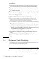
4
ESD precautions
Item
Precautions
Wrist strap
Wear an antistatic wrist strap when handling printed boards.
ESD mat
An approved ESD mat provides protection from static damage
when used with a wrist strap. The mat also acts as a cushion to
protect the small parts that are attached to printed boards.
Fujitsu M10-1/SPARC M10-1 Service Manual ・ November 2014
Table 1-1
ESD precautions (continued)
Item
Precautions
Antistatic bag/
ESD safe packaging box
After removing a printed board or component, place it in the
antistatic bag or ESD safe packaging box.
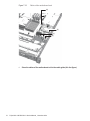
How to use a wrist strap
Wear a wrist strap in such a way that the inner metal surface (A in the figure) of the
wrist strap band is in contact with your skin. Connect the clip (B in the figure)
directly to the chassis.
Caution - Do not connect the wrist strap clip to the ESD mat. By connecting the wrist
strap clip to the chassis, the operator and components have the same electrical
potential, thus eliminating the danger of static damage.
Figure 1-3
Wrist strap connection destination
A
B
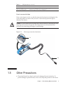
1.5
Other Precautions
■
The printed boards in a chassis can be easily damaged by static electricity. To
prevent damage to printed boards, wear a wrist strap and ground it to the chassis
Chapter 1
Before Starting Maintenance Work
5
prior to starting maintenance.
■
If excessive force is applied to the motherboard unit, the components mounted on
the printed boards could be damaged. When handling the motherboard unit,
observe the following precautions:
■
Handle the motherboard unit by holding it by the handle.
■
■
■
■
■
■
1.6
When removing the motherboard unit from its packaging, keep the motherboard
unit horizontal until you lay it on the cushioned ESD mat.
Connectors and components on the motherboard unit have thin pins that bend
easily. Therefore, do not place the motherboard unit on a hard surface.
Be careful not to damage the small parts mounted on both sides of the
motherboard unit.
The heat sinks can be damaged by incorrect handling. Do not touch the heat sinks
with your hands or other objects while replacing or removing motherboard units.
If a heat sink becomes disconnected or is broken, obtain a replacement motherboard
unit. When storing or carrying a motherboard unit, ensure that the heat sinks are
sufficiently protected.
When removing a cable such as the LAN cable, if you cannot reach the latch lock
of the connector, use a flat headed screwdriver to push the latch and release the
cable. If you use force to remove the cable, the LAN port of the motherboard unit
or a PCI Express (PCIe) card may be damaged.
Do not use any power cords other than those specified.
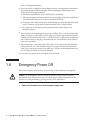
Emergency Power Off
This section explains the procedure for powering off the system in an emergency.
Caution - In an emergency (such as smoke or flames coming from the chassis),
immediately stop using the unit and turn off the power supply. Regardless of the
operation you are performing, give top priority to fire prevention.
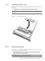
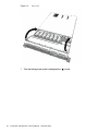
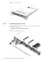
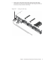
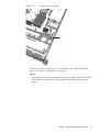
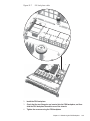
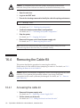
1.
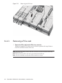
6
Remove all the power cords from the power supply units.
Fujitsu M10-1/SPARC M10-1 Service Manual ・ November 2014
Figure 1-4
Removing the power cords
Chapter 1
Before Starting Maintenance Work
7
8
Fujitsu M10-1/SPARC M10-1 Service Manual ・ November 2014
Chapter 2
Understanding the System
Components
This section describes the components mounted on the SPARC M10-1.
It is necessary to confirm and fully understand the configurations of the components
mounted in the chassis as well as the LED indications before starting any maintenance
work.
■
Identifying the Names and Locations of Components
■
Confirming the Functions of the Operation Panel
■
Checking the LED Indications
For the specifications of each component, see "Appendix B Component Specifications."
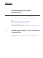
2.1
Identifying the Names and Locations of
Components
This section describes the names and locations of the components mounted on the
SPARC M10-1.
9
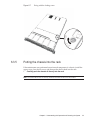
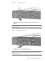
Components that can be accessed from the front
Figure 2-1
Location of components that can be accessed from the front
(1)
Location
number
Component
1
Internal disk
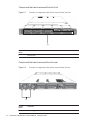
Components that can be accessed from the rear
Figure 2-2
Location of components that can be accessed from the rear
(1)
10
Location
number
Component
1
Power supply unit
Fujitsu M10-1/SPARC M10-1 Service Manual ・ November 2014
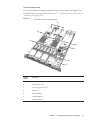
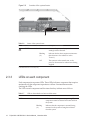
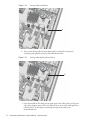
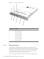
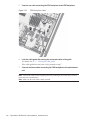
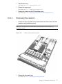
Internal components
To access the internal components, open the fan cover and remove the upper cover.
For details on how to remove the covers, see "5.3.3 Opening the fan cover" or "5.3.4
Removing the upper cover."
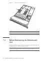
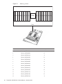
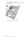
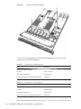
Figure 2-3
Locations of internal components
(3)
(2)
(1)
(4)
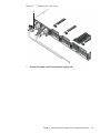
(5)
(6)
(7)
Location
number
Component
1
Fan unit
2
Motherboard unit
3
PCI Express (PCIe) card
4
Memory
5
PSU backplane
6
HDD backplane
7
Operation panel
Chapter 2
Understanding the System Components
11
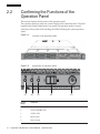
2.2
Confirming the Functions of the
Operation Panel
This section explains the functions of the operation panel.
The operation panel provides the system's display and control functions. The field
engineer and system administrator can specify the operation mode or control
start/stop of the system while checking the LEDs indicating the system operation
status.
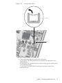
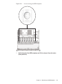
Figure 2-4
Location of the operation panel
Figure 2-5
Appearance of operation panel
(1)
12
(2)
(3)
Location
number
Component
1
POWER LED
2
XSCF STANDBY LED
3
CHECK LED
4
Mode switch
5
Power switch
(4)
Fujitsu M10-1/SPARC M10-1 Service Manual ・ November 2014
(5)
2.2.1
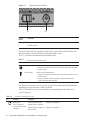
Display function of the operation panel
The operation panel has three LED indicators as a display function. The LED
indicators represent the following items. For details, see "2.3.1 Operation panel
LEDs."
■
General system status
■
System error warning
■
System error location
Figure 2-6
(1)
2.2.2
Operation panel LEDs
(2)
(3)
Location
number
Component
1
POWER LED
2
XSCF STANDBY LED
3
CHECK LED
Control function of the operation panel
The operation panel has the following switches as a control function:
■
Mode switch (slide switch)
Specifies the operation or maintenance mode.
■
POWER switch
Controls start/stop of the system.
Chapter 2
Understanding the System Components
13
Figure 2-7
Operation panel switches
(1)
(2)
Location
number
Component
1
Mode switch
2
POWER switch
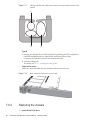
The mode switch sets the operation mode for the system. The Locked and Service
operation modes can be switched by sliding the mode switch.
Table 2-1 describes the difference between the modes.
Table 2-1
Icon
Functions of the mode switch
Name
Description
Locked mode
Mode used for normal operation
- The power switch can be used to start the system but cannot be
used to stop it.
Service mode
Mode used for maintenance
- The power switch cannot be used to start the system but can be
used to stop it.
- Place the system in Service mode to perform maintenance
work with the system stopped.
Use the power switch to start or stop the system. The system starts/stops differently
depending on how the power switch is pressed.
Table 2-2 describes how system starts/stops vary depending on how the power
switch is pressed.
Table 2-2
Icon
14
Functions of the power switch
Operation
Description
Brief press
(For 1 second or
more and less than 4
seconds)
If the system has been
started in Service mode:
Operation is ignored.
If the system is stopped in
Service mode:
Operation is ignored.
Fujitsu M10-1/SPARC M10-1 Service Manual ・ November 2014
Table 2-2
Icon
Functions of the power switch (continued)
Operation
Description
Long press
(For 4 seconds or
more)
If the system has been
started in Locked mode:
Operation is ignored.
If the system is stopped in
Locked mode:
Starts the system.
At this time, if a wait time for the air conditioning
facilities or a warm-up time is set on the XSCF,
the processing for waiting for the power-on of the
air conditioning facilities and the completion of
warm-up is omitted.
If the system has been
started in Service mode:
Perform the system shutdown process to stop the
system.
If the system startup
process is in progress in
Service mode:
Cancels the system startup process and stops the
system.
If the system stop process
is in progress in Service
mode:
Continues the system stop process.
If the system is stopped in
Service mode:
Operation is ignored.
The system does not start even after holding
down the power switch.
If the system is stopped in
Locked mode:
Starts the system.
If a wait time for the air conditioning facilities or
a warm-up time is set on the XSCF, the
processing for waiting for the power-on of the air
conditioning facilities and the completion of
warm-up is omitted.
If the system is not
stopped in Locked mode:
Operation is ignored.
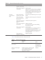
Table 2-3 describes the functions of the mode switch.
Table 2-3
Functions of the mode switch
Function
Mode switch
Locked
Service
Start/stop of the system by the
power switch
Only system startup is enabled.
The system can
be powered off
by holding down
the power switch.
Inhibition of break signal
reception
Enabled. Reception of the break signal
can be enabled/disabled for each
physical partition by using the
setpparmode command.
Disabled
Chapter 2
Understanding the System Components
15
2.3
Checking the LED Indications
This section describes the indications given by the system LEDs.
LEDs are mounted on the operation panel on the front of the chassis, on the rear
panel of the chassis, and on those components that can be maintained. If an error
occurs, the LED indication enables you to determine the system that requires
maintenance.
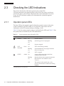
2.3.1
Operation panel LEDs
The three LEDs on the operation panel indicate the operation status of the entire
system. In addition, the LEDs enable you to check the system status with the
combination of the LED statuses (being on, blinking, or off).
Table 2-4 lists the system operation status as indicated by the LEDs and Table 2-5 lists
the system status as indicated by the LED combinations.
Table 2-4
Icon
System operation status indicated by LEDs
Name
Color
Status
Description
POWER
Green
On
System is started.
Blinking
(*1)
System stop process is in progress.
Off
System is stopped.
On
XSCF is functioning normally.
Blinking
(*1)
System initialization is in progress after the
turn-on of the power.
Off
XSCF is stopped.
On
An error that prevents the system from
starting has been detected.
Blinking
(*1)
Indicates that the chassis requires maintenance
(this function is also referred to as the
"locator").
Off
The system is in the normal state, or the
power is disconnected or otherwise not being
supplied.
XSCF
STANDBY
CHECK
Green
Amber
*1 The blink interval is 1 second (1 Hz).
16
Fujitsu M10-1/SPARC M10-1 Service Manual ・ November 2014
Table 2-5
System status indicated by combination of LEDs
LED state
Description
POWER
XSCF
STANDBY
CHECK
Off
Off
Off
Power is disconnected.
Off
Off
On
Power has just been turned on.
The XSCF has detected an error.
Off
Blinking
(*1)
Off
The XSCF is being initialized.
Off
On
Off
The XSCF is in the standby state.
The system is waiting for power-on of the air
conditioning facilities (in the data center).
On
On
Off
Warm-up standby processing is in progress. Once
processing is complete, the system starts up.
System startup processing is in progress.
The system is operating.
On
On
On
Although the system is operating normally, an
error has been detected.
Blinking
(*1)
On
Off
System stop processing is in progress. Once
processing is complete, the fan unit stops.
*1 The blink interval is 1 second (1 Hz).
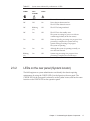
2.3.2
LEDs on the rear panel (System locator)
The field engineer or system administrator can identify the chassis requiring
maintenance by using the CHECK LED (A in the figure) on the rear panel. The
CHECK LED on the rear panel is referred to as the system locator, and has the same
function as the CHECK LED on the operation panel.
Chapter 2
Understanding the System Components
17
Figure 2-8
Location of the system locator
A
Table 2-6
Icon
Status of the system locator
Name
Color
Status
Description
CHECK
Amber
On
An error that prevents the system from
starting has been detected.
Blinking
(*1)
Indicates that the chassis requires maintenance
(this function is also referred to as the
"locator").
Off
The system is in the normal state, or the
power is disconnected or otherwise not being
supplied.
*1 The blink interval is 1 second (1 Hz).
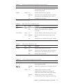
2.3.3
LEDs on each component
Each component incorporates LEDs. These LEDs indicate a component that requires
maintenance if that component experiences a failure. Start maintenance after
checking the LEDs.
The LEDs on each component and the states that they indicate are as follows:
Table 2-7
18
LEDs on the motherboard unit and their states
Name
Color
Status
Description
READY
Green
On
Indicates that the component is operating. The
component cannot be released and removed from
the system.
Blinking
(*1)
Indicates that the component is currently being
mounted on the system or being disconnected
from the system.
Fujitsu M10-1/SPARC M10-1 Service Manual ・ November 2014
Table 2-7
Name
CHECK
LEDs on the motherboard unit and their states (continue d)
Color
Amber
Status
Description
Off
Indicates that the component is disconnected from
the system. Indicates that the component can be
removed and replaced.
On
Indicates that an error has occurred.
Blinking
(*1)
Indicates that the component requires maintenance
(this function is also referred to as the "locator").
Off
Indicates the normal state.
*1 The blink interval is 1 second (1 Hz).
Table 2-8
LEDs on the LAN port and their states
Name
Color
Status
Description
ACT
Green
On
Indicates that communication is being performed.
Off
Indicates that communication is not being
performed.
Amber
On
Indicates that the communication speed is 1 Gbps.
Green
Blinking
(*1)
Indicates that the communication speed is 100
Mbps.
Off
Indicates that the communication speed is 10 Mbps.
LINK SPEED
*1 The blink interval is 1 second (1 Hz).
Table 2-9
LED on the fan unit and its states
Name
Color
Status
Description
CHECK
Amber
On
Indicates that an error has occurred.
Blinking
(*1)
Indicates that the component requires maintenance
(this function is also referred to as the "locator").
Off
Indicates the normal state.
*1 The blink interval is 1 second (1 Hz).
Table 2-10
Name
CHECK
LED on the power supply unit and its states
Color
Status
Description
Green
On
Indicates that the input power is turned on and
being supplied normally.
Blinking
(*1)
Indicates that the input power is being disconnected.
On
Indicates that an error has occurred.
Indicates that the input power to this power
supply unit is turned off in redundant operation.
Blinking
(*1)
Indicates the warning status (an error has
occurred but the power supply unit is operating).
Amber
Chapter 2
Understanding the System Components
19
Table 2-10
Name
LED on the power supply unit and its states (continued)
Color
Status
Description
Off
Indicates that power is not being supplied.
*1 The blink interval is 1 second (1 Hz).
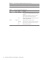
Table 2-11
LEDs on the internal disk and their states
Name
Color
Status
Description
READY
Green
Blinking
Indicates that the disk is being accessed. This LED
is normally on, but it blinks while the disk is being
accessed.
While the LED is blinking, maintenance such as
removal of the disk cannot be performed.
Off
Indicates that maintenance such as the removal of
the disk can be performed.
On
Indicates that an error has occurred.
Blinking
(*1)
Indicates that the component requires maintenance
(this function is also referred to as the "locator").
Off
Indicates the normal state.
CHECK
Amber
*1 The blink interval is 1 second (1 Hz).
20
Fujitsu M10-1/SPARC M10-1 Service Manual ・ November 2014
Chapter 3
Troubleshooting
This chapter describes how to determine and confirm the cause if an error occurs.
■
Suspected Failure Conditions
3.1
■
Determining the Causes of Failures
■
Identifying a Failure
■
Downloading Error Log Information
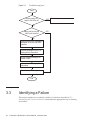
Suspected Failure Conditions
This section explains suspected failure conditions. Use the flow to determine the
cause of a failure and identify the failure location in the following cases. For details
on the flow for determining the cause of a failure, see "3.2 Determining the Causes
of Failures."
■
When the CHECK LED is on
■
■
■
3.2
When an error message is displayed on the console
When an error is displayed as a result of executing a command for checking the
status
When an error is displayed in the error log
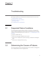
Determining the Causes of Failures
This section explains the flow for determining the causes of failures. Also apply this
flow to identify failures in the PCI expansion unit.
21
Figure 3-1
Troubleshooting flow
Start
Are the power OK
and AC OK LEDs off?
YES
Check the power and connection.
NO
Was e-mail sent by the
XSCF mail function?
YES
NO
Confirm that an error message is
displayed on the OS and XSCF
consoles.
Execute showlogs on XSCF to
display failure information.
Check /var/adm/messages on
Oracle Solaris.
Write down the displayed failure
information.
Contact our service engineer.
End
3.3
Identifying a Failure
This section explains how to identify a failure. Use the flow described in "3.2
Determining the Causes of Failures" to determine the appropriate way of checking
for a failure.
22
Fujitsu M10-1/SPARC M10-1 Service Manual ・ November 2014
3.3.1
Checking the LED indications
Check the LEDs on the operation panel, rear panel, and on each component to
identify a component requiring maintenance. Check the status of a component from
its LED before starting any maintenance work on that component.
■
Operation panel LEDs
You can determine the status of the system by checking the LEDs on the operation
panel. For details, see "2.3.1 Operation panel LEDs."
■
■
Rear panel LED
You can determine the status of the system by checking the CHECK LED on the
rear panel of the chassis, which duplicates the CHECK LED on the operation
panel. For details, see "2.3.2 LEDs on the rear panel (System locator)."
LED on each component
You can determine the location of an error by checking the LED on the component
that incorporates the failed hardware if an error occurs with the hardware in the
chassis. For details, see "2.3.3 LEDs on each component."
Note that some components, such as memory, are not provided with LEDs. To
check the status of a component that does not have an LED, execute XSCF shell
commands such as the showhardconf command from the maintenance terminal.
For details, see "3.3.3 Checking the status of a component."
3.3.2
Checking error messages
Display error messages to check the log information and an error overview.
You can use either of the following two methods to check the error messages:
■
Checking error log information using the XSCF shell
For details, see "12.1 Checking Log Saved with XSCF" in the SPARC M10 Systems
System Operation and Administration Guide.
■
3.3.3
Checking messages on Oracle Solaris
For details, see "12.2 Checking Warning and Notification Messages" in the SPARC
M10 Systems System Operation and Administration Guide.
Checking the status of a component
Execute XSCF firmware commands to determine the system hardware configuration
and the status of each component.
showhardconf command
Execute the showhardconf command to determine the information on the component.
1. Log in to the XSCF shell.
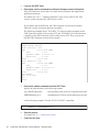
2.
Execute the showhardconf command to acquire a list of components.
A failed component is indicated by an asterisk (*) at the beginning of the line.
Chapter 3
Troubleshooting
23
XSCF> showhardconf
SPARC M10-1;
+ Serial:2101151008A; Operator_Panel_Switch:Locked;
+ System_Power:Off; System_Phase:Cabinet Power Off;
------------------------Omitted-----------------------PCI#1 Status:Normal; Name_Property:;
+ Vendor-ID:14e4; Device-ID:1648;
+ Subsystem_Vendor-ID:10cf; Subsystem-ID:13a0;
+ Model: LPe1250-F8-FJ;
+ Connection:PCIBOX#X07P;
*
PCIBOX#X0DF Status:Faulted; Ver:0512 Serial:XCX0DF;
+ FRU-Part-Number:CF00541-0314 05
/501-6937-05;
IOB Status:Normal; Serial:XX00KA; Type:PCI-X;
+ FRU-Part-Number:CF00541-0316 03
/501-6938-05;
LINKBORAD Status:Faulted; Ver:0512 Serial:XCX0DF;
/501-6937-05;
+ FRU-Part-Number:CF00541-0314 05
PCI#0 Name_Property:fibre-channel;
+ Vendor-ID:14e4; Device-ID:1648;
+ Subsystem_Vendor-ID:10cf; Subsystem-ID:13a0;
+ Model: LPe1250-F8-FJ;
showstatus command
Execute the showstatus command to determine the status of the component.
1. Log in to the XSCF shell.
2.
Execute the showstatus command to determine the status.
A failed component is indicated by an asterisk (*) at the beginning of the line.
XSCF> showstatus
MBU Status:Normal;
*
MEM#0A Status:Faulted;
The status of a component is displayed after the "Status:" string.
Table 3-1 shows the states of components.
Table 3-1
24
States of components
Display
Description
Normal
The unit is in the normal state.
Faulted
The unit is faulty and is not operating.
Degraded
A part of the unit has failed or degraded, but the unit is running.
Deconfigured
Due to the failure or degradation of another unit, the target unit and
components of its underlying layer has been degraded, though there
is no problem in them.
Maintenance
Maintenance is being performed. The replacefru or addfru command
is being executed.
Fujitsu M10-1/SPARC M10-1 Service Manual ・ November 2014
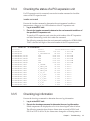
3.3.4
Checking the status of a PCI expansion unit
If a PCI expansion unit is connected, execute the ioxadm command to check the
status of the PCI expansion unit.
ioxadm command
Execute the ioxadm command to determine the environmental conditions
(temperature, voltage, etc.) or LED indications of the PCI expansion unit.
1. Log in to the XSCF shell.
2.
Execute the ioxadm command to determine the environmental conditions of
the specified PCI expansion unit.
To specify a PCI expansion unit, enter the serial number of the PCI expansion
unit after determining it with the ioxadm list command.
The following example shows the environmental conditions for PCIBOX#2008.
"2008" is the last four digits of the serial number of the PCI expansion unit.
XSCF> ioxadm env -te PCIBOX#2008
Location
Sensor
PCIBOX#2008
AIRFLOW
PCIBOX#2008
P_CONSUMPTION
PCIBOX#2008/PSU#0
FAN
PCIBOX#2008/PSU#1
FAN
PCIBOX#2008/FAN#0
FAN
PCIBOX#2008/FAN#1
FAN
PCIBOX#2008/FAN#2
FAN
PCIBOX#2008/IOBT
T_INTAKE
PCIBOX#2008/IOBT
T_PART_NO0
PCIBOX#2008/IOBT
T_PART_NO1
PCIBOX#2008/IOBT
T_PART_NO2
PCIBOX#2008/IOBT
V_12_0V
PCIBOX#2008/IOBT
V_3_3_NO0
PCIBOX#2008/IOBT
V_3_3_NO1
PCIBOX#2008/IOBT
V_3_3_NO2
PCIBOX#2008/IOBT
V_3_3_NO3
PCIBOX#2008/IOBT
V_1_8V
PCIBOX#2008/IOBT
V_0_9V
3.3.5
Value Resolution Units
180.000
0.000 CHM
68.000
0.000 W
3936.000
0.000 RPM
3584.000
0.000 RPM
3374.000
0.000 RPM
3374.000
0.000 RPM
3374.000
0.000 RPM
26.000
0.000 C
31.500
0.000 C
30.750
0.000 C
31.500
0.000 C
12.069
0.000 V
3.293
0.000 V
3.295
0.000 V
3.291
0.000 V
3.300
0.000 V
1.804
0.000 V
0.900
0.000 V
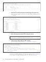
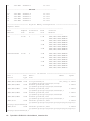
Checking log information
Execute the showlogs command to determine the error log information.
1. Log in to the XSCF shell.
2.
Execute the showlogs command to determine the error log information.
Failed components are displayed as a list in in chronological order of failure.
The following example shows that an Alarm status occurred in PSU#1 and
PSU#2 at 12:45:31 on Oct 20, the Alarm status changed to a Warning status at
Chapter 3
Troubleshooting
25
15:45:31 on the same day, and then the Alarm status further expanded to PSU#1,
PSU#2, and PSU#3 at 17:45:31 on the same day.
XSCF> showlogs error
Date: Oct 20 12:45:31 JST 2012
Code: 00112233-445566778899aabbcc-8899aabbcceeff0011223344
Status: Alarm
Occurred: Oct 20 12:45:31.000 JST 2012
FRU: PSU#1,PSU#2
Msg: ACFAIL occurred (ACS=3)(FEP type = A1)
Date: Oct 20 15:45:31 JST 2012
Code: 00112233-445566778899aabbcc-8899aabbcceeff0011223344
Status: Warning
Occurred: Oct 20 15:45:31.000 JST 2012
FRU: PSU#1,PSU#2
Msg: ACFAIL occurred (ACS=3)(FEP type = A1)
Date: Oct 20 17:45:31 JST 2012
Code: 00112233-445566778899aabbcc-8899aabbcceeff0011223344
Status: Alarm
Occurred: Oct 20 17:45:31.000 JST 2012
FRU: PSU#1,PSU#2, PSU#3,*
Msg: ACFAIL occurred (ACS=3)(FEP type = A1)
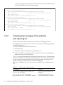
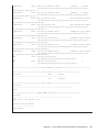
3.3.6
Checking the messages of the predictive
self-repairing tool
Check the messages output from the Oracle Solaris Fault Manager predictive
self-repairing tool, running on Oracle Solaris. Oracle Solaris Fault Manager supports
the following functions:
■
Receives telemetry information about errors.
■
Troubleshooting
■
Disables the components that have experienced errors.
■
Turns on the LED of a component that has experienced an error and displays the
details in the system console message.
Table 3-2 lists typical messages that are generated if an error occurs. These messages
indicate that the fault has already been diagnosed. If corrective actions can be taken
by the system, this indicates that they have already been taken. In addition, if the
system is running, corrective actions continue to be applied.
Messages are displayed on the console and are recorded in the /var/adm/messages
file.
Table 3-2
26
Predictive self-repairing messages
Output Displayed
Description
Nov 1 16:30:20 dt88-292 EVENT-TIME:Tue
Nov 1 16:30:20 PST 2005
EVENT-TIME: Time stamp of the
diagnosis
Nov 1 16:30:20 dt88-292 PLATFORM:
ORCL,SPARC64-X, CSN:-,HOSTNAME:dt88-292
PLATFORM: Description of the
chassis in which the error occurred
Fujitsu M10-1/SPARC M10-1 Service Manual ・ November 2014
Table 3-2
3.3.7
Predictive self-repairing messages (continued)
Output Displayed
Description
Nov 1 16:30:20 dt88-292 SOURCE:eft, REV:1.13
SOURCE: Information on the
diagnosis engine used to identify
the error
Nov 1 16:30:20 dt88-292 EVENT-ID:
afc7e660-d609-4b2f-86b8-ae7c6b8d50c4
EVENT-ID: Universally unique
event ID for this error
Nov 1 16:30:20 dt88-292 DESC:
Nov 1 16:30:20 dt88-292 A problem was detected in
the PCI Express subsystem
DESC: Basic description of the error
Nov 1 16:30:20 dt88-292 Refer to http://support.
oracle.com/msg/SUN4-8000-0Y for more information.
Website: Where to find specific
information and actions to apply in
the event of this error
Nov 1 16:30:20 dt88-292 AUTO-RESPONSE:
One or more device instances may be disabled.
AUTO-RESPONSE: What the
system has done (if anything) to
alleviate any subsequent problems
Nov 1 16:30:20 dt88-292 IMPACT:Loss of services
provided by the device instances associated with this
fault.
IMPACT: Description of the
assumed impact of the failure
Nov 1 16:30:20 dt88-292 REC-ACTION:
Schedule a repair procedure to replace the affected
device.Use Nov 1 16:30:20 dt88-292 fmdump -v –u
EVENT_ID to identify the device or contact Sun for
support.
REC-ACTION: Brief description of
the corrective action the system
administrator should apply
Identifying the location of the chassis requiring
maintenance
Execute the setlocator command to identify the location of the chassis requiring
maintenance by causing the CHECK LED on the operation panel and the CHECK
LED (locator) on the rear panel to blink.
1. Log in to the XSCF shell.
2.
Execute the setlocator command to identify the location of the chassis
requiring maintenance by causing the CHECK LED of the chassis to blink.
The CHECK LEDs on the operation and rear panels blink.
XSCF> setlocator blink
For details on the location of the CHECK LED and the procedure for checking it,
see "2.3 Checking the LED Indications."
Chapter 3
Troubleshooting
27
3.4
Downloading Error Log Information
This section describes the procedure for downloading error log information.
To download error log information, use the XSCF log fetch function. The XSCF has a
USB port that is specifically for maintenance, allowing maintenance information such
as error logs to be easily obtained.
For details, see "12.1.15 Saving a log to a file with snapshot" and "12.1.16 Saving a
log to a local USB device" in Fujitsu M10/SPARC M10 Systems System Operation and
Administration Guide.
28
Fujitsu M10-1/SPARC M10-1 Service Manual ・ November 2014
Chapter 4
Preparing for Maintenance
This chapter describes the preparations that must be completed prior to performing
any maintenance as well as the types of maintenance.
■
Preparing Tools Required for Maintenance
4.1
■
Confirming the System Configuration
■
Understanding Types of Maintenance
Preparing Tools Required for
Maintenance
This section explains the tools required for performing maintenance. Table 4-1 lists
the tools required for maintenance.
Table 4-1
4.2
Maintenance tools
Item
Use
Phillips screwdriver (No.2)
For removing or installing screws
Torx screwdriver (T10)
For removing or installing screws
Wrist strap
For static grounding
ESD mat
For static grounding
Confirming the System Configuration
This section explains how to check the hardware and software configurations.
The system configuration must be the same before and after maintenance work. If an
error occurs in the system, record the system configuration and the states of the
29
components before starting maintenance. Then, after completing maintenance,
confirm that the system configuration is the same as that before maintenance.
4.2.1
Confirming the hardware configuration
Execute the showhardconf command to confirm the configuration and status of the
components mounted on the chassis. Before performing any maintenance work,
check and record the hardware configuration of the chassis.
1. Log in to the XSCF shell.
2.
Execute the showhardconf command to confirm the hardware configuration
information.
XSCF> showhardconf
The following information appears:
Current configuration and status
■
4.2.2
■
Number of mounted Field Replaceable Units (FRU)
■
Status of the unit in which a physical partition error or degradation occurred
■
Information on the PCI expansion unit
■
Name properties of the PCI Express (PCIe) card
Confirming the software and firmware
configurations
The software and firmware configurations and versions affect system operation. To
change the configuration or investigate a problem, check the latest state and check for
any problems in the software.
Confirming the software configuration
Use Oracle Solaris commands to check the software configuration.
If you are logged in to the XSCF console, switch to the control domain console by
executing the console command beforehand.
Table 4-2 lists the commands used for checking the software configuration.
Table 4-2
Command
Description
pkg(1) (Oracle Solaris 11)
showrev(1M) (Oracle Solaris 10)
Displays Oracle Solaris correction information
and the version.
ldm(1M)
Displays logical domain configuration information.
1.
30
Commands for checking the software configuration
Log in to the control domain console of the physical partition where the
Fujitsu M10-1/SPARC M10-1 Service Manual ・ November 2014
component to be maintained is mounted.
For information on how to log in to the control domain console, see "8.3
Switching to the Control Domain Console from the XSCF Shell" in Fujitsu
M10/SPARC M10 Systems System Operation and Administration Guide.
2.
Execute the pkg(1) command to display Oracle Solaris correction information
and the version.
For Oracle Solaris 11, execute the pkg(1) command.
# pkg info entire
Name: entire
Summary: entire incorporation including Support Repository Update
(Oracle Solaris 11.1.12.5.0).
For Oracle Solaris 10, execute the showrev(1M) command.
# showrev -p
To display the version of Oracle VM Server for SPARC, execute the ldm(1M)
command.
# ldm -V
Logical Domains Manager (v 3.1)
Hypervisor control protocol v 1.9
Using Hypervisor MD v 1.3
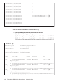
Confirming the firmware configuration
Use XSCF shell commands to confirm the XSCF firmware configuration.
1. Log in to the XSCF shell.
2.
Execute the version command to confirm the firmware version information.
In the following example, "-c xcp" is entered to confirm the overall XCP version.
XSCF> version -c xcp
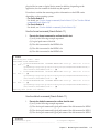
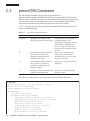
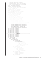
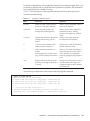
4.2.3
Confirming the FRU information and resource
information
Use XSCF shell commands to check the FRU information and resource information.
Table 4-3 lists the commands used for checking the FRU information and resource
information. For details on each command, see the Fujitsu M10/SPARC M10 Systems
XSCF Reference Manual of the XCP firmware version used.
Chapter 4
Preparing for Maintenance
31
Table 4-3
4.3
Commands for checking FRU information and resource information
Command
Description
showstatus
Displays the FRU status. Out of the FRUs in the system
configuration, this command displays information on a faulty or
degraded unit or FRU.
showboards
Displays information on a physical system board (PSB). Displays
information on a physical system board that belongs to the
specified physical partition and information on all the physical
system boards that are mounted.
showpcl
Displays the configuration information for a physical partition
(hardware resource information).
showfru
Displays the setting information for a device.
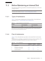
Understanding Types of Maintenance
This section describes the types of maintenance performed on the SPARC M10-1.
The definitions of terms used in this document are as follows.
Table 4-4
Definitions of terms
Term
Definition
Physical partition
requiring maintenance
Physical partition to which SPARC M10-1, in which Field
Replaceable Unit (FRU) requiring maintenance is mounted,
belongs
Chassis requiring
maintenance
Chassis of SPARC M10-1, in which Field Replaceable Unit (FRU)
requiring maintenance is mounted
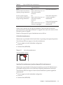
The following three types of maintenance for SPARC M10-1 are available, depending
on the state of the physical partition requiring maintenance in combination with the
state of the input power of the chassis requiring maintenance.
32
Fujitsu M10-1/SPARC M10-1 Service Manual ・ November 2014
Table 4-5
Types of SPARC M10-1 maintenance
State of physical partition requiring
maintenance
State of input power of chassis
requiring maintenance
Type of maintenance
Active
State in which Oracle Solaris is
operating during maintenance
Hot
State in which the power cord
of the chassis remains
connected
Active/hot maintenance
Inactive (system stopped)
State in which Oracle Solaris is
stopped during maintenance
Hot
State in which the power cord
of the chassis remains
connected
Inactive/hot maintenance
(system stopped/hot
maintenance)
Cold
State in which the power cord
of chassis is unplugged
Inactive/cold maintenance
(system stopped/cold
maintenance)
SPARC M10-1 has the only one physical partition. Thus, the state in which the
physical partition requiring maintenance is stopped is the same as the state in which
the entire system is stopped.
Details of the respective types of maintenance are as follows.
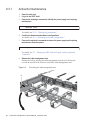
Active/hot maintenance
Maintenance is performed while Oracle Solaris is operating in the physical partition.
The following FRUs are targets of active/hot maintenance.
Power supply unit with redundant configuration
■
■
Fan unit
■
Internal disk (HDD/SSD)
Figure 4-1
Active/hot maintenance
Physical partition (active)
BB#0
Error
Hot
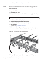
Inactive/hot maintenance (system stopped/hot maintenance)
Maintenance is performed with the physical partition powered off. Maintenance is
performed with the power cord of the chassis requiring maintenance connected.
The following FRUs are targets of inactive/hot maintenance (system stopped/hot
maintenance).
■
Power supply unit with redundant configuration
■
Fan unit
■
Internal disk (HDD/SSD)
Chapter 4
Preparing for Maintenance
33
Figure 4-2
Inactive/hot maintenance (system stopped/hot maintenance)
Physical partition (stopped)
Error
BB#0
Hot
Inactive/cold maintenance (system stopped/cold maintenance)
Maintenance is performed with the physical partition powered off. Maintenance is
performed with the power cord of the chassis requiring maintenance unplugged.
The following FRUs are targets of inactive/cold maintenance (system stopped/cold
maintenance).
■
All FRUs
Figure 4-3
Inactive/cold maintenance (system stopped/cold maintenance)
Physical partition (stopped)
Error
BB#0
Cold
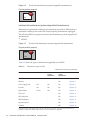
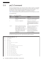
Table 4-6 shows the types of maintenance applicable to each FRU.
Table 4-6
Maintenance types for FRUs
-: Maintenance cannot be performed.
FRU
Active/hot
Inactive/hot
(system
stopped/hot)
Inactive/cold
(system
stopped/cold)
Reference
Motherboard unit
-
-
OK
Chapter 7
Memory
-
-
OK
Chapter 8
Power supply unit
OK
OK
OK
Chapter 9
Fan unit
OK
OK
OK
Chapter 10
Internal disk
OK (*)
OK
OK
Chapter 11
PCIe card
-
-
OK
Chapter 12
PSU backplane
-
-
OK
Chapter 13
HDD backplane
-
-
OK
Chapter 14
Operation panel
-
-
OK
Chapter 15
Cable kit
-
-
OK
Chapter 16
*: Supported only for the internal disk of devices other than a boot device. If, however, the boot device has a
redundant configuration (RAID configuration), active/hot maintenance is supported.
34
Fujitsu M10-1/SPARC M10-1 Service Manual ・ November 2014
Chapter 5
Understanding the Preparations for
Enabling Maintenance
This chapter describes the preparations that must be performed prior to physically
removing a component. See this chapter, as required, when performing the
maintenance work on each component described in Chapter 7 onwards.
■
Releasing an FRU from the System with the replacefru Command
■
Stopping the System
■
Accessing Components
Caution - Do not operate the Field Replaceable Unit (FRU) requiring maintenance
while OpenBoot PROM is running (the ok prompt is displayed). After turning off the
physical partition (stopping the system) or starting Oracle Solaris, operate the FRU
requiring maintenance.
5.1
Releasing an FRU from the System
with the replacefru Command
This section describes the procedure for releasing an FRU requiring maintenance
from the system. The following FRUs can be maintained.
■
Power supply unit
■
Fan unit
1.
Log in to the XSCF shell.
2.
Execute the replacefru command to display the maintenance menu.
XSCF> replacefru
3.
Select the FRU requiring maintenance by specifying it with a numeric key.
In the following example, since the fan unit is selected, "1" is entered.
35
-----------------------------------------------------------------------------Maintenance/Replacement Menu
Please select a type of model which has FRU to be replaced.
1. FAN
(Fan Unit)
2. PSU
(Power Supply Unit)
-----------------------------------------------------------------------------Select [1,2|c:cancel] :1
4.
Select the FRU requiring maintenance by specifying it with a numeric key.
In the following example, since FAN#6 is showing "Faulted" indicating an error,
"7" is entered.
-----------------------------------------------------------------------------Maintenance/Replacement Menu
Please select a FRU to be replaced.
No. FRU
Status
--- ------------------- -------------1 /FAN#0
Normal
2 /FAN#1
Normal
3 /FAN#2
Normal
4 /FAN#3
Normal
5 /FAN#4
Normal
6 /FAN#5
Normal
7 /FAN#6
Faulted
-----------------------------------------------------------------------------Select [1-7|b:back] :7
5.
After confirming that the selected FRU is displayed, enter [r].
You are about to replace FAN#6.
Do you want to continue?[r:replace|c:cancel] : r
6.
Confirm that the CHECK LED of the FRU is blinking.
For the location of CHECK LED, see "2.3.3 LEDs on each component."
Please execute the following steps:
1) Confirm the Check LED is blinking.
2) Remove FAN#6.
3) Execute either the following:
3-1) After installing the exchanged device, please select 'finish'.
3-2) If you want to suspend the maintenance without exchanging device,
please select 'cancel'.
[f:finish|c:cancel] :
You can now start FRU maintenance. For the power supply unit, see "9.4 Removing
a Power Supply Unit" and for the fan unit, see "10.4 Removing a Fan Unit."
36
Fujitsu M10-1/SPARC M10-1 Service Manual ・ November 2014
5.2
Stopping the System
This section describes the procedures for stopping the system.
There are two ways of stopping the system, as follows:
■
Stopping the system with an XSCF command
■
Stopping the system from the operation panel
Note - Before stopping the system, inform the users that the system will be stopped.
Note - If a physical partition is stopped by executing the XSCF command or through the
operation panel, all the logical domains on the physical partition are stopped. Stop the
application if required.
1.
Stop the system.
For details, see "5.2.1 Stopping the system with an XSCF command" or "5.2.2
Stopping the system from the operation panel."
2.
Execute the showpparstatus command to confirm that the power to the
physical partition is turned off.
In the following example, [PPAR Status] of PPAR-ID 00 displays "Powered Off",
which indicates that the power to the physical partition has been turned off.
XSCF> showpparstatus -a
PPAR-ID
PPAR Status
00
Powered Off
3.
Execute the showdomainstatus command to confirm the operating condition
of the logical domain.
In the following example, [Status] of the logical domain displays "Solaris
powering down", which indicates that Oracle Solaris is shutting down.
XSCF> showdomainstatus -p 0
Logical Domain Name
Status
primary
Solaris
4S-159-D0-G0
Solaris
4S-159-D0-G1
Solaris
4S-159-D0-G2
Solaris
5.2.1
powering
powering
powering
powering
down
down
down
down
Stopping the system with an XSCF command
1.
Switch the mode switch on the operation panel to Service mode.
For details, see "2.2.2 Control function of the operation panel."
2.
Log in to the XSCF shell.
3.
Execute the poweroff command.
Chapter 5
Understanding the Preparations for Enabling Maintenance
37
Enter "y" in response to the confirmation message.
In the following example, the status of PPAR-ID 00 displays "Powering off",
telling you that the instruction to power off a physical partition was successfully
completed.
XSCF> poweroff -a
PPAR-IDs to power off:00
Continue? [y|n] :y
00 : Powering off
The following processes are performed.
■
■
Oracle Solaris is completely shut down.
The system stops and enters the POWERON READY status (the XSCF is
running).
For details, see "6.2.2 Stopping entire system" in the SPARC M10 Systems System
Operation and Administration Guide.
4.
5.2.2
5.3
Check that the POWER LED on the operation panel is off.
Stopping the system from the operation panel
1.
Switch the mode switch on the operation panel to Service mode.
For details, see "2.2.2 Control function of the operation panel."
2.
Press the power switch on the operation panel for 4 seconds or more.
For details, see "2.2.2 Control function of the operation panel."
3.
Check that the POWER LED on the operation panel is off.
Accessing Components
This section explains the operations to be performed before accessing components
requiring maintenance. The operations to be performed vary depending on the
components requiring maintenance.
5.3.1
Removing the power cords
Remove the cable clamp from each power cord, and then remove the power cords.
1. Release the latch (A in the figure) of the cable clamp.
Pulling the cable clamp toward the rear of the chassis facilitates the release of the
latch.
38
Fujitsu M10-1/SPARC M10-1 Service Manual ・ November 2014
Figure 5-1
Releasing the cable clamp
A
2.
Remove the power cords from the power supply unit.
Chapter 5
Understanding the Preparations for Enabling Maintenance
39
Figure 5-2
5.3.2
Removing the power cords
Pulling the chassis out from the rack
To perform maintenance on an internal component in a chassis, pull the chassis out
of the rack.
Caution - If the rack is supplied with a quakeresistant options kit, install it. The
quakeresistant options kit will prevent the rack from falling over when pulling the
chassis out along the slide rail when performing maintenance.
1.
40
Pull the levers on the right and left side of the chassis outward to release the
lock holding the chassis.
Fujitsu M10-1/SPARC M10-1 Service Manual ・ November 2014
Figure 5-3
2.
While pulling the levers outward, pull the chassis out as far as possible.
Once the chassis has been completely pulled out, it is automatically locked into
the prescribed position.
Figure 5-4
5.3.3
Levers on the right and left sides
Pulling out the chassis
Opening the fan cover
To perform maintenance on an internal component in a chassis, pull the chassis out
of the rack, and then open the fan cover.
1. Turn the locking screw to the Service position ( ) to release the lock.
Chapter 5
Understanding the Preparations for Enabling Maintenance
41
Figure 5-5
2.
Releasing the lock
While pressing the green slide button (A in the figure) toward the inside of the
chassis, hold the edge of the fan cover and open it in the direction of the
arrows.
Note - The fan cover does not open through 180 degrees.
Figure 5-6
Opening the fan cover
A
42
Fujitsu M10-1/SPARC M10-1 Service Manual ・ November 2014
5.3.4
Removing the upper cover
To perform maintenance on an internal component in a chassis, pull the chassis out
of the rack, open the fan cover, and then remove the upper cover.
1. Slide the upper cover toward the rear of the chassis to remove it.
Figure 5-7
5.3.5
Opening the upper cover
Removing the air duct and PSU backplane cover
To perform maintenance on the motherboard unit, memory, or PSU backplane,
remove the air duct and PSU backplane cover.
1. Lift the air duct up by both sides to remove it.
Chapter 5
Understanding the Preparations for Enabling Maintenance
43
Figure 5-8
2.
Remove the PSU backplane cover by sliding it to the front of the chassis while
pressing the latch of the PSU backplane cover.
Figure 5-9
44
Removing the air duct
Removing the PSU backplane cover
Fujitsu M10-1/SPARC M10-1 Service Manual ・ November 2014
5.3.6
Releasing the cable guide lock
To perform maintenance by removing the cables connected to the motherboard unit,
remove the cables by releasing the cable guide lock.
There are the following two types of cable guides. Type B cable guide has a lock that
is released.
Figure 5-10
Types of cable guides
Type A
Type B
Type
How to remove the cables
Type A
Remove the cables from the cable guide by pulling them up.
Type B
Release the cable guide lock and remove the cables from the guide.
1.
Release the cable guide lock by pressing the lock toward the inside of the
chassis (A in the figure).
Chapter 5
Understanding the Preparations for Enabling Maintenance
45
Figure 5-11
Releasing the cable guide lock
A
46
Fujitsu M10-1/SPARC M10-1 Service Manual ・ November 2014
Chapter 6
Understanding the Preparations for
Restoring the System
This chapter describes how to perform the work required to restore the system after
component maintenance. See this chapter, as required, when performing the
maintenance work on each component described in Chapter 7 onwards.
■
Incorporating an FRU into the System with the replacefru Command
6.1
■
Starting the System
■
Restoring the Chassis
Incorporating an FRU into the System
with the replacefru Command
This section describes the procedure for incorporating a Field Replaceable Unit (FRU)
into the system after maintenance. To do this, resume the replacefru command,
which is running, to incorporate the FRU into the system. The following FRUs can be
maintained.
■
Power supply unit
■
1.
Fan unit
After performing maintenance on the FRU, return to the operation of the XSCF
firmware replacefru command, and then enter "f".
Please execute the following steps:
1) Confirm the Check LED is blinking.
2) Remove FAN#6.
3) Execute either the following:
3-1) After installing the exchanged device, please select 'finish'.
3-2) If you want to suspend the maintenance without exchanging device,
please select 'cancel'.
[f:finish|c:cancel] :f
The following screen is displayed. Wait until the processing has completed.
47
Waiting for FAN#6 to enter install state.
[This operation may take up to 1 minute(s)]
(progress scale reported in seconds)
0.. done
Diagnostic tests for FAN#6 have started.
[This operation may take up to 6 minute(s) 30 second(s)]
(progress scale reported in seconds)
0.... 30..... 60..... 90. done
If your XSCF firmware version is earlier than XCP 2220, the underlined part is
displayed as "4 minute(s)."
2.
Confirm that the status is normal ("Normal") after diagnosis, and then enter
"f".
-----------------------------------------------------------------------------Maintenance/Replacement Menu
Status of the replaced FRU.
FRU
Status
------------------- -------------/FAN#6
Normal
-----------------------------------------------------------------------------The replacement of FAN#6 has completed normally.[f:finish] :f
3.
When the maintenance menu appears, enter "c" to exit the operation.
-----------------------------------------------------------------------------Maintenance/Replacement Menu
Please select a type of model which has FRU to be replaced.
1. FAN
(Fan Unit)
2. PSU
(Power Supply Unit)
-----------------------------------------------------------------------------Select [1,2|c:cancel] :c
6.2
Starting the System
This section explains the procedure for starting the system.
The system can be started in either of the following two ways:
■
Starting the system with an XSCF command
■
48
Starting the system from the operation panel
1.
Check that the XSCF STANDBY LED on the operation panel is on.
2.
Switch the mode switch on the operation panel to Locked mode.
Fujitsu M10-1/SPARC M10-1 Service Manual ・ November 2014
For details, see "2.2.2
Control function of the operation panel."
3.
Log in to the XSCF shell.
4.
Execute the showstatus command to confirm that the FRU is operating
normally after the completion of maintenance.
Nothing is displayed in the normal state.
XSCF> showstatus
5.
Execute the showhardconf command to check the hardware configuration
and the status of each component.
XSCF> showhardconf
SPARC M10-1;
+ Serial:2101151008A; Operator_Panel_Switch:Locked;
+ System_Power:Off; System_Phase:Cabinet Power Off;
Partition#0 PPAR_Status:Powered Off;
MBU Status:Normal; Ver:2004h; Serial:USDA-P00007 ;
+ FRU-Part-Number:CA20366-B10X 002AB/LGA-MBU -01 ;
+ Power_Supply_System: Dual ;
+ Memory_Size:32 GB; Type: A ;
CPU#0 Status:Normal; Ver:4142h; Serial: 00010448;
+ Freq:2.800 GHz; Type:0x10;
+ Core:16; Strand:2;
MEM#00A Status:Normal;
+ Code:ce8002M393B5270DH0-YH9 0000-85A8EFD9;
+ Type:01; Size:4 GB;
------------------------Omitted-----------------------FANU#0 Status:Normal;
FANU#1 Status:Normal;
FANU#2 Status:Normal;
FANU#3 Status:Normal;
FANU#4 Status:Normal;
------------------------Omitted------------------------
6.
Start the system.
For details, see "6.2.1 Starting the system with an XSCF command" or "6.2.2
Starting the system from the operation panel."
After a short while, the following processes are performed.
■
The POWER LED on the operation panel comes on.
■
Power-on self-test (POST; self diagnosis when powering on) is executed.
Then, the system starts up. For details, see "6.1 Starting the System" in the
Fujitsu M10/SPARC M10 Systems System Operation and Administration Guide.
6.2.1
Starting the system with an XSCF command
1.
Execute the poweron command.
Chapter 6 Understanding the Preparations for Restoring the System
49
Enter "y" in response to the confirmation message.
XSCF> poweron -a
PPAR-IDs to power on:00
Continue? [y|n] :y
00 : Powering on
6.2.2
Starting the system from the operation panel
1.
6.3
Press the power switch on the operation panel for 1 second or more (less
than 4 seconds).
For details, see "2.2.2 Control function of the operation panel."
Restoring the Chassis
This section explains how to restore the chassis. If the maintenance has been done by
pulling the chassis out of the rack, restoration of the chassis is required.
6.3.1
Locking the cable guide
If the maintenance has been done by removing the cables connected to the
motherboard unit, lock the cable guide after storing the cables in it.
There are the following two types of cable guides. Type B cable guide is locked.
Figure 6-1
Types of cable guides
Type A
50
Type B
Type
How to store the cables
Type A
Working from the upper part of the cable guide, store the cables in the
guide by pushing them down.
Type B
Store the cables in the cable guide and lock it.
Fujitsu M10-1/SPARC M10-1 Service Manual ・ November 2014
1.
Lock the cable guide after storing the connected cables in the guide.
Figure 6-2
6.3.2
Locking the cable guide
Installing the air duct and PSU backplane cover
If maintenance was performed on the motherboard unit, memory, or PSU backplane,
install the air duct and PSU backplane cover.
1. Install the PSU backplane cover by tilting it, inserting the latch (A in the
figure), and sliding the cover to the rear of the chassis.
Note - Check that the latch of the PSU backplane cover is secured.
Chapter 6 Understanding the Preparations for Restoring the System
51
Figure 6-3
Installing the PSU backplane cover
A
2.
Attach the air duct vertically.
Fit the air duct guides (four positions) (A in the figure) into the notches on the
motherboard unit, and then fix them with the pins (two positions) (B in the
figure).
Figure 6-4
Installing the air duct
B
A
52
Fujitsu M10-1/SPARC M10-1 Service Manual ・ November 2014
6.3.3
Installing the upper cover
If the maintenance was performed on an internal component of a chassis, install the
upper cover.
1. Install the upper cover by sliding it toward the front of the chassis.
Note - Check that the pins on the rear of the chassis (four positions) are inserted into the
upper cover.
Figure 6-5
6.3.4
Installing the upper cover
Closing the fan cover
If the maintenance was performed on an internal component of a chassis, install the
upper cover, and then close the fan cover.
1. Hold the edge of the fan cover, and close it while pressing the green slide
button toward the inside of the chassis.
Note - Check that the fan cover is firmly closed and secured.
Chapter 6 Understanding the Preparations for Restoring the System
53
Figure 6-6
2.
54
Fan cover
Turn the locking screw to the Locked position (
Fujitsu M10-1/SPARC M10-1 Service Manual ・ November 2014
) to lock.
Figure 6-7
6.3.5
Fixing with the locking screw
Putting the chassis into the rack
If the maintenance was performed on an internal component of a chassis, install the
upper cover, close the fan cover, and then put the chassis back into the rack.
1. Carefully push the chassis all the way into the rack.
Note - Check that the chassis is securely mounted and that all the levers are locked.
Chapter 6 Understanding the Preparations for Restoring the System
55
Figure 6-8
6.3.6
Levers on chassis
Installing the power cords
If the power cord has been removed for maintenance, reinstall the power cord, and
then replace the cable clamp.
1. Install the power cord in the power supply unit.
Figure 6-9
56
Installing the power cord
Fujitsu M10-1/SPARC M10-1 Service Manual ・ November 2014
2.
Clip the power cords with the cable clamp, and secure the cable clamp.
Lock the latch (A in the figure) and then push the cable clamp toward the front
of the chassis to firmly secure the cable clamp.
Figure 6-10
Locking the cable clamp
A
Chapter 6 Understanding the Preparations for Restoring the System
57
58
Fujitsu M10-1/SPARC M10-1 Service Manual ・ November 2014
Chapter 7
Maintaining the Motherboard Unit
This chapter describes the procedures for maintaining the motherboard unit.
■
Location of the Motherboard Unit
7.1
■
Before Maintaining the Motherboard Unit
■
Preparing the Motherboard Unit for Removal
■
Removing the Motherboard Unit
■
Switching the microSD Card
■
Installing the Motherboard Unit
■
Restoring the System
Location of the Motherboard Unit
This section explains the location of the motherboard unit.
A single motherboard unit is mounted in each chassis.
59
Figure 7-1
Location of the motherboard unit
(1)
7.2
Location number
Component
1
Motherboard unit (MBU)
Before Maintaining the Motherboard
Unit
This section describes the types of maintenance performed on the motherboard unit,
the maintenance flow, and the precautions to be taken.
Note - Read and understand the instructions in this chapter before starting the maintenance
work. Also see the contents of "Chapter 1 Before Starting Maintenance Work."
60
Fujitsu M10-1/SPARC M10-1 Service Manual ・ November 2014
7.2.1
Types of maintenance
Table 7-1 lists the types of maintenance to be performed on the motherboard unit. For
the definition of maintenance, see "4.3 Understanding Types of Maintenance."
Table 7-1
7.2.2
Types of maintenance performed on the motherboard unit
Active/hot
Inactive/hot
(system stopped/hot)
Inactive/cold
(system stopped/cold)
-
-
OK
Flow of maintenance
Table 7-2 shows the maintenance procedure for the motherboard units. See the
relevant section.
Table 7-2
Flow of maintenance
Task
Replacement
1
Preparation
7.3
2
Removal of the motherboard unit
7.4
3
Switching of the microSD card
7.5 (*)
4
Installation of the motherboard unit
7.6
5
System restoration
7.7
* You can revert to the same firmware version as that used before the replacement, by using the microSD card
used before the replacement. (This is not a required procedure.)
7.2.3
Precautions for replacement
Note the following points when replacing the motherboard unit.
■
Do not replace the motherboard unit and the PSU backplane at the same time. If
you replace the motherboard unit and the PSU backplane at the same time, the
system may fail to operate correctly. Replace the motherboard unit or the PSU
backplane, and then execute the showhardconf or showstatus command to verify
that the replaced Field Replaceable Unit (FRU) is fully operational. Then, replace
the other FRU.
■
■
The CPU and XSCF on the motherboard unit cannot be replaced individually.
Replace the motherboard unit.
When replacing the motherboard unit, the memory should be removed from the
old unit and remounted on the new unit. Always mount the memory modules in
the same locations as they were mounted on the old motherboard unit.
Chapter 7 Maintaining the Motherboard Unit
61
■
■
■
■
7.3
Before replacing the motherboard unit, execute the dumpconfig command to save
the system setting information. When the motherboard unit is replaced, the CPU
Activation setting information and CPU Activation key may be deleted. To restore
the CPU Activation setting information and CPU Activation key that have been
saved with the dumpconfig command, execute the restoreconfig command. For
details, see "10.10 Saving/Restoring XSCF Setting Information" in the Fujitsu
M10/SPARC M10 Systems System Operation and Administration Guide.
Set the system time.
After replacement of the motherboard unit has been completed, set the system
time. For details of the setting method, see "3.6.6 Configuring the system time" in
the SPARC M10 Systems System Operation and Administration Guide.
Check the XCP version.
If you replace the motherboard unit and switch the microSD card, the CMU
firmware versions displayed for the current and reserve XCPs by the version
command do not match when you check the XCP firmware version after executing
the testsb command. This does not affect system operation. If you start the system
when the current and reserve XCPs have been switched, the CMU firmware stored
on the microSD card is automatically applied.
The type of motherboard unit varies depending on the number of CPU clocks.
Preparing the Motherboard Unit for
Removal
This section explains the preparations that must be completed prior to removing the
motherboard unit. The preparation procedure is same regardless of whether the
system is configured with or without a hardware RAID.
Caution - To completely shut down the system, all the power cords must be
removed. If the power cords are not removed, an electrical failure may occur.
1.
Open the rack door.
2.
Log in to the XSCF shell.
3.
Execute the showlogs command to identify the motherboard unit requiring
maintenance.
XSCF> showlogs error
For details, see "3.3.5
62
Checking log information."
4.
Confirm the hardware and software configurations.
For details, see "4.2 Confirming the System Configuration."
5.
Stop the system.
Fujitsu M10-1/SPARC M10-1 Service Manual ・ November 2014
For details, see "5.2
6.
Stopping the System."
Remove all the power cords from the power supply unit.
For details, see "5.3.1 Removing the power cords."
Note - In the case of a dual power feed, make a note of the positions of the power cords
before removing them to ensure that they are reinstalled correctly.
7.4
Removing the Motherboard Unit
This section describes the procedure for removing the motherboard unit.
Enable removal of the motherboard unit prior to attempting to remove it. For details,
see "7.3 Preparing the Motherboard Unit for Removal."
Caution - Before you handle any components, wear a wrist strap to ground any static
electricity. If you perform this procedure without a wrist strap, individual
components or the overall system may be damaged. For details, see "1.4 Notes on
Static Electricity."
7.4.1
Accessing the motherboard unit
1.
Remove all the cables connected to the external interface.
Note - Record the positions of the cables before removing them to ensure that they are
reinstalled correctly.
2.
Pull the chassis out of the rack.
For details, see "5.3.2 Pulling the chassis out from the rack."
3.
Open the fan cover.
For details, see "5.3.3
4.
Remove the upper cover.
For details, see "5.3.4 Removing the upper cover."
5.
Remove the air duct and the PSU backplane cover.
For details, see "5.3.5 Removing the air duct and PSU backplane cover."
6.
Remove all the fan units.
For details, see "10.4.2 Removing a fan unit."
Opening the fan cover."
Note - Make a note of the positions of the fan units before removing them to ensure that they
are reinstalled correctly.
Chapter 7 Maintaining the Motherboard Unit
63
7.
Remove all the PCI Express (PCIe) risers.
For details, see "12.4.2 Removing a PCI Express riser."
Removing the PCIe risers enables you to easily remove the cables from the PSU
backplane.
Note - Make a note of the mounting positions of the PCIe risers before removing them to
ensure that they are reinstalled correctly.
7.4.2
Removing the motherboard unit
Caution - Remove all the memory before removing the motherboard unit. Otherwise,
the memory may be damaged.
1.
Remove all the memory.
For details, see "8.5.2 Removing memory."
Note - Make a note of the mounting positions of the memory modules before removing them
to ensure that they are reinstalled correctly.
2.
Release the cable lock guide.
For details, see "5.3.6 Releasing the cable guide lock."
If the cable guide does not have a lock, proceed to step 3.
3.
Remove the cables connected to the motherboard unit.
The following cables should be removed:
a. Three (3) cables on the motherboard unit that connect the PSU backplane to
the motherboard unit
b. One (1) cable that connects the PSU backplane to the HDD backplane
The cable does not have to be removed from the HDD backplane.
c. Two (2) cables that connect the HDD backplane to the motherboard unit
d. Two (2) cables that connect the operation panel to the motherboard unit
Note - Record the positions of the cables before removing them to ensure that they are
reinstalled correctly.
64
Fujitsu M10-1/SPARC M10-1 Service Manual ・ November 2014
Figure 7-2
Cables of the motherboard unit
(a)
(b)
(c)
(d)
4.
Loosen the five (5) screws securing the motherboard unit.
Chapter 7 Maintaining the Motherboard Unit
65
Figure 7-3
5.
66
Screws on the motherboard unit
Hold the handles (A in the figure) of the motherboard unit and slide it out
toward the front of the chassis.
Check that the motherboard unit is disengaged from the 10 fixing pins.
Fujitsu M10-1/SPARC M10-1 Service Manual ・ November 2014
Figure 7-4
Motherboard unit fixing pins
A
A
6.
Pull up the motherboard unit to remove it.
Note - Place the removed motherboard unit on the grounded antistatic ESD mat.
Chapter 7 Maintaining the Motherboard Unit
67
Figure 7-5
7.5
Removal of the motherboard unit
Switching the microSD Card
If you replace the motherboard unit, the firmware version may be different from that
used before the replacement. To use the same firmware version as that used before
the replacement, remove the microSD card from the motherboard unit being
replaced, and install it on the replacement motherboard unit.
Note - Use a Torx screwdriver (T10).
1.
68
Remove the screw (A in the figure) that secures the cover of the microSD card
fixed to the removed motherboard unit, and then remove the cover.
Fujitsu M10-1/SPARC M10-1 Service Manual ・ November 2014
Figure 7-6
Removing the cover
A
2.
Open the microSD card cover by sliding it toward the rear of the chassis.
Chapter 7 Maintaining the Motherboard Unit
69
Figure 7-7
3.
70
Unlocking the cover
Remove the microSD card.
Fujitsu M10-1/SPARC M10-1 Service Manual ・ November 2014
Figure 7-8
Removing the microSD card
4.
Remove the microSD card in the new motherboard unit.
Perform the same procedure as steps 1 to 3.
5.
Place the microSD card that was removed in step 3 into the microSD card slot
of the new motherboard unit by aligning it with the shape of the connector.
Note - Place the microSD card in the connector, with the terminal side of the card facing
down.
6.
Close the microSD card cover, and lock it by sliding it toward the front of the
chassis.
Chapter 7 Maintaining the Motherboard Unit
71
Figure 7-9
7.
Locking the cover
Install the microSD card cover, and then secure it with the screw.
Note - Return the microSD card that was supplied with the new motherboard unit by
installing it in the removed motherboard unit.
72
Fujitsu M10-1/SPARC M10-1 Service Manual ・ November 2014
7.6
Installing the Motherboard Unit
This section describes the procedure for installing the motherboard unit.
7.6.1
Installing the motherboard unit
Note - Be careful not to damage the connectors when installing the motherboard unit in the
chassis.
1.
Install the removed memory on the new motherboard unit.
Note - Install the memory modules in the correct positions by referring to the notes you
made before the start of maintenance.
2.
Hold the handles on the motherboard unit and install the motherboard unit in
the chassis.
Install it from the front of the chassis, aligning it with the mounting position.
3.
Confirm that the 10 fixing pins are inserted into the motherboard unit, and
then slide the motherboard unit toward the rear of the chassis.
Chapter 7 Maintaining the Motherboard Unit
73
Figure 7-10
4.
74
Motherboard unit fixing pins
Tighten the five (5) screws securing the motherboard unit.
Fujitsu M10-1/SPARC M10-1 Service Manual ・ November 2014
Figure 7-11
5.
Screws on the motherboard unit
Connect the cables to the motherboard unit.
The following cables are to be installed:
a. Three (3) cables on the motherboard unit that connect the PSU backplane to
the motherboard unit
b. One (1) cable that connects the PSU backplane to the HDD backplane
Connect the cable to the PSU backplane.
c. Two (2) cables that connect the HDD backplane to the motherboard unit
d. Two (2) cables that connect the operation panel to the motherboard unit
Note - Install the cables in the correct positions by referring to the notes that you made before
the start of maintenance.
Chapter 7 Maintaining the Motherboard Unit
75
Figure 7-12
Cables of the motherboard unit
(a)
(b)
(c)
(d)
6.
76
Store the cables of the motherboard unit in the cable guide (A in the figure).
Fujitsu M10-1/SPARC M10-1 Service Manual ・ November 2014
Figure 7-13
Location of the cable guide
A
There are two types of cable guides. The procedure varies depending on the
type. For the types of cable guides, see Figure 6-1.
Type A
a. Working from the upper part of the cable guide, store the cable (red/black) (A
in the figure) connecting the HDD backplane to the PSU backplane in the
guide.
Chapter 7 Maintaining the Motherboard Unit
77
Figure 7-14
Storing cables (red/black)
A
b. Store in the cable guide the cable (black/yellow/white) (B in the figure)
connecting the operation panel to the motherboard unit.
Figure 7-15
Storing cables (black/yellow/white)
B
c. From the middle of the clamp in the upper part of the cable guide, pull up one
side of the clamp to open it (D in the figure). Then, store in the cable guide the
cable (black) (C in the figure) connecting the operation panel to the
motherboard unit.
78
Fujitsu M10-1/SPARC M10-1 Service Manual ・ November 2014
Figure 7-16
Storing a cable (black)
D
C
d. Confirm that three cables are stored in the cable guide.
A in the figure: The cable (red/black) connecting the PSU backplane to the
HDD backplane
B in the figure: The cable (black/yellow/white) connecting the operation panel
to the motherboard unit
C in the figure: The cable (black) connecting the operation panel to the
motherboard unit
Chapter 7 Maintaining the Motherboard Unit
79
Figure 7-17
Cable guide after the cables are stored as viewed from the front of the
chassis
C
B
A
Type B
a. Store in the cable guide one cable (red/black) connecting the PSU backplane to
the HDD backplane and two cables (black and black/yellow/white)
connecting the operation panel to the motherboard unit.
b. Lock the cable guide.
For details, see "6.3.1 Locking the cable guide."
7.
Close the fan cover.
Make sure that each cable does not interfere with the fan unit cover.
Figure 7-18
7.6.2
Restoring the chassis
1.
80
State where the fan unit cover is closed
Install all the PCIe risers.
Fujitsu M10-1/SPARC M10-1 Service Manual ・ November 2014
For details, see "12.5.1
Installing a PCI Express card."
Note - Install the PCIe risers in the correct positions by referring to the notes that you made
before the start of maintenance.
2.
Install all the fan units.
For details, see "10.5.1 Installing a fan unit."
Note - Install the fan units in the correct positions by referring to the notes that you made
before the start of maintenance.
3.
Install the air duct and the PSU backplane cover.
For details, see "6.3.2 Installing the air duct and PSU backplane cover."
4.
Install the upper cover.
For details, see "6.3.3 Installing the upper cover."
5.
Close the fan cover.
For details, see "6.3.4
6.
Put the chassis into the rack.
For details, see "6.3.5 Putting the chassis into the rack."
7.
Connect all the cables of the external interface.
Closing the fan cover."
Note - Install the cables in the correct positions by referring to the notes that you made before
the start of maintenance.
8.
Connect all the power cords to the power supply unit.
For details, see "6.3.6 Installing the power cords."
Note - In the case of a dual power feed, connect the power cords in their original positions by
referring to the record that you made before the start of maintenance.
7.7
Restoring the System
This section describes the procedure for restoring the system after reinstalling the
motherboard unit. The restoration procedure varies depending on whether the
system is configured with or without a hardware RAID.
When the system is configured without a hardware RAID
1.
Check that the XSCF STANDBY LED on the operation panel is on.
2.
Switch the mode switch on the operation panel to Locked mode.
For details, see "2.2.2 Control function of the operation panel."
Chapter 7 Maintaining the Motherboard Unit
81
3.
Log in to the XSCF shell.
4.
Execute the version command to confirm the firmware version information.
If the XCP firmware version does not match that used before the replacement,
update the firmware.
For details, see "16.1.3 Updating firmware" in the Fujitsu M10/SPARC M10
Systems System Operation and Administration Guide.
If you replace the microSD card, the CMU firmware versions do not match.
However, you do not need to perform an update.
The following example shows "02.01.0001" (*1 in the execution example) as the
CMU firmware version of the current XCP, and "02.00.0006" (*2 in the execution
example) as the CMU firmware version of the reserve XCP. Thus, you can see
that the CMU firmware versions do not match.
XSCF> version -c xcp -v
BB#00-XSCF#0 (Master)
XCP0 (Current): 2011
CMU
: 02.01.0001 (*1)
POST
: 1.20.0
OpenBoot PROM : 4.34.0+1.2.0
Hypervisor
: 0.21.11
XSCF
: 02.01.0001
XCP1 (Reserve): 2011
CMU
: 02.00.0006 (*2)
POST
: 1.13.0
OpenBoot PROM : 4.34.0+1.0.5
Hypervisor
: 0.21.3
XSCF
: 02.01.0001
CMU BACKUP
#0: 02.01.0001
#1: ..
XSCF>
5.
Execute the setdate command to set the XSCF time.
Specify the time in either of the following formats:
yyyy.MM.DD-hh:mm:ss
year.month.day-hour (24-hour clock):minute:second
MMDDhhmmyyyy.ss
monthdayhour (24-hour clock) minuteyear.second
In the following example, "October 20, 2013 16:59:00" is specified.
XSCF> setdate -s 102016592013.00
82
6.
Start the system.
For details, see "6.2
7.
Close the rack door.
Starting the System."
Fujitsu M10-1/SPARC M10-1 Service Manual ・ November 2014
When the system is configured with a hardware RAID
1.
Check that the XSCF STANDBY LED on the operation panel is on.
2.
Switch the mode switch on the operation panel to Locked mode.
For details, see "2.2.2 Control function of the operation panel."
3.
Log in to the XSCF shell.
4.
Execute the version command to confirm the firmware version information.
If the XCP firmware version does not match that used before the replacement,
update the firmware.
For details, see "16.1.3 Updating firmware" in the Fujitsu M10/SPARC M10
Systems System Operation and Administration Guide.
If you replace the microSD card, the CMU firmware versions do not match.
However, you do not need to perform an update.
The following example shows "02.01.0001" (*1 in the execution example) as the
CMU firmware version of the current XCP, and "02.00.0006" (*2 in the execution
example) as the CMU firmware version of the reserve XCP. Thus, you can see
that the CMU firmware versions do not match.
XSCF> version -c xcp -v
BB#00-XSCF#0 (Master)
XCP0 (Current): 2011
CMU
: 02.01.0001 (*1)
POST
: 1.20.0
OpenBoot PROM : 4.34.0+1.2.0
Hypervisor
: 0.21.11
XSCF
: 02.01.0001
XCP1 (Reserve): 2011
CMU
: 02.00.0006 (*2)
POST
: 1.13.0
OpenBoot PROM : 4.34.0+1.0.5
Hypervisor
: 0.21.3
XSCF
: 02.01.0001
CMU BACKUP
#0: 02.01.0001
#1: ..
XSCF>
5.
Execute the setdate command to set the XSCF time.
Specify the time in either of the following formats:
yyyy.MM.DD-hh:mm:ss
year.month.day-hour (24-hour clock):minute:second
MMDDhhmmyyyy.ss
monthdayhour (24-hour clock) minuteyear.second
In the following example, "October 20, 2013 16:59:00" is specified.
XSCF> setdate -s 102016592013.00
Chapter 7 Maintaining the Motherboard Unit
83
6.
Execute the setpparparam command to suppress auto-boot.
XSCF> setpparparam -p 0 -s bootscript "setenv auto-boot false"
7.
Start the system.
For details, see "6.2
8.
The ok prompt appears.
9.
Enable the RAID volume to check the status.
For details, see "14.2.11 Re-enabling a hardware RAID volume" in the Fujitsu
M10/SPARC M10 Systems System Operation and Administration Guide.
Starting the System."
10. Close the rack door.
84
Fujitsu M10-1/SPARC M10-1 Service Manual ・ November 2014
Chapter 8
Maintaining Memory
This chapter describes the memory maintenance procedures. Memory can be
replaced, installed, and removed.
■
Memory Configuration
8.1
■
Checking the Memory Configuration Rules
■
Before Maintaining Memory
■
Enabling the Removal of Memory
■
Removing Memory
■
Installing Memory
■
Restoring the System
Memory Configuration
This section describes the configuration and location of memory.
Memory is installed on a motherboard unit and divided into group A and group B.
Up to eight memory modules can be installed for each group, up to a total of 16
memory modules.
85
Figure 8-1
Memory position
(15) (16) (13) (14) (7) (8) (5) (6)
CPU#0
(2) (1) (4) (3) (10) (9) (12) (11)
Front
86
Location number
Component
Group
1
Memory (MEM#00A)
A
2
Memory (MEM#00B)
B
3
Memory (MEM#01A)
A
4
Memory (MEM#01B)
B
5
Memory (MEM#02A)
A
6
Memory (MEM#02B)
B
7
Memory (MEM#03A)
A
8
Memory (MEM#03B)
B
9
Memory (MEM#10A)
A
10
Memory (MEM#10B)
B
11
Memory (MEM#11A)
A
12
Memory (MEM#11B)
B
13
Memory (MEM#12A)
A
Fujitsu M10-1/SPARC M10-1 Service Manual ・ November 2014
8.2
Location number
Component
Group
14
Memory (MEM#12B)
B
15
Memory (MEM#13A)
A
16
Memory (MEM#13B)
B
Checking the Memory Configuration
Rules
This section describes the memory installation rules and the method for checking
memory information.
8.2.1
Memory installation rules
Install the memory in accordance with the following rules:
■
Install memory in units of four or eight modules.
■
■
■
■
When memory is installed in units of four or eight modules, install the memory
modules of the same capacity and rank.
Use either R-DIMM (Registered DIMM: 8 GB/16 GB/32 GB) memory or LR-DIMM
(Load Reduced DIMM: 64 GB) memory.
For a redundant configuration, install 8 or 16 memory modules and install the
memory modules of the same capacity and rank for memory groups A and B.
Install memory for group A first, then install memory for group B.
Figure 8-2 shows all memory installation positions. Position groups a to d indicate
4-module memory installation units. Table 8-1 and Table 8-2 list the supported
memory installation configurations. Memory for group B cannot be installed until no
more memory can be installed for group A.
As for the installation order of memory modules for memory group B, give priority
to using either all R-DIMM or all LR-DIMM memory rather than installing them
according to the memory installation configurations shown in Table 8-1 and Table
8-2.
You can set memory for each CPU when configuring memory in the mirror
configuration. In such a case, mount all the memory in group A and group B for the
corresponding CPU. Figure 8-2 shows a combination of mirrored memory in a unit of
eight modules on each of the right and left sides.
For example, in the memory on the right side of CPU#0 in Figure 8-2, the fourmodule set of MEM#00B, MEM#00A, MEM#01B, and MEM#01A mirrors the
four-module set of MEM#10B, MEM#10A, MEM#11B, and MEM#11A.
Chapter 8
Maintaining Memory
87
Figure 8-2
Memory installation positions and units
b
Mirroring
Mirroring
MEM#11A
MEM#11B
MEM#10A
MEM#10B
MEM#01A
MEM#01B
MEM#00A
CPU#0
MEM#00B
MEM#02B
MEM#02A
MEM#03B
MEM#03A
MEM#12B
MEM#12A
MEM#13B
MEM#13A
a
c
d
Front
Table 8-1
Memory module
count
Memory installed
4
a in Figure 8-2
-
-
-
8
a in Figure 8-2
b in Figure 8-2
-
-
12
a in Figure 8-2
b in Figure 8-2
c in Figure 8-2
-
16
a in Figure 8-2
b in Figure 8-2
c in Figure 8-2
d in Figure 8-2
Table 8-2
8.2.2
Memory installation configurations (4-module units)
Memory installation configurations (8-module units)
Memory module
count
Memory installed
8
a in Figure 8-2
b in Figure 8-2
-
-
16
a in Figure 8-2
b in Figure 8-2
c in Figure 8-2
d in Figure 8-2
Checking memory information
Check the type and size of the memory by using the showhardconf command of the
XSCF firmware.
1. Log in to the XSCF shell.
2.
88
Execute the showhardconf command to check the memory information.
The capacity and rank of the memory are displayed.
Fujitsu M10-1/SPARC M10-1 Service Manual ・ November 2014
XSCF> showhardconf
------------------------Omitted-----------------------MBU Status:Normal; Ver:2086h; Serial:TZ1249M00C ;
+ FRU-Part-Number:CA07363-D001 A0
/7060744
+ Power_Supply_System: ;
+ Memory_Size:64 GB; Type: A ;
CPU#0 Status:Normal; Ver:4142h; Serial:00325040;
+ Freq:2.800 GHz; Type:0x10;
+ Core:16; Strand:2;
MEM#00A Status:Normal;
+ Code:2c800118KSF1G72PZ-1G6E1 4531-B1F92ED5;
+ Type:04; Size:8 GB;
MEM#01A Status:Normal;
+ Code:2c800118KSF1G72PZ-1G6E1 4531-B1F92F0B;
+ Type:04; Size:8 GB;
MEM#02A Status:Normal;
+ Code:2c800118KSF1G72PZ-1G6E1 4531-1A947388;
+ Type:04; Size:8 GB;
MEM#03A Status:Normal;
+ Code:2c800118KSF1G72PZ-1G6E1 4531-1A947375;
+ Type:04; Size:8 GB;
Figure 8-3
;
How to read the memory information
MEM#00A Status:Normal;
Memory slot
+ Code:ce8002M393B5270DHO-YH9
0000-83AE9A65;
+ Type:04; Size:8 GB;
Capacity and rank
04: R-DIMM (8GB 1rank)
07: R-DIMM (16GB 2rank)
09: R-DIMM (32GB 4rank)
47: LR-DIMM (64GB 8rank)
8.3
Before Maintaining Memory
This section explains the types of and the procedure for memory maintenance, as
well as some precautions.
Note - Read and understand the instructions in this chapter before starting the maintenance
work. Also see the contents of "Chapter 1 Before Starting Maintenance Work."
Chapter 8
Maintaining Memory
89
8.3.1
Types of maintenance
Table 8-3 lists the types of maintenance for the memory. For the definition of
maintenance, see "4.3 Understanding Types of Maintenance."
Table 8-3
8.3.2
Types of memory maintenance
Active/hot
Inactive/hot
(system stopped/hot)
Inactive/cold
(system stopped/cold)
-
-
OK
Flow of maintenance
Table 8-4 shows the procedure for memory maintenance. See the corresponding
section and item.
The memory expansion procedure is same as the memory installation procedure. The
memory reduction procedure is the same as the memory removal procedure.
Table 8-4
Flow of maintenance
Task
8.3.3
Replacement
Expansion
Reduction
1
Preparation
8.4
8.4
8.4
2
Memory removal
8.5
8.5.1
8.5
3
Memory installation
8.6
8.6
8.6.2
4
System restoration
8.7
8.7
8.7
Precautions for replacement
Observe the following when replacing memory:
■
When you replace a memory module, make sure that you install the new module
in the same position as the original one.
8.3.4
Precautions for expansion
Observe the following when expanding memory:
■
Observe the memory installation rules when you expand memory. For details, see
"8.2.1 Memory installation rules."
■
90
When you expand the memory modules from 8 to 12 modules or from 12 to 16
modules, the physical address configurations of the memory modules are
Fujitsu M10-1/SPARC M10-1 Service Manual ・ November 2014
changed. So you may need to reconfigure the logical domains.
■
8.3.5
When you expand memory by 64 GB, apply XCP 2080 or later.
Precautions for removal
Note the following points when removing memory:
■
Observe the memory installation rules when you reduce memory. For details, see
"8.2.1 Memory installation rules."
8.4
Enabling the Removal of Memory
This section describes the preparations that must be completed prior to memory
removal.
Caution - To completely shut down the system, all the power cords must be
removed. If the power cords are not removed, an electrical failure may occur.
1.
Open the rack door.
2.
Log in to the XSCF shell.
3.
Execute the showlogs command to identify the memory requiring maintenance.
XSCF> showlogs error
For details, see "3.3.5
Checking log information."
Note - When expanding or reducing memory, check that no error has occurred.
4.
Confirm the hardware and software configurations.
For details, see "4.2 Confirming the System Configuration."
5.
Stop the system.
For details, see "5.2
6.
Remove all the power cords from the power supply unit.
For details, see "5.3.1 Removing the power cords."
Stopping the System."
Note - In the case of a dual power feed, make a note of the positions of the power cords
before removing them to ensure that they are reinstalled correctly.
Chapter 8
Maintaining Memory
91
8.5
Removing Memory
This section describes the procedure for memory removal. Perform reduction using
the same procedure.
Enable removal of the memory before you attempting to remove it. For details, see
"8.4 Enabling the Removal of Memory."
Caution - Before you handle any components, wear a wrist strap to ground any static
electricity. If you perform this procedure without a wrist strap, individual
components or the overall system may be damaged. For details, see "1.4 Notes on
Static Electricity."
8.5.1
8.5.2
Accessing memory
1.
Pull the chassis out of the rack.
For details, see "5.3.2 Pulling the chassis out from the rack."
2.
Open the fan cover.
For details, see "5.3.3
3.
Remove the upper cover.
For details, see "5.3.4 Removing the upper cover."
4.
Remove the air duct and the PSU backplane cover.
For details, see "5.3.5 Removing the air duct and PSU backplane cover."
Opening the fan cover."
Removing memory
1.
Move the latch of the memory slot outward, and then pull the memory up
vertically to remove it.
Note - Make a note of the mounting positions of the memory modules before removing them
to ensure that they are reinstalled correctly.
Note - Place the removed memory on a grounded antistatic ESD mat.
92
Fujitsu M10-1/SPARC M10-1 Service Manual ・ November 2014
Figure 8-4
8.6
Memory removal
Installing Memory
This section describes the procedure for memory installation. Perform expansion
using the same procedure.
8.6.1
Installing memory
1.
Fit the notched section of the memory into the corresponding position of the
connector of the memory slot.
Note - Install the memory modules in the correct positions by referring to the notes you
made before the start of maintenance.
2.
Push the memory module into the slot evenly.
Note - Confirm that the latch of the memory slot has returned to the original position.
Chapter 8
Maintaining Memory
93
8.6.2
Restoring the chassis
1.
Install the air duct and the PSU backplane cover.
For details, see "6.3.2 Installing the air duct and PSU backplane cover."
2.
Install the upper cover.
For details, see "6.3.3 Installing the upper cover."
3.
Close the fan cover.
For details, see "6.3.4
4.
Put the chassis into the rack.
For details, see "6.3.5 Putting the chassis into the rack."
5.
Connect all the power cords to the power supply unit.
For details, see "6.3.6 Installing the power cords."
Closing the fan cover."
Note - In the case of a dual power feed, connect the power cords in their original positions by
referring to the record that you made before the start of maintenance.
8.7
Restoring the System
This section describes the procedure for restoring the system after replacement,
expansion, and reduction of memory.
1. Check that the XSCF STANDBY LED on the operation panel is on.
2.
Switch the mode switch on the operation panel to Locked mode.
For details, see "2.2.2 Control function of the operation panel."
3.
Log in to the XSCF shell.
4.
Execute the testsb command to confirm that the memory requiring maintenance
is recognized normally.
XSCF> testsb -a
94
5.
Start the system.
For details, see "6.2
6.
Close the rack door.
Starting the System."
Fujitsu M10-1/SPARC M10-1 Service Manual ・ November 2014
Chapter 9
Maintaining the Power Supply Units
This chapter describes the maintenance procedure for the power supply units.
■
Configuration of the Power Supply Units
9.1
■
Before Maintaining a Power Supply Unit
■
Enabling the Removal of a Power Supply Unit
■
Removing a Power Supply Unit
■
Installing a Power Supply Unit
■
Restoring the System
Configuration of the Power Supply
Units
This section describes the configuration and the locations of the power supply units.
The power supply unit supplies power to the system components. The components
can have the 1+1 redundant configuration. Active/hot maintenance can be performed.
95
Figure 9-1
(1)
9.2
Location of power supply unit
(2)
Position number
Component
1
Power supply unit (PSU#0)
2
Power supply unit (PSU#1)
Before Maintaining a Power Supply
Unit
This section describes the types of and procedure for power supply unit maintenance,
as well as the related precautions.
Note - Read and understand this section before starting any maintenance work. Also see the
contents of "Chapter 1 Before Starting Maintenance Work."
9.2.1
Types of maintenance
Table 9-1 lists the types of maintenance for the power supply units. For the definition
of maintenance, see "4.3 Understanding Types of Maintenance."
Table 9-1
96
Types of maintenance for the power supply unit
Active/hot
Inactive/hot
(system stopped/hot)
Inactive/cold
(system stopped/cold)
OK
OK
OK
Fujitsu M10-1/SPARC M10-1 Service Manual ・ November 2014
9.2.2
Flow of maintenance
Table 9-2 shows the maintenance procedure for the power supply units. See the
relevant section.
Table 9-2
Flow of maintenance
Task
9.2.3
Replacement
1
Preparation
9.3
2
Removal of power supply unit
9.4
3
Installation of a power supply unit
9.5
4
System restoration
9.6
Precautions for replacement
Note the following points when replacing a power supply unit:
■
There are two power supply units. Thus, the system can continue operating even
if one of the units fails. Do not, however, operate the system for an extended
period while one unit has failed.
■
■
■
9.3
When replacing multiple power supply units, replace one unit at a time. If
redundancy of the power supply units cannot be secured, perform maintenance
with the inactive/cold (system stopped) method.
Do not force a power supply unit into its slot. Using excessive force may damage
the component or the chassis.
The type of power supply unit varies depending on the number of CPU clocks.
Enabling the Removal of a Power
Supply Unit
This section describes the preparations that must be completed prior to removing a
power supply unit. The preparation procedure differs depending on the maintenance
type as follows:
■
Active/hot maintenance
■
Inactive/hot maintenance (system stopped/hot maintenance)
■
Inactive/cold maintenance (system stopped/cold maintenance)
Chapter 9
Maintaining the Power Supply Units
97
9.3.1
Active/hot maintenance
1.
Open the rack door.
2.
Log in to the XSCF shell.
3.
Execute the showlogs command to identify the power supply unit requiring
maintenance.
XSCF> showlogs error
For details, see "3.3.5
Checking log information."
4.
Confirm the hardware and software configurations.
For details, see "4.2 Confirming the System Configuration."
5.
Execute the replacefru command to release the power supply unit requiring
maintenance from the system.
XSCF> replacefru
For details, see "5.1
Command."
6.
Releasing an FRU from the System with the replacefru
Release the cable management arm.
Release the lock by pressing the cable management arm tab (A in the figure)
toward the outside of the chassis to unlock the cable management arm.
Figure 9-2
Unlocking the cable management arm
A
98
Fujitsu M10-1/SPARC M10-1 Service Manual ・ November 2014
7.
9.3.2
Remove the power cord from the power supply unit requiring maintenance.
For details, see "5.3.1 Removing the power cords."
Inactive/hot maintenance (system stopped/hot
maintenance)
1.
Open the rack door.
2.
Log in to the XSCF shell.
3.
Execute the showlogs command to identify the power supply unit requiring
maintenance.
XSCF> showlogs error
For details, see "3.3.5
Checking log information."
4.
Confirm the hardware and software configurations.
For details, see "4.2 Confirming the System Configuration."
5.
Stop the system.
For details, see "5.2
6.
Release the cable management arm.
Release the lock by pressing the cable management arm tab (A in the figure)
toward the outside of the chassis to unlock the cable management arm.
Figure 9-3
Stopping the System."
Unlocking the cable management arm
A
7.
Remove the power cord from the power supply unit requiring maintenance.
Chapter 9
Maintaining the Power Supply Units
99
For details, see "5.3.1
9.3.3
Removing the power cords."
Inactive/cold maintenance (system stopped/cold
maintenance)
1.
Open the rack door.
2.
Log in to the XSCF shell.
3.
Execute the showlogs command to identify the power supply unit requiring
maintenance.
XSCF> showlogs error
For details, see "3.3.5
Checking log information."
4.
Confirm the hardware and software configurations.
For details, see "4.2 Confirming the System Configuration."
5.
Stop the system.
For details, see "5.2
6.
Release the cable management arm.
Release the lock by pressing the cable management arm tab (A in the figure)
toward the outside of the chassis to unlock the cable management arm.
Figure 9-4
Stopping the System."
Unlocking the cable management arm
A
7.
100
Remove all power cords from all power supply units, including the power
supply unit requiring maintenance.
Fujitsu M10-1/SPARC M10-1 Service Manual ・ November 2014
For details, see "5.3.1
Removing the power cords."
Note - In the case of a dual power feed, make a note of the positions of the power cords
before removing them to ensure that they are reinstalled correctly.
9.4
Removing a Power Supply Unit
This section describes the procedure for removing a power supply unit.
Enable removal of the power supply unit before attempting to remove it. For details,
see "9.3 Enabling the Removal of a Power Supply Unit."
Caution - Before you handle any components, wear a wrist strap to ground any static
electricity. If you perform this procedure without a wrist strap, individual
components or the overall system may be damaged. For details, see "1.4 Notes on
Static Electricity."
1.
While pushing the lever (A in the figure) of the power supply unit requiring
maintenance, grab the handle (B in the figure) to pull the power supply unit
out.
Figure 9-5
B
Removing a power supply unit
A
Chapter 9
Maintaining the Power Supply Units
101
2.
Support the power supply unit with one hand from below and carefully pull it
out of the slot.
Note - Place the removed power supply unit on the grounded ESD mat to ground any static
electricity.
9.5
Installing a Power Supply Unit
This section describes the procedure for installing a power supply unit.
1. Support the power supply unit from below with one hand, and then carefully
insert it into the slot.
Note - Do not forcibly push the power supply unit into its slot. Using excessive force may
damage the component or the chassis.
2.
Push the power supply unit firmly into the installation position.
Note - Make sure that the power supply unit is firmly inserted and fixed.
9.6
Restoring the System
This section describes the procedures for restoring the system after installing a power
supply unit. The restoration procedure differs depending on the maintenance type as
follows:
■
Active/hot maintenance
9.6.1
102
■
Inactive/hot maintenance (system stopped/hot maintenance)
■
Inactive/cold maintenance (system stopped/cold maintenance)
Active/hot maintenance
1.
Put the chassis into the rack.
For details, see "6.3.5 Putting the chassis into the rack."
2.
Connect the power cord to the power supply unit requiring maintenance.
For details, see "6.3.6 Installing the power cords."
3.
Confirm that the LED (green) of the power supply unit is on.
Fujitsu M10-1/SPARC M10-1 Service Manual ・ November 2014
4.
Close the cable management arm.
Note - Check that the cable management arm is locked with its tab (A in the figure).
Figure 9-6
Cable management arm tab
A
5.
Return to the operation of the XSCF firmware replacefru command to install
the power supply unit in the system.
For details, see "6.1 Incorporating an FRU into the System with the replacefru
Command."
6.
Execute the showstatus command to confirm that the power supply unit is
operating normally after the maintenance.
XSCF> showstatus
7.
Execute the showhardconf command to check the hardware configuration
and the status of each component.
XSCF> showhardconf
8.
Close the rack door.
Chapter 9
Maintaining the Power Supply Units
103
9.6.2
Inactive/hot maintenance (system stopped/hot
maintenance)
1.
Put the chassis into the rack.
For details, see "6.3.5 Putting the chassis into the rack."
2.
Connect the power cord to the power supply unit requiring maintenance.
For details, see "6.3.6 Installing the power cords."
3.
Confirm that the LED (green) of the power supply unit is on.
4.
Close the cable management arm.
Note - Check that the cable management arm is locked with its tab (A in the figure).
Figure 9-7
Cable management arm tab
A
104
5.
Check that the XSCF STANDBY LED on the operation panel is on.
6.
Switch the mode switch on the operation panel to Locked mode.
For details, see "2.2.2 Control function of the operation panel."
7.
Log in to the XSCF shell.
8.
Start the system.
For details, see "6.2
9.
Close the rack door.
Starting the System."
Fujitsu M10-1/SPARC M10-1 Service Manual ・ November 2014
9.6.3
Inactive/cold maintenance (system stopped/cold
maintenance)
1.
Put the chassis into the rack.
For details, see "6.3.5 Putting the chassis into the rack."
2.
Connect all the power cords to the power supply unit.
For details, see "6.3.6 Installing the power cords."
Note - In the case of a dual power feed, connect the power cords in their original positions by
referring to the record that you made before the start of maintenance.
3.
Confirm that the LED (green) of the power supply unit is on.
4.
Close the cable management arm.
Note - Check that the cable management arm is locked with its tab (A in the figure).
Figure 9-8
Cable management arm tab
A
5.
Check that the XSCF STANDBY LED on the operation panel is on.
6.
Switch the mode switch on the operation panel to Locked mode.
For details, see "2.2.2 Control function of the operation panel."
7.
Log in to the XSCF shell.
8.
Start the system.
For details, see "6.2
Starting the System."
Chapter 9
Maintaining the Power Supply Units
105
9.
106
Close the rack door.
Fujitsu M10-1/SPARC M10-1 Service Manual ・ November 2014
Chapter 10
Maintaining the Fan Units
This chapter describes the maintenance procedure for the fan units.
■
Configuration of the Fan Units
10.1
■
Before Maintaining a Fan Unit
■
Enabling the Removal of a Fan Unit
■
Removing a Fan Unit
■
Installing a Fan Unit
■
Restoring the System
Configuration of the Fan Units
This section describes the configuration and the locations of the fan units.
Seven fan units are installed in a chassis. If an error occurs in a fan unit, XSCF detects
the error. The 6 + 1 redundant configuration of the fan units allows the system to
continue operating even if one fan unit fails.
107
Figure 10-1
(1)
10.2
(2)
(3)
Positions of Fan Units
(4)
(5)
(6)
(7)
Location number
Component
1
Fan unit (FAN#0)
2
Fan unit (FAN#1)
3
Fan unit (FAN#2)
4
Fan unit (FAN#3)
5
Fan unit (FAN#4)
6
Fan unit (FAN#5)
7
Fan unit (FAN#6)
Before Maintaining a Fan Unit
This section describes the types of and procedure for fan unit maintenance, as well as
some related precautions.
108
Fujitsu M10-1/SPARC M10-1 Service Manual ・ November 2014
Note - Read and understand the instructions in this chapter before starting the maintenance
work. Also see the contents of "Chapter 1 Before Starting Maintenance Work."
10.2.1
Types of maintenance
Table 10-1 lists the types of maintenance for the fan units. For the definition of
maintenance, see "4.3 Understanding Types of Maintenance."
Table 10-1
10.2.2
Types of maintenance for fan unit
Active/hot
Inactive/hot
(system stopped/hot)
Inactive/cold
(system stopped/cold)
OK
OK
OK
Flow of maintenance
Table 10-2 shows the maintenance procedure for the fan units. See the corresponding
section and item.
Table 10-2
Flow of maintenance
Task
10.2.3
Replacement
1
Preparation
10.3
2
Removing a fan unit
10.4
3
Installing a fan unit
10.5
4
System restoration
10.6
Precautions for replacement
Note the following points when replacing a fan unit:
■
When you replace multiple fan units, do so one by one. If redundancy of the fan
units cannot be secured, perform maintenance using the inactive/cold (system
stopped) method.
■
The fan units have a redundant configuration. Thus, the system can continue
operating even if one of the fan units fails. Do not, however, operate the system
for an extended period with one failed unit. Replace any failed fan unit immediately.
Chapter 10 Maintaining the Fan Units
109
10.3
Enabling the Removal of a Fan Unit
This section describes the preparation that must be completed prior to removing a
fan unit. The preparation procedure differs depending on the maintenance type as
follows:
■
Active/hot maintenance
10.3.1
■
Inactive/hot maintenance (system stopped/hot maintenance)
■
Inactive/cold maintenance (system stopped/cold maintenance)
Active/hot maintenance
1.
Open the rack door.
2.
Log in to the XSCF shell.
3.
Execute the showlogs command to identify the fan unit requiring maintenance.
XSCF> showlogs error
For details, see "3.3.5
Checking log information."
4.
Confirm the hardware and software configurations.
For details, see "4.2 Confirming the System Configuration."
5.
Execute the replacefru command to disconnect the fan unit requiring
maintenance from the system.
XSCF> replacefru
For details, see "5.1
Command."
10.3.2
Releasing an FRU from the System with the replacefru
Inactive/hot maintenance (system stopped/hot
maintenance)
1.
Open the rack door.
2.
Log in to the XSCF shell.
3.
Execute the showlogs command to identify the fan unit requiring maintenance.
XSCF> showlogs error
For details, see "3.3.5
110
Checking log information."
Fujitsu M10-1/SPARC M10-1 Service Manual ・ November 2014
10.3.3
4.
Confirm the hardware and software configurations.
For details, see "4.2 Confirming the System Configuration."
5.
Stop the system.
For details, see "5.2
Stopping the System."
Inactive/cold maintenance (system stopped/cold
maintenance)
1.
Open the rack door.
2.
Log in to the XSCF shell.
3.
Execute the showlogs command to identify the fan unit requiring maintenance.
XSCF> showlogs error
For details, see "3.3.5
Checking log information."
4.
Confirm the hardware and software configurations.
For details, see "4.2 Confirming the System Configuration."
5.
Stop the system.
For details, see "5.2
6.
Remove all the power cords from the power supply unit.
For details, see "5.3.1 Removing the power cords."
Stopping the System."
Note - In the case of a dual power feed, make a note of the positions of the power cords
before removing them to ensure that they are reinstalled correctly.
10.4
Removing a Fan Unit
This section describes the procedure for removing a fan unit.
Enable the removal of a fan unit before attempting to remove it. For details, see "10.3
Enabling the Removal of a Fan Unit."
Caution - Before you handle any components, wear a wrist strap to ground any static
electricity. If you perform this procedure without a wrist strap, individual
components or the overall system may be damaged. For details, see "1.4 Notes on
Static Electricity."
Chapter 10 Maintaining the Fan Units
111
10.4.1
10.4.2
Accessing a fan unit
1.
Pull the chassis out of the rack.
For details, see "5.3.2 Pulling the chassis out from the rack."
2.
Open the fan cover.
For details, see "5.3.3
Opening the fan cover."
Removing a fan unit
1.
Pinch the front and rear faces of the fan unit to be replaced, and pull it up to
remove it.
Note - Place the removed fan unit on a grounded antistatic ESD mat.
Figure 10-2
112
Removal of fan unit
Fujitsu M10-1/SPARC M10-1 Service Manual ・ November 2014
10.5
Installing a Fan Unit
This section describes the procedure for installing a fan unit.
10.5.1
Installing a fan unit
1.
Install a fan unit into its slot vertically.
Note - Do not force a fan unit into its slot. Using excessive force may damage the component
or the chassis.
2.
Push the fan unit in firmly while aligning the connector on the back of the fan
unit with the connector on the motherboard unit.
Note - Check that the fan unit is firmly inserted and secured.
10.6
Restoring the System
This section describes the procedure for restoring the system after installing a fan
unit. The restoration procedure differs depending on the maintenance type as follows:
■
Active/hot maintenance
10.6.1
■
Inactive/hot maintenance (system stopped/hot maintenance)
■
Inactive/cold maintenance (system stopped/cold maintenance)
Active/hot maintenance
1.
Close the fan cover.
For details, see "6.3.4
2.
Put the chassis into the rack.
For details, see "6.3.5 Putting the chassis into the rack."
3.
Return to the operation of the XSCF firmware replacefru command to install
the fan unit in the system.
For details, see "6.1 Incorporating an FRU into the System with the replacefru
Command."
4.
Execute the showstatus command to confirm that the fan unit is operating
normally after maintenance.
Closing the fan cover."
Chapter 10 Maintaining the Fan Units
113
XSCF> showstatus
5.
Execute the showhardconf command to check the hardware configuration
and the status of each component.
XSCF> showhardconf
6.
10.6.2
10.6.3
Close the rack door.
Inactive/hot maintenance (system stopped/hot
maintenance)
1.
Close the fan cover.
For details, see "6.3.4
2.
Put the chassis into the rack.
For details, see "6.3.5 Putting the chassis into the rack."
3.
Check that the XSCF STANDBY LED on the operation panel is on.
4.
Switch the mode switch on the operation panel to Locked mode.
For details, see "2.2.2 Control function of the operation panel."
5.
Log in to the XSCF shell.
6.
Start the system.
For details, see "6.2
7.
Close the rack door.
Closing the fan cover."
Starting the System."
Inactive/cold maintenance (system stopped/cold
maintenance)
1.
Close the fan cover.
For details, see "6.3.4
2.
Put the chassis into the rack.
For details, see "6.3.5 Putting the chassis into the rack."
3.
Connect all the power cords to the power supply unit.
For details, see "6.3.6 Installing the power cords."
Closing the fan cover."
Note - In the case of a dual power feed, connect the power cords in their original positions by
referring to the record that you made before the start of maintenance.
114
4.
Check that the XSCF STANDBY LED on the operation panel is on.
5.
Switch the mode switch on the operation panel to Locked mode.
Fujitsu M10-1/SPARC M10-1 Service Manual ・ November 2014
For details, see "2.2.2
Control function of the operation panel."
6.
Log in to the XSCF shell.
7.
Start the system.
For details, see "6.2
8.
Close the rack door.
Starting the System."
Chapter 10 Maintaining the Fan Units
115
116
Fujitsu M10-1/SPARC M10-1 Service Manual ・ November 2014
Chapter 11
Maintaining the Internal Disks
This chapter describes the maintenance procedure for an internal disk. An internal
disk can be replaced, expanded, or reduced.
■
Configuration of the Internal Disks
11.1
■
Before Maintaining an Internal Disk
■
Enabling the Removal of an Internal Disk
■
Removing an Internal Disk
■
Installing an Internal Disk
■
Restoring the System
Configuration of the Internal Disks
This section describes the configuration and locations of the internal disks.
The chassis has eight (8) slots for mounting internal disks. The system memory
storage can be expanded by installing extra hard disk drives (HDDs) or solid state
drives (SSDs) in these slots.
117
Figure 11-1
Location of internal disks
(6)
(4)
(2)
(1)
(3)
(5)
(7)
(8)
11.1.1
Location number
Component
1
Internal disk (HDD#0)
2
Internal disk (HDD#1)
3
Internal disk (HDD#2)
4
Internal disk (HDD#3)
5
Internal disk (HDD#4)
6
Internal disk (HDD#5)
7
Internal disk (HDD#6)
8
Internal disk (HDD#7)
Disk slot number
To perform active replacement of an internal disk drive, you need to know the
physical device name or logical device name of a drive to be installed or removed. If
a disk error occurs in the system, from the system console, you can normally check
for messages regarding a disk that is likely to fail or that has already failed. This
information is also recorded in the /var/adm/messages file.
In these error messages, a failed internal disk drive is normally indicated with the
118
Fujitsu M10-1/SPARC M10-1 Service Manual ・ November 2014
physical device name or logical device name. In addition, depending on the
application, the slot number of the disk may be reported.
Procedure to confirm the mounting position information on the HDD varies
depending on the operating system.
- For Oracle Solaris 11
For details, see "Use the format command (Oracle Solaris 11)" or "Use the diskinfo
command (Oracle Solaris 11)."
- For Oracle Solaris 10
For details, see "Use the diskinfo command (Oracle Solaris 10)."
Use the format command (Oracle Solaris 11)
1.
Execute the format command to confirm the disk slot.
(1) to (4) in the following example represent:
(1): Logical path name of the disk
(2): The disk is mounted in the HDD00 slot
(3): The disk is mounted in the HDD01 slot
(4): The disk is mounted in the HDD02 slot
# format
Searching for disks...done
AVAILABLE DISK SELECTIONS:
0. c2t50000393B81B3A36d0 <TOSHIBA-MBF2600RC-3706 cyl 46873 alt 2 hd 20
sec 625> <-- (1)
/pci@8000/pci@4/pci@0/pci@0/scsi@0/iport@f/disk@w50000393b81b3a36,0
/dev/chassis/SYS/HDD00/disk <-- (2)
1. c2t500000E01FB332A2d0 <FUJITSU-MBD2600RC-3701 cyl 46873 alt 2 hd 20
sec 625> <-- (1)
/pci@8000/pci@4/pci@0/pci@0/scsi@0/iport@f/disk@w500000e01fb332a2,0
/dev/chassis/SYS/HDD01/disk <-- (3)
2. c2t50000393B81B4D7Ad0 <TOSHIBA-MBF2600RC-3706 cyl 46873 alt 2 hd 20
sec 625> <-- (1)
/pci@8000/pci@4/pci@0/pci@0/scsi@0/iport@f/disk@w50000393b81b4d7a,0
/dev/chassis/SYS/HDD02/disk <-- (4)
Specify disk (enter its number):
Use the diskinfo command (Oracle Solaris 11)
1.
Execute the diskinfo command to confirm the disk slot.
(1) to (3) in the following example represent:
(1): The device path name and logical path name of the disk mounted in HDD 0
(2): The device path name and logical path name of the disk mounted in HDD 1
(3): The device path name and logical path name of the disk mounted in HDD 2
# diskinfo
D:devchassis-path
------------------------------------------
c:occupant-compdev
--------------------Chapter 11
Maintaining the Internal Disks
119
/dev/chassis//SYS/MBU/HDD0
/dev/chassis//SYS/MBU/HDD1
/dev/chassis//SYS/MBU/HDD2
/dev/chassis//SYS/MBU/HDD3
/dev/chassis//SYS/MBU/HDD4
/dev/chassis//SYS/MBU/HDD5
/dev/chassis//SYS/MBU/HDD6
/dev/chassis//SYS/MBU/HDD7
/dev/chassis/SYS/HDD00/disk
/dev/chassis/SYS/HDD01/disk
/dev/chassis/SYS/HDD02/disk
/dev/chassis/SYS/HDD03/disk
/dev/chassis/SYS/HDD04/disk
/dev/chassis/SYS/HDD05/disk
/dev/chassis/SYS/HDD06/disk
/dev/chassis/SYS/HDD07/disk
#
c0t50000393B81B3A36d0 <-- (1)
c0t500000E01FB332A2d0 <-- (2)
c0t50000393B81B4D7Ad0 <-- (3)
Use the diskinfo command (Oracle Solaris 10)
1.
Execute the diskinfo command to confirm the disk slot.
(1) to (3) in the following example represent:
(1): The device path name and logical path name of the disk mounted in HDD 0
(2): The device path name and logical path name of the disk mounted in HDD 1
(3): The device path name and logical path name of the disk mounted in HDD 2
# diskinfo -ap
Enclosure path:
Chassis Serial Number:
Chassis Model:
TZ01232002-physical-hba-0
TZ01232002-physical-hba-0
ORCL,SPARC64-X
Enclosure path:
Chassis Serial Number:
Chassis Model:
/dev/es/ses0
500000e0e04901bf
FUJITSU-NBBEXP
Label
Disk name
Vendor
Product
Vers
---------- ---------------------- -------- ---------------- ---HDD_0
c0t50000393B81B3A36d0
TOSHIBA MBF2600RC
3706 <-- (1)
Physical path
-------------------------------0: /pci@8000/pci@4/pci@0/pci@0/scsi@0/iport@f/disk@w50000393b81b3a36,0
HDD_1
c0t500000E01FB332A2d0
TOSHIBA MBF2600RC
3706 <-- (2)
Physical path
-------------------------------0: /pci@8000/pci@4/pci@0/pci@0/scsi@0/iport@f/disk@w500000e01fb332a2,0
HDD_2
c0t50000393B81B4D7Ad0
TOSHIBA MBF2600RC
3706 <-- (3)
Physical path
-------------------------------0: /pci@8000/pci@4/pci@0/pci@0/scsi@0/iport@f/disk@w50000393b81b4d7a,0
120
Fujitsu M10-1/SPARC M10-1 Service Manual ・ November 2014
11.2
Before Maintaining an Internal Disk
This section describes the types and flow of internal disk maintenance, as well as the
related precautions.
Note - Read and understand the instructions in this chapter before starting the maintenance
work. Also see the contents of "Chapter 1 Before Starting Maintenance Work."
11.2.1
Types of maintenance
Table 11-1 lists the types of maintenance for the internal disks. For the definition of
maintenance, see "4.3 Understanding Types of Maintenance."
Table 11-1
Types of maintenance for internal disk
Active/hot
Inactive/hot
(system stopped/hot)
Inactive/cold
(system stopped/cold)
OK (*)
OK
OK
*: Active/hot maintenance can be performed for an internal disk of any device other than the boot device. When
the boot device has a redundant configuration (with a RAID configuration), however, active/hot maintenance can
also be performed for the internal disk of the boot device.
11.2.2
Flow of maintenance
Table 11-2 shows the maintenance procedure for the internal disks. See the relevant
section.
The procedure for expanding an internal disk is the same as that for installation. The
procedure for reducing an internal disk is the same as that for removal.
Table 11-2
Flow of maintenance
Task
Replacement
Expansion
Reduction
1
Preparation
11.3
11.3
11.3
2
Removing an internal disk
11.4
-
11.4
3
Installing an internal disk
11.5
11.5
-
4
System restoration
11.6
11.6
11.6
Chapter 11
Maintaining the Internal Disks
121
11.2.3
Precautions for expansion
Note the following points when you expand an internal disk.
When you expand an internal disk, remove the filler unit from the slot into which
you intend to install the internal disk.
■
■
11.2.4
Keep the removed internal disk filler unit because it will be needed if an internal
disk is subsequently reduced.
Precautions for reduction
Note the following points when you reduce an internal disk.
When you reduce an internal disk, install the filler unit into the slot from which
the internal disk has been removed.
■
11.3
Enabling the Removal of an Internal
Disk
This section describes the preparations that must be completed prior to removing an
internal disk. The preparation procedure differs depending on the maintenance type
as follows:
■
Active/hot maintenance
11.3.1
■
Inactive/hot maintenance (system stopped/hot maintenance)
■
Inactive/cold maintenance (system stopped/cold maintenance)
Active/hot maintenance
Note - Unless the system has a redundant configuration, the data on the internal disk will be
lost. Thus, perform this operation only after backing up the data in advance. In addition,
active/hot maintenance of the boot device in a non-redundant configuration cannot be
performed.
Before performing maintenance, check the hardware configuration and software
configuration. For details, see "4.2 Confirming the System Configuration."
The procedure may vary depending on the configuration of the internal disk.
When the system is configured with a hardware RAID
Perform the operation only after determining which internal disk has failed. For
122
Fujitsu M10-1/SPARC M10-1 Service Manual ・ November 2014
details, see "14.2.9 Checking for a failed disk drive" and "14.2.10 Replacing a failed
disk drive" in Fujitsu M10/SPARC M10 Systems System Operation and Administration
Guide.
When the system is configured with a software RAID
See your software manual.
When the system is configured without either a hardware RAID or software
RAID
To expand an internal disk, perform the procedure up to step 3.
1. Open the rack door.
2.
Display the Oracle Solaris super-user prompt.
3.
Execute the cfgadm(1M) command to check the configuration of the internal
disk.
If you replace or reduce an internal disk, use the cfgadm -a command to check
the Ap_ID of the disk requiring maintenance and make a note of it. The Ap_ID
refers to a string such as "c4::dsk/c4t5000039428298FFEd0".
If you expand an internal disk, use the cfgadm -a command to check the number
of disks mounted.
# cfgadm -a
4.
Stop all applications from using the internal disk.
5.
Execute the cfgadm(1M) command to release the internal disk requiring
maintenance from the system.
Enter the Ap_ID you noted in advance.
# cfgadm -c unconfigure Ap_ID
6.
Execute the cfgadm(1M) command to identify the location of the internal disk
requiring maintenance by causing the CHECK LED on the internal disk to
blink.
Enter the Ap_ID you noted in advance.
# cfgadm -x led=fault,mode=blink Ap_ID
7.
Execute the cfgadm(1M) command to confirm that the internal disk requiring
maintenance is disconnected.
The disconnected internal disk is displayed as "unconfigured."
# cfgadm -a
Chapter 11
Maintaining the Internal Disks
123
11.3.2
11.3.3
Inactive/hot maintenance (system stopped/hot
maintenance)
1.
Open the rack door.
2.
Display the Oracle Solaris super-user prompt.
3.
Stop the system.
For details, see "5.2
Stopping the System."
Inactive/cold maintenance (system stopped/cold
maintenance)
1.
Open the rack door.
2.
Display the Oracle Solaris super-user prompt.
3.
Stop the system.
For details, see "5.2
4.
Remove all the power cords from the power supply unit.
For details, see "5.3.1 Removing the power cords."
Stopping the System."
Note - In the case of a dual power feed, make a note of the positions of the power cords
before removing them to ensure that they are reinstalled correctly.
11.4
Removing an Internal Disk
This section describes the procedures for removing internal disks. Perform reduction
using the same procedure.
Make the internal disk ready for removal before attempting to remove it. For details,
see "11.3 Enabling the Removal of an Internal Disk."
Caution - Before you handle any components, wear a wrist strap to ground any static
electricity. If you perform this procedure without a wrist strap, individual
components or the overall system may be damaged. For details, see "1.4 Notes on
Static Electricity."
1.
124
Push the knob (A in the figure) of the internal disk to release the lock and
open the lever.
Fujitsu M10-1/SPARC M10-1 Service Manual ・ November 2014
Figure 11-2
Knob of internal disk
A
2.
Hold the lever and pull the internal disk about 2 to 3 cm (0.8 to 1.2 in.)
forwards.
Note - When performing active/hot maintenance, hold this position until the motor rotation
stops (about 1 minute).
Figure 11-3
3.
Removing an internal disk
Carefully remove an internal disk from its slot.
Note - Place the removed internal disk on the grounded antistatic ESD mat.
Note - When you reduce an internal disk, install the filler unit into the slot from which you
removed the internal disk.
Chapter 11
Maintaining the Internal Disks
125
11.5
Installing an Internal Disk
This section describes the procedure for installing an internal disk. Perform
expansion using the same procedure.
Caution - Do not attempt to insert an internal disk into a slot when the lever is closed.
Otherwise, the internal disk could jam and prove difficult to remove.
Note - When expanding an internal disk, remove the filler unit of the internal disk from the
slot into which you will install the internal disk.
1.
Open the lever and hold the internal disk.
2.
Carefully insert the internal disk into the slot.
Note - Do not force the internal disk into the slot. Using excessive force may damage the
component or the chassis.
3.
11.6
Close the lever to secure the internal disk.
Restoring the System
This section describes the procedures for restoring the system after replacement,
expansion, and reduction of internal disks. The restoration procedure differs
depending on the maintenance type as follows:
■
Active/hot maintenance
11.6.1
■
Inactive/hot maintenance (system stopped/hot maintenance)
■
Inactive/cold maintenance (system stopped/cold maintenance)
Active/hot maintenance
The procedure may vary depending on the configuration of the internal disk.
When the system is configured with a hardware RAID
The operation varies depending on the hardware RAID configuration (RAID 0, RAID
1, or RAID 1E). For details, see "14.2.10 Replacing a failed disk drive" in the Fujitsu
M10/SPARC M10 Systems System Operation and Administration Guide.
126
Fujitsu M10-1/SPARC M10-1 Service Manual ・ November 2014
When the system is configured with a software RAID
See your software manual.
When the system is configured without either a hardware RAID or software
RAID
If you replaced or reduced an internal disk, perform the procedure from step 2.
1. Return to the operation of the cfgadm(1M) command of Oracle Solaris
super-user prompt and confirm that the number of internal disks has increased.
If you expanded an internal disk, make note of the AP_ID of the added disk. An
example of the Ap_ID is c4::dsk/c4t5000039428298FFEd0.
If you replaced or reduced an internal disk, you do not have to perform this step.
# cfgadm -a
2.
Return to the operation of the cfgadm(1M) command of Oracle Solaris
super-user prompt and incorporate the internal disk requiring maintenance
into Oracle Solaris.
Enter the Ap_ID you noted in advance.
# cfgadm -c configure Ap_ID
3.
Execute the cfgadm(1M) command to confirm that the internal disk requiring
maintenance has been incorporated.
The incorporated internal disk is displayed as "configured."
# cfgadm -a
4.
11.6.2
Close the rack door.
Inactive/hot maintenance (system stopped/hot
maintenance)
1.
Check that the XSCF STANDBY LED on the operation panel is on.
2.
Log in to the XSCF shell.
3.
Execute the testsb command to confirm that the internal disk requiring
maintenance is recognized.
When you enter the "-y" option for the testsb command, the system automatically
answers "y" (yes) in response to an inquiry.
The following example shows the diagnosis of system board "00-0".
XSCF> testsb -y -p 00-0
Chapter 11
Maintaining the Internal Disks
127
During the diagnosis processing, the probe-scsi-all command of the OpenBoot
PROM is executed, and the result is displayed.
11.6.3
4.
Start the system.
For details, see "6.2
5.
Close the rack door.
Starting the System."
Inactive/cold maintenance (system stopped/cold
maintenance)
1.
Connect all the power cords to the power supply unit.
For details, see "6.3.6 Installing the power cords."
Note - In the case of a dual power feed, connect the power cords in their original positions by
referring to the record that you made before the start of maintenance.
2.
Check that the XSCF STANDBY LED on the operation panel is on.
3.
Log in to the XSCF shell.
4.
Execute the testsb command to confirm that the internal disk requiring
maintenance is recognized.
When you enter the "-y" option for the testsb command, the system automatically
answers "y" (yes) in response to an inquiry.
The following example shows the diagnosis of system board "00-0".
XSCF> testsb -y -p 00-0
During the diagnosis processing, the probe-scsi-all command of the OpenBoot
PROM is executed, and the result is displayed.
128
5.
Start the system.
For details, see "6.2
6.
Close the rack door.
Starting the System."
Fujitsu M10-1/SPARC M10-1 Service Manual ・ November 2014
Chapter 12
Maintaining the PCI Express Cards
This chapter describes the maintenance procedure for a PCI Express (PCIe) card. A
PCIe card can be replaced, expanded, and reduced.
■
Configuration of the PCIe Cards
12.1
■
Before Maintaining a PCIe Card
■
Enabling the Removal of a PCI Express Card
■
Removing a PCI Express Card
■
Installing a PCI Express Card
■
Restoring the System
Configuration of the PCIe Cards
This section describes the configuration and location of the PCIe cards.
Up to three (3) PCIe cards can be mounted.
129
Figure 12-1
Location of the PCIe card
(1)
(2)
(3)
12.2
Location number
Component
1
PCIe card (PCI#0)
2
PCIe card (PCI#1)
3
PCIe card (PCI#2)
Before Maintaining a PCIe Card
This section describes the types of maintenance for PCIe cards, the maintenance flow,
and related precautions.
Note - Read and understand the instructions in this chapter before starting the maintenance
work. Also see the contents of "Chapter 1 Before Starting Maintenance Work."
130
Fujitsu M10-1/SPARC M10-1 Service Manual ・ November 2014
12.2.1
Types of maintenance
Table 12-1 lists the types of maintenance for the PCIe cards. For the definition of
maintenance, see "4.3 Understanding Types of Maintenance."
Table 12-1
12.2.2
Types of maintenance for PCIe cards
Active/hot
Inactive/hot
(system stopped/hot)
Inactive/cold
(system stopped/cold)
-
-
OK
Flow of maintenance
Table 12-2 lists the sequence of the maintenance procedure for PCIe cards. See the
corresponding section and item.
The procedure for PCIe card expansion is the same as that for installation. The
procedure for PCIe card reduction is the same as that for removal.
Table 12-2
Flow of maintenance
Task
12.2.3
Replacement
Expansion
Reduction
1
Preparation
12.3
12.3
12.3
2
Removal of PCIe card or PCIe card filler
12.4
12.4
12.4
3
Installation of PCIe card or PCIe card
filler
12.5
12.5
12.5
4
System restoration
12.6
12.6
12.6
Precautions for replacement
Note the following points when replacing PCIe cards.
■
When replacing the PCIe card, stop the system and remove the PCIe riser from the
motherboard unit.
12.2.4
Precautions for expansion
Note the following points when performing PCIe card expansion.
■
If you are expanding a PCIe card, remove the PCIe card filler from the PCIe riser.
The PCIe card filler is easily removed. Be careful not to drop it.
■
Keep the removed PCIe card filler because it will be needed if a PCIe card is
subsequently reduced.
Chapter 12
Maintaining the PCI Express Cards
131
12.2.5
Precautions for reduction
Note the following points when reducing a PCIe card.
When reducing a PCIe card, remove PCIe card from the PCIe riser and then install
the PCIe card filler. Mount it on the motherboard unit. The PCIe card filler is
easily removed. Be careful not to drop it.
■
12.3
Enabling the Removal of a PCI
Express Card
This section describes the preparations that must be completed prior to the removal
of a PCIe card.
Caution - To completely shut down the system, all the power cords must be
removed. If the power cords are not removed, an electrical failure may occur.
1.
Open the rack door.
2.
Log in to the XSCF.
3.
Execute the showlogs command to identify the PCIe card requiring
maintenance.
XSCF> showlogs error
4.
Confirm the hardware and software configurations.
For details, see "4.2 Confirming the System Configuration."
5.
Stop the system.
For details, see "5.2
6.
Remove all the power cords from the power supply unit.
For details, see "5.3.1 Removing the power cords."
Stopping the System."
Note - In the case of a dual power feed, make a note of the positions of the power cords
before removing them to ensure that they are reinstalled correctly.
132
Fujitsu M10-1/SPARC M10-1 Service Manual ・ November 2014
12.4
Removing a PCI Express Card
This section describes the procedure for removing a PCIe card. Perform reduction
using the same procedure.
To expand a PCIe card, remove the PCIe card filler instead of the PCIe card.
Enable removal of the PCIe card before attempting to remove it. For details, see "12.3
Enabling the Removal of a PCI Express Card."
Caution - Before you handle any components, wear a wrist strap to ground any static
electricity. If you perform this procedure without a wrist strap, individual
components or the overall system may be damaged. For details, see "1.4 Notes on
Static Electricity."
12.4.1
Accessing a PCIe card
1.
Disconnect all the cables connected to the PCIe card requiring maintenance.
Note - Record the positions of the cables before removing them to ensure that they are
reinstalled correctly.
12.4.2
2.
Pull the chassis out of the rack.
For details, see "5.3.2 Pulling the chassis out from the rack."
3.
Open the fan cover.
For details, see "5.3.3
4.
Remove the upper cover.
For details, see "5.3.4 Removing the upper cover."
Opening the fan cover."
Removing a PCI Express riser
1.
Hold the PCIe riser at two points and remove it.
Note - Place the removed PCIe riser on the grounded antistatic ESD mat.
Chapter 12
Maintaining the PCI Express Cards
133
Figure 12-2
12.4.3
Removing the PCIe riser
Removing a PCIe card
1.
Remove the PCIe card from the PCIe riser connector.
When you expand a PCIe card, you do not have to perform this step. Remove
the PCIe card filler from the PCIe riser.
Note - Do not forcibly remove a PCIe card from a PCIe riser. The use of excessive force may
damage the PCIe card.
Note - Place the removed PCIe card on the grounded antistatic ESD mat.
Note - The PCIe card filler is easily removed. Be careful not to drop it.
134
Fujitsu M10-1/SPARC M10-1 Service Manual ・ November 2014
Figure 12-3
12.5
Removing a PCIe card
Installing a PCI Express Card
This section describes the procedure for installing a PCIe card. Perform expansion
using the same procedure. When reducing a PCIe card, install the PCIe card filler
instead of PCIe card.
12.5.1
Installing a PCI Express card
1.
Insert the PCIe card into the connector of the PCIe riser.
When you reduce a PCIe card, you do not have to perform this step. Install the
PCIe card filler in the PCIe riser.
Note - Confirm that the tab (A in the figure) of the PCIe card or the tab of the PCIe card filler
is inserted in the notch (B in the figure) of the PCIe riser.
Note - The PCIe card filler is easily removed. Be careful not to drop it.
Chapter 12
Maintaining the PCI Express Cards
135
Figure 12-4
Installing a PCIe card
B
A
12.5.2
Installing a PCIe riser
1.
12.5.3
Hold the PCIe riser at two points and install it on the motherboard unit.
Restoring the chassis
1.
Install the upper cover.
For details, see "6.3.3 Installing the upper cover."
2.
Close the fan cover.
For details, see "6.3.4
3.
Put the chassis into the rack.
For details, see "6.3.5 Putting the chassis into the rack."
4.
Connect all the cables to the PCIe card.
Closing the fan cover."
Note - Connect the cables in their original positions by referring to the record that you made
before the start of maintenance.
136
Fujitsu M10-1/SPARC M10-1 Service Manual ・ November 2014
12.6
Restoring the System
This section describes the procedures for restoring the system after replacement,
expansion, and reduction of PCIe cards.
1. Put the chassis into the rack.
For details, see "6.3.5 Putting the chassis into the rack."
2.
Connect all the power cords to the power supply unit.
For details, see "6.3.6 Installing the power cords."
Note - In the case of a dual power feed, connect the power cords in their original positions by
referring to the record that you made before the start of maintenance.
3.
Check that the XSCF STANDBY LED on the operation panel is on.
4.
Switch the mode switch on the operation panel to Locked mode.
For details, see "2.2.2 Control function of the operation panel."
5.
Log in to the XSCF shell.
6.
Execute the testsb command to confirm that the PCIe card requiring
maintenance is recognized.
When you enter the "-y" option for the testsb command, the system automatically
answers "y" (yes) in response to an inquiry.
The following example shows the diagnosis of system board "00-0".
XSCF> testsb -y -s 00-0
During the diagnosis processing, the show-devs command of OpenBoot PROM
is executed, and the result is displayed.
7.
Start the system.
For details, see "6.2
8.
Close the rack door.
Starting the System."
Chapter 12
Maintaining the PCI Express Cards
137
138
Fujitsu M10-1/SPARC M10-1 Service Manual ・ November 2014
Chapter 13
Maintaining the PSU Backplane
This chapter describes the maintenance procedure for the PSU backplane.
■
Position of the PSU Backplane
13.1
■
Before Maintaining the PSU Backplane
■
Enabling the Removal of the PSU Backplane
■
Removing the PSU Backplane
■
Installing the PSU Backplane
■
Restoring the System
Position of the PSU Backplane
This section describes the position of the PSU backplane.
The PSU backplane has connectors to enable the connection of multiple power
supply units.
139
Figure 13-1
Position of the PSU backplane
(1)
13.2
Location number
Component
1
PSU backplane (PSUBP)
Before Maintaining the PSU Backplane
This section describes the types and the procedure for maintaining the PSU
backplane, as well as some related precautions.
Note - Read and understand the instructions in this chapter before starting the maintenance
work. Also see the contents of "Chapter 1 Before Starting Maintenance Work."
13.2.1
Types of maintenance
Table 13-1 lists the types of maintenance for the PSU backplane. For the definition of
140
Fujitsu M10-1/SPARC M10-1 Service Manual ・ November 2014
maintenance, see "4.3
Table 13-1
13.2.2
Understanding Types of Maintenance."
Maintenance types of PSU backplane
Active/hot
Inactive/hot
(system stopped/hot)
Inactive/cold
(system stopped/cold)
-
-
OK
Precautions for replacement
Note the following points when you replace the PSU backplane:
■
If you replace the motherboard unit and the PSU backplane at the same time, the
system may fail to operate correctly. Replace the motherboard unit or the PSU
backplane, and then execute the showhardconf or showstatus command to verify
that the replaced Field Replaceable Unit (FRU) is fully operational. Then, replace
the other FRU.
13.3
Enabling the Removal of the PSU
Backplane
This section describes the preparations that must be completed prior to the removal
of the PSU backplane.
Caution - To completely shut down the system, all the power cords must be
removed. If the power cords are not removed, an electrical failure may occur.
1.
Open the rack door.
2.
Log in to the XSCF shell.
3.
Execute the showlogs command to identify the maintenance-target PSU
backplane.
XSCF> showlogs error
For details, see "3.3.5
Checking log information."
4.
Confirm the hardware and software configurations.
For details, see "4.2 Confirming the System Configuration."
5.
Stop the system.
For details, see "5.2
6.
Remove all the power cords from the power supply unit.
Stopping the System."
Chapter 13
Maintaining the PSU Backplane
141
For details, see "5.3.1
Removing the power cords."
Note - In the case of a dual power feed, make a note of the positions of the power cords
before removing them to ensure that they are reinstalled correctly.
13.4
Removing the PSU Backplane
This section describes the procedure for removing the PSU backplane.
Enable the removal of the PSU backplane before attempting to remove it. For details,
see "13.3 Enabling the Removal of the PSU Backplane."
Caution - Before you handle any components, wear a wrist strap to ground any static
electricity. If you perform this procedure without a wrist strap, individual
components or the overall system may be damaged. For details, see "1.4 Notes on
Static Electricity."
13.4.1
13.4.2
Accessing the PSU backplane
1.
Remove all the power supply units.
For details, see "9.4 Removing a Power Supply Unit."
2.
Pull the chassis out of the rack.
For details, see "5.3.2 Pulling the chassis out from the rack."
3.
Open the fan cover.
For details, see "5.3.3
4.
Remove the upper cover.
For details, see "5.3.4 Removing the upper cover."
5.
Remove the air duct and the PSU backplane cover.
For details, see "5.3.5 Removing the air duct and PSU backplane cover."
Opening the fan cover."
Removing the PSU backplane
1.
Remove the three (3) cables from the motherboard unit that connect the PSU
backplane to the motherboard unit.
Note - Record the positions of the cables before removing them to ensure that they are
reinstalled correctly.
142
Fujitsu M10-1/SPARC M10-1 Service Manual ・ November 2014
Figure 13-2
2.
Cables of the motherboard unit
Release the cable guide lock.
For details, see "5.3.6 Releasing the cable guide lock."
If the cable guide does not have a lock, proceed to step 3.
3.
Remove one cable of the HDD backplane which connects the PSU backplane
and the HDD backplane.
Chapter 13
Maintaining the PSU Backplane
143
Figure 13-3
4.
144
HDD backplane cables
Loosen the screw that secures the PSU backplane.
Fujitsu M10-1/SPARC M10-1 Service Manual ・ November 2014
Figure 13-4
5.
Screw securing the PSU backplane
Slide the PSU backplane toward the rear of the chassis to release it from the
two fixing pins (A in the figure).
Chapter 13
Maintaining the PSU Backplane
145
Figure 13-5
Fixing pins of PSU backplane
A
6.
146
Lift the PSU backplane and disconnect the four cables (A in the figure)
connected to the PSU backplane.
Fujitsu M10-1/SPARC M10-1 Service Manual ・ November 2014
Note - Record the positions of the cables before removing them to ensure that they are
reinstalled correctly.
Note - Place the removed PSU backplane on a grounded antistatic ESD mat.
Figure 13-6
PSU backplane cables
A
Chapter 13
Maintaining the PSU Backplane
147
13.5
Installing the PSU Backplane
This section describes the procedures for installing the PSU backplane.
13.5.1
Installing the PSU backplane
1.
148
Lift the PSU backplane and connect the four cables (A in the figure) to the
PSU backplane.
Fujitsu M10-1/SPARC M10-1 Service Manual ・ November 2014
Figure 13-7
PSU backplane cables
A
2.
Install the PSU backplane.
3.
Check that the two fixing pins are inserted into the PSU backplane, and then
slide the PSU backplane toward the rear of the chassis.
4.
Tighten the screw securing the PSU backplane.
Chapter 13
Maintaining the PSU Backplane
149
5.
Connect one cable connecting the PSU backplane to the HDD backplane.
Figure 13-8
6.
HDD backplane cables
Lock the cable guide after storing the connected cables in the guide.
For details, see "6.3.1 Locking the cable guide."
If the cable guide does not have a lock, proceed to step 7.
7.
Connect the three cables connecting the PSU backplane to the motherboard
unit.
Note - Connect the cables in their original positions by referring to the record that you made
before the start of maintenance.
Note - Make sure that each cable is firmly inserted.
150
Fujitsu M10-1/SPARC M10-1 Service Manual ・ November 2014
Figure 13-9
13.5.2
13.6
Motherboard unit cables
Restoring the chassis
1.
Install the air duct and the PSU backplane cover.
For details, see "6.3.2 Installing the air duct and PSU backplane cover."
2.
Install the upper cover.
For details, see "6.3.3 Installing the upper cover."
3.
Close the fan cover.
For details, see "6.3.4
4.
Install all the power supply units.
For details, see "9.5 Installing a Power Supply Unit."
Closing the fan cover."
Restoring the System
This section describes the procedure for restoring the system after installing the PSU
Chapter 13
Maintaining the PSU Backplane
151
backplane.
1. Put the chassis into the rack.
For details, see "6.3.5 Putting the chassis into the rack."
2.
Connect all the power cords to the power supply unit.
For details, see "6.3.6 Installing the power cords."
Note - In the case of a dual power feed, connect the power cords in their original positions by
referring to the record that you made before the start of maintenance.
152
3.
Check that the XSCF STANDBY LED on the operation panel is on.
4.
Switch the mode switch on the operation panel to Locked mode.
For details, see "2.2.2 Control function of the operation panel."
5.
Log in to the XSCF shell.
6.
Start the system.
For details, see "6.2
7.
Close the rack door.
Starting the System."
Fujitsu M10-1/SPARC M10-1 Service Manual ・ November 2014
Chapter 14
Maintaining the HDD Backplane
This chapter describes the maintenance procedures for the HDD backplane.
■
Position of the HDD Backplane
14.1
■
Before Maintaining the HDD Backplane
■
Enabling the Removal of the HDD Backplane
■
Removing the HDD Backplane
■
Installing the HDD Backplane
■
Restoring the System
Position of the HDD Backplane
This section describes the position of the HDD backplane.
The HDD backplane has connectors to enable the connection of multiple internal
disks.
153
Figure 14-1
Position of the HDD backplane
(1)
14.2
Position number
Component
1
HDD backplane (HDDBP)
Before Maintaining the HDD
Backplane
This section describes the types of and procedure for HDD backplane maintenance,
as well as some related precautions.
Note - Read and understand the instructions in this chapter before starting the maintenance
work. Also see the contents of "Chapter 1 Before Starting Maintenance Work."
154
Fujitsu M10-1/SPARC M10-1 Service Manual ・ November 2014
14.2.1
Types of maintenance
Table 14-1 lists the types of maintenance for the HDD backplane. For the definition of
maintenance, see "4.3 Understanding Types of Maintenance."
Table 14-1
14.2.2
Maintenance types for HDD backplane
Active/hot
Inactive/hot
(system stopped/hot)
Inactive/cold
(system stopped/cold)
-
-
OK
Precautions for replacement
Note the following points when replacing the HDD backplane:
■
When removing the HDD backplane, be careful not to damage any components,
such as the connectors.
14.3
Enabling the Removal of the HDD
Backplane
This section describes the preparations that must be completed prior to removing the
HDD backplane.
Caution - To completely shut down the system, all the power cords must be
removed. If the power cords are not removed, an electrical failure may occur.
1.
Open the rack door.
2.
Log in to the XSCF shell.
3.
Execute the showlogs command to identify the HDD backplane requiring
maintenance.
XSCF> showlogs error
For details, see "3.3.5
Checking log information."
4.
Confirm the hardware and software configurations.
For details, see "4.2 Confirming the System Configuration."
5.
Stop the system.
For details, see "5.2
Stopping the System."
Chapter 14
Maintaining the HDD Backplane
155
6.
Remove all the power cords from the power supply unit.
For details, see "5.3.1 Removing the power cords."
Note - In the case of a dual power feed, make a note of the positions of the power cords
before removing them to ensure that they are reinstalled correctly.
14.4
Removing the HDD Backplane
This section describes the procedure for removing the HDD backplane.
Enable removal of the HDD backplane before attempting to remove it. For details,
see "14.3 Enabling the Removal of the HDD Backplane."
Caution - Before you handle any components, wear a wrist strap to ground any static
electricity. If you perform this procedure without a wrist strap, individual
components or the overall system may be damaged. For details, see "1.4 Notes on
Static Electricity."
14.4.1
Accessing the HDD backplane
1.
Pull the chassis out of the rack.
For details, see "5.3.2 Pulling the chassis out from the rack."
2.
Remove all the internal disks or filler units mounted in the chassis.
For details, see "11.4 Removing an Internal Disk."
Note - Make a note of the positions of the internal disks before removing them to ensure that
they are reinstalled correctly.
14.4.2
3.
Open the fan cover.
For details, see "5.3.3
4.
Remove the upper cover.
For details, see "5.3.4 Removing the upper cover."
Removing the HDD backplane
1.
156
Opening the fan cover."
Disconnect the three cables connected to the HDD backplane.
Fujitsu M10-1/SPARC M10-1 Service Manual ・ November 2014
Note - Record the positions of the cables before removing them to ensure that they are
reinstalled correctly.
Figure 14-2
2.
HDD backplane cables
Release the cable guide lock.
For details, see "5.3.6 Releasing the cable guide lock."
If the cable guide does not have a lock, proceed to step 3.
3.
Remove the two cables that connect the operation panel to the motherboard
unit.
Note - Record the positions of the cables before removing them to ensure that they are
reinstalled correctly.
Chapter 14
Maintaining the HDD Backplane
157
Figure 14-3
4.
158
Operation panel cables
Loosen the two screws securing the HDD backplane.
Fujitsu M10-1/SPARC M10-1 Service Manual ・ November 2014
Figure 14-4
5.
Screws securing the HDD backplane
Hold both ends of the HDD backplane and lift it to release it from the hooks
(three positions).
Chapter 14
Maintaining the HDD Backplane
159
Figure 14-5
6.
Hooks on the chassis
Remove the HDD backplane.
Note - Place the removed HDD backplane on a grounded antistatic ESD mat.
14.5
Installing the HDD Backplane
This section describes the procedure for installing the HDD backplane.
14.5.1
Installing the HDD backplane
1.
160
Install the HDD backplane by aligning the notches on both sides.
Fujitsu M10-1/SPARC M10-1 Service Manual ・ November 2014
Figure 14-6
2.
Notches of HDD backplane
Align the HDD backplane with hooks on the chassis (three positions) and
push the backplane into place.
Figure 14-7
Hooks on the chassis
3.
Tighten the two screws securing the HDD backplane.
4.
Connect the two cables from the operation panel to the motherboard unit.
Note - Connect the cables in their original positions by referring to the record that you made
before the start of maintenance.
Note - When connecting the cables, insert them firmly. If there is a loose connection, the
motherboard unit will be unable to access the operation panel, resulting in an XSCF startup
error.
Chapter 14
Maintaining the HDD Backplane
161
Figure 14-8
5.
Operation panel cables
Lock the cable guide after storing the connected cables in the guide.
For details, see "6.3.1 Locking the cable guide."
If the cable guide does not have a lock, proceed to step 6.
6.
Connect the three cables to the HDD backplane.
Note - Connect the cables in their original positions by referring to the record that you made
before the start of maintenance.
Note - Connect the SAS cable with the metal part facing up.
Figure 14-9
162
HDD backplane cables
Fujitsu M10-1/SPARC M10-1 Service Manual ・ November 2014
14.5.2
Restoring the chassis
1.
Install the upper cover.
For details, see "6.3.3 Installing the upper cover."
2.
Close the fan cover.
For details, see "6.3.4
3.
Install all the internal disks or filler units.
For details, see "11.5 Installing an Internal Disk."
Closing the fan cover."
Note - Install the internal disks in their original positions by referring to the notes that you
made prior to the start of maintenance.
4.
Put the chassis into the rack.
For details, see "6.3.5 Putting the chassis into the rack."
5.
Connect all the power cords to the power supply unit.
For details, see "6.3.6 Installing the power cords."
Note - In the case of a dual power feed, connect the power cords in their original positions by
referring to the record that you made before the start of maintenance.
14.6
Restoring the System
This section describes the procedure for restoring the system after installing the HDD
backplane.
1. Check that the XSCF STANDBY LED on the operation panel is on.
2.
Switch the mode switch on the operation panel to Locked mode.
For details, see "2.2.2 Control function of the operation panel."
3.
Log in to the XSCF shell.
4.
Execute the testsb command to confirm that the HDD backplane requiring
maintenance is recognized.
When you enter the "-y" option for the testsb command, the system automatically
answers "y" (yes) in response to an inquiry.
The following example shows the diagnosis of system board "00-0".
XSCF> testsb -y -p 00-0
During the diagnosis processing, the probe-scsi-all command of the OpenBoot
PROM is executed, and the result is displayed.
Chapter 14
Maintaining the HDD Backplane
163
164
5.
Start the system.
For details, see "6.2
6.
Close the rack door.
Starting the System."
Fujitsu M10-1/SPARC M10-1 Service Manual ・ November 2014
Chapter 15
Maintaining the Operation Panel
This chapter describes the maintenance procedure for the operation panel.
■
Location of the Operation Panel
15.1
■
Before Maintaining the Operation Panel
■
Enabling the Removal of the Operation Panel
■
Removing the Operation Panel
■
Installing the Operation Panel
■
Restoring the System
Location of the Operation Panel
This section describes the location of the operation panel.
Figure 15-1
Location of the operation panel
(1)
Position number
Component
1
Operation panel (OPNL)
165
15.2
Before Maintaining the Operation
Panel
This section describes the types of and the procedure for maintaining the operation
panel, as well as some related precautions.
Note - Read and understand the instructions in this chapter before starting the maintenance
work. Also see the contents of "Chapter 1 Before Starting Maintenance Work."
15.2.1
Types of maintenance
Table 15-1 lists the types of maintenance for the operation panel. For the definition of
maintenance, see "4.3 Understanding Types of Maintenance."
Table 15-1
15.2.2
Maintenance types for operation panel
Active/hot
Inactive/hot
(system stopped/hot)
Inactive/cold
(system stopped/cold)
-
-
OK
Flow of maintenance
Table 15-2 shows the maintenance procedure for the operation panel. See the relevant
section.
Table 15-2
Flow of maintenance
Task
15.2.3
Replacement
1
Preparation
15.3
2
Removing the operation panel
15.4
3
Installing the operation panel
15.5
4
System restoration
15.6
Precautions for replacement
Note the following points when replacing the operation panel.
When removing the operation panel, be careful not to damage the cable or connector.
■
166
Fujitsu M10-1/SPARC M10-1 Service Manual ・ November 2014
15.3
Enabling the Removal of the Operation
Panel
This section describes the preparations that must be completed prior to the removal
of the operation panel.
Caution - To completely shut down the system, all the power cords must be
removed. If the power cords are not removed, an electrical failure may occur.
1.
Open the rack door.
2.
Log in to the XSCF shell.
3.
Execute the showlogs command to identify the operation panel requiring
maintenance.
XSCF> showlogs error
For details, see "3.3.5
Checking log information."
4.
Confirm the hardware and software configurations.
For details, see "4.2 Confirming the System Configuration."
5.
Stop the system.
For details, see "5.2
6.
Remove all the power cords from the power supply unit.
For details, see "5.3.1 Removing the power cords."
Stopping the System."
Note - In the case of a dual power feed, make a note of the positions of the power cords
before removing them to ensure that they are reinstalled correctly.
15.4
Removing the Operation Panel
This section describes the procedure for removing the operation panel.
Enable the removal of the operation panel before attempting to remove it. For details,
see "15.3 Enabling the Removal of the Operation Panel."
Chapter 15
Maintaining the Operation Panel
167
Caution - Before you handle any components, wear a wrist strap to ground any static
electricity. If you perform this procedure without a wrist strap, individual
components or the overall system may be damaged. For details, see "1.4 Notes on
Static Electricity."
15.4.1
15.4.2
Accessing the operation panel
1.
Pull the chassis out of the rack.
For details, see "5.3.2 Pulling the chassis out from the rack."
2.
Open the fan cover.
For details, see "5.3.3
3.
Remove the upper cover.
For details, see "5.3.4 Removing the upper cover."
Opening the fan cover."
Removing the operation panel
1.
Remove the two cables from the motherboard unit that connect the operation
panel to the motherboard unit.
Note - Record the positions of the cables before removing them to ensure that they are
reinstalled correctly.
Figure 15-2
2.
168
Operation panel cables
Pull the operation panel to the front of the chassis while pressing the lever (A
Fujitsu M10-1/SPARC M10-1 Service Manual ・ November 2014
in the figure) at the back of the operation panel.
Figure 15-3
Operation panel lever
A
3.
Remove the operation panel while being careful not to damage any cables.
Note - Place the removed operation panel on a grounded antistatic ESD mat.
Chapter 15
Maintaining the Operation Panel
169
15.5
Installing the Operation Panel
This section describes the procedure for installing the operation panel.
15.5.1
Installing the operation panel
1.
Change the mode switch of the operation panel to Service mode.
2.
Place the operation panel in the installation position and then run the cables
from the front of the chassis and insert them.
3.
Push the operation panel firmly into place.
Note - Confirm that the operation panel has been securely installed and fixed.
4.
Connect the two cables from the operation panel to the motherboard unit.
Note - Connect the cables in their original positions by referring to the record that you made
before the start of maintenance.
Note - When connecting the cables, insert them firmly. If there is a loose connection, the
motherboard unit will be unable to access the operation panel, resulting in an XSCF startup
error.
Figure 15-4
170
Operation panel cables
Fujitsu M10-1/SPARC M10-1 Service Manual ・ November 2014
15.5.2
Restoring the chassis
1.
Install the upper cover.
For details, see "6.3.3 Installing the upper cover."
2.
Close the fan cover.
For details, see "6.3.4
3.
Put the chassis into the rack.
For details, see "6.3.5 Putting the chassis into the rack."
4.
Connect all the power cords to the power supply unit.
For details, see "6.3.6 Installing the power cords."
Closing the fan cover."
Note - In the case of a dual power feed, connect the power cords in their original positions by
referring to the record that you made before the start of maintenance.
15.6
Restoring the System
This section describes the procedure for restoring the system after installing the
operation panel.
1. Check that the XSCF STANDBY LED on the operation panel is on.
2.
Switch the mode switch on the operation panel to Locked mode.
For details, see "2.2.2 Control function of the operation panel."
3.
Log in to the XSCF shell.
4.
Start the system.
For details, see "6.2
5.
Close the rack door.
Starting the System."
Chapter 15
Maintaining the Operation Panel
171
172
Fujitsu M10-1/SPARC M10-1 Service Manual ・ November 2014
Chapter 16
Maintaining the Cable Kit
This section describes the maintenance procedure for the cable kit.
■
Location of the Cable Kit
16.1
■
Before Maintaining the Cable Kit
■
Enabling the Removal of the Cable Kit
■
Removing the Cable Kit
■
Installing the Cable Kit
■
Restoring the System
Location of the Cable Kit
This section describes the location of the cable kit.
The cable kit contains three cables for connecting the motherboard unit with the PSU
backplane and one cable for connecting the motherboard unit with the HDD backplane.
173
Figure 16-1
Location of the cable kit
(1)
174
Location number
Component
1
Cable kit
Fujitsu M10-1/SPARC M10-1 Service Manual ・ November 2014
16.2
Before Maintaining the Cable Kit
This section describes the types and procedures of cable kit maintenance.
Note - Read and understand the instructions in this chapter before starting the maintenance
work. Also see the contents of "Chapter 1 Before Starting Maintenance Work."
16.2.1
Types of maintenance
Table 16-1 lists the types of maintenance for the cable kit. For the definition of
maintenance, see "4.3 Understanding Types of Maintenance."
Table 16-1
16.2.2
Types of maintenance for cable kit
Active/hot
Inactive/hot
(system stopped/hot)
Inactive/cold
(system stopped/cold)
-
-
OK
Flow of maintenance
Table 16-2 shows the maintenance procedure for the cable kit. See the relevant section.
Table 16-2
Flow of maintenance
Task
16.3
Replacement
1
Preparation
16.3
2
Removal of the cable kit
16.4
3
Installation of the cable kit
16.5
4
System restoration
16.6
Enabling the Removal of the Cable Kit
This section describes the preparations that must be completed prior to removing the
cable kit.
Chapter 16
Maintaining the Cable Kit
175
Caution - To completely shut down the system, all the power cords must be
removed. If the power cords are not removed, an electrical failure may occur.
1.
Open the rack door.
2.
Log in to the XSCF shell.
3.
Execute the showlogs command to identify the cable kit requiring maintenance.
XSCF> showlogs error
For details, see "3.3.5
Checking log information."
4.
Confirm the hardware and software configurations.
For details, see "4.2 Confirming the System Configuration."
5.
Stop the system.
For details, see "5.2
6.
Remove all the power cords from the power supply unit.
For details, see "5.3.1 Removing the power cords."
Stopping the System."
Note - In the case of a dual power feed, make a note of the positions of the power cords
before removing them to ensure that they are reinstalled correctly.
16.4
Removing the Cable Kit
This section describes the procedure for removing the cable kit.
Enable removal of the cable kit before attempting to remove it. For details, see "16.3
Enabling the Removal of the Cable Kit."
Caution - Before you handle any components, wear a wrist strap to ground any static
electricity. If you perform this procedure without a wrist strap, individual
components or the overall system may be damaged. For details, see "1.4 Notes on
Static Electricity."
16.4.1
176
Accessing the cable kit
1.
Remove all the power supply units.
For details, see "9.4 Removing a Power Supply Unit."
2.
Pull the chassis out of the rack.
For details, see "5.3.2 Pulling the chassis out from the rack."
Fujitsu M10-1/SPARC M10-1 Service Manual ・ November 2014
16.4.2
3.
Open the fan cover.
For details, see "5.3.3
4.
Remove the upper cover.
For details, see "5.3.4 Removing the upper cover."
5.
Remove the air duct and the PSU backplane cover.
For details, see "5.3.5 Removing the air duct and PSU backplane cover."
Opening the fan cover."
Removing the cable kit
1.
Remove the three (3) cables from the motherboard unit that connect the PSU
backplane to the motherboard unit.
Note - Record the positions of the cables before removing them to ensure that they are
reinstalled correctly.
Figure 16-2
2.
Cables of the motherboard unit
Release the cable guide lock.
For details, see "5.3.6 Releasing the cable guide lock."
Chapter 16
Maintaining the Cable Kit
177
If the cable guide does not have a lock, proceed to step 3.
3.
Remove one cable of the HDD backplane which connects the PSU backplane
and the HDD backplane.
Figure 16-3
4.
178
HDD backplane cables
Loosen the screw that secures the PSU backplane.
Fujitsu M10-1/SPARC M10-1 Service Manual ・ November 2014
Figure 16-4
5.
Screw securing the PSU backplane
Slide the PSU backplane toward the rear of the chassis to release it from the
two fixing pins (A in the figure).
Chapter 16
Maintaining the Cable Kit
179
Figure 16-5
Fixing pins of PSU backplane
A
6.
180
Lift the PSU backplane and disconnect the four cables (A in the figure)
connected to the PSU backplane.
Fujitsu M10-1/SPARC M10-1 Service Manual ・ November 2014
Note - Record the positions of the cables before removing them to ensure that they are
reinstalled correctly.
Note - Place the removed PSU backplane on a grounded antistatic ESD mat.
Figure 16-6
PSU backplane cables
A
Chapter 16
Maintaining the Cable Kit
181
16.5
Installing the Cable Kit
This section describes the procedure for connecting the cable kit.
16.5.1
Installing the cable kit
1.
182
Lift the PSU backplane and connect the four cables (A in the figure) to the
PSU backplane.
Fujitsu M10-1/SPARC M10-1 Service Manual ・ November 2014
Figure 16-7
PSU backplane cables
A
2.
Install the PSU backplane.
3.
Check that the two fixing pins are inserted into the PSU backplane, and then
slide the PSU backplane toward the rear of the chassis.
4.
Tighten the screw securing the PSU backplane.
Chapter 16
Maintaining the Cable Kit
183
5.
Connect one cable connecting the PSU backplane to the HDD backplane.
Figure 16-8
6.
HDD backplane cables
Lock the cable guide after storing the connected cables in the guide.
For details, see "6.3.1 Locking the cable guide."
If the cable guide does not have a lock, then make sure that the cables are stored
in the cable guide. For the layout of the cables in the cable guide, see Figure 7-17.
7.
Connect the three cables connecting the PSU backplane to the motherboard
unit.
Note - Connect the cables in their original positions by referring to the record that you made
before the start of maintenance.
Note - Make sure that each cable is firmly inserted.
184
Fujitsu M10-1/SPARC M10-1 Service Manual ・ November 2014
Figure 16-9
16.5.2
16.6
Motherboard unit cables
Restoring the chassis
1.
Install the air duct and the PSU backplane cover.
For details, see "6.3.2 Installing the air duct and PSU backplane cover."
2.
Install the upper cover.
For details, see "6.3.3 Installing the upper cover."
3.
Close the fan cover.
For details, see "6.3.4
4.
Install all the power supply units.
For details, see "9.5 Installing a Power Supply Unit."
Closing the fan cover."
Restoring the System
This section describes the procedure for restoring the system after installing the PSU
Chapter 16
Maintaining the Cable Kit
185
backplane.
1. Put the chassis into the rack.
For details, see "6.3.5 Putting the chassis into the rack."
2.
Connect all the power cords to the power supply unit.
For details, see "6.3.6 Installing the power cords."
Note - In the case of a dual power feed, connect the power cords in their original positions by
referring to the record that you made before the start of maintenance.
186
3.
Check that the XSCF STANDBY LED on the operation panel is on.
4.
Switch the mode switch on the operation panel to Locked mode.
For details, see "2.2.2 Control function of the operation panel."
5.
Log in to the XSCF shell.
6.
Start the system.
For details, see "6.2
7.
Close the rack door.
Starting the System."
Fujitsu M10-1/SPARC M10-1 Service Manual ・ November 2014
Appendix A
Component List
This appendix describes the components constituting the SPARC M10-1.
Figure A-1 shows the locations of the components mounted in the chassis.
Figure A-1
Locations of components
(1)
(2)
(15)
(3)
(14)
(4)
(5)
(6)
(13)
(12)
(11)
(7)
(8)
(9)
(10)
Location
number
Component
1
Upper cover
187
188
Location
number
Component
2
Fan cover
3
Motherboard unit
4
CPU
5
Memory
6
Air duct
7
Fan unit
8
HDD backplane
9
Internal disk
10
Operation panel
11
PSU backplane
12
PSU backplane cover
13
Power supply unit
14
PCI Express riser
15
PCI Express card
Fujitsu M10-1/SPARC M10-1 Service Manual ・ November 2014
Appendix B
Component Specifications
This appendix provides the specifications of the components.
■
Motherboard Unit
B.1
■
Power Supply Unit
■
Fan Unit
■
Internal Disk
■
PCI Express Card
■
Backplanes
■
Operation Panel
Motherboard Unit
The motherboard unit consists of the following components:
■
CPU
■
Memory
■
XSCF
■
PCI Express (PCIe) card
■
Fan unit
Power is supplied from the power supply unit to the motherboard unit. Stop the
system before performing any maintenance work on the motherboard unit. Perform
maintenance work from the top of the chassis.
For the maintenance procedure, see "Chapter 7 Maintaining the Motherboard Unit."
B.2
Power Supply Unit
The power supply units take input power and supply it to the system. The redundant
189
configuration of the power supply units allows the system to continue operating
even if one of the units fails.
Table B-1 lists the specifications of the power supply units.
Table B-1
Power supply unit specifications
Item
Description
Number of power supply units
2
Redundancy
1+1 redundant configuration
Location
Rear of chassis
Active/hot maintenance
Supported
Inactive/cold (system stopped) maintenance
Supported
For the maintenance procedure, see "Chapter 9 Maintaining the Power Supply Units."
B.3
Fan Unit
The chassis is fitted with seven cooling fan units. If a fan unit failure occurs, XSCF
detects the error. The redundant configuration of the fan units allows the system to
continue running even if a fan unit fails.
Table B-2 lists the specifications of the fan unit.
Table B-2
Specifications of fan unit
Item
Description
Number of fan units
7
Redundancy
6+1 redundant configuration
Location
Rear of internal disk
Active/hot maintenance
Supported
Inactive/cold (system stopped) maintenance
Supported
For the maintenance procedure, see "Chapter 10
B.4
Maintaining the Fan Units."
Internal Disk
The chassis supports the mounting of up to eight hard disk drives (HDDs) or solid
state drives (SSDs).
Table B-3 lists the specifications of the internal disk.
190
Fujitsu M10-1/SPARC M10-1 Service Manual ・ November 2014
Table B-3
Specifications of internal disk
Item
Description
Number of HDDs/SSDs
8
Interface
SAS
Location
Front of chassis
Active/hot maintenance
Supported (Possible with any device other
than the boot device. With a redundant
configuration, however, this is also possible
with the boot device.)
Inactive/cold (system stopped) maintenance
Supported
For the maintenance procedure, see "Chapter 11
B.5
Maintaining the Internal Disks."
PCI Express Card
The chassis supports the mounting of up to three low-profile PCIe cards.
Table B-4 lists the specifications of the PCIe card.
Table B-4
Specifications of PCIe card
Item
Description
Maximum number of PCIe cards
3
Location
Rear of chassis
Active/hot maintenance
Unsupported
Inactive/cold (system stopped) maintenance
Supported
For the maintenance procedure, see "Chapter 12
B.6
Maintaining the PCI Express Cards."
Backplanes
There are the following two types of backplane:
■
HDD backplane (A in the figure)
■
PSU backplane (B in the figure)
The backplane is a unit with connectors for mounting replaceable units in the chassis.
The PSU backplane carries memory that stores identification information and the
user setting information.
Appendix B
Component Specifications
191
Figure B-1
Location of HDD backplane
B
A
Table B-5 lists the specifications of the HDD backplane and Table B-6 lists the
specifications of the PSU backplane.
Table B-5
Specifications of HDD backplane
Item
Description
Number of HDD backplanes
1
Location
Inside a chassis
Active/hot maintenance
Unsupported
Inactive/cold (system stopped) maintenance
Supported
Table B-6
Specifications of PSU backplane
Item
Description
Number of PSU backplanes
1
Location
Inside a chassis
Active/hot maintenance
Unsupported
Inactive/cold (system stopped) maintenance
Supported
For the maintenance procedure, see "Chapter 13
192
Fujitsu M10-1/SPARC M10-1 Service Manual ・ November 2014
Maintaining the PSU Backplane" or
"Chapter 14
B.7
Maintaining the HDD Backplane."
Operation Panel
The operation panel is installed on the front of the chassis. It displays the system
status and is used to operate the system.
Table B-7 lists the specifications of the operation panel.
Table B-7
Specifications of operation panel
Item
Description
Number of operation panels
1
Location
Front of chassis
Active/hot maintenance
Unsupported
Inactive/cold (system stopped) maintenance
Supported
For the maintenance procedure, see "Chapter 15
Maintaining the Operation Panel."
Appendix B
Component Specifications
193
194
Fujitsu M10-1/SPARC M10-1 Service Manual ・ November 2014
Appendix C
Oracle Solaris Commands Related to
Troubleshooting
This appendix describes how to use Oracle Solaris commands to display fault
diagnosis information and to take countermeasures. The commands listed here are
useful for determining whether there are problems in the system, the network, or
some other system connected through the network.
■
iostat(1M) Command
C.1
■
prtdiag(1M) Command
■
prtconf(1M) Command
■
netstat(1M) Command
■
ping(1M) Command
■
ps(1) Command
■
prstat(1M) Command
iostat(1M) Command
The iostat(1M) command is used to regularly report the CPU usage status, as well as
the terminal status, the drive status, and the I/O status.
Table C-1 lists the options of the iostat(1M) command and how those options are
useful for system troubleshooting.
Table C-1
iostat(1M) command options
Option
Description
Application
No options
Reports the status of a local I/O
device.
Allows you to view the device
status concisely in 3 lines.
-c
Reports, as ratios, the length of time
that the system has been in user
mode, system mode, I/O waiting,
and idling.
Allows you to view the CPU status
as a concise report.
195
Table C-1
iostat(1M) command options (continued)
Option
Description
Application
-e
Displays a summary of statistics on
device errors. Displayed items are
the total number of errors,
hardware errors, software errors,
and transfer errors.
Allows you to view the accumulated
number of errors as a concise table
and to identify potentially failed
I/O devices.
-E
Displays statistics on all the device
errors.
Allows you to view the device
information (manufacturer, model
number, serial number, size, and
errors).
-n
Displays the names in a descriptive
form.
Allows you to identify devices with
a descriptive display.
-x
Reports the extended drive statistics
for individual drives. Statistics are
displayed in a table format.
Similar to the -e option, but differs
in that it provides rate information.
Allows you to find internal devices
and other I/O devices on the
network whose performance is low.
The following example shows the iostat(1M) command output.
# iostat -En
c5t50000393D85129FAd0 Soft Errors: 0 Hard Errors: 0 Transport Errors:
Vendor: TOSHIBA Product: MBF2300RC
Revision: 3706 Serial No:
EB25PC201AL6
Size: 300.00GB <300000000000 bytes>
Media Error: 0 Device Not Ready: 0 No Device: 0 Recoverable: 0
Illegal Request: 0 Predictive Failure Analysis: 0
c3t50000393D851FDAAd0 Soft Errors: 0 Hard Errors: 0 Transport Errors:
Vendor: TOSHIBA Product: MBF2300RC
Revision: 3706 Serial No:
EB25PC201AMS
Size: 300.00GB <300000000000 bytes>
Media Error: 0 Device Not Ready: 0 No Device: 0 Recoverable: 0
Illegal Request: 0 Predictive Failure Analysis: 0
c4t50000393D822D2B6d0 Soft Errors: 0 Hard Errors: 0 Transport Errors:
Vendor: TOSHIBA Product: MBF2300RC
Revision: 3706 Serial No:
EB25PC2015P8
Size: 300.00GB <300000000000 bytes>
Media Error: 0 Device Not Ready: 0 No Device: 0 Recoverable: 0
Illegal Request: 0 Predictive Failure Analysis: 0
c2t50000393E8001BB6d0 Soft Errors: 0 Hard Errors: 0 Transport Errors:
Vendor: TOSHIBA Product: MBF2300RC
Revision: 3706 Serial No:
EB25PC301AV6
Size: 300.00GB <300000000000 bytes>
Media Error: 0 Device Not Ready: 0 No Device: 0 Recoverable: 0
Illegal Request: 0 Predictive Failure Analysis: 0
#
196
Fujitsu M10-1/SPARC M10-1 Service Manual ・ November 2014
0
0
0
0
C.2
prtdiag(1M) Command
The prtdiag(1M) command displays the system settings and diagnosis information.
Diagnosis information displays FRUs in the system that experienced errors.
The prtdiag(1M) command is in the following directory: /usr/platform/platformname/sbin/.
The prtdiag(1M) command may display a slot number that differs from those
supposed to be displayed according to other parts of this manual. This does not
indicate a fault.
Table C-2 lists the options of the prtdiag(1M) command and how those options are
useful for troubleshooting.
Table C-2
prtdiag(1M) command options
Option
Description
Application
No options
Displays a list of components.
Allows you to check the CPU
information, the memory
configuration, the mounted PCI
Express (PCIe) cards, the
OpenBootPROM version, the mode
switch status, and the CPU
operational mode.
-v
Displays information in detailed
(Verbose) mode.
In addition to the content displayed
when no option is specified, this
option allows you to check detailed
information of the PCIe card.
The following example shows the prtdiag(1M) command output.
# prtdiag -v
System Configuration: Oracle Corporation
Memory size: 64000 Megabytes
sun4v SPARC M10-4
================================ Virtual CPUs ================================
CPU ID
-----0
1
2
3
4
5
6
7
8
9
10
Frequency
--------3000 MHz
3000 MHz
3000 MHz
3000 MHz
3000 MHz
3000 MHz
3000 MHz
3000 MHz
3000 MHz
3000 MHz
3000 MHz
Implementation
---------------------SPARC64-X
SPARC64-X
SPARC64-X
SPARC64-X
SPARC64-X
SPARC64-X
SPARC64-X
SPARC64-X
SPARC64-X
SPARC64-X
SPARC64-X
Appendix C
Status
------on-line
on-line
on-line
on-line
on-line
on-line
on-line
on-line
on-line
on-line
on-line
Oracle Solaris Commands Related to Troubleshooting
197
11
3000 MHz
SPARC64-X
on-line
------------------------Omitted-----------------------59
60
61
62
63
3000
3000
3000
3000
3000
MHz
MHz
MHz
MHz
MHz
SPARC64-X
SPARC64-X
SPARC64-X
SPARC64-X
SPARC64-X
on-line
on-line
on-line
on-line
on-line
======================= Physical Memory Configuration ========================
Segment Table:
-------------------------------------------------------------Base
Segment Interleave
Bank
Contains
Address
Size
Factor
Size
Modules
-------------------------------------------------------------0x0
32 GB
4
8 GB
/BB0/CMUL/CMP0/MEM00A
/BB0/CMUL/CMP0/MEM01A
8 GB
/BB0/CMUL/CMP0/MEM02A
/BB0/CMUL/CMP0/MEM03A
8 GB
/BB0/CMUL/CMP0/MEM04A
/BB0/CMUL/CMP0/MEM05A
8 GB
/BB0/CMUL/CMP0/MEM06A
/BB0/CMUL/CMP0/MEM07A
0x20000000000
32 GB
4
8 GB
8 GB
8 GB
8 GB
/BB0/CMUL/CMP1/MEM10A
/BB0/CMUL/CMP1/MEM11A
/BB0/CMUL/CMP1/MEM12A
/BB0/CMUL/CMP1/MEM13A
/BB0/CMUL/CMP1/MEM14A
/BB0/CMUL/CMP1/MEM15A
/BB0/CMUL/CMP1/MEM16A
/BB0/CMUL/CMP1/MEM17A
================================ IO Devices ================================
Slot +
Bus
Name +
Model
Speed
Status
Type Path
---------------------------------------------------------------------------LSI,2308_2 5.0GTx8
/BB0/CMUL/SASHBA PCIE scsi-pciex1000,87
/pci@8000/pci@4/pci@0/pci@0/scsi@0
/BB0/CMUL/NET0
PCIE network-pciex14e4,1656
2.5GTx1
/pci@8000/pci@4/pci@0/pci@9/network@0
/BB0/CMUL/NET1
PCIE network-pciex14e4,1656
2.5GTx1
/pci@8000/pci@4/pci@0/pci@9/network@0,1
/BB0/CMUL/NET2
PCIE network-pciex14e4,1656
2.5GTx1
/pci@8000/pci@4/pci@0/pci@a/network@0
/BB0/CMUL/NET3
PCIE network-pciex14e4,1656
2.5GTx1
/pci@8000/pci@4/pci@0/pci@a/network@0,1
/BB0/PCI0
PCIE ethernet-pciex1077,8000
5.0GTx4
/pci@8100/pci@4/pci@0/pci@0/pci@0/pci@0/pci@0/pci@1/
pci@0/pci@0/ethernet@0
/BB0/PCI0
PCIE ethernet-pciex1077,8000
5.0GTx4
/pci@8100/pci@4/pci@0/pci@0/pci@0/pci@0/pci@0/pci@1/
pci@0/pci@0/ethernet@0,1
198
Fujitsu M10-1/SPARC M10-1 Service Manual ・ November 2014
/BB0/PCI0
PCIE
QLGC,qlc-pciex1077,8001
QLE8152
5.0GTx4
/pci@8100/pci@4/pci@0/pci@0/pci@0/pci@0/pci@0/pci@1/
pci@0/pci@0/QLGC,qlc@0,2
/BB0/PCI0
PCIE QLGC,qlc-pciex1077,8001
QLE8152
5.0GTx4
/pci@8100/pci@4/pci@0/pci@0/pci@0/pci@0/pci@0/pci@1/
pci@0/pci@0/QLGC,qlc@0,3
/BB0/PCI0
PCIE emlx-pciex10df,f100
LPe12002-M8-FJ2.5GTx8
/pci@8100/pci@4/pci@0/pci@0/pci@0/pci@0/pci@0/pci@1/
pci@0/pci@10/pci@0/pci@0/emlx@0
/BB0/PCI0
PCIE emlx-pciex10df,f100
LPe12002-M8-FJ2.5GTx8
/pci@8100/pci@4/pci@0/pci@0/pci@0/pci@0/pci@0/pci@1/
pci@0/pci@10/pci@0/pci@0/emlx@0,1
/BB0/PCI0
PCIE network-pciex108e,abcd
SUNW,pcie-qgc2.5GTx8
/pci@8100/pci@4/pci@0/pci@0/pci@0/pci@0/pci@0/pci@1/
pci@0/pci@11/pci@0/pci@0/network@0
/BB0/PCI0
PCIE network-pciex108e,abcd
SUNW,pcie-qgc2.5GTx8
/pci@8100/pci@4/pci@0/pci@0/pci@0/pci@0/pci@0/pci@1/
pci@0/pci@11/pci@0/pci@0/network@0,1
/BB0/PCI0
PCIE network-pciex108e,abcd
SUNW,pcie-qgc2.5GTx8
/pci@8100/pci@4/pci@0/pci@0/pci@0/pci@0/pci@0/pci@1/
pci@0/pci@11/pci@0/pci@0/network@0,2
/BB0/PCI0
PCIE network-pciex108e,abcd
SUNW,pcie-qgc2.5GTx8
/pci@8100/pci@4/pci@0/pci@0/pci@0/pci@0/pci@0/pci@1/
pci@0/pci@11/pci@0/pci@0/network@0,3
MB
PCIX usb-pciclass,0c0310
-/pci@8000/pci@4/pci@0/pci@1/pci@0/usb@4
MB
PCIX usb-pciclass,0c0320
-/pci@8000/pci@4/pci@0/pci@1/pci@0/usb@4,1
============================ Environmental Status ============================
============================ FRU Status ============================
Location
Name
Status
-----------------------------------------------------SYS
enabled
============================ FW Version ============================
Version
-----------------------------------------------------------2002
====================== System PROM revisions =======================
Version
-----------------------------------------------------------OBP 4.34.0 2012/08/15 17:56
Chassis Serial Number
--------------------2081203001
#
Appendix C
Oracle Solaris Commands Related to Troubleshooting
199
C.3
prtconf(1M) Command
The prtconf(1M) command displays the configured devices.
The prtconf(1M) command identifies hardware units recognized by Oracle Solaris.
When a software application experiences a hardware-related issue even though there
is no hardware error, this command allows you to check whether Oracle Solaris
recognizes the hardware and whether the hardware drivers are loaded.
Table C-3 lists the options of the prtconf(1M) command and how those options are
useful for troubleshooting.
Table C-3
prtconf(1M) command options
Option
Description
Application
No options
Displays the device tree for the
devices recognized by Oracle Solaris.
A hardware device is regarded as
operating normally if it is
recognized. If the message "(driver
not attached)" is displayed for a
device or a sub-device, the driver
for the device is corrupted or does
not exist.
-D
The displayed content is similar to
the case when no options are
specified, but differs in that it
contains device names.
Allows you to check the driver
necessary for Oracle Solaris to
enable the device, or to view a list
of drivers to be used.
-p
The displayed content is similar to
the case when no options are
specified, but differs in that the
display is simpler.
Allows you to view the devices as a
simple list.
-V
Displays the version and date of the
OpenBoot PROM firmware.
Allows you to quickly check the
firmware version.
The following example shows the output from the prtconf(1M) command.
# prtconf
System Configuration: Oracle Corporation
Memory size: 131304 Megabytes
System Peripherals (Software Nodes):
sun4v
ORCL,SPARC64-X
scsi_vhci, instance #0
packages (driver not attached)
SUNW,builtin-drivers (driver not attached)
SUNW,probe-error-handler (driver not attached)
deblocker (driver not attached)
disk-label (driver not attached)
terminal-emulator (driver not attached)
dropins (driver not attached)
SUNW,asr (driver not attached)
kbd-translator (driver not attached)
200
Fujitsu M10-1/SPARC M10-1 Service Manual ・ November 2014
obp-tftp (driver not attached)
zfs-file-system (driver not attached)
hsfs-file-system (driver not attached)
chosen (driver not attached)
openprom (driver not attached)
client-services (driver not attached)
options, instance #0
aliases (driver not attached)
memory (driver not attached)
virtual-memory (driver not attached)
iscsi-hba (driver not attached)
disk (driver not attached)
virtual-devices, instance #0
console, instance #0
rtc (driver not attached)
flashprom (driver not attached)
console (driver not attached)
channel-devices, instance #0
virtual-channel, instance #0
virtual-channel, instance #3
virtual-console-concentrator, instance #0
virtual-network-switch, instance #0
virtual-disk-server, instance #0
virtual-channel-client, instance #1
virtual-channel-client, instance #2
pciv-communication, instance #0
virtual-domain-service, instance #0
cpu (driver not attached)
cpu (driver not attached)
cpu (driver not attached)
cpu (driver not attached)
cpu (driver not attached)
------------------------Omitted-----------------------cpu (driver not attached)
cpu (driver not attached)
cpu (driver not attached)
pci, instance #0
pci, instance #0
pci, instance #1
pci, instance #2
scsi, instance #0
iport, instance #8
smp, instance #3
disk, instance #8
enclosure, instance #3
iport, instance #11
pci, instance #3
pci, instance #5
usb, instance #0
usb, instance #0
hub, instance #0
pci, instance #4
network, instance #0
network, instance #1
pci, instance #6
Appendix C
Oracle Solaris Commands Related to Troubleshooting
201
network, instance #2
network, instance #3
pci, instance #1
pci, instance #7
pci, instance #8
pci, instance #9
pci, instance #10
pci, instance #11
pci, instance #2
pci, instance #12
pci, instance #13
pci, instance #14
pci, instance #15
pci, instance #16
pci, instance #17
pci, instance #3
pci, instance #18
pci, instance #19
pci, instance #20
pci, instance #21
pci, instance #22
pci, instance #23
pci, instance #4
pci, instance #24
pci, instance #25
pci, instance #26
scsi, instance #1
iport, instance #6
smp, instance #1
disk, instance #6
enclosure, instance #1
iport, instance #9
pci, instance #27
pci, instance #29
usb, instance #1
usb, instance #1
hub, instance #2
pci, instance #28
network, instance #4
network, instance #5
pci, instance #30
network, instance #6
network, instance #7
------------------------Omitted-----------------------pci, instance #22
pci, instance #101
pci, instance #102
pci, instance #103
pci, instance #104
pci, instance #19
pci, instance #105
pci, instance #23
pci, instance #106
pci, instance #107
pci, instance #108
202
Fujitsu M10-1/SPARC M10-1 Service Manual ・ November 2014
pci, instance #109
pci-performance-counters, instance
pci-performance-counters, instance
pci-performance-counters, instance
pci-performance-counters, instance
pci-performance-counters, instance
pci-performance-counters, instance
pci-performance-counters, instance
pci-performance-counters, instance
pci-performance-counters, instance
pci-performance-counters, instance
pci-performance-counters, instance
pci-performance-counters, instance
pci-performance-counters, instance
pci-performance-counters, instance
pci-performance-counters, instance
pci-performance-counters, instance
pci-performance-counters, instance
pci-performance-counters, instance
pci-performance-counters, instance
pci-performance-counters, instance
pci-performance-counters, instance
pci-performance-counters, instance
pci-performance-counters, instance
pci-performance-counters, instance
ramdisk-root (driver not attached)
os-io (driver not attached)
fcoe, instance #0
iscsi, instance #0
pseudo, instance #0
#0
#1
#2
#3
#4
#5
#6
#7
#8
#9
#10
#11
#12
#13
#14
#15
#16
#20
#17
#21
#18
#22
#19
#23
#
C.4
netstat(1M) Command
The netstat(1M) command displays the network status and the protocol statistics.
This command allows you to view a list of connections maintained by the host and
their status. This command also allows you to check the IP, TCP, and UDP packet
statistics and error conditions.
Table C-4 lists the options of the netstat(1M) command and how those options are
useful for troubleshooting.
Appendix C
Oracle Solaris Commands Related to Troubleshooting
203
Table C-4
netstat(1M) command options
Option
Description
Application
-i
Displays the interface status. The
displayed content includes
information on incoming and
outgoing packets, incoming and
outgoing errors, collisions, and
queues.
Allows you to view a concise
overview of the network status.
-i interval
Specifying a numeric value after the
-i option executes the netstat(1M)
command at intervals of the
specified number of seconds.
Identifies intermittent or long-term
network events. You can view
nighttime events at a glance by
piping the netstat output to a file.
-p
Displays the media table.
Allows you to check the MAC
addresses of the host on the
subnetwork.
-r
Displays the routing table.
Allows you to check the routing
information.
-n
Converts a host name into an IP
address and then displays it.
Allows you to check the IP address
instead of the host name.
The following example shows the output from the netstat(1M) command.
# netstat -p
Net to Media Table: IPv4
Device
IP Address
------ -------------------net0
4S-111-D0
net0
10.24.187.1
net0
224.0.0.22
Net to Media Table: IPv6
If
Physical Address
----- ----------------net0 33:33:00:00:00:01
net0 33:33:00:00:00:02
net0 33:33:00:01:00:02
net0 33:33:00:00:00:16
net0 b0:99:28:98:30:36
net0 33:33:ff:98:30:36
Mask
--------------255.255.255.255
255.255.255.255
255.255.255.255
Type
------other
other
other
other
local
other
Flags
Phys Addr
-------- --------------SPLA
b0:99:28:98:30:36
00:0a:b8:50:cd:42
S
01:00:5e:00:00:16
State
-----------REACHABLE
REACHABLE
REACHABLE
REACHABLE
REACHABLE
REACHABLE
Destination/Mask
--------------------------ff02::1
ff02::2
ff02::1:2
ff02::16
fe80::b299:28ff:fe98:3036
ff02::1:ff98:3036
#
C.5
ping(1M) Command
The ping(1M) command sends ICMP ECHO_REQUEST packets to the network hosts.
204
Fujitsu M10-1/SPARC M10-1 Service Manual ・ November 2014
In certain configurations of the ping(1M) command, the command output allows you
to identify a network link or a node that has experienced a problem. The destination
host is specified by the variable: hostname.
Table C-5 lists the options of the ping(1M) command and how those options are
useful for troubleshooting.
Table C-5
ping(1M) command options
Option
Description
Application
hostname
When you send a probe packet to
hostname, a message is returned.
Allows you to confirm that a host is
active on the network.
-g hostname
Forces the probe packet to go
through the specified gateway.
Allows you to test the qualities of
individual routes by sending
packets to the target host via those
routes.
-i interface
Specifies the interface to be used for
sending and receiving a probe
packet.
Allows you to easily check the
secondary network interface.
-n
Converts a host name into an IP
address and then displays it.
Allows you to check the IP address
instead of the host name.
-s
ping is repeated at intervals of 1
second.
Pressing the [Ctrl] + [C] keys stops
ping, and then displays the statistics.
Allows you to check intermittent or
long-term network events. Allows
you to instantly view nighttime
events by piping the ping output to
a file.
-svR
Displays the routes that the probe
packets pass through at intervals of
1 second.
Displays the routes and hop counts
of probe packets, allowing you to
compare multiple routes to identify
any bottleneck.
The following example shows the output from the ping(1M) command.
# ping -s 10.24.187.50
PING 10.24.187.50: 56 data bytes
64 bytes from 10.24.187.50: icmp_seq=0. time=0.555 ms
64 bytes from 10.24.187.50: icmp_seq=1. time=0.400 ms
64 bytes from 10.24.187.50: icmp_seq=2. time=0.447 ms
^C
----10.24.187.50 PING Statistics---3 packets transmitted, 3 packets received, 0% packet loss
round-trip (ms) min/avg/max/stddev = 0.400/0.467/0.555/0.079
#
Appendix C
Oracle Solaris Commands Related to Troubleshooting
205
C.6
ps(1) Command
The ps(1) command displays a list of process statuses. When no options are specified,
the command displays information on those processes that have the same execution
user ID as the user executing the command and the same control terminal.
If you specify an option, output information is controlled by the option.
Table C-6 lists the options of the ps(1M) command and how those options are useful
for troubleshooting.
Table C-6
ps(1) command options
Option
Description
Application
-e
Displays information on various
processes.
Allows you to view the process IDs
and files that can be executed.
-f
Generates a complete list.
Allows you to view process
information such as the user ID, the
parent process ID, the execution
time, and the paths to the executed
files.
-o option
Selects any items from those that
can be configured as outputs. The
pid, pcpu, pmem, and comm
options display the process ID, CPU
usage, memory usage, and the
corresponding executable files,
respectively.
Allows you to check only the most
important information. By
determining the resource usage
rate, you can identify those
processes that could potentially
affect the system performance or
even cause a hang up.
The following example shows the output from the ps(1M) command.
# ps -eo pcpu,pid,comm|sort -rn
%CPU
PID COMMAND
0.0
674 sort
0.0
673 ps
0.0
637 -bash
0.0
636 login
0.0
634 /usr/sbin/in.telnetd
0.0
629 -bash
0.0
613 /usr/bin/login
0.0
602 /usr/lib/devchassis/devchassisd
0.0
600 /opt/SUNWldm/bin/ldmd
0.0
581 /usr/lib/inet/in.ndpd
0.0
580 /sbin/dhcpagent
0.0
577 /usr/lib/rmvolmgr
0.0
548 /usr/sbin/auditd
0.0
519 /usr/sbin/syslogd
508 /usr/lib/ssh/sshd
0.0
0.0
497 /usr/lib/fm/fmd/fmd
0.0
487 /usr/lib/hal/hald-addon-cpufreq
0.0
472 /usr/lib/autofs/automountd
206
Fujitsu M10-1/SPARC M10-1 Service Manual ・ November 2014
0.0
0.0
0.0
0.0
0.0
0.0
0.0
0.0
0.0
0.0
0.0
0.0
0.0
0.0
0.0
0.0
0.0
0.0
0.0
0.0
0.0
0.0
0.0
0.0
0.0
0.0
0.0
0.0
0.0
0.0
0.0
0.0
0.0
0.0
0.0
470
468
458
453
450
421
413
382
369
332
297
272
179
176
171
164
161
158
128
112
98
74
73
59
38
13
11
8
7
6
5
3
2
1
0
/usr/lib/autofs/automountd
/usr/lib/inet/inetd
hald-runner
/usr/lib/hal/hald
/usr/sbin/rpcbind
/usr/lib/inet/proftpd
/usr/sbin/cron
/lib/svc/method/iscsid
/usr/lib/efcode/sparcv9/efdaemon
/usr/sbin/nscd
/usr/lib/picl/picld
/lib/inet/nwamd
/usr/lib/devfsadm/devfsadmd
/usr/lib/zones/zonestatd
/usr/lib/ldoms/drd
/usr/lib/ldoms/ldmad
/usr/lib/utmpd
/usr/lib/dbus-daemon
/usr/lib/sysevent/syseventd
/usr/lib/pfexecd
/lib/inet/in.mpathd
/lib/crypto/kcfd
/lib/inet/ipmgmtd
/usr/sbin/dlmgmtd
/lib/inet/netcfgd
/lib/svc/bin/svc.configd
/lib/svc/bin/svc.startd
vmtasks
intrd
kmem_task
zpool-rpool
fsflush
pageout
/usr/sbin/init
sched
#
C.7
prstat(1M) Command
The prstat(1M) command repeatedly tests all the active processes on the system, and
provides statistics based on the specified output mode and sorting order. The output
from the prstat(1M) command is similar to that from the ps(1M) command.
Table C-7 lists the options of the prstat(1M) command and how those options are
useful for troubleshooting.
Appendix C
Oracle Solaris Commands Related to Troubleshooting
207
Table C-7
prstat(1M) command options
Option
Description
Using the option
No options
Displays a list of processes sorted in
descending order of CPU resource
consumption. The list is restricted
by the height of the terminal
window and the number of
processes. The output is automatically
updated every 5 seconds, and is
stopped by pressing the [Ctrl] + [C]
keys.
The output allows you to view
process IDs, the User IDs, memory
usage, status, CPU usage, and
command names.
-n number
Restricts the number of lines in the
output.
Limits the amount of displayed
data, so that you can identify those
processes that are consuming
excessive amounts of resources.
-s key
Sorts the list by key parameter.
The list can be sorted by cpu
(default), time, and size.
-v
Displays the information in detailed
mode.
Allows you to view other
parameters.
The following example shows the output from the prstat(1M) command.
# prstat -n 5 -s size
PID USERNAME SIZE
RSS STATE
PRI NICE
TIME CPU PROCESS/NLWP
497 root
55M
49M sleep
59
0
0:01:12 0.0% fmd/37
600 root
41M
36M sleep
59
0
0:09:13 0.0% ldmd/13
11 root
37M
33M sleep
59
0
0:00:17 0.0% svc.startd/12
59
0
0:00:00 0.0% inetd/4
468 root
24M
12M sleep
13 root
20M
19M sleep
59
0
0:00:37 0.0% svc.configd/24
Total: 49 processes, 669 lwps, load averages: 0.05, 0.05, 0.04
#
208
Fujitsu M10-1/SPARC M10-1 Service Manual ・ November 2014
Appendix D
External Interface Specifications
This appendix explains the specifications of the external interface connectors on the
server.
■
Serial Port
D.1
■
USB Port
■
SAS Port
■
RESET switch
Serial Port
Table D-1 lists the specifications of the serial port.
Table D-1
Pin arrangement
Serial port
Pin
number
Signal
name
Input/output
Description
1
RTS
Output
Transmission request
2
DTR
Output
Data terminal ready
3
TXD
Output
Transmitted data
4
GND
---
Ground
5
GND
---
Ground
6
RXD
Input
Received data
7
DSR
Input
Data set ready
8
CTS
Input
Transmission possible
209
D.1.1
Wire connection chart of serial cable
Figure D-1
D.2
Wire connection chart of serial cable
USB Port
Table D-2 lists the specifications of the USB port.
Table D-2
USB port
Pin arrangement
D.3
Pin
number
Signal
name
Input/output
Description
1
VBUS
Output
Power supply
2
-DATA
Input/
output
Data
3
+DATA
Input/
output
Data
4
GND
---
Ground
SAS Port
The SAS port is used to connect external devices with an SAS interface, such as a tape
drive. The chassis has one SAS port on the rear side.
Contact our service engineer to determine which devices can be connected.
210
Fujitsu M10-1/SPARC M10-1 Service Manual ・ November 2014
D.4
RESET switch
The RESET switch is an emergency switch to restart the XSCF. For how to use the
RESET switch, see "17.2 Precautions concerning Using the RESET Switch" in the
Fujitsu M10/SPARC M10 Systems System Operation and Administration Guide.
Figure D-2 shows the position of the RESET switch. The RESET switch (A in the
figure) is mounted on the rear side of the chassis.
Figure D-2
Position of the RESET switch
A
Appendix D
External Interface Specifications
211
212
Fujitsu M10-1/SPARC M10-1 Service Manual ・ November 2014
Index
C
cable kit, 173
component list, 187
component specifications, 189
components, identifying the names and locations
of, 9
E
emergency power off, 6
external interface specifications, 209
F
motherboard unit, 59
O
operation panel, 165
Oracle Solaris, 195
P
PCI Express card, 129
power supply unit, 95
PSU backplane, 139
S
failure, identifying, 22
fan unit, 107
system, restoring, 47
system, starting, 48
system, stopping, 37
H
T
HDD backplane, 153
tag, 2
I
internal disk, 117
L
label, 2
LED readings, 16
M
maintenance, preparing for , 29
maintenance, types of, 32
memory, 85
213
214
Fujitsu M10-1/SPARC M10-1 Service Manual ・ November 2014