1
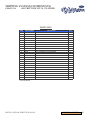
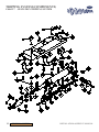
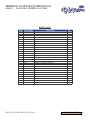
C50100TM
C50100TMK
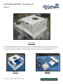
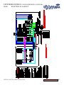
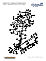
2” (50 SYSTEM) 1 HP W/ METAL COVER
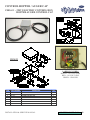
2” (50 SYSTEM) 1 HP W/ METAL COVER &
LIGHT KIT
FUNCTION
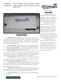
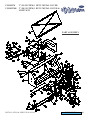
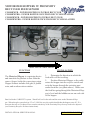
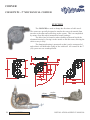
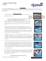
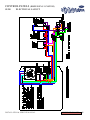
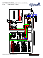
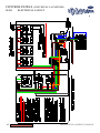
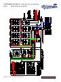
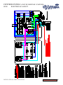
The Drive Unit is the
mechanism which pulls the cable
through the system. The cable is
pulled through the Drive Unit by a
sprocket driven by a 1 HP electric
power motor and Gear Reducer.
The cable enters the left
end of the Drive Unit, travels
around the sprocket and is picked
up by two Idler Wheels, which
guide it to the outlet on the right
end of the Drive Unit. The outgoing cable travels under the incoming cable, allowing material
INSTALLATION
brought into the Drive Unit to drop
onto the outgoing cable and be car1.
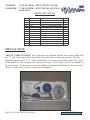
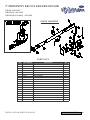
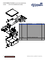
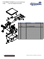
DETERMINE LOCATION: This Drive Unit can be located alried out returning it to the system.
most anywhere in the circuit, but if possible, it should be located inside the
One of the two Idler
building on the return line of the system. Consider ease of service when
Wheels is spring-loaded to act as
locating it, remembering that the cable travels from left to right and the
an automatic tensioning device,
sprocket turns counterclockwise.
removing slack from the cable. If
2.
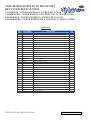
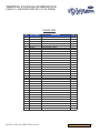
INSTALL PORT: Mount port (Item 28) to outlet on right end of the slack becomes excessive, or
the drive frame. Install breather in Gear Reducer by replacing top plug.
if the tension becomes too high, a
3.
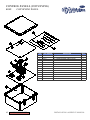
MOUNT DRIVE UNIT: Unit can be suspended from chains by
Drive Unit Safety (Roller) Switch
using eyebolts attached to mounting angle (Item 22).
will shut off the Drive Unit.
4.
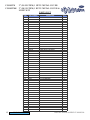
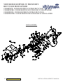
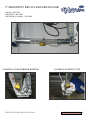
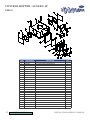
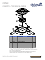
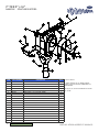
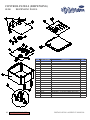
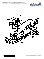
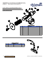
INSTALL MOTOR: Attach motor to motor base (Item 19) and secure pulley to motor shaft. Thread adjusting bolt (Item 49) through motor
base and into nut (Item 39). Attach this assembly to Drive Unit with pivot
rod (Item 20) and cotter pins (included in bag kit). (See figure A)
5.
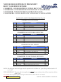
INSTALL BELT: Align belt by moving motor pulley. Check pulleys, make sure they are tight. Adjust belt tension (see page 4 for proper
tension) by moving the adjusting bolt (Item 49).
6.
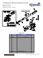
INSTALL BELT GUARD: Position belt guard (Item 12) in place
between the guard clip (Item 13) and the drive unit frame. Snap into place,
insert two #10 x 3/8” sheet metal screws (provided in bag kit) into belt
guard through drive unit frame.
7.
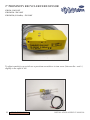
ELECTRICAL CONNECTION: Have qualified electrician wire
power supply to Drive Unit Safety Switch (Roller) (Item 57) and motor.
Check direction of motor, sprocket must turn counterclockwise.
8.
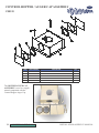
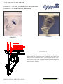
ATTACH COVER: Slip cover (Item 9) into place behind springcovers (Item 21).
13
DRIVE UNITS
INSTALLATION & SERVICE MANUAL