1
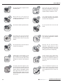
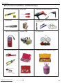
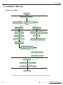
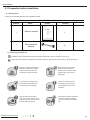
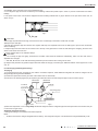
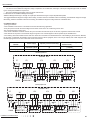
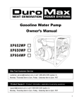
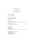
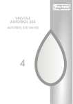
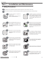
Service Manual
Part Ⅱ : Installation and Maintenance
7. Safety Precautions
Forbidden Items! It indicates that improper operation might lead to human casualty or sever injury.
Items need to be followed. It indicates that improper operation might lead to personal injury or property damage.
Follow this instruction to complete the
installation work.
Please carefully read this manual
before unit startup and service.
Installation should be conducted by
dealer or qualified personnel. Please
do not attempt to install the unit by
yourself. Improper handling may result
in water leakage, electric shock or fire
disaster etc.
Before installation,please check if the
power supply is in accordance with
the requirements specified on the
nameplate.And also take care of the
power safety.
Make sure the unit can be earthed
properly and soundly after plugging into
the socket so as to avoid electric shock.
Please do not connect the groundwire
to gas pipe, water pipe, lightning rod or
telephone line.
Be sure to use the excluxive
accessory and part to prevent the
water leakage,electric shock and fire
accidents.
exclusive
N2
Wire size of power cord should be large
enough The damaged power cord and
connection wire should be replaced by
exclusive cable.
Never fail to comply with the nitrigen
charge requirements. Charge nitrogen
when welding pipes.
Please firstly connect the wired
controller before energization,otherwise
wired controller can not be used.
Installation and Maintenance
If refrigerant leakage happens
during installation, please ventilate
immediately.Poisonous gas will emerge
if the refrigerant gas meets fire.
After connecting the power cord, please
fix the electric box cover properly in
order to avoid accident.
Never short-circuit or cancel the
pressure switch to prevent unit damage.
Before using the unit, please. check
if the piping and wiring are correct
to avoid water leakage, refrigerant
leakage,electric shock, or fire etc.
11
Service Manual
Do not insert fingers or objects into air
outlet/inlet grille.
Open the door and window and
keep good ventilation in the room to
avoid oxygen deficit when the gas/oil
supplied heating equipment is used.
Never start up or shut off the air
conditioner by means of directly plug
or unplug the power cord.
Turn off the unit after it runs at least
five minutes; otherwise it will influence
oil return of the compressor.
<5Min
Do not allow children operate this unit.
Do not operate this unit with wet
hands.
Turn off the unit or cut off the power
supply before cleaning the unit,
otherwise electric shock or injury may
happen.
Never spray or flush water towards
unit, otherwise malfunction or electric
shock may happen.
Do not expose the unit to the moist or
corrosive circumstances.
Electrify the unit 8 hours before
operation. Please switch on for 8
hours before operation.Do not cut off
the power when 24 hours short-time
halting (to protect the compressor).
24H
Volatile liquid, such as diluent or gas
will damage the unit appearance.
Only use soft cloth with a little neutral
detergent to clean the outer casing of
unit.
If anything abnormal happens (such
as burning smell), please power off
the unit and cut off the main power
supply, and then immediately contact
Gree appointed service center. If
abnormality keeps going, the unit
might be damaged and lead to electric
shock or fire.
12
30 C
26 C
Under cooling mode, please don't
set the room temperature too low
and keep the temperature difference
between indoor and outdoor unit
within 5OC.
User is not allowed to repair the unit.
Fault service may cause electric
shock or fire accidents.Please contact
Gree appointed service center for
help.
Installation and Maintenance
Service Manual
Main Tools for Installation and Maintenance
1. Level meter, measuring tape
2. Screw driver
3. Impact drill, drill head, electric drill
4. Electroprobe
5. Universal meter
6. Torque wrench, open-end wrench, inner
hexagon spanner
7. Electronic leakage detector
8. Vacuum pump
9. Pressure meter
10. Pipe pliers, pipe cutter
11. Pipe expander, pipe bender
12. Soldering appliance, refrigerant container
Installation and Maintenance
13
Service Manual
8. Installation Manual
Installation procedures
Start installation
Preparation before installation
Read the requirements
for electric connection
select installation
location
Select indoor unit
installation location
Prepare tools
Select outdoor unit
installation location
Install the support of outdoor unit
(select it according to the actual situation)
Install wall-mounting
frame, drill wall holes
Connect pipes of indoor
unit and drainage pipe
Fix outdoor unit
Connect wires of indoor unit
Install drainage joint of outdoor unit
(only for cooling and heating unit)
Bind up pipes and
hang the indoor unit
Make the bound pipes pass
through the wall hole and then
connect outdoor unit
Connect pipes of outdoor unit
Connect wires of outdoor unit
Neaten the pipes
Vacuum pumping and leakage detection
Check after installation and test operation
Finish installation
Note: this flow is only for reference; please find the more detailed installation steps in this section.
14
Installation and Maintenance
Service Manual
8.1 Preparation before Installation
8.1.1 Standard parts
Please use the following standard parts supplied by GREE.
Namber
1
2
name
Pars of Outdoor Unit
picture
Quantity
Owner’s manual
1
Tube connector
subassy
6
Remark
8.1.2 Selecting installation site
Forbidden Items! It indicates that improper operation might lead to human casualty or sever injury.
Items need to be followed. It indicates that improper operation might lead to personal injury or property damage.
Install the unit at a place where is
adequa to withstand the weight
of the unit and make sure the
unit would not shake or fall off.
Installation and Maintenance
Never expose the unit under
direct sunshine and rainful.
install the unit at a place where
is against dust, typhoon and
earthquake.
Try to keep the unit away from
combustible, inflammable and
corrosive gas or exhaust gas.
Leave some space for heat
exchanging and servicing so
as to guarantee unit normal
operation.
Keep the indoor and outdoor
units close to each other as much
units close to each other as much
the pipe length and bends.
Never allow children to approach
to the unit and take measures
to prevent children touching the
unit.
15
Service Manual
When the outdoor unit is totally surrounded by walls, the installation space of the unit should be as required in
Fig.1.
>1000
> 500
> 500
>500
>2000
>500
>2000
unit:mm
Fig.1
8.1.3 Piping Connection
The maximum pipe length is shown in the following table. When the distance between units (piping length) is out of the range listed below,
normal run of the unit can not be guaranteed.
M odel
Connecting Pipe ( mm )
M ax. Pipe lengt h( m )
L iqu id
Gas
GWHD(36)NK3J O
Ф 6.35
Φ 9.52
75
GWHD(42)NK3J O
Ф 6.35
Ф 9.52
75
M ax. Height D if f erence betw een
I ndoor Un it and Outdoor Un it ( m)
When the outdoor unit is above maximum
height difference between indoor and
outdoor units is up to 15m; When the indoor
unit is above,maximum height difference
between indoor and outdoor units is up to
15m.
Note:
① Use water-proof insulating pipe.
② Wall thickness of pipe: 0.5-1.0 mm;bearing pressure: 3.0MPa
③ The longer the connection pipe is, the more cooling and heating capacity will decrease.
16
Installation and Maintenance
Service Manual
8.2 Installation Instruction
90
350
1106
8.2.1 Outline and dimension of the outdoor unit
GWHD(36)NK3JO
Outline dimension andMounting holes
1080
631
282
440
401
194
Fig.2
90
450
1106
GWHD(42)NK3JO
Outline dimension andMounting holes
282
194
440
401
1080
631
Fig.3
Installation and Maintenance
17
Service Manual
8.2.2 Installation of the Connection Pipe
Connecting piping for indoor unit and outdoor unit are in manifold mode. (As shown below).
Fig.4
1) Piping between the Indoor and Outdoor Units
● If the liquid and gas stop valves which have the sign of A , B, C, D or E have not been connected to the indoor units, please turn off the
screw cap with the spanner airproof.
● Refer to Fig.5 for the moments of torque for tightening screws.
● Let the flare end of the copper pipe point at the screw and then tighten the screw by hand.
● After that, tighten the screw by the torque wrench unit it clatters (as shown in Fig.5).
● The bending degree of the pipe can not be too small; otherwise it will crack. And please use a pipe tube bender to bend the pipe.
● Wrap the exposed refrigerant pipe and the joints by sponge and then tighten them with the plastic tape.
Pipe
Spanner
Flare Nut
Pipe
Pipe
diameter
diameter(inch)
Φ6.35 mm
Φ6.35mm
Φ9.52mm
Φ9.52 mm
Φ12.7mm
Φ12.7 mm
Φ15.9mm
Φ15.9 mm
Thickness of
Thickness of
copper
tube
copper tube
Tightening
Tightening
torque
torque(ft·Ibf)
≥0.8
mm
≥0.8mm
≥0.8mm
mm
≥0.8
15̚30
15~30 N·m
N·m
N·m
3535~40
̚40 N·m
≥≥1.0mm
0.8mm
45̚50
60~65 N·m
N·m
≥0.8mm
≥1.0 mm
45~50 N·m
60̚65 N·m
Safety Precautions
Please read this manualFig.5
carefully before using and operating correctly as instructed in this manual.
Please especially take notice of the following two symbols:
CAUTION!
Warning! It indicates improper operation which will lead to human casualty or severe injury.
① . During the connection of the indoor unit and the refrigerant pipe, never pull any joints of the indoor unit by force;
Caution! It indicates improper operation which will lead to injury or property damage.
otherwise the capillary pipe or other pipe may crack, which then would result in leakage.
The refrigerant pipe should be supported by brackets, that is, don’t let the unit withstand the weight of it.
② .Warning!
installation
should besize
committed
to unit
the appointed
service
will of
cause
water
ƹ
If the
piping connection
of outdoor
does not match
thecenter;
piping otherwise
connectionit size
indoor
unit, use the piping
③ .The
connection dimension of indoor unit. And use different-diameter joints which is installing on the
place of the piping connection to connect the indoor unit.
ƹ Please install the unit in a place where is strong enough to withstand the weight of the unit; otherwise,
CAUTION!
the unit
would
and
causeeach
injury
or death.
● For
the fall
Freedown
Match
system,
pipe
should be labeled to tell which system it belongs to avoid mistaken inaccurate piping.
ƹ The drain pipe should be installed as instructed in the manual to guarantee the proper drainage;
meanwhile it should be insulated to prevent condensing; otherwise the improper installation would cause water
leakage and then wet the household wares in the room.
ƹ
ƹ Under the occurrence of an error (like burning smell etc.), please cut off the main power supply of the
unit.
use.
ƹ
ƹ
of
ƹ Please take notice of the supporting frame of the unit to see if it is damaged over the long time periodInstallation
and Maintenance
18
Service Manual
2) Allowable pipe length and drop height among indoor and outdoor units
If the total refrigerant pipe length (liquid pipe) is smaller than that listed in the table below, no additional refrigerant will be charged.
Model
GWHD(36)NK3JO
Total Liquid Pipe
GWHD(42)NK3JO
40
Lenght (a+b+c+d+e)
40
Allowable Length and Height Fall of the Refrigerant Pipe
Allowable Value
GWHD(36)NK3JO GWHD(42)NK3JO
Total length(actual length) of
fitting pipe
75m
75m
length of farthest fitting pipe(ft)
25m
25m
15m
15m
15m
15m
7.5m
7.5m
Outdoor unit
at upper
Outdoor unit
at lower
Height difference between
indoor units(ft)
Installation and Maintenance
Outdoor unit
Indoor unit
Height difference between
indoor units H2
Height difference between indoor unit and outdoor unit H1
Height difference
between outdoor
unit and indoor
unit
Fitting pipe
Equivalent length of the farthest fitting pipe Lx
L1
L2
a
b
Indoor unit
L3
L4
L5
c
d
e
Fig.6
19
Service Manual
3) Installation of the Protection Layer of the Refrigerant Pipe
a. The refrigerant pipe should be insulated by the insulating material and plastic tape in order to prevent condensation and water
leakage.
b. The joints of the indoor unit should be wrapped with the insulating material and no gap is allowed on the joint of the indoor unit, as
shown in Fig.7.
Safety Precautions
Please read this manual carefully before using and operating
Fig.7 correctly as instructed in this manual.
Please especially take notice of the following two symbols:
No gap
CAUTION! It indicates improper operation which will lead to human casualty or severe injury.
Warning!
After the pipe is protected well enough, never bend it to form a small angle; otherwise it would crack or break.
Caution! It indicates improper operation which will lead to injury or property damage.
4)Wrap the Pipe with Tape:
Warning!
a. Bundle the refrigerant pipe and electric wire together with tape, and separate them from the drain pipe to prevent the condensate
installation should be committed to the appointed service center; otherwise it will cause water
ƹ The
Safety
Precautions
water
overflowing.
Please
read
this from
manual
carefully
before
using
and
operating
correctly
as instructed
in wall.
this manual.
b. Wrap the pipe
the bottom
of the
outdoor
unit
to the
top of the
pipe where
it enters the
During the wrapping, the later circle
Please
especially
take
notice
of
the
following
two
symbols:
should
coverinstall
half ofthe
theunit
former
ƹ Please
in one.
a place where is strong enough to withstand the weight of the unit; otherwise,
c. Fix the wrapped pipe on the wall with clamps.
the unit would fall down and cause injury or death.
CAUTION!It indicates improper operation which will lead to human casualty or severe injury.
Warning!
drain
pipe
installed
as instructed
in the
manual
the proper drainage;
ƹ .The
Do not
wrap
the should
pipe toobe
tightly;
otherwise
the insulation
effect
would to
be guarantee
weakened. Additionally,
make sure the drain hose is
①
Caution! It indicates improper operation which will lead to injury or property damage.
meanwhile
it should
bepipe.
insulated to prevent condensing; otherwise the improper installation would cause water
separated
from the
Warning!
that, fill
thethe
hole
on the wallwares
with sealing
② .After
leakage
and then
wet
household
in the material
room. to prevent wind and rain coming into the room.
ƹ The installation should be committed to the appointed service center; otherwise it will cause water
(4)
ƹ Support and protection for pipeline Support should be made for hanging connection pipe. Distance between each support can not be
over 1m.
ƹ Under the occurrence of an error (like burning smell etc.), please cut off the main power supply of the
ƹ Please install the unit in a place where is strong enough to withstand the weight of the unit; otherwise,
unit. 8.2.3 Air Purging and Refrigerant Charge
the unit would fall down and cause injury or death.
ƹ
Air purging
ƹ The drain pipe should be installed as instructed in the manual to guarantee the proper drainage;
1)
ƹ The refrigerant has been charged into the outdoor unit before shipment, while additional refrigerant still need be charged into the
meanwhile
it shouldduring
be insulated
to prevent condensing; otherwise the improper installation would cause water
refrigerant
take noticethe
offield
the installation.
supporting frame of the unit to see if it is damaged over the long time period of
ƹ Pleasepipe
2) Check
if thewet
liquid
and the wares
gas valve
of the
outdoor unit are closed fully.
leakage
and then
thevalve
household
in the
room.
use. 3) As shown in the following figure (Fig.8), expel the gas inside the indoor unit and refrigerant pipe out by the vacuum pump.
ƹ
ƹ
Manometer
burning smellManometer
etc.), please cut off the main power supply of the
ƹ Under the occurrence of an error (like
or relocation of the unit.
unit.
are prohibited to dismantle the"HI"Knob
electric box owing to the high voltage of the
ƹ Non-professional personnel
"LO"Knob
ƹ
outdoor unit.
ƹ
liquid valve
An all-pole disconnection switch having a contact separation of at least
3mm in all poles should be
pumpover the long time period of
it is damaged
ƹ Please take notice of the supporting frame of the unit to see if Vacuuming
use.
ƹ
Caution!
or relocation
of the unit.
ƹ
are prohibited to dismantle the electric box owing to the high voltage of the
ƹ Non-professional
nameplate
and also checkpersonnel
its security.
Connection hose
outdoor
Before using the unit, please check if the piping and wiring are correct to avoid water leakage,
ƹ unit.
Fig.8
Gas
valve a contact separation
An all-pole disconnection switch
having
of at least 3mm in all poles should be
4) When the compressor is not running, charge the R410A refrigerant into the refrigerant pipe from the liquid valve of the outdoor unit (do
power
supply must be earthed to avoid the hazard of electric shock and never connect this
ƹ The
not
do it main
from the
gas valve).
earthAdditional
wire to therefrigerant
gas pipe, charging
running water pipe, lightening rod or phone cable’s earth lead.
Caution!
a.
ƹRefrigerant Charge in the Outdoor Unit before Shipment
ƹ
Notes:
ƹ Do not allow children operate this unit.
nameplate
and also
its security.
unitcheck
has been
charged refrigerant before delivery. The refrigerant charge is not included those charged additionally in the
① . Outdoor
ƹ Do not operate this unit with wet hands.
ƹ Before using the unit, please check if the piping and wiring are correct to avoid water leakage,
ƹ
ƹ When the unit is not to be used for a long time, please cut off the main power supply of the unit.
ƹ The main power supply must be earthed to avoid the hazard of electric shock and never connect this
ƹ Do not expose the unit to the moist or corrosive circumstances.
earth wire to the gas pipe, running water pipe, lightening rod or phone cable’s earth lead.
Installation and Maintenance
20
ƹ Never step on the unit or place any object on it.
ƹ
ƹ It is suggested to have a power-on test annually.
Service Manual
indoor unit and the refrigerant pipe.
② . The amount of the additional refrigerant charge is dependent on the diameter and length of the liquid refrigerant pipe which is decided
by the actual yield installation requirement.
③ . Record the additional refrigerant charge for future maintenance.
b. Calculation of the Additional Refrigerant Charge
Additional Refrigerant Charge=(ΣLength of Liquid Pipe Φ9.52X54+ΣLength of Liquid PipeΦ6.35X22)-880
The biggest additional refrigerant charge value is 800g. It means that if the calculated value exceed 800g, the additional refrigerant charge
takes 800g, while the calculated value less than 800g, the additional refrigerant charge takes the calculated value.
8.2.4 Electric Wiring
1) Wiring precautions
● The installation must be done in accordance with the national wiring regulations.
● Only the power cord with the rated voltage and exclusive circuit for the air conditioning can be used.
● Do not pull the power cord by force.
● The electric installation should be carried out by the technician as instructed by the loc al laws, regulations and also this manual.
● The diameter of the power cord should be large enough and once it is damaged it must be replaced by the dedicated one.
● The earthing should be reliable and the earth wire should be connected to the dedicated device of the building by the technician. Besides,
the air switch coupled with the leakage current protection switch must be equipped, which is of enough capacity and of both magnetic and
thermal tripping functions in case of the short circuit and overload.
Power Supply
Capacity of the air Switch(A)
GWHD(36)NK3JO
220-240V~,50Hz
GWHD(42)NK3JO
220-240V~,50Hz
32
32
Models
Recommended Cord(piecesx
sectional area)
3 x 4mm
2
3 x 4mm
2
GWHD(36)NK3JO
287'225 81,7
;7
/
1
1 1 / 1
32:(5
1 3(
1 ,1'225 81,7 $
1 1 3(
3(
;7
;7
;7
;7
3(
3(
1 ,1'225 81,7 %
1 ,1'225 81,7 &
,1'225 81,7 '
GWHD(42)NK3JO
287'225 81,7
;7
/
1
1 3(
/
1
32:(5
1 1 1 ,1'225 81,7 %
1 1 3(
3(
,1'225 81,7 $
Installation and Maintenance
1 ;7
;7
;7
;7
;7
,1'225 81,7 &
1 3(
3(
1 ,1'225 81,7 '
1 3(
,1'225 81,7 (
21
Service Manual
2) Earthing Requirements
● The air conditioner is classified into the Class I appliances, so its earthing must be reliable.
● The yellow-green line of the air conditioner is the earth line and can not be used for other purpose, cut off or fixed by the tapping screw;
otherwise it would cause the hazard of electric shock.
● The reliable earth terminal should be provided and the earth wire can not be connected to any of the following places.
① Running water pipe; ② Coal gas pipe; ③ Sewage pipe; ④ Other places where the professional personnel think unreliable.
3) Electrical Cable Connection Cautions!
① . The mistake connecting line will result in malfunction. After the electrical wiring working, ensure the wire between the connection
place and the fixed place has a certain freedom degree.
② . The connection piping and connection line of each indoor unit should connect well according to the instruction.
③ . The electric installation should be carried out by the technician as instructed by the local laws, regulations and also this manual.
④ . The installation location should be dry, and can't be expose in direct sunlight or strong breeze.
⑤ . Have to install a breaker in the circuit that can shut off the main power supply of the system. Besides, the air switch coupled with the
leakage current protection switch must be equipped.
4) Wiring of the Power Cord
① . Open the side plate.
② . Connect the power card to the terminals “L1”, “L2” and also the earthing bolt, and then connect the wiring terminals “N(1),2,3” of the
indoor unit to those of the outdoor unit correspondingly.
③ . Fix the power cord with wire clips.
Safety Precautions
④ . Let the power cord go through the rubber ring.
Please read this manual carefully before using and operating correctly as instructed in this manual.
cords oftake
partsnotice
of appliances
for outdoor
usesymbols:
shall not be lighter than polychloroprene sheathed flexible cord(code designation
⑤ .Supply
Please
especially
of the following
two
60245 IEC 57).
CAUTIONS!
Warning!
It indicates improper operation which will lead to human casualty or severe injury.
If the supply cord is damaged, it must be replaced by the manufacturer or its service agent or a similarly qualified person in order to avoid
Caution!
It
indicates improper operation which will lead to injury or property damage.
a hazard.
Warning!
ƹ The installation should be committed to the appointed service center; otherwise it will cause water
ƹ Please install the unit in a place where is strong enough to withstand the weight of the unit; otherwise,
the unit would fall down and cause injury or death.
ƹ The drain pipe should be installed as instructed in the manual to guarantee the proper drainage;
meanwhile it should be insulated to prevent condensing; otherwise the improper installation would cause water
leakage and then wet the household wares in the room.
ƹ
ƹ Under the occurrence of an error (like burning smell etc.), please cut off the main power supply of the
unit.
ƹ
ƹ
ƹ Please take notice of the supporting frame of the unit to see if it is damaged over the long time period of
use.
ƹ
or relocation of the unit.
ƹ Non-professional personnel are prohibited to dismantle the electric box owing to the high voltage of the
outdoor unit.
An all-pole disconnection switch having a contact separation of at least 3mm in all poles should be
Caution!
ƹ
nameplate and also check its security.
ƹ Before using the unit, please check if the piping and wiring are correct to avoid water leakage,
Installation and Maintenance
22
ƹ The main power supply must be earthed to avoid the hazard of electric shock and never connect this