1
Film-Tech
The information contained in this Adobe Acrobat pdf
file is provided at your own risk and good judgment.
These manuals are designed to facilitate the
exchange of information related to cinema
projection and film handling, with no warranties nor
obligations from the authors, for qualified field
service engineers.
If you are not a qualified technician, please make no
adjustments to anything you may read about in these
Adobe manual downloads.
www.film-tech.com
SEIYICE IffiTNUCTTOHS
AUTOTOAD@
l6mmPROJ[(TO
flt|tril0S0uND@
{AUT0ilATICTHRIADIilG}
M O DLES
1 5 8 5 CC
/H
I 585CH/CHS
I 585M1/MLS
15 9 0 c l C S
1592C/CS
15 9 2 C H I C H S
1978 BelI A Howell Company
All Riqbts reserved
BTLLEHBIUELL
DEPI.
INTERilATIOI{AL
SERUICE
pART N0. 7 4t+0U
M A Y1 9 7 8
t
I
I
L
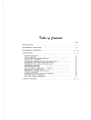
7d1r& o/ (/ar€"do
Page
I
TNTRODUCTTON
1 - 3
DISA.SS
EMBLY PROCEDURE
4-9
REA,SSEMBLYPROCEDURE . .
10-20
AE};ruSTMENTS
...
2L-34
General Instnrctions
Optical Alignment
AdJusting the Interrnittent Mechanism . . Lens Carrier Adjustment
Adjusting the Animation Clutch (1592 Models Only) .
Adjusting the Fire Shutter (1592 Models Ody) .
Adjusting the Reel Arrns and Rewind Clutch
Adjusting tbe Soundhead
Projector Speed Checks
Auto-Load System djqstments - General
Adjusting the Loading Guides
Checking and Adjusdng Loop Restorer
Ttming ttre Sprockets
Cbecking the Exciter Lamp Cover Clearance
Gear Sbift ?ension Adjustment
Idler Gear Backlash Adjusfuient
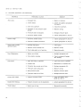
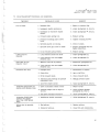
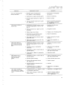
TROUBLE SIIOOTING
I
I
j
2L
,,
,.t
25
26
27
27
27
29
30
30
32
34
34
34
34
35-43
-
a
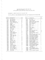
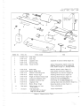
RECOMMENDED SPARE PARTS LIST FOR
AUToLoAD@FILMosouNo@:.0ltru PRoiEcr oR MoDEL 1592c
REFERENCE:
SERVICE MANUAL
NO. ?4404 MAY 19?8
THE FOLLO'vVING Ift A RECOMMENDED SPARE PARTS LIST FOR REPAIR OF 50 PROIECTOF.S.
PART NO.
DESCRIPTION
17639
2L736
24047
30166
30811
31011
31135
3L237
31239
3L24L
3L245
31557
31561
33385
34766
34878
34884
34889
35814
35830
35846
35850
3601S
36014
36015
36018
36038
36047
36064
36065
36083
36?69
367?1
36999
37293
37302
37302
41307
+4372
44370
4437L
Ring, Retaining
Ring, Retaining
.
Belt, Take-up
Screw, Binding head
Screw. Hex washer head
Bearing
Spring
Washer, Nylon
Gear, Spur
Clip, Retaining
Ring, Retaining
Shuttle
Foot,Rubber...
Gear, Spur.
Bar, Tilt
Washer
Lamp, Exciter
Screw, Binding head
Guard, Sprocket
Spring
Guide, Upper arm
Guide, Lower arm
Wiper, Felt . .
Wick, Cam
Spring
Spring, Leaf
Spring
Follower, Cam .
Rail, Film guide
Shaft, Cam
Ring, Retaining . .
Setscrew
Setscrew
Guard, Sprocket
Rail, Film tension
Pawl, Locking
Shaft, Locking pawi
Cam. Pull down .
Key, Gear retaining
Gear, Spur
Gear, Spur
PART NO.
L2
44459
45682
45692
47431
49532
49696
49945
308638
Belt. Drive
Cover, Rear atm
Capacitor, Start. .
Lamp, Projector (EKS-EMM).
Shaft, Rear reel atm
Cover, Front arm
Switch, Rotary
Fuse .
o
707013
707110
707LLZ
7072J-L
7O728L
107741
708246
76577i
99828
05712
0980?
09828
01L214
0LL22L
011235
011236
012132
012133
012134
013946
014536
014558
0145?3
014575
014947
014949
015569
Knob. Control. . .
Geer .
Gear, Clutch
Spring, Tension
Capacitor
Speaker
.
Screw, Hex washer head
Ring, Retaining
Ring, Retaining .
Bearing Assembly, Support.
Knob, Tilt
Contact Assembly, Exciter lamp
Shaft and Liok Assembly
Lever and Pi.vot Assembly
Bearing and Arm Assembly. .
h-Out Bracket Assembly . .
Plate Assembly, Aperture . .
.
Plate Assembly, Kick
Hub and Bracket Assembly
SprocketAssembly
Sprocket Assembly, Upper
SolenoidAssemblv
2
3
3
6
2
2
Lz
12
12
2
2
2
2
2
2
2
1
2
2
2
,
1
2
0155?3
015919
016394
016495
016530
Motor Assembly. . .
Clutch Assembly, Rewind. .
Clutch and Bearing Assembly.
Motor .
P. C. B. Amplifier AssemblY
12
. .
QTY
DESCRIPTION
QTY
L2
24
L2
o
t2
L2
L2
L2
1'
5
6
1
t2
L2
L2
L2
J
.t
L2
t2
12
T2
L2
L2
.t
2
t2
,4.
24
a
3
3
2
e
L2
a
3
Switch Assembly, Animated
Lampholder Assembly
Gear and Bearing Assembly.
Clutch Assembly, Take-up
Photocell and Lite Pipe
Assembly
z
3
t2
2
2
o
q
3
.
o
I
2
i€1
C T OR S
F I L M O S O U N DR* O
PJE
1 5 8 5, I 5 9 0 , 1 5 9 2
M0DELS
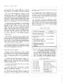
?afnodzAaaa
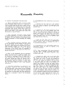
GENERAL.
This Service lWanual has been prepared to assist
of Bell & Howell
and adjustment
in the repair
Threading 16mm Sound ProCompany Automatic
jectors, Models 1585, 1590 and 1592. Design speciList
fications are listed in the Feature Description
Parts Catalog
on the preceding page. .{n illustrated
is included at the rear of the manual to identify
parts and to aid the serviceman in
replacement
the disassembly and reassembly of the projector.
DESCRIPTION.
With the exception of the 1585ML and MI-S, all
projectors
eovered in these instructions are ttCrr
versions of the basic proiector models (1585C, 1590C
suffix letters are used
and 1592C). The additional
to identify variations of tbe basic models, as follows.
The suifix letter t'Srr signifies a basic ilCrr o!
ML model equipped with a front eover and speaker
(Parts
15) rather than
Catalog Figure
assembly
the standard front cover (Parts Catalog Figure 1,
item 1).
The sqffix letter H signifies a basic "Crr model
wired for' 50/60H2 operation rather than 60Hz only.
The Models 1585ML and IVILS are militarized
*rersions of the 1585CH and CHS and also are designed for 50/60H2 operation.
the CS, CH,
Except for the above variations,
CHS, ML and MI-S versions are identical with the
basic rrCt? models and almost all components are
The most notable physical differinterehangeable.
ence in the 1585 models are the ML and MLIi projectors,
the top covers of which are provided w'ith
two five amp Slo-blo fuses. Part number differences between models are indicated by the use of
in the "Usable on Code" column of
code letters
The coding system is explained
the parts lists.
on page 2 of the Parts Catalog. AU models are
equipped with a ls-watt amplifier.
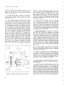
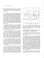
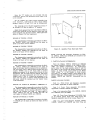
Only the 1592 models are equipped with the rrstilllr
picture control and animation feature. The Etep-bystep motion is accomplished by placing the rrRun-Still't
control knob in the rrstillrf position and the "Motoror
Lampt' switeh in either the '?Forward-Lamp'
"Reverse-Lamp"
position; then depressing the animation lever at the top of the mechanism housing.
The film will advanee frame by frame each time the
lever is depressed and released. If the lever is held
down, the frames will continue to advance insequence
(for the animation effect) until the lever is released.
These 16mm sound projectors are completely
gear driven, with shifting from forward to rewind
accomplished by means of a rocker plate/idler gear
amangement. The autoload system consists of a s eries
of guides, loopformers and roilers which, when the
system is in the rrloadtf position (closed), will guide
the film through the tlrreading path to thefilm take-up
reel. lVhen the system is in the "open" position, the
guides and rollers clear the film path.
TTre upper and lower guides are connected by a
mechanical iinkage with a locking lever at the lower
end to actuate (close) the system. -{.film escapemechanism ls included at the upper end of tbe linkage to
prevent damage to the film due to jamming, When a
film jam occurs, the filmwillfoldandflow out through
the kickplate of the escape mechanism until the operator has had an opportunity to stop the projector.
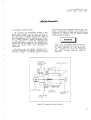
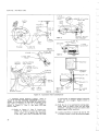
SPECIAL }IAINTENANCE PRECAUTIONS.
The removal and installation of most projector parts can be accomplished $tith tools normally
available in photo equipment repair shops. A penciltype soldering gun should be available for electrical repairs, and the Bristol wrenches listed in
tie following chart will also be required. Special
tools and gages necessary for projector alignments
and adjustments are illustrateci and listed in Figure A and its accompanying chart.
BruSTOL SETSCREWWBENCHESREQUIRED
FOR MAINTENANCE
B&H Part No.
SetscrewSize
No. of
Flutes
Ilandle
Wrench
No. 4-40
o
G12?1-F1
G127r.-X2
No. 6-32
o
sTK3852-B
sTK386S-B
'No. 8-32
6
G165-F1
G165-X2
NOTE: Wreneh G165-Fi is neededtt tighten
setscrew in tool handles.
CLEANING.
All film path areas must be kept free from
emulsion build-up, or film jamming will take place
during the automatic threading operation. Use Toluol,
and,/or an orange stick to femove emulsion from
S ER VI C E I N S TR U C TI O N S
the fiim path areas, being careful not to scratch
the surfaces. Pay particular attention to the film
path parts of ihe soundhead cover and soundhead.
Do not use trichloroethylene solvents to elean
plastic parts. Use a naphtha base cleaning fluid and
be sure that grease is NOT wiped off critical areas
of lubrication. Do not use solvents on these critical
areas, especially in the auto-threading linkage, since
lubrication is applied during assembly and it would
be difficuit to replace without disassembling the linkage. Use a soft lint free eloth when necessaryto
r€move any accumulation of dust or film chips.
puring periodic maintenance of the projector,
thd transport mechanism should be removed and
thoroughly cleaned. Brush or blow out all large
particles of di.rt. Wash all moving parts except
ttOliteil bearings with any good petroleum solvent.
Wash "OliteI bearings and the pull-down cams with
naphtha. Wasb the cam oilers in naphtha, and replace if not thoroughly cleaned by washing. Discard
and replace the cam wiper and cam wiper wick.
As soon as parts have been washed and dried,
coat with a light fiim of the speci.fied lubricant.
LUBRICATION.
The fol.lowing Lubrication Chart lists those items
q'hich are to be lubrieated during reassembly" Lubricants specified can be ordered from Bell & Howell
by part number. Be careful not to over-lubricate. A
drop or two of oil and a light film of €rrease {appiied
with a bmsh, if possible) will be adequate. Wipe away
excess lubricant with a lint-free cloth.
Felt pads and wicks should be placed in a shallow
pan of the specified gr€ase or oil andallowed to stand
until saturated. Permit the excess lubricant to drain
away before installing these felt parts.
DBIVE BELT NEPLACEMENT
Because of the eompactness of design of these
projectors, the drive belt is not easily accessible
for replacement. To avoid extensive disassembly
at the rear of the projector, the following procedure is recommended. Refer to Parts Catalog Figure 2.
a. Remove the rear cover (item 7, Figure 1) to
expose the drive belt and associated components.
Manually run the drive belt off of the large mechanism pulley and pull the free end of tlre belt
from the belt shifter loop.
b. Remove the tie strips from around the wiring
at both ends of the motor.
c. Loosen the screws in both motor bracket
straps (28, Figure 3) and lift off the straps and
stabilizer bracket (29) as a group.
d. Raise the motor just enough to pernit the
belt to be passed beneath the moto! teward the
transformer. Be very careful not to lilt the motor
2
so high as to damage the blower fan at the end of
the motor shaft.
e. Disconnect tbe push-on connectors which conneet the motor leads to the starting capacitor (item
7C, Figrre 2) and r€move the crimp-tyrye solderless
connector which joins the grey-yellow motor lead
to the three white leads. The belt ean now be removed from the projector.
f. Install the new belt by reversing the above
order of removal. Replace the erimp-tlrye solderless connector with a screw-on qrye connector and"
wherr securing the motor *ith the motor bracket
straps, make sure that the motor grounding strap
(left end of motor) bears on the motor mounting
bracket (28, Figure 3).
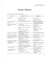
LUBRICA?ION CIIART
Parts to be Lubricated
Lubricant
Macb.inedsur{aces (nonbearing) of all castings
Oil (P/N 070003)
Sprocket shafts (17 and 19,
Figure 10)
Oit (P/N 08963)
Framer shaft (26, Figure
Oil (P/N 049?8)
12) and bearing face of
worm gear (24, I'igure 13)
Felt oil pads in cams, and
sliding parts (friction
surfaces; not otherwise
specified
Oil (P/N 070032)
The worm gear teeth and sprocket gear teetb
ale to be lubricated with special grease P/N
The followitg items are to be lubricated witb general purpoee grease P/N 070034:
All other gear and pinion teetb; all bearings
and pivot posts; reel arm lock buttons; all
shafts; cam w'iper and wick. gpecific instructions are noted in the reaesemblv section.
TEST FILM CIIART
TFIr55-NX1
C€ntering and framing loop
TFL-3?-NX1
Buzz track loop
TFL-26-NXB
TKHz azimuth loop
TFl'z3-lfr(l
400H2 power output loop
TFR-D550-NX5
Audio-Center-Framing roll
TFS-D550-N)(1
Loop restorer strip
(bad holes)
TFS-D550-NX5
Ioop restorer strip
(elongated holes)
F I L M O S O U NPDR O J E C T O R S
t 4 0 D E L1
S5 6 5 , 1 5 9 0 , 1 5 9 2
A*
/in
R E M O VI /EI 5 "
F R O MU P P E R
G U I D EB A R
SPRING
P/N 5124
3/4"
N
N,
,99999i
'@
n
t
<r\
| \,,, I
fr-t
l.l |
l i l /
t0
/
X/
INDEX NO.
\4r'
,-
f\,4
\/A
SEEI NSET
ABOVE
l
T,t
TOOL NO.
TOOL NAME
s - 1 5 5 2 - 1 - N 1 Iamp Plug
2
s-5.50-2-N1
I-ens Plug
a
s-550-2-N2
Alignment
4
s-550-2-N3
Aperture
Make in Shop
Torque Wrench
Adjust rewind torque (check torque with
Clratillon #LP-72 (0 to ?2 oz.) push-pull
scale, lvlaster Gauge Co., Chicago 606221
6
s-550-5-N2
Sttoke Gage
,7
s-09?01-35N2 Shuttle Height Gage
Measure shuttle stroke (Figure F)
Check shuttle protrusion (Figure G)
8
s-552-2-N1
Restorer
q
s-552-4-Nl
Struttle Tension Gage
Adjusting shuttle tension (Figure II)
10
s-552-4-N2
Weigbt for Shuttle Tension Gage
Adjusting shuttle tension (Figure H)
11
s-552-1-N1
Timing and Alignment
t2
s-552-5-Nl
Soundhead Iocating
Timing the sprockets (Figure R)
Positioning the soundhead (Figure M)
s-550-8-N1
Alignment
s-550-5-N1
Struttle Stroke Target
Measuring shuttle stroke (Figrre J)
Shopmade
ftwind torque reel (use
P/N 0145?0)
Torque adjustments
Purchase
Push-Pull Scale
(chatillon #LP -7 2 (Master
Gage C0, Chicago 60622
Torque adjustments
13
Alignment of opticai system (Figure E).
Rod
Plug
Positioning
Tool
Plate
Gage
Tool
Adjusting the loop restorer (Figure R)
Aligning sound drum and photocell (Figure L)
Figure -{. Special Service Tools
S ER VI C E I N S TR U C TI O N S
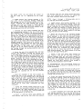
Dcpaaa*nfil? ?z'oeedazE
1. GENERAL PRECAUTIONS.
a. Be gure to use the proper size tools for disaesembly and reassembly procedures. After removing attaching parts (screws, nuts, etc.), loosely reinstall ttrese parts to the removed part or tapped
holes to prevent loss.
b. Cemented or adhesive backed parts aresonoted
in tbe pafis lists and can be removed by prying up
one edge with a lcrife blade" Be careful not to scratch
surrounding aleas, and remove traces of old adhesive with solvent.
c, When unsoldering is required to remove electrical parts, it is advisable to tag leadwires or make
a rough sketch of leadwire connections to facilitate
installation of ttre parts. Unsolder leads vrit} a pencil tJrye soldering gun, using a heat sink if available"
or gripping the lead with a pliers to provide additional heat dissipation.
d. When removing riveted parts for replacement,
the old rivet must be drilled out with a drill equal to, or
slightly smaller thean, the diameter of rivet to be installed. Refer to parts list6 for the rivet diameter.
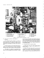
2. REMOVAL OF COVERS (Figure 1). Remove the
parts, aa trecessaly, in their indexed order of disassembly, noting tbe foliowing special precautions.
NOTE: The CS, CHS and MLS models are equipped
with a front cover and speaker assembly (Parts
Catalog Figure 15) rather than tbe standard front
cover (item 1, Parts Catalog Figure 1).
a. Unlatch and remove tbe front cover assembly
(1). If latches are to be replaced, the rivets (18)
must be carefully drilled out.
b. The rear cover (?) is secured by seven screws
(6) and (6,4'), three along the bottom edge and two
at each side. Use a thin-wall socket wrench to remove these screws, grinding it down if necessary,
so that it can fully engage the screw heads.
c. Remove two screws (8) near the top of the
mainplate to free top cover assembly (9). Remove
the four screws (9A) and disassemble the carying
handle (98) and brackets (9C) from the cover.
NOTE: The 1585ML and MLS are equipped with
two additional fuses (9D) which are mounted.in the
top cover assembly.
d. Remove three screws (11) and (12) and disassemble the lamphouse assembly (13) from the mainplate. The lower screw also attaches the airdeflector
A
(14). Tbe Still/Run knob (13F) is used only on the
1592 models" The lower end of the still-run lever engages the pin on the crank lever (item 11A, Figure 2).
3" REMOVAL OF END CAPS AND LAMP (Figure 2).
Remove parts, as necessary, in their indexed order
of disassembly, noting the following special precautions.
a. Loosen the setscrew (1) and disassemble tlre
tilt knob assembly (2) from the tilt shaft.
b. Replacement of the speaker (68), starting capacitor (7C) and receptacle (7F) can be accomplished
without disassembling the end caps (6) and (7) from
the projector. However" iJ the end caps are damaged
and in need of replacement, proceed as follows:
Tilt the projector so tbat the four screws (3) and
one specer (3A) wbich secure the end caps (6) and
(?) to the base can be removed. Ttren set the Ptojector uprigbt a.ndremove the remaining four screws
(4) which are inserted through tlte front side of the
mainplate. Be careful not to lose the speed nuts (5)
assembled to the mounting boEses of the end caps.
c. flre 1592 models use a single knob (1.1) for
rrFwd-Rev-Lamptt control plus a crank lever (11A)
to provide for the ttStill,/Runrr eontrol operation.
d" To remove tbe projectioa lamp (12), press
down the lamp retaining spring and puil the lamp
straight out from its socket. Do not rock or twist
tlre lamp during removal" or the lamp pins may be
damaged. The lamp shield (14) and lampholder (15)
are secured ts the mainplate with two screws (13).
4. REMOVAL OF ELECTRICAL PARTS (Figure 3).
B efore removing electrical components, note the rnanner in wtrich tlre leadwires are routed and tied. The
pictorial wiring diagrams at the rear of the Parts
Catalog will assist in tbe proper reconnection of
ieadwires.
a. 1585 and 1592 Models Onlv. If only the power
transformer (4) is to be replaced, remove the two
hex nuts (1), screws (2) and lockwashers (3) at the
upper ends of the brackets (7) and (8). Export models
also require spacers (3A) which are located between
the bracket (8), brace (8A) and transformer. If the
lamp transformer (10E) is to be replaced, the entire
transformer group (items 1 through 10) must be
removed from the base. In order to gain access to
the two screws (9A), the amplifier cover (item 16,
Figure 6) must also be removed.
6\
F I L M OO
SU N D " P R O J E C T O R
M o D E L1S5 8 5 , 1 5 9 0 ,1 5 9 2
are
projeetors
These
b. 1590 Models Onlv.
(14) which
equipped wlth only a power transformer
is s&ured to the base with four screws (13). The
mounting brackets (14C) and (14D) can be replaced
by drilling out the rivets (14A). However, if the
itself is faulty, replace the complete
tiansformer
transformer and bracket assembly (14).
c" The drive motor and blower comporlents must
be removed as a unit to permit belt replacement or
motor and blower repairs. This is acccmplished b;r
removing the four motor mounting screws (15) and
the four blower housing screws (16). If tlle drive belt
(23) is in need of replacement, it can be cut with a
sharp knife. If the belt is in good condition, slip it
edgewise down between the mechanism pulley and
the casting. Lift the assembled motor and blower
from the base. Remove three screws (17) and disassemble the fan housing (19) from the housing cover
(22). Loosen the setscrew (20) and disassemble the
fan and hub assembiy (21) and cover (22) from t$e
motor sha-ft.
d, Loosen the screws in the top ears of the motor
clamps (28) and disassemble the clamps andmounting
(30) from the motor end bells. Note the
brackets
difference in motor clamp brackets (29) as used in
earlier models and in the more current designs,
thermal
urs well asr the addition of tbe coil-like
fuse (29A).
e. 1592 Models Only. Remove the twoscrews (33)
and disassemble the arimation switch and bracket
assembly (34) and rotary switch and bracket assembly (35) from the projector mainplate. Disassemble
as necessary, for repair or parts replacement.
f. 1585 snd 1590 lvlodels Onlv. Remove the nut
(36), lockwasher (3?) and rotary switch (3E) from
the mainpiate. Remove the screw (40) and the fuseholder (41).
5. REMOVAL OF GE.{RS, REEL ARUI.SAND SOUNDHEAD (FigUte 4). Remove parts, as necessary, in
their indsced order of disassembly, noting the following special Precautions.
a. To remove the rear reel artn assembly (29)
for repair or replacement, disassemble the retaining
ring (1), washer (3), spur gear (4) and a second retaining ring (1) from the end of the reel arrn shaft.
Note the matrner ln which the reel arm disc (27) is
positioned before disassembling.the screws (26) and
disc (2?) from the mainplate; ttren carefully withdraw the reel arrn assembly, catching the lock button
(30) and spring (3f) as they pop free.
b. To remove the front reel atm assembly (28)
for repair or replacement, disassemble the gear
and clutch parts (15) through (19) from the end of
the reel arm shaft. Note the manner in which tlre
reel artn disc (27) is positioned before disassemtrling
the screws (26) and disc (2?) from the mainplate'
Carefully withdraw the reel arm assembly' catching
the locK button (30) and spring (31) as they pop free'
c. To remove the soundhead assembly (40) for
repair or replacement, it first is necessary to remove the amplifier cover (item 16, Fig:r.re6) so that
the soundhead leads can be unsoldered from the edge
connector terminals (refer to appropriate wiring diagram). Assuming that the transformer assembly has
already been removed (paragraph 4), referto Figure4
and disassemble the retaining ring (32), flywheel (35)
and washers (33) and (34) from the end of the sound
dnrm shaft. Then remove three screws (36) and
washers (37) and carefully lift the soundhead assembly from the mainplate.
d. No special instructions are requlred for removal of the drive gearing in Figure 4 except to
note in which direction the gear hubs are facing'
Inspect all gears for chipped or broken teeth and
if iecessary. Clean and re-lubricate all
""pi.""
reusable gears6. REMOVAL OF RUN-STILL LINKAGE AND \TECHANISM A,SSEMBLY (Figure 5)' Remove parts'
as necessar-v, in their indexed order of disassembly,
noting the following special precautions'
NOTE: The disassembly procedures in steps a
througb d, following apply only to tlre 1592 model
projeitors. Steps e and f appiy to all models'
a. Loosen the setscrews (1) in the collars (2);
then disengage the lower end of the still-run rod
(4) from tfre pivoUng linli assemblv (18) and disessemble the rod, collars and spring (3) from the
stop pawl.
b. Loosen the setscrew (5) and remove the collar
(6) and spring (7) from the lower end of the fi.re shutter rod, Disengage the upper end of the rod from the
fire shutter and remove the rod (8).
c. Disassemble the still-run
mainplate.
lever (9) from the
d. Remove the two shoulder screws (12) and lift
the sliding link assembly (13) and the fwo spacers
(14) from the mainplate- Rpmove the pivot screw
and disassemble the pivoting link assembly
ifSl
(18), spacer (19), torsion spring (20) and flat washer
(21) from the mainPlate.
e. Remove two retaining rings (22) and lift out
the torsion spring (23). Remove the shoulder studs
(24), belt shifter bracket (25) and thq spacers (26)'
f. I{oId the mechanism assembly (29) securely
while removing the four screws (27) and the idler
gear adjustment bracket (28). Carefully withdraw the
mechanism assembly from the mainplate.
7. REMOVAL OF BASE COMP()NENTS(Figure 6).
Hemove parts, as necessary, in theil indexed order
of disaisembty, noting the following special precautions.
a. The lever stop and pin (5) has been carefully
adjusted to insure the proper advance of film and
S ER VI C E I N S TR U C TI O N S
then secured with screw (4). Do not disturb these
items unless obvious damage indicates a need for
replacement.
9. DISASSEMBLINGTHE REAR REEL ARM (Figure
8). Disassemble the rear r.eel arm in the following
manner, noting any special precautions.
b. Remove the adapter shaft (7) and lift out the
film guide roller (8). Remove the scr.ew (9) and lift
tlte sliding film guide assembly (10) from the flanges
on tbe base. Disassemble, if necessary, for replacement of damaged parts.
a. Remove the two scl€ws (1) and lift the reel
arm cover (2) from the rear arm (32). Note the shim
washers (3) located between the cover and the reel
arrn mounting bosses.
c. To expose the amplifier assembly (20) and
edge connector assembly (18), r€move thefivescrews
(15) and the cover (16). Remove the four screws
(17) and (19) and lift out both assemblies. When
separating the edge connector from the amplifier
pull them straight apart witbout wriggling or twisting them and thus distorting the pins. Note the
spacers (21) iocated beneath tJreamplifier.
b. Press the take-up atm against the reel arm
casting and slip the take-up beit (4) from the pulleys.
Release the take-up arm slowly and catch the tension
lpring (5) as it drops free. Remove the screw (6) and
disassemble the take-up spindle and pulley assembly
(7) and shim washer (8) from the take-up arm.
The take-up arm and rear reel arrn are replaceable only as .ul assembly (82).
d. Remove the four screws (22) and the cover
(23) to expose the volume and tone control assembly (25). Four screws (24) secure the control
assembiy into the base.
e. Remove the screw (26) and lockrvasher (27)
and disassemble the tilt bar (28) from the lower
end of the tilt gear rack (39). Remove two screws
(37) and disassemble the adapter (38) and gear rack
(39) from the base. Remove the retaining ring (40)
and lift out the tilt gearshaft (41) and spring tension
washer (42). Drive out the spring pin (43) aad iift
out the tilt wortn gear (44).
8. DISASSEMBLINGTHE FRONT REEL ARM (Figure 7). Disassemble the front reel arm in the folIowing manner, noting any special precautions.
a. Remove the two screws (1) and lift the reel
arrn cover (2) from the front ann (221" Note the shim
washers (3) located between the cover and reel arm
rnounting bosses.
b. Remove the screw (4) and disassemble the
feed spindle assembly (5) from the front reel arm.
If spindle parts are damaged, Ioosen the setscrews
(5A) and remove the gear (58) and washer (5C) from
the spindle (5D).
c. Remove the retaining ring (7) from the spring
post in the reel arm to free the end of the torsion
spring (10). Loosen the setscrews (8) and (8A) and
lift the gear (9) and torsion spring (10) drom tlre
reel arrn shaft (14). If damaged, disassemble the
plastic sleeve (9A) from tl1e gear hub.
d. Remove t}te two retaining rings (11) and <iisassemble the reel arm shaft (14) and washeirs (12)
and (13) from the rreel artn.
e. Remove the retaining ring (15) and withdraw
the upper spur gear (16) from the gearshaft (20).
Remove the two gear r€taining clips (17), the washer
(18) and the lower spur gear (f9) and slide the gearshaft (20) from the bearing posts of the reel arm.
lrspect the nylon bearings (21) and, if damaged,press
them from the bearing posts.
b
c. Remove the retaining ring (10) and large flat
washer (11) from the end of the gearshaft (16). Remove the rubber sleeve (12) from the hub of the gear
(14). Loosen the gear setscrew (13) and disassemble
tlle gear (14), the shim washer (1S) and the gearshaft
(16) from the reel arm.
d. Remove the retaining ring (l?) from the spring
post in the reel arTn to free the end of the torsion
spring (18) and lift the torsion spring from the hub
of the upper face gear (2?).
e. Remove the retaini.ng ring (19) and slide the
uPper sprrr gear (20) toward the upper face gear
(27) until the upper gear r€taining clip (21) can te
removed. Move the gearshaft (24) down until tlte upper spur gear (20) and washer (23) can be removed.
Remove the lower gear retaining clip (21) and lower
spur gear (22), and slide the gearshaft (24) from the
bearing posts of the reel arm. Inspect the nvlon
bearings
(25) and" if damaged, priss them from
the bearing posts.
f. Loosen the setscrew (26) and lift the upper
face gear (27) from the reel arm shaft (91). Remove tbe retaining ring (2E) and disaseemble the
reel arm sbaft (31) and washer {29) from the reel
arm.
10. DISASSEMBLINGTHE EXCITER LAMP COVER
AND SOUNDIIEAD (Figure 9). Disassemble the exciter lamp cover and soundhead assembly in the following marner, noting any special precautions.
a. hspect exciter lamp cover parts (1 through ?)
and disassemble only as necessary for replacement.
b" Make a careful note of leadwire connectionsbefore disconnecting or ursoldering leads during disassembly of the soundhead. Bemove the exciter lamp (8),
wipe off fingerprints, and wrap the lamp in tissue
paper.
c. Do not loosen the clamping screw (10) or disturb the lateral position of tlre optical slit assembly
{11) unless it has been deterrnined that the optical
slit is in need of replacement or adjustment.
6\
RO..tE
Ct0RS
F I LMoS
0UNO*p
M O D E L1S5 8 5 , 15 9 0 , 1 5 9 2
d. Unhook and remove the stabilizer arm spring
(12). Remove the r€taining ring (13) and disassemble
the roller adjusting screw (14) and complete stabilizer artn assembly (15) from the soundheadcasting.
Remove the two screws (15A) and washers (15B) and
disassemble the rollers (15C) and (15D) from t&e
stabilizer arm roller shafts. The removal of screws
(15E) will free the torsion spring (f5G) and stabilizer
auns (15F), (15H)and (15J).
e. Remove two scr€ws (16) and disassemble the
lamp contact assembly (1?) and lamp release ring
(18) from the soundheadcasting'
f. Loosen the setscrew (19) which bears against
the light pipe and photocell retainer (22). Then remove the two scr€ws (20), and carefully withdraw
the sound drum assembly (21), retainer (22) and
photocell assembly (23) as a group from the soundhead casting. Wrap the sound drum and photocell in
tissue paper to protect them from damage. Do not
remove the edge guide qcrew (24).
e. Whenremoving sprocket guards (27) and (28),
note the manner in which the torsion springs (30)
are assembled so that they may be properly reinstalled.
f.. L592 Models Og[. Loosen the setscrerv (34)
ana ffioiffi6Eimation
switch lever assembly (35) and switch lever crank (37) from the mechanism housing. Note: in Models 1585 and 1590, the
crank opening in the housing is sealed with a plug
(38).
12. DISASSEMBLINGTHE MECIIANISM (Figure 11).
Remove parts, as necessary, in their indexed order
of disassembly, noting the following special precautions.
a. Remove the three screws (1) andflangedrollers
(2). Note the manner in which the torsion spring (5)
is installed. Rpmove the retai.ning ring (3) and withdraw the threading arm (4) and torsion spring (5)
from' the mounting posts of the gu.ard mounting
plates.
g, To remove the stabilizer tension adjuster,
remove the retainins ring (25) from the adjuster
(27), and unscrew the adjuster from the tapped
hole in the spring r€tainer (28). Be car€ful not to
lose the friction washer (26) located at the lower
end of the adjuster.
b. Note the manner in which tlte legs of the torsion
spring (14) are engaged. Remove the serew (6),
idler
roller (7), roller stud (8), locking lever
eccentric (9), torsion spring (10) and autothr€ad
lever assembly (11).
11. DISASSEMBLINGTHE MECHANISM (Figure 10).
Remove parts, as, necessary, in their indexed ortier
of disassembly, noting t}te following special precautions.
c. Note the manner in which the legs of tlre torsion spring (14) are engaged. Remove the retaining
ring (12) and lift off the lower loopfo::rrer (13) and
torsion spring (14).
a. To remove the lens carrier assembly (5), pry
out the hinge pins (1) and (2) with a wir€ cutter or
similar tool and lift the lens carrier from the mechanism. Note that the spring washer (3) is used
with the upper pin and the flat washer (4) with the
lower pin. To disassemble the lens carrier, remove
the two screws (5A) and remove the pressure plate
(58), flat rvashers (5D), springs (5E) and pressure
plate lever (5F). The adjustment plate (5H) need
not be removed. Pry up the nameplate (5J) with a
knife blade. Remove two screws (5K) and disassemble the spring (5L) and the knob and pinion assembly (5M) from the lens carrier (5N).
d. Remove the screw (15) and back-up bracket
(16). Remove the large retaining ring (17) and lift
off the lower film guide (19) and two washers (18).
Remove two screws (20) and the Lower,guard mounting plate (21). Remove the retaining ring (22) and
disassemble the toggle lever and pivot assembly
, (23) and lower film guide (24) from the mounting
plate.
b. Remove the retaining ring (6) and witldraw
the actuating lever (?) from the animation switch
actuating rod. Remove the two screws (9) and the
hood (10).
c. Loosen two setscrews (11) in each sprocket
gear (12) and (13) and remove the gears, tension
washers (14) and flat washers (14A) fromthe sprocket
shafts. Remove two screws (15)and the upper sprocket
guard assembiy (16), and withdraw the upper sprocket
assembly (1?) and its thrust washer (18)fromthe mechanism housing. Disassemble the lower sprocket
assembly (19), flange (20) and thrust washer (21)
from the mechanism housing.
d. Remove the retaining ring (22) from the lower
end of the rewind button shaft, and lift the r€wind
button (23) and its spring (24) from the top of the
mechanism housing.
e. Loosen the locking screw (27) and disassemb1e the ttrreading lever assembly (28) from the
rear shaft end of the loopformer (31). Remove
the retaining ring (30) and withdraw the upper loopformer assembly (31). Remove the connecdng link
and stud assembly (35).
f. The hex head screw (36) is used to adjust the
lens carrier and should not be disturbed, Do not remove the lens carrier catch (38) unless damaged and
in need of replacement.
g, Remove two screws (40) and the upper guard
mounting plate assembly (41). Note the manner in
which the legs of the torsion spring (44) are engaged.
Loosen two setscrews (42) and disassemble the shaft
and link assembly (43), torsion spring (44), flat
washer (45) and the loopformer and lock pawl assembly (46) from the mechanism housing. Do not
disassemble the loopformer and lock pawl assembly
unl.ess parts ar€ damaged and obviously in aeed of
r€placement.
S E R V I C EI N S T R U C T I O N S
h. Remove the screw (49) and flat washer (50)
and disengage and remove the tension spring (51).
Remove the screw (52) and flat washer (53) and
lift out the cam follower and support assembly
(54). Do not disassemble unless parts are damaged and in need of replacement. Loosen the hex
head locking scr€w (55) and disassemble the arm
assembly (56), flat washer (57) and the lever and
assembty (58) from the mechenism housing.
.shaft
i" Remove the two screws (60), lock washers
(6f) and flat washers (62) which secure the selfcentering assembly (63) to the mechaaism housing. The self-centering device is furnished only
as an assembly.
j. Remove screws (64) and the aperture plate
assembly (65). Refer to paragraph 15 for aperture plate disassembly instructions.
13. DISASSEMBLINGTHE MECHANISM (Figurc 12).
Femove parts, as necessarT, in their indexed order
of disassembly, noting the following special precautions.
a. Loosen the two setscrews (1) and withdraw the
mechanism pulley (2) from the end of the camshaft.
Remove four scr€ws (3) ald lift off the support
bracket (4), used on 1585 and 1590 models, or the
fire shutter assembly (4), used on 1592 model projectors. Disassemble the fire shurter only if parts
are damagedand need of replacemenr.
b. Remove two screws (5) and the heat baffle (6).
Remove the shutter nut (7), counterbalance weight (8),
shutter (9) and fiber washer (10).
c. Unless obviousl3rin need of replacement, do not
disassembie the ball and stud assemblies (12) or the
shuttle link bearing (1?A) from the shuttle arms (l?).
Inspect the pull-down cam follower (178) for wear.
The cam foll.ower is staked in place in the recess
of the shuttle arm and can be reversed or tumed
end-for-end if badly worn. Unliook the extension
spring (13) from the end of each shuttle arrn and
remove t}te felt wiper (14) and shuttle arms. The
cam wiper wick (15) is inserted within the coils
of the spring (13), If the wiper and wick appear
especially dirty, discard them.
d. Withdraw the pull-down cam (18) from thecamshaft. Remove the two screws (19) and disassemble
tlre in-out cam (20) and cam bracket assembly (21)
together from the mechanism housing, Inspect the
eam follower (21A) and spring (218) and replace if
damaged. Remove two scr€ws (22) and the shuttle
arrn plate assembly (23). inspect the bearing support
(24) and replace if damaged.
e. Pull out the stop pin (25) and unscrew the
framer lorob and shaft (26) from the mechanism
housing. Remove the screw (271, the in-out spring
(28) artd the shuttle retractor pin (29).
8
f. 1592 Models Onlv. Remove the two retaining
rings (30) and disassemble the stop pawl shaft (31)
and stop pawl (32). Remove the screws (33) and {35)
and disassemble the bearing bracket (34) and stop
pall shaft bracket (36) from the mechanism housing" Inspect the grommets (37) and, if damaged,
press them from the bracket (36).
14. DIS.dSSEMBLINGTHE MECHANISM (Figure 13).
Remove parts, as necessary, in their indexed order
of disassembly, noting the following special precautions,
a. 1592 $odels Or{g
Remove the round nut (l)
ana wffidEiEssemble
the shuttle adjustment bracket (3) from the animated clutch bracket
assembly. Remove the screws ( ) and (5) and lock
washers (6) and lift the animated clutch bracket
assembly (7) from the mechanism housing. If the
bracket assembly parts are in need of replacement, proceed as follows. Remove the three retaining rings (78) and slide the shaft {7C) from
the clutch mounting bracket (7L), removing the
slide bumper (7D! washer (?E), spring (?F) and
clutch slide bar assembly (7G) from the shaft as
it is withdrawn. Remove the serew (7H) and washer
(7J) to free the strike (7K) from the clutch slide
bar.
b. 1585 and 1590 Models Onlv. Remove the two
retain@o
screws {9) and
the bearing loading spring (10). Loosen the setscrews (1f) and (24A) in the loop restorer cam
(27) and worm gear (24) and press the camshaft
(30) to 'tte left until the bearing (12) is forced from
its seat in the housing. Then press the camshaft
io the right to force the large bearing (29) from
its seat. Remove the worm gear and loop restorer
cam as the camshaft is withdrawn from the housing.
c. 1592 Models Only. Remove the large retaining
ring (8), the two screws (9) and the bearing loading spring (10). Loosen the setscrew (11) in the
loop restorer cam (27|- and press the camshaft
(30) to the left until tbe bearing (12) is forced from
the mechanism houping. PutI the bearing from the
camshaft. Remove retaining rings (f 6) and (28)
from the camshaft and press the camshaft to the
right to force the large bearing (29) from its seat.
Re.move the clutch, gear and eam parts (13) through
(27) as the camshaft is wit&drawn. Make a note
of the manner in which the torsion spring (14) is
assembled. Inspect worrn gear parts (24A through
24D) and, if damaged, disassemble for replacement.
15. DIS.{SSEMBLINGTHE .{PERTURE PLATE (Figure 14). Disassemble the aperture plate by removing parts, as necessary, in their indexed order of
disassembly. Be very careful not to scratch or nick
tJ:e rails or aperture plate with the screwdriver
when removing screws.
(o
F I L M O S O U N DP_R O - I E C T O R S
t'40DEL1
S5 8 5 , 1 5 9 0 , 1 5 9 2
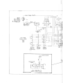
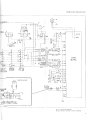
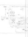
16. COVER AND SPEAKER ASSEMBLY(Figure 15).
No special instructions are necessary for repairing the cover and speaker assembly. Refer to the
accompanyingschematic (Figure 16) for proper leadwire connections.
1?. TESTING AND REPAIRINC THE AMPLIFIER
ASSEMBLY (Figure 19). Amplifier circuit board
repairs are not recommended except as artemergency
measure and then only if qualified electronics personnel and test equipment are available. If a faulty
condition is ttaced to the amplifier, replace the
complete assembly' Using standard electrooic shop
test equipment and techniques, check the amplifier
assembly and its components for continuity and for
shorts and open circuits. Refer to the appropriate
wiring diagram for voltages and ratings of components and for test points. Defective solder-secured
parts can be replaced by cutting the leads as close
as possible to the body of the part or by unsolder-
ing the leads from their terminal points. !\hen unsold.riog, it is advisable to use a heat sink to avoid
the direct application of heat to adjacent components'
special
parts,
note the following
When replacing
precautions '
are furnished
a" Eaeh of the three transistors
with a special lock washer and a mica washer.
The lock washer is to be installed beneath the head
of the screw with its teeth against the flat washer.
Apply thermal compound (Bell & Howell Spec. 28-7001) to both sides of the mica washer and install
and the metal
this washer between the transistor
heat sink bracket. The metal eollector plate of the
must be toward the heat sink.
transistor
circuit must be.installed with
b. The intefrated
mark or notch toward the edge of the
its polarity
board indicated by the dashed arrow drawn on the
in Figure 19. This arrow is not
top of the circuit
imprinted on the integrated circuit.
S E R VI C E I N S TR U C TI O N S
Renuorrirltl7?quzd*ze
18. GENERAL REA.SSEMBLYINSTRUCTIOIIS.
a. Before reassembling parts, be sure to clean
them thoroughly. Metal parts can be immersed in
a pan of non-flammable solvent or wiped with a
cloth dampened with solvent: then blown dry with
a low pressure jet of compressed air or dried with
a lint-free cloth. Do not clean plastic or electrical
components with solvent. Simply wipe plastic arrd
electrical components with a clean, dry cloth. Cleaa
optical parts with a good quaiity lens cleaner and
lens tissue or a lint-free cloth.
b" When reassembly procedures include staking
or riveting operations, it is wise to perform these
operations before assembling other parts. Be sure
to support the majol casting or plate soiidly during
staking operations to avcid disrorting the casting
or plate.
c. '*tren installing electrical components. refer
to tbe appropriate wiring diagram at the rear of
the Parts Catalog for the proper connection of
leadwires. When resoldering components to the amplifier assembly (Figure 19), use a heat sink to
avoid the direct application of heat to adjacent
components on the board. Re.fer to patagraph 1?
for special instructions regarding circuit board component replacement.
d. Most of the nameplates and the instruction
plates are provided with an adhesive backing. Mai<e
certain tttat the area to which such parts are to
be secured is thoroughly clean by wiping with a
cloth dampened witlt solvent. - Remove the protective paper backing and brush the adhesive with a
mixuure of three parts Tlrlouol to one part of trichloroethylene. When the adhesive is taclcy, press
the namepiate carefu.lly but firmly in place. Wipe
away Emy occ'ess adhesive with a clotfi dampened
with solvent.
e. Lubrication instructions are provided in tbe
section of this senrice manual. Do
Introduction
not over-Iubricate. Apply grease and oil sparingiy
a-s indieated, and wipe away Erny excess lubricant
with a lint-free cloth. Gears should be lubricated
by specking the gear teeth and then nrnning the
projector for a few moments to distribute the grease.
Where oil is indicated, a drop or two will usually
suffice.
1n
].9" REASSEMBLING THE APERTURE PLATE (Figure 14).
a. Assemble the film guide (9) to the aperhrre
plate (10) with the screw (8). The right end of the
film guide should be square with the edge of the
aperhre plate.
b. .{ssemble the side tension spring (7) and the
film tension rail (6) to the aperture plate. the
ends of the spring should engage the notches in
the film tension rail and the center of the spring
should bear against the staked pin in the aperture plate. Assemble the spacer bushings (5) and
spriDg retaining cover (4) to tlte aperture plate
and install the two screws (3).
c. .{ttach ttre film guide rail (2) to the aperhrre plate wittr the two screws (1), tightening the
screws securely. Refer to paragraph 20, step d,
for installation instrucflons.
20. REA,SSEMBLINGTHE MECHANISM (Figure 13).
Rerssemble Figu.re 13 parts a.s outlined in tbe
following paragraphs.
NOTE: When reassembling 1592 model projectors
use only steps a through g following. When reassembling 1585 and 1590 model projectors, refer
to steps h and j only.
a. Assemble the strike (7K) to the ciutch slide
bar assembly (7G) with the screw (7H) and washer
(7J). Insert the shaft (?C) part way through tbe
right-hand arm of the mounttng bracket assembly (7L) arrd install the bumper (7D) on ttre end
of the shaft. Hold the slide bar assembly (7G)
in position between the arms of the bracket assembly and continue to insert t}le shaft, ass€mbling ttte flat washer (7E) and the spring (7F) on
the shaft before it is inserted through the lefthand arms. Install the three retaining rings (7B),
with the center ring to tlte right of the spring
and washer. The setscrew (7A) must be adjusted
at final assembly to limit slide bar travel. Assemble the complete clutch bracket assembly (7)
to the mechanism housing with the two screws (4)
and (5) and lock washers (6), and press down filrnly
on the bracket while tightening the screws. Assemble the adjustment bracket (3) to the end of
(R)
ETORS
F I L M OO
SU N DP-R O J C
M o D E L1S5 8 5 , 1 5 9 0 ,1 5 9 2
the longer screw (5) and install the washer (2)
and the round nut (1), tightening the nut finger
tight.
ism housing. Hold the cam firmly against the feeler
gage while tightening the setscrew (11) against the
flat of the camshaft. Remove the feeler gage.
b. Lightly gr€ase both bearing openings in the
cast arms of the mechanism housing. Press the
ball bearing (12) into its bearing opening until fully
seated. Asiemble the large bearing (29) to the
camshaft (30) until the bearing is seated against
the shoulder of the shaft. hstall the retaining ring
(28) to the camshaft with the bowed sudace of the
ring facing away from the bdl bearing.
NOTE:
Steps h through j, following
t}re 1585 and 1590 model projectors.
c. Assemble the three rubber bushings (25) into
the corresponding openings in the face of the worm
gear assembly Qal- Assemble the bearing assembly
iZg) to the wortn gear so that the fonned ears of the
bearing are aligned with corresponding notches in
the worm gear. Insert the bent ears of the clutch
yoke (21)
through the slots in the bearing assembly,
'assembling
the spring (221 oset the protrudwhile
ing finger of the clutch yoke and into the hole in the
tearlng assembly. Hold these parts together while
assembling the two shoulder pins (20) to the bearing assembly, pressing them in until ttrey engage
tha bent ears of the clutch yoke. Assemble the
trigger (19) to the sleeve bearing (18) and press
tle bearing through the bearing assembly (23) and
into the worm gear.
d. Insert the end of the camshaft (30)' with bail
bearing (29) aesembled, through ihe bearing hole
in the right-hand cast arm of the mechanism housing, To tbe shaft, assemble the loop restorer cam
(27;, shim washer (26) ard the assembled worm gear
group. Assemble the torsion spring (14) over the
[uO of the driven clutch (15), spreading the legs of
the spring so t$at they straddle the bent ear at the
top of tbe clutch. lnsert the hub of the driver clutch
(13) through the hub of the driven clutch, spreading
the legs of the torsion spring still further until one
of ttre lugs of the driver clutch is also straddled by
tle spring legs. lnstall the washer (17) and the assembled clutches on the camshaft. When installed'
the bent ear of tie driven clutch (15) must be parallel wittr the camshaft flat for the loop restorer
cam (27).
e. Slide the camshaft all the way in place, inserting the end of the camshaft into bearing (12)
while seating the large bearing (29) in the bearing
hole of the cast arm. Assemble the two retaining
rings (16) to the camshaft, one between washer (26)
and loop restorer cam (27); the other between washer
(1?) and clutch (15). Clutch and loop restor€r adjustments will be made after reassembly has been
completed.
f. Fasten the bearing loading spring (10) to the
cast arm of the mechanism housing with two screws
(9). Assemble the large retaining ring (8) into the
ring groove of the housing arm, with the bowed face
of the ring against the bearing (29).
g. lnsefi a 0.190-inch feeler gage between tlte
loop restorer caln and the cast arm of the mechan-
apply only to
h. Lightly gr€ase both bearing openings in the
cast arms of the mechanism housing. Press the
ball bearing (12) into its bearing opening untii fully
seated. Assemble the large bearing (29) to the camshaft (30) until the bearing is seated against the
shoulder of the shaft. Install the retaining ring (28)
to the camshaft with the bowed sur{ace of the ring
facing away from the ball bearing.
i. Insert the long end of the camshaft through
the bearing hole in the long cast aran of the mechanism houslng. As the shaft end protmdes through
the cast arm, assemble the loop restorer cam (27),
shim washer (26) and worrn gear (24, to the shaft.
Continue sliding tlre shaft to the left, inserting the
end of the shaft into the left-hand bearing (12) while
seating the large bearing (29) in the bearing opening
of t}le right-hand cast aran. Make certain that both
bearings are fully seated; t}en install the bearing
loading spring (10) to the left-hand cast arrn rvitb
the two scr€ws (9). Assemble the large retaining
ring (8) lnto the inner ring groove in the righthand bearing opening, The bowed surface of the ring
must face the large bearing (29).
j. tnsert a 0.190 inch feeler gage between the
cam and the cast arm of the meloop restor€r
chanism housing. Hold the cam firrnly against the
feeler gage while tighteni.ng its setscrew (11) against
the flat of the camshaft. Remove the feelel gage(24A) enough to
fighten
the worm gear setscrew
hold until final adjustment can be made.
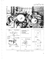
21. RE.dSSEMBLING THE MECIIANISM (Figure 12)"
Reassemble Figure 12'parts as outlined in the following paragraphs.
a. Assemble the shuttle retractor pin (29) and inout spring (28) and insert the rounded end of the pin
into the hole in the long cast arm, just to the right of
the camsha.ft. Secure the loop end of the spring to the
casting \rith the screw (27).
b. Screw the framer knob and shaft (26) down into
the mechanism housing. Orient the stop pin (25) so
that the flat side of the pin is parallel with and
facing the framer shaft, and press the pin in placeScrew the bearing support (24) ail the way up into
the staked nut of the shuttle arm plate assembly
end of the shuttle arm
(23). Engage the fork-like
plate framing arrn with the cut-out at the lower end
shaft, and fasten the plate to the
of the framer
cast arm of the mechanism housing with the two
screws (22).
c. Loosely assemble the in-out cam (20) to the
cam bracket assembly (21) so that the nylon face of
(21A) rides against the polished
the cam follower
surface of the cam (indicated by the dash arrow in
11
S E R V I C EI N S T R U C T I O N S
Figure 12). Irxsta[ tlris assembled group over the
end of the camshaft and secure the cam bracket assembly to the cast arm of the mechanism housing
with the two screws (19).
d. At this point, refer to Figure 11 and install
the assembled aperfure plate (65) with screws (64).
Then return to Figure 12 and continue with reassembly as follows.
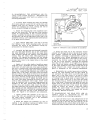
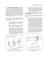
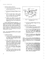
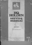
e. Make certain tlrat the shuttle link bearings
(L?A) are firmly pressed into the notches at the
front end of each shuttle arm (17) and that the
cam followers (178) are assembled into the center
notched section of each arm (see Figure B). Insert
the lubricated cam wiper wick (15) into the eoils
of the extension spring (13). Assemble tbe lubricated felt wiper (14) and the extension spring (13)
to the shuttle arrns as shown in Figu.re B. Assemble
the ball and stud assemblies (12) to the ends
of the artns with the hex nuts (11), tightening the
nuts only fingertight. Carefirlly insert the front
ends of the shuttle arms between the guides of
the in-out bracket assembly (2I1. Assemble the
sbuttle (16) to the front ends of tire shuttle arm
so that the shuttle teeth exteud through ttre shuttle
slot in the aperture plate and face in toward the
mechanism housing. Rotate the in-out cafir (20)
until the tongue protruding from the unpolished
face of the cam r€sts down in the notch in the
shoulder of the camshaft. Assemble the puli-clown
cam (18) to the eamshaft, spreading tlre shuttle
arms lightly until the cam ls fully in place. The
notch in the inner face of ttre pull-down cam must
ECCET,,lTR
Ic
F R A MI N G A R I ' 4
I
S H U T T L EA R M
P L A T EA S S ' Y
C A MF O L L O W E R
engage e mating protrusion on the faee of the inout cam. Back out the bearing support (24) until
its socket-like nylon pad engages the ball of tlle
upper stud assembly (12). The ball of the lower
stud assembly should rest in the socket of the nylon
pad mounted on the shuttle arm plate assembly (23).
It may be necessary to loosen the hex nuts (11) and
shift the ball and stud assemblies (12) until proper
aligament is obtained.
f. lnstall the fiber washer (10) on the camshaft
and up against the pull-down cam (18) so that the
slot in the washer is aligned with tfie slot in the
ca:rr. Assemble the shuttel (9) to the camshaft and
install the counterbalance weight (8) so that its pin
engages the slots in the shutter and the pull-down
cam. Install the shutter nut (7) with its shoulder in
the center hole of the counterweight. Grip the flats
at the end of the camshaft witb an open-end wrench
and tighten the nut (7) securely
g. 1592 Models Only. Assemble the grommets
(37) into tlle bracket (36). Assemble a retaining
ring (30) into tbe groove near€st the end of the
stop pawl shaft (31) and insert the opposite end
of the shaft through the shaft hole in the bearing
bracket (34) and both ears of the stop pawl (32),
Loosely attach the bearing bracket to the cast arzn
of the mechanism housing with two screws (33).
-A,ssemble bracket (36) to the opposite end of the
shaft and fasten the bracket to tbe mechanism houslng with screws (35). fighten screws (33) and (35)
securely. Assemble the second retaining ring (30)
into the groove of the shaft so that tlte right-hand
ear of the stop pawl is held against the bearing
bracket (34).
NOTE: Only the 1592 model projectors are equipped
witf,r the fire shutter assembly (4). On 1585 and
1590 model projectors. a stlpport bracket is installed
in place of the fire shutter.
h. Insert the rounded end of the heat baffle (6)
up under the shutter and secure tle balfle with the
two screws (5). Fasten the bracket or fire shutter
assembly (4) to the mechqnism housing with four
scr€ws (3) aJxdwashers (3A). Install the putley (2)
on the end of the camshaft, and tighten the pulley
setscr€ws (1) down on the flats of the shaft.
22. REASSEMBTING TtlE MECHANISM (Figure U).
Reassemble Figur€ 11 parts as outlined ia thefollowing paragraphs.
BALLAND
S T U DA S S Y
F E L T WI P E R
Figure B. Shuttle and Shuttle Arms Assembled
L2
a. Attach the self centering assembly (63) to tlre
mechanism housing with the two screws (60), lock
washers (61) and {lat washers (62). Aesemble the
lever and sbaft assembiy (58) to the mechardsm
housing and install the washer (57) and artn assembly
(56) on the end of the shaft. The fork-like finger of
the arm assembly must engage the pin of tbe self
centering assembly between the two large washers.
Insert a 0.0015-inch feeler gage betweentbe washer
(57) and the machined boss of tlp housing. Grip the
shaft (58) and arm (56) to hold the feeler gage while
fR)
FI LMOSO
NU
D " PR O J E C T O R S
M o D E L1S5 8 5 , 1 5 9 0 , 1 5 9 2
tightening the hex head screw (55); then remove the
feeler gage. Assemble the retaining ring (59) to the
shaft assembly (58).
NOTE: The shaft assembly (58), when installed,
must be positioned approximately as shown in Figure 11, with the notched area in its upper edge positioned beneath the lower sprocket shaft bearing
of the mechanism housing.
b. Assemble the cam follower parts (54A) thlough
(54F) as shown in Figure 11. Attach this assembled
group to the arm assembly (56) with the screw (52)
and washer (53). fighten the screw justenough to hold
the follower group. Ilook one end of the spring (51)
around the end of the lever shaft (58) and secure the
other end to the mechanism housing with the screw
(49) and washer (50).
c. Assemble the film escape mechanism components (46.4,)through (46G) in the following manner. Assemble the hub assembly (46F) to the locking pawl
(468) with the screw (46D). Insert the shaft (468)
through one ear of the upper loopformer assembly
(46G) and install the spring (46C) and the assembled
hub and pawl on the shaft. Then engage the end of the
shaft with the second ear of the loopformer. Assemble the retaining rings (46A) to the shaft, with the
center ring between the spring (46C) and hub assembly (46F). Hook one end of the spring over the
outer ear of the loopforrner and hook the other end
behind the upper finger of the hub assembly (46F)'
The spring should tend to rotate the hub and locking pawl in a clockwise dir€ction.
d. lnstall the torsion spring {44), short leg first,
on the shaft of the shaft aod link assembly (43) and
insert the shaft through tlie bearing in the mechanism housing. Hook the long leg of the spring beneath
the tapped mounting boss in the upper left-hand
corlrer of the mecharrism housing. Hook t}te short,
bent end of the spring behind the left edge of the
link" Assemble the washer (45) and the film escape
mechanism parts (step c, above) to the protruding
end of the shaft (43) and temporarily tighten the
setscr€ws (42).
e. .A,ttachthe upper sprocket grard mounting plate
(41) to the mechanism housing witb two screws (40),
tbe upper screw being inserted ttrrough the halJmoon slot in the upper loopformer (46G).
f. Attach the lens carrier catch (38) to the mechanism housing with the screw (3?). T\rrn the hex
head lens stop screw (36) into the tapped hole in
the bousing until only one thread is visible. It may
be necessary to adjust the catch and stop screw at
final assembly to insure proper operation of the
lens carrier.
g. Assemble the shuttle retractor (34) to the
link and stud assembly (35) witb t}te screw (32),
lock washer (33) and flat washer (33A). Assemble
the upper loopformer assembly (31) to the upper
end of the connecting link (35) and install the retaining ring (30). Slip the pin end of the threading
' lever (28) up behind the link (43), engaging the
pin with the rectangular
slot in the link. lnsert
the shaft of the loopformer
assembly through the
mounting plate (41) and mechanism housing, and
into the hub of the threading lever (28). Tighten
the hex head locking screw (27) securely. Attach
(26) to the upper loopform
the leaf spring
with
two screws (25).
h. Assemble the small hole in the film guide (24)
over the pin in the lower sprocket guard mounting
piate (21) and hold the film guide in place while inserting the shaJt of the toggle lever assembly (23)
forked
end of the
through the guard plate. The
toggle lever must straddle the film guide mounting pin. Secure the toggle lever to the mounting
plate with the retaining
ring (22). Engage the remaining forked end of the toggle lever with the pin
at the lower end of the eonnecting link (35) and secure the lower mounting plate (21) to the mechanism
housing with the two scre',vs (20). The fifm guide (24)
must be lifted slightly during this operation so that
its large pivot hole slides over the sprocket shaft
bearing in the housing.
i. Assemble one large washer (18) and the lower
film guide (19) over the lower sprocket bearing, at
the same lime inserting the pin at the lower end of
the connecting link (35) through the hole in the arrn
gurde (19). Install tbe second large
of the film
washer (18) and secure these parts with the retaining ring {17).
j. Fasten the back-up bracket (16) to the mounting plate (21) with the screw (15). -A,ssemblethe loopform (13) and tlte torsion spring (14) onto the lower
pin of the connecting link (35) and install the r€taining ring (12). The legs of the springmust bear against
the underside of the loopform in such a manner that
they will force the loopform to pivot clockwise around
the connecting iink pin.
.
k. Assemble the film guide (11E) to the autotbread lever (11F) with the screw (11D), tightening
the screw finger-tight.
Assemble the roller (11C)
and film guide (11B) to the shaft of the autothread
Iever and Eecure with the screw (11A).
l. Assemble the autothread lever (11) and eccentric (9) to the mounting plate (21) with the threaded
stud (8). The loopform (13) must be pivoted counand held in that position while installterclockwise
ing these parts. Again hold the loopform (13) in tbe
counterelockwise
rotation while securing the idler
roller (7) to the stud (8) with the screw (6). Reiease
the loopform (13). .{ssemble the torsion spring (10),
short leg first, to the eccentric (9). Hook the short
leg of the spring into the hole in the mechanism
housing above and to ttre left of the eccentric (9).
Ilook the long leg of the spring in the V-like notch
along the left edge of the lever (11).
m. Assemble the torsion spring (5) and threading
arm (4) to the stud in the lower right-hard corner of
the mounting plate (21). Engage the legs of the spring
l3
S E R V I C EI N S T R U C T I O N S
so that they tend to pivot the threading arm clockwise. lnstall the retaining ring (3) to secule the arm
to the stud,
n. Install the rollers (21 on their respective
studs and secule them with the serews (1).
23. REASSEMBLING THE LENS CARRIER (Figure
10). Reassemble the lens carrier assembly as outJined in t}te following paragraphs.
a. Lightly g?ease the gear teeth of the pinion a.ssembly (5M), the pinion slots of the carrier (5N)
and the notches of the pinion spring (5L).
b. Assemble the spring (5L) into the two grooves
of the pinion assembly (5M) and assemble the pinion
into the grooves of the carrier (5N). Fasten the
spring securely with the two scr€ws (5K). Check to
make certain that the loob rotates smoothly.
c. Place the pressure plate (5B) on the work surface, polished surface down and the forked end of the
plate to the left. Assemble the pressure plate lever
(5F) to the pressure plate with the small extrusion
of the lever fitted into the corresponding hole in the
pressure plate. Assemble the flat washers (5D)
into ttte springs (58) and assemble tbese parts and
tlte adjustment plate (5H) to the pressure plate, with
the shorter bushing located at tbe lever (5F). InstaU
and tighten the two screws (5A).
d. Slip tlte adjustment plate, with pressure plate
assembled, into place within tbe lens carrier and
loosely install the two screws (5G). tnsert the lens
plug (Figure A) into the lens bore of tlre carrier with
the rectangular boss of t"heplug fitted into tbe opening in the pressure plate. Tighten screws (5G) secnrely and withdraw the lens plug.
e. Clean the nameplate area of tlre lens carrier
with a cloth dampened with solvent. Remove thebacking from the nameplate (5J) and activate the adhesive
as instructed in paragraph 18, step c. Assemble the
nameplate to the lens carrier and wipe away exeess
adhesive with a soft cloth dampened with solvent.
24. REASSEMBLING THE MECHANISM (Figure 10).
Reassemble Figu.re L0 parts as outlined in thefollowing paragraphs.
a. Rotate and hold the lower loopform (13, Figrrre
L1) fully counterclockwise and assemble the filter
exit guide (32, Figur€ 10) to the mechanism housing
with the screw (31).
b. Assemble the sprocket guards (2?) and (28),
rollers (29) and torsion springs (30) to the tapped
mounting posts of the gu.ard mounting plates" The
rollers must be assembled as shown in the inset
of Figure 10. The inner bent end of each spring is
inserted into small spring holes in the morurting
plates adjacent to the tapped posts. The outer bent
end of each spring hooks over the outer edge of each
sprocket guard (27) and (28). The springs should
tend to rotate the free (unmounted) endof the sprocket
L4
guard toward the sprocket bearings in the mechanism housing. Secure the sproeket gu.ards to tlreir
mounting post with the screws (25) and the shim
washers (26).
c, Assemble the spring (241 to tbe shaft of the
rew'ind button (23) and insert th'e shaft down into
the opening in the top of the mechanism housingDepress the button and assemble ttre retaining ring
(22) into the groove at the lower end of the shaft.
d. Assemble the sprocket flange (20) and thrust
washer (21) onto tbe shaft of the lower sprocket assembly (J.9). Spread tlre two lower sprocket gu.ards
and insert the sprocket shaft through the lower bearings in the mechanism housing until the sprocket is
fully seated. Release the sprocket gr.r.ards.Assernble
a flat washer (14A), a spring tension washer (14)
and the lower sprocket gear (13) to tbe sprocket
shaft, meshing the sprocket gear teeth with the
worm gear. Align either setscrew (11) w'ith the
flat on the sprocket shaft and tighten both setscrews
securely. The sprocket and gear must iuln freely
but with only s minimum of end play.
e. Assemble the thmst washer (18) to the shaft of
tie upper sprocket assembly (17). Lift the free end
of the upper sprocket grard (27) and insert the
sprocket shaft through the upper bearings in t}re
rn€chanism housing until the sprocket is fnlly seated.
Release the sprocket guard.
guard parts (16A)
f, Assemble the sprocket
through (16D). Slip the assembled sproeket grard (16)
up into position beneath ttre upper spr€cket and secure the guard with two screws inserted from the
rear of the mechanism housing. Aseemble a flat
washer (14A), tension washer (14) and the upper
sprocket gear (12) to the sprocket shaft. Align
either setscrew (11) with the flat on the sprocket
shaft and carefully mesh the' sprocket gear with
tbe worm gear. Tighten both setscrews (U) eecurely. The sprocket and gear must turn freely,
but with a ninimum of end play.
g. Fasten the hood (10) to tbe mechanism housing
with the two screws (9). Press down and hold the upper loopfor:ner (31, Figrrre 11) while assembling the
actuating lever (7, Figure 10) to the lever shaft.
lnstall the rctaining ring (6).
h. Hold tJle assembled lens carrier {5) between
the hinge bosses of the mechanism housing. Insert
tlle flat washer (4) on top of the lower hinge boss
and the spring tension washer (3) beneatb the upper
hinge boss. Press the hinge pins (1) and (2) into
place to hold the lens. carrier. Adjust the lens
earrier catch (38, Figure 11) so that it holds the
lens carlier
firmly
against the stop screw (36,
Figure 11) in the closed position; yet pennits the
carrier to be opened easily.
i. All critical adjustments are to be made during
the final assembly of the projector and ar€ covered
in the Adjustments section of this senrice manual.
G')
ROJECTORS
F I L M OO
S UND-P
MoDELS
1585,1590, 1592
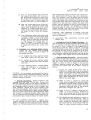
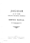
25. REASSEMBLING TI{E SOUNDHEAD .{ND EXCITER LAMP COVER (Figure 9). Reassemble the
soundhead and lamp cover parts as outlined in tlre
following paragraphs.
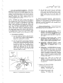
TENSION
A D J U S TRE
a. If exciter lamp mounting pin parts (31) through
(31C) were replaced, assemble the spring (31C) and
bushing (31B) into the opening in the casting and
insert the morurting pin (31A), forcing the end of
the pin carefully through the bushing.
LOWER
ARM
b. Fasten the terminal (30) to the sormdheadcasting with the screw (29). The free end of the terminal
should be approximately at the 5 o'clock position.
Loosely assemble the optical slit locking screw (10),
the setscrew (19) and the edge guide screw (24) to tlte
soundheadcasting. Leave approximately three threads
of the guide screw exposed.
c. Apply ahesive (B&H Spec. 176i.-34) to the end
four threads of the roller adjusting screw (14) and
assemble the screw to the soundhead, leaving approximatellr two threads exposed.
d. Assemble the light pipe and photocell assembly
(23) ard light pipe retainer (221 to the sound drum
and shaft assembly (21) and insert the sound drlm
shaft carefully through the opening in the soundhead
casting. Hold the sound drum while tightening the
setscrew (19) against the retainer (22) just enough
to hold all parts in place. Install the two scr€ws (20),
tundng them down in the tapped holes in the sound
drum housing.
e. Lightly oil ttte roller shafts of stabilizer arms
(15H) and (15J). Assemble the lower stabilizer arm
(15H) over the short shaft end of the upper stabilizer
arm (15J). Assemble the torsionspring(15G), straight
leg first, over the tapped hub of the lower stabilizer
arm (15H). Assemble the stabilizer artn (15F) to the
tapped hubs of the upper and lower arms and install
the two screws (15E). Ilook the bent end of the spring
(15G)through the small hole near'theendof stabilizer
arm (15F). Wind the straight leg of the spring one full
turrr clockwise and hook it behind the small post in
the lower arm (15H). Assemble the rollers (15C) and
(15D) to their respective roller studs. Roller (15D)
must be installed with its narrow flange nearest the
shoulder of the stud. Secure both rollers with the
screws (15A) and washerg (158). Insert ttte shaft of
the upper stabilizer arm carefully through the soundhead casting and the adjusting screw (14) and install
the retaining ring (13). Position the retaining ring for
0.0005 to 0.005 inch end play of the stabilize! arm
shaft. See Figure C for stabilizer and installation.
f. Lightly grease both surfaces of the lamp release ring (18) and assemble the release ring and
the lamp contact assembly (17) to the soundhead
casting with the two scr€ws (16).
g. lnsert the optical slit assembly (11) into its
opening in the soundhead casting and tighten screw
(10) just enoughto hold the slit in place.
UPPER
ARM
SPRING
SPRING
RETAI NER
Figrre C- Stabilizer Arms lnstalled on Suundhead
h. Insert the small end of the stabilizer tension
adjuster (27) through the hole in the top of the soundhead casting. Assemble the spring retainer (28) to
the adjuster, threading it approximately midway in
the threaded area. Before inserting pin end of adjuster into the small hole at the bottom of the casting,
assemble the friction washer (26), bowed face up,
to the end of the adjuster. Assemble the retaining
ring (25) into the groove at the upper end of the adjuster. Hook the tension spring (12) between the end
of the lower stabilizer arm (15H) and the hole in the
spring retainer (28). Instail tJre exciter lamp (8).
Refer to paragraph 40 for soutdhead adjustrnents.
i, Reassemble the exciter lamp cover as follows.
Remove the cloti backihg from the light shield (6)
and assemble the light shield to the left-hand inside
upper wall of the lamp cover (7) so that it is flush
with the outer edge of the cover. Flemove any excess
or overlap with a sharp lorife or raaor blade. Assemble the cover screw (2) to the cover and ins.tall
the retaining ring (1). Press the hole plug (5) into the
hole in the cover. Position the film guide (4) over the
tapped holes in the cover with the flange of the guide
wrapped around the front of the cover, and loosely
install the screws (3). lnsert a 0.020-inch spacer
between tlre guide flange and the cover, press the
flange against the spaeer, and tighten the screws
(3) securely. Remove the spaeer.
26. nEessrMBLINc
rHE REAR REEL ARM ASSEMBLY (Figure 8). Reassemble the rear reel
arm as outlined in the following paragraphs.
a. Apply one drop of oil to the unflanged end of the
bearing in tlre rear reel arm (32). Assemble one retaining ring (28) to the rear reel arm shaft (31) in the
groove nearest the two narrow flats on tbe shaft. Assemble the thrrrst washer (29) over the longend of the
S E R VI C E I N S TR U C TI O N S
shaft and down against the retaining ring. Insert
the shaft through the reei arm bearing. Assemble
the face geat (271to the reel arm shaft (31), gear
teeth facing up, and tighten setscrew (26) against
flat of shaft.
' b. Assemble the nylon bearings (25) into the cast
bearing arms of the rear reel arm, engaging the key
tabs of the bearings with the cross-slots of the bearing holes. Assemble the lower gear (22) to that end of
the gear shaft (24) where the flats are nearest tfie
end. The gear face with the squar€ recess must face
away from the cast bearing boss, Install the gear retaining ciip (21)- Insert the gear shaft through bottr
nylon bearings (25). Assemble the washer (23) and
gear retaining clip (21) to the end of the gear shaft.
Install the upper gear (20), square recess facing i.nward to engage clip (21), and assemble the grip ring
(19) to the end of the shaft. Insert a 0.010 inch feeler
gage between the upper gear (20) and washer (23) and
press the grip ring (19) in against the gear. Remove
feeler gage.
c. Assemble the rubber sleeve (12) to the hub of
the face gear (14). The sleeve must rest down against
the shoulder of the gear. lnsert the small diameter
end of gear shaft (16) up through the hole in ttte lower
end of the reel arm. Hold the shaft in place and assemble the washer (15), the face gear (14) and the
large washer (11) to the gear shaft. Secure these
parts with the retaining ring (10).
d. Install the setscrew (13) into the tapped hole
in the reel arrn casting near the lower end of gear
shaft (16). Do not tighten the setscrew. Move the
gear shaft (16) to engage the teeth of the face gear
(14) with the lower spur gear (22) and tighten the
setscrew (13). Rotate tlre face gear in both directions to check backlash. There should be approximately 0.005 to 0.018 inch backlash around the total
gear circumference. If necessary, loosen the setscrew (13) and remesh gear teeth until proper backlash is obtained; tiren tighten setscrew securely.
e. Apply a light film of grease to all gear teeth
and to the hub of the upper face gear (27). Assemble
the torsion spring (18) to the hub of face geat (27)
with the loop of the spring over the casung boss near
uppe! spur gear (20). Secure the spring loop to the
boss wittr the retaining ring (17). Rotate the upper
face gear in both dir€ctions to make certain ttrat
the r€taining ring does not r€strict movement of
the spring loop on the boss. Reposition r€taining
ring if necessary.
f. Apply one drop of oil to the mouth of the bearing in the take-up arm assembly. Assemble the
washer (8) to the shaft of the take-up spindie (7)
and insert the shaft through the take-up arm bearing.
Install and tighten the sctew (6). Assemble the
take-up arm to the mounting pin in the reel arm.
Assemble the take-up belt (4) arorurd the spindle
pulley and the rubber sleeve of the lower face gear.
See Figu.re D. lnsert the tension spring (5) into the
recess in the take-up arrn and compress the spring
16
T E N SI O N
SPRING
T AK E U P
bLL I
P U L L E YA N D
G E A RA S S ' Y
Figure D. Talce-Up Arm Assembled
wit}t a piece of shim stock while assembling the reel
arm cover (2) to tbe reel arm. Be sure to place a
shim washer (3) on each of the reel arm mounting
bosses before lowering the cover in place. Install and
tighten the two screws (1).
2?. REASSEMBLING THE FRONT REEL ARM ASSEMBLY (Figure 11. Reassemble the front reel
arm as outlined in the following paragraphs.
a. Assemble the washer (5C) and then the faee
gear (58) down against the shoulder of the feed
spindle (5D). Install but do not tighten the two
setscrews (5A).
b. Place the reel atm (22, on the bench with the
Iower (spindle) end of the arm at your left. Assemble
the nylon bearings (21) into the cast bearing bosses
of the reel arm, engaging the key tabs of the bearings wittr the cross slots in the bearing bosses. Insert t}re gear shaft (20) through the nylon bearings
from right to left, make sure that the end wit}t the
flats furthest from the tip of the sbaft is at the right
(upper end of tlle r.eel arm). Assemble the lower
spur gear (1.9) to ttre left end of the shaft. The gear
face with the square recess must face away from ttte
cast bearing boss. Install the gear tetaining clip (17)
to the flats of the gear shaft. Assemble tlre washer
(18) and the second gear retaining clip to uPper end
of the gear shaft (20). Assemble the upper spur gear
(16) to the shaft, with the square r€cess of the gear
engaging the retaining clip" lnstall the grip ring (15)
on the end of the shaft. Insert a 0.010-iueh feeler
gage between the upper spur gear (16) and washer
(18), and press the grip ring in against the gear. Remove ttre feeler gage.
c. Assemble the reiaining ring {11) into the ring
groove nearest ttre two fiats of reel atm shaft (14).
Assemble tlre washer (12) onto the shaft and down
F I LMOS
OUIIO@P
ROJ
ECTORS
M O D E L1S5 8 5 , 1 5 9 0 ,1 5 9 2
against the retaining ring' Place a drop of oil at the
unllanged end of the reel arrn upper bearing. lnsert
the long end of the shaft (14) through the upper bearing and install the spacer washer (13) and the second
retaining ring (11). Make certain that the setscrews
(8) and lee; are not protruding into the shaft hole of
the face gear (9) and that the sleeve (9A) is in place
on the hub of the gear. .{pply a light coat of grease
to the gear teeth. Assemble the torsion spring (10)
to the hub of the gear with the loop end of the spring
furthest from the gear teeth, Assemble the face
gear to the reel arrn shaft wtrile engaging the loop
end of tbe spring over the spring boss of the reel
arrn. Secure the loop with the retaining ring (7)
and tighten tbe gear setscrew (8) securely. The
retaining ring (7) must not be so tight as to restrict
movement of the spring loop when the face gear is
rotated.
d. Apply one drop of oil at the flanged end of
the reel arm lower bearing. Assemble the feed
spindle assembly (5) down through the reel arm
bearing. Iastall and tighten the screw (4) securely.
e. Rotate face gears (5B) and (9) in both directions to check backlash. There should be approximately 0.005-0.018 inch backlash around the total
circumference of each gear. By the trial and error
method, loosen the gear setscrews (5A) or {E) and
reposition the engagement of face gears with spur
gears until proper backlash is obtained. Then tighten
setscrews securely.
f. Place a shim washer (3) on each of the reel
arm mounting bosses arrd carefu-Ily assemble the
cover (2) to the reel arm. Install and tighten the
two scr€ws (1).
28. REASSEMBLINGTHE BASE COMPONENTS(Figure 6). Reassemble Figure 6 parts as outlined in
the following paragraphs.
a. Lightly grease the teetb of the worm gear (44),
tilt gearshaft (41) and ge€rr rack (39). Assemble
spring washer (421 to the tilt gearshaft (41), b-rwed
surface toward the worrn gear. hsert the shaft
througb the hole in the base and secure it with
the retaining ring (40). Fasten the tilt adapter (38)
loosely to the base with the screw (37). Assemble
the gear rack (39) and worrn gpar (44) into the
base, holding the worm gear between the two formed
ears of the base with all gear teeth (worm gear,
gearshaft and tilt rack) engaged. Secure the worm
gear wittr a new spring pin (43). Position the tilt adapter (38) so that the gear rack does not bind in
the rectangular eut-out and tighten the screw (37)
secur€ly.
b. Assemble the rubber feet (31) and flat washer
(32) to the base with the four screws (30). Assemble the tilt bar (28) to the lower end of the gear rack
(39) with the screw (26) and lock washer (27). The
short leg of the tilt bar must be toward the front
(operating side) of the base. New rubber feet (29)
ar€ cemented to tlre filt bar.
c. -A.ssemble the voiume and tone control assembly (25) into the base and secure with the four
screws (24). Check to make eertain that the conloobs are not binding in the cut-outs of the
trol
base before tightening the four screws.
Do not
install
the cover (23) until all wiring connections
and adjustments have been made.
d. Assemble the edge connector (18) to the amplifier
(20) and position these components within the
base. The two spacers (21) are positioned between
the amplifier
and base at the end furthest from the
tilt bar. Loosely assemble the two amplifier screws
(19); then install the two edge connector scr€ws
(17) and tighten all screws securely. Do not install
the cover (16) urtil all wiring connections and adjustments have been made.
e. T\rrn the base right side up and, if the mainplate (35) had been removed for any reason, assemble the mainplate
to the uprights of the base
with tbe four screws (34).
NOTE:
.{t this point, refer to Figure 5 and carefully assemble the complete mechanism
assembly
(29) to the mainplate with the four screws (27l,the
upper two screws also serring to attach the idler
gear adjustment bracket (28). Then refer to Figure 6
for balance of reassembly as follows,
f . Assemble a roller (10C) and the adapter (108)
to the shaft at the squared end of the film guide
bracket
(10D). .{ssemble the second roller
(10C)
'the
fo
shatt at the rotrnded end of the film guide
bracket and install botlr retaining rings (fOA). Engage the free end of the adapter (10B) with the
gu.ide rails of the film guide which is assembled
to the lower rear conrer of the mechanism
assembly (see Figure 11, item 11Il). Lower the rear
guide assembly (10) so that the
end of the film
ears of the adapter (108) are between t}le cast
ears of the base. Holq the guide roller (8), large
diameter
facing out, between the ears while installing the adapter shaft (7) through the cast ears
arld foller.
trstall
the screw (9) to secure the assembly.
g. Assemble the lever stop and pin (5) loosely
to the base with the screw (4). The lever stop must
be adjusted after the mechanism assembly has been
installed. Refer to step a, paragraph 29 following.
29. INSTALLING THE RUN-STILL LINKAGE (Figure 5). Reassemble Figure 5 parts as outlined in
the following paragraphs.
Lightly giease the elongated slot
a. All Models'
surface of the belt sbifter bracket
ana s1idiiE6E6t
assembly (25) and assemble the spacers (26) and
bracket assembly (25) to the tapped bosses of the
projector
main plate with the two shoulder studs
(24). Assemble one loop end of the torsion spring
(23) to the right-hand shoulder stud (24) and the
other loop end to the bent ear of the bracket assembly just above the shoulder stud. Install the
(22) to retain the spring loops.
rings
retaining
L7
S ER VI C E I N S TR U C 1I O N S
b. All
Models.
Assemble
the
lever
stop
and
pin assembly {5) to the base with the screw (4).
Before tightening the screw, insert a 0.060 inch
(1.52mm) shim between the stop pin and snubber
lever of the mechanism assembly. Rotate the stop
until the stop pin just touches the shim and hold
the stop securely while tightening the screw (4)
securely. Remove the shim.
NOtgr Steps c through g, following, apply only to
1592 model projectors.
c. Assemble one loop of the torsion spring (20)
over the shoulder stud of the pivoting link assembly
(18). Assemble the large washer (21) down against
the shoulder. Position the link assembly against the
projector mainplate, with the end of the stud engaged
in the rectangular opening just below the projection
lamp socket area, add the otherendonthe tapped boss
of the mainplate. Insert tJre spacer (19) between the
link assembly and the tapped boss and install the
pivot screw (15). Secure the shaJt of the link (18)
with the washer (17) and retaining ring (16).
d. Engage the remaining loop of the torsion spring
(20) with the pin at the lower end of the sliding link
assembly (13) while assembling the spacers (14) and
sliding link to the projector mainplate. Install and
tighten the two shoulder screws (12).
e. Assemble a retaining ring (9) into the ring
g3oove closest to the slotted end of the switch shaft
tube (11) and insefi the short end of the tube through
the mainplate from the front. Assemble the run-still
arrn assembly (10) over tbe protruding end of the
tube (11), engaging the key lugs of the arm in the
slot of the tube and the slot in the end of the arm
wittr the staked pin at the upper end of the sliding
Iink assembly (13). Install the second retaining
ring (9) into the ring groove at the end of the
tube (11).
f. lnsert the long straight end of the fire shutter
rod (8) down behind the pivoting link assembly (1.8)
and through the hole in the bent ear of the link. Engage the upper end of the rod with the hole in the
fire shutter filter arm. Assemble the spring (7) and
collar (6), small diameter up to the lower end of the
rod, and tighten the collar setscrew (5).
9. Assemble a collar (2), small diameter up, to
the still-mn rod (4). Insert the straight end of the
still-run
rod up through the hole in the tip of the
stop pawl of the mechanism assembly. Hook the bent
end of ttre rod through the hole in ttre long arn of the
pivoting link assembly (18). Assemble the spring (3)
and the second eollar (2), small diameter down, to
the upper end of the rod" Slide the lower collar up
against the underside of the stop pawl and compress
the spring slightly with the upper collar. Tighten
both collar setscrews (1) secureiy.
30. INSTALLING TTIE SOUNDHEAD, REEL ARMS
AND GEAR.S(Figure 4). lnstall Figure 4 parts as
outlined in the following paragraphs.
18
a. Carefuliy assemble the soundhead assembly
(40) to the projector mainplate. Be sure that all
leadwires are pulled through behind the mainplate
so as not to be pinched between the mainplate and
the soundhead. Hold the soundhead while installing
and tightening the three serews (36) andtheirwashers
(3?). Refer to the appropriate wirlng cuagram at the
rear of tJte Parts Catalog for proper wiring connections between soundhead and other projector parts'
b. Assemble the bowed washer (34) and the flywheel (35) to the sound drum shaft, with the bowed
face of the washer against the flywheel. Install the
flat washer (33) and retaining ring (32) on the end
of the sound drum shaft. Spin the flywheel to make
certain ttrat tJ:e shaft rotates smoothly.
c. Insert a spring (31) and a leel arm lock button
(30) into the opening to the right of the rear reel arm
mounting hole in mainplate. Ilold the button in with a
piece of shim stock while assembling tbe rear reel
arm (29) to the mainplate, Assemble the reel arm
disc (27) over the shoulder of the reel arm, with the
bent fingers of the disc pointing away from the mainplate. Align the screw holes in the disc with those in
the reel arm and install and tighten the screws (26).
Install the front reel arm assembly (28) in the sa.rIre
manner,
d. Assemble the sput gears (25C), hubs inward,
to the gear studs of the rewind lever assembly (25D).
Place a washer (258) on tie gear stud nearest tlre
end of tlle lever, and secure the gears with the retaining rings (25A). Hook the bent end of tlte long leg
of the spring (24) through the hole in the upper lip of
the rewind lever (25D) and assemble the spring loop
and the rewind lever to the gear stud of tlre mainplate (located near the upper left-hand corner of tlre
cut-out for the mechanism assembly). Wind the short
leg of the spring one full tural counterelockwise and
hook the bent end behind the edge of the sut-out.
Assemble the idler gear (23),,hub inward, and the
washer (221 to the protruding gear stud, mesbing
gear (23) \rith gears (25C)' install t}le rctaining
ring (21).
e. Assemble the gear retaining key (19) to the
slot of the front reel arm shaft. Assemble the rewind gear (18) to the shaft so that the square recess
in the inner face of the gear engages the retaining key. tightly grease tbe outer hub of the rewind
gear. Assembie the clutch gear (17) to the shaft
with the longer end of the clutch gear mating up
with the formed outline of the rewind gear. Assemble the gear and bearing assembly (16) to the
shaft and up against the clutch gear so that the
bearing spring is positioned between the two bosses
on the face of the clutch gear. Install the retaining ring (15) into the groove of the shaft to lock
the entire clutcb assembly in place.
f. Assemble the gear (11B), long hub out, to the
gear stud of the arm assembly (11C) and install the
retaining ring (11A). Assemble the !€w'ind clutch assembly (14) and flat washer (13) to theupper sprocket
shaft and assemble the gear r€taining key (1'2) to
6)
F I L M O S O U N DP-R O J E C TO R S
M O D E L S1 5 8 5 , 1 5 9 0 , 1 5 9 2
the flats of the shaft. Assemble the large hole in
the idler arrn over the inner shoulder of the spur
gear (9) and install these parts and washer (10) on
the upper sprocket shaJt. Slide the gear (9) inward
until the square recess in its face engages the key
(12). The staked pin of the idler arm must be incut-out in the rewind
serted into the triangular
Iever (25D). Install the spring tension washer (7)
bowed face out, and the grip ring (6).
g. Install the washers (5) and spur gears (4), hubs
in, on their respective gear studs, and secure them
rings (1). Assemble the washer
with the retaining
(3) and the spur gear (2) io the shaft and install
the retaining ring (1).
h. Speck all gear teeth sparingly with grease'
A.fter the projector is completely assembled, grease
briefly'
by running the projector
can be distributed
31. INSTALLING ELECTRICAL COMPONENTS (Figure 3). Install Figure 3 parts as outlined in the
following paragraphs. Refer to the appropriate wiring diagram at the rear of the Parts Catalog for
proper connection of leadwires between components.
Place the solenoid assema. 1592 Models Onlv.
bLy g7) on the work surface with the rod pointing
toward you and the tapped holes in the solenoid
Place
at the right).
bracket
facing up (leadwires
the mounting plate (4?B) over the tapped holes,
with the leg containing the single mounting hole
toward you and at the left. Install and tighten the
two screws (47A). Assemble the three rubber bushfirst,
into the mounting
ings (46), small diameter
holes of the mounting plate (478). Install a collar
(43), large diameter
first,
on the solenoid rod,
pressing
it up against the yoke while tightening
(42\. Assemble this solenoid group
its setscrew
to the support plate mounted on the long cast arm
of the mechanism assembly, while guiding the solenoid rod down through the hole in the tongue of the
stop pawl. Fasten the mounting plate (478) to the
support plate with the three screws
mechanism
(441, inserting
the spacer washers (45) between
the rubber bushings (46) and the mechanism support plate.
assemble the reamining
Temporarily
(43) on tbe lower end of the solenoid rod
collar
(beneath the stop pawl) and tighten its setscrew.
b. 1585 and 1590 Models Only. Attach the fuseholder (41) wiih the screw (40). Assemble the switeh
(38) to the projector
mainplate with the locking nut
(36) and lockwasher (3?).
c. 1592 Models Only.
Assemble the rotaryswitch
(35C) to the bracket assembly (35D) with the locking nut (35A) and lockwasher (35I}). Lift the assembled switch and bracket (35) up into position
against the mainplate while guiding the switch shaft
through the hrbe (item 11, Figure 5) already assembled to the mainplate.
Engage the free end of
the animation switch lever crank (item 37, Figure
10) into the hole at the top of the animation switch
bracket (item 34, Figure 3) and secure both switch
brackets
(34) and (35) to the mainplate with two
screws (33). Insert a 0.010 inch feeler gage between the animation switch lever (item 35' Figure 10) antl the mechanism housing and hold the
Lever against the shim rvhile pressing the crank
grip ring (item 35, Figure 10) in against the rnechalism housing' Rern,:ve the shim.
d. All Models.
Assemble the motor mounting
brackets (30) and motor bracket straps (28) with
stahilizer bracket (29) to the motor end caps. When
mounted to the projector base, the motor should
be positioned so that the nameplate can be easilv
read. Install the motor pulley (27) on the motor
shaft, small pulley diameter
toward the motor.
If the puliey was replaced, be sure to use the same
color of pulley asi the one which was removed.
Position the puiiey s{) that its inner lace is approximately l,/4-inch from the rubber mounting ring
of the motor and temporarily
tighten the setscrews
(26). Assemble the strain relief (241 to the jacket
of the line cord (25) and assemble the strain relief
into the center hole in the stabilizer bracket (29).
Loop the drive belt (23) around the motor pulley
and insert the end of the motor shaft through the
blower fan housing cover (22). Assemble the blower
fan (21) to the end of the motor shaft, with the fan
hub containing the setscrervs facing toward the motor. Position the fan on the shaft so that the end
of the shaft is approximately
1,/16-inch below the
face of the outer fan hub and tighten the two setscrews (20). .{ssemble the fan housing (19) to the
cover with the three screws (17). Manually rotate
the motor pulley to make certain that the fan is not
striking the cover or housing.
e. All Models.. Lift the assembled motor and
blorver group into position on the projector base,
threading
belt through the loop of t}te
the drive
belt shifter bracket assembl3r (item 25, Figure 5).
Guide the belt edgewise upward and around the
large mechanism pulley,. Align the motor and blower
mounting holes with those in the base, and install
(15) and
and tighten the eight mounting
screws
(16). Refer to the appropriate wiring diagram at
the end of the Pafis
Catalog section and make
the necessary wiring eonnections.
f. 1590 Models Onlv. Assemble the power transformer
assembly (14) to the projector base with
the four screws (13). Reter to the appropriate wiring diagram at the end of the Pzr'is Catalog section
for proper wiring connections.
E. 1585 and 1592 Models Onlv. Assemble tlre
brackets (10C) and (10D), mounting llanges facing
(10E) with the
inward, to the lamp transformer
screws (108) and hex nuts (10A). Make wiring connections to the tlansformer
according to the appropriate wiring diagram. Position the transformer
so
that the mounting holes in the bracket are aligned
with those in the base. lnstall the two front screws
(9); then tip the projector so that the two rear screws
(9A) can be inserted up through the base. Tighten
all screws. Assemble the brackets (7) and (8) to
with the screws
the top of the lamp transfolmer
(6) and hex nuts (5). Make wiring connections to
10
S ER VI C E I N S TR U C TI O N S
the power transforrner (4) aecording to the appropriate wiring diagram. Secure the power transformer to the upper fingers of the brackets (7) and
(8) with two screws (2) with lockwashers (3) and
hex nuts (1). Note that two sleeve spacers (3A) are
inserted between the bracket (8) and transformer
on 1592Hand 1592BHmodel projectors.
32. REASSEMBLING END CAPS AND LAMP COM.
PONENTS (Figure 2). Reassemble Figure 2 parts
es outlined irr the following paragraphs.
a. Pull the lamp leads through t}re access hole
in the mainplate and connect them to the terminals
of the lamphtrlder (15). Secure the lampholder and
the lamp shieid (14) to the mainplate wittt the two
screws (13), ald pull excess lamp ieads back behind the mainplate. Assemble the projectlon lamp
(12) into the lamp socket and swing the lamp retaining spring up into plaee.
b. Loosely assemble the still-mn lever (11A) to
the switch shaft with its setscrew. Assemble the
control knob (11) to tbe shafi, pressing in until
fully seated.
c. Assemble the a-xuiliary speaker jack (9) and
its insulating washer (10) to the rear end cap (7)
rvith the hex locking nut (8). Reassemble the rear
end cap components (7A) tbrough (7H), noting that
only the 1592 model projectors are equipped with
the Directamotion remote control receptacle (7F).
An adhesive-backed cover (7G) is installed over ttre
reeeptacle opening in 1585 and 1590 model projeetors. The starting capacitor (7C) is mounted
20
with its terminals up a-ndthe top end of the capacitor approximately 1/8-inch above the top edge
of the capacitor clamp (78). Secure the clamp to
the rear end cap with two serews (7A).
d. Assemble the speaker (68) over thefourmolded
pins of the front end cap (6C) and install the four
grip-type retaining rings (6A'). Speaker should be
installed with the terminals at the top.
e. Make certain tlrat all twelve speed nuts (5)
are in place on the formed mounting ears of the two
end caps. Position the front end cap assembly (6)
on the base with mounting holes aligned and, from
be:reath the base, install the two base-to-end cap
mounting screws (3) finger tight; then install two
screws (4) through the mainplate and into the speed
nuts on the front mounting ears of the end cap.
Tighten all four screws securely. Install the rear
end cap assembly (7) in the same mannerf. Assemble the tilt knob (2) ts the protruding
end of the tilt shaft and tighten tle setscrew (1)
securely" Rotate the tilt loob to check the tilting
mechanism.
g. Refer to the appropriate wiring diagram at
the md of the Parts Catalog section for proper
wiring connections.
33. REA,SSEMBLING LA.MPHOUSEAND COVEES
(Figure 1). No special instructions are necessary
for the reassembly of the lamphouse or cover components. These items need noJ be installed qtil
after all adjustments have been made (see the following section).
F I L M 0 S0 U N O @RpO Ig C t O R S
MoDELS
1585, 1590, 1592
4diualr*endt
34. GENERAL INSTRUCTIONS.
The alignment and adjustments covered in this
section are necessaly to the proper operation of
the projector. Even though the projector may not
have under-gone complete overhual and repair' it
is recommelrdedthat all the adjustments be checked
as a routine measure. Routine adjustments such
as those applicable to sliding fits, clearances and
end play have been covered in the reassembly procedures and are not repeated in this section except
where they directly affect other adjustments or
alignments.
and electronic test equipment (vacuum tube voltmeter, voltohmmeter, oscillator and tachometer or
Strobotac) are needed to check and adjust the sound
system of the projector. The test films are listed
in the Introduction section.
WANNINC
Many of the procedures listed in this section require operation with the rear'projector cover removed. To avoid shock hazards, disconnect the power and discharge
the motor starting capacitor, when not
required.
AII special tools and fixtures required to perform the adjustment procedures are listed and illustreted in Figure A. In addition, special test films
SOCKET
MOUNTINC
LENS PLUG (1}
-_.._-\
v
SPR.NG
PIN 6124
APER
PLUG
Figure E. Aligning the Optical System
E
S E R V I C EI N S T R U C T I O N S
35. OPTICAL ALIGNMENT.
It is important that these alignments be performed in the following listed sequence (steps a
through d). All special tools and fixtures required
for optical alignment are shown in Figu.re A. These
items are shown installed in the projector in tr'igure E. Be sure to tum the mechaaism manually
until the shutter blade is clear of the aperture
.opening, before inserting alignment tools.
a'@
(1) Remove the proiection lens from the lens
carrier, Open the lamphouse and remove
the projection lamp and the condensinglens
assembly.
(2) Swing the lens carrier fully open and disasse;nble the pressure plate from the lens
carrier.
(3) Loosen the two aperture plate mounting
scr€ws just enough to permit movement of
tbe aperture plate, and insert the aperture
plug (item 5, Figurc A) into the aperture
opening. Close the lens carrier.
(4) Insert the alignment rod (Sigure E) tlrrough
the lens plug until the rod end protrudes
enough to install the spring (P/I\ 6124).
Insert the lens plug into the lens barrel
until the tip of the alignment rod engages
the aperture plug previously installed. Tip
the projector carefully onto its back (lens
opening facing up). The alignment rod must
slide freely through ttte aperfire plug without binding. If necessary, shift tbe apertute
plate slightly until free rod movement is
obtained; then tighten aperhrre plate screws.
36. eo.lustlNc
rHE INTERMITTENT r\IECHANISM.
ce. Ada. Checking Shuttle Tooth Si
vance
le is
at the center of its stroke as shown in Figure F.
The clearance from the edge of the shuttle slot to
the inner end of tfie shuttle tooth (nearest the aperture opening) should be 0.007-inch minimum. From
the edge of the shuttle slot to the outer end of the
shuttle tooth, the distance should be 0.050-inch mo<imum. Check these clearances at both the upper
tooth and lower tooth. If the clearances vary at tlre
upper and lower teeth and inner clearance is less
than 0.007-inch at either end, the following possible causes sbould be checked and corrected.
(1) Aperhrrc plate out of alignment. See paragraph 35, step a, Aligning the Aperture
Plate.
(2) Shuttle stroke incorrect. See paragraph 36,
step d, Shuttle Stroke Adjustrnent.
(3) Link bearing missing from end of shuttle
arm. Partial disassembly reguired to r€move sb0ttle arm and teplace link bearing
(refer to Disassembly section).
(4) Ball andstud assemblylooseonshuttle aru.
Feposition ball and stud assembly (Figure
B) and tighten shrd nut securely.
0.050MAX.
0.007 MlN.
b. Atigning the Lamp Socket.
(1) Tip the projector back into its normal,
uprigbt position and reassemble the pressure plate to the lens carrier. Close the
lens carrier,
(2) Loosen the two lampholdermoutingscrews
just enough to permit movement of the
lampholder" Iasert lamp plug (1, Figur€ A)
into lamp socket and securethelampspring.
Slide aiignment rod completely into place
until tip of rod engagestheholeinlamp piug.
Shift socket as necessarT until rod slides
freely in the lamp plug hole. Thentightenthe
screws securelv and remove all tools.
22
x ; 0 . 3 0 2 5 t 0 . 0 0 0 5l N .
T R A V E LO F C E N T E RT O O T H
Figr:.re F. Aperture Plate and
Shuttle Tooth Clearance
6\
ROJE
CTORS
F I LMOS
OUND*P
M o D E L1
S5 8 5 , 1 5 9 0 , 1 5 9 2
Swing open the
Shuttle Tooth Height.
- b. +Checking
lens cariie r and advancEthe mechanism manually until the shuttle is at the center of its stroke as showlr
in Figure F. Hold the shuttle tooth height gage (Figure A) by its lanurled handle and place it against the
aperture plate between the rails. The center eats,
on either side of the gage handle, are the height
gages. Slowly slide the gage downward. T?te 'tco"
ear should pass over the shuttle tooth withoutcatching, Rotate the gage so that the rrNo-Go" ear is
over the shuttle slot and once more slide the gage
downward. 'Ihe "No-Goil ear must not pass over the
shuttle teeti. If the shuttle teeth are too high or two
low, adjust heightas follows.
NOTE:
If the mechanism assembly is installed on
to remove
it will be necessary
the mainframe,
the projection lamp and the lampthe lamphouse,
holder before proceeding.
(1) Turn the mechanism drive pulley by hand
until the access holes in the shutter and
the fire shutter braeket are aligned as
shown in Figu.re G.
(2) Insert a No. 4 Bristol Wrench into these
access openings and engage it in tbe socket
of the in-out can follower screw.
(3) If the shuttle teeth were too low (No-Go
ea! passes over sbuttle teeth), turn the
cam follower screw counterclockwise to
increase shuttle tooth height. E the sbuttle
teetb were too high (Go ear catches
against shuttle teeth), turtl the cam follower screw clockwise. It may be necessary to recheck shuttle tooth height with
tbe gage several times before the proper
height has been obtained.
(4) If one of the teeth cannot'be brought into
tolerance by the above method, it may be
necessary to loosen the screws which attach the in-out bracket (Figure G) and shift
the bracket siightly. Tighten the mounting
screws securely and check and adjust shuttle tooth height as outlined above.
Fit of Shuttle Arms to Pull-Down
ove rear cover
NOTE: If projector has just been lubricated, run for
two or three minutes before proceeding with this
adjustment.
(1) Open film gate and turn projector mechanism by hand until shuttle teeth are retracted and have moved downward to approximately the center of the stroke (center tooth
approrimately on horizontal center line of
aperture). Slip the guide bars of tool S-5524-Nl over castingto which shuttle mounting
plate is attached (Figure H). When tool (A)
is positioned so that stud (B) can bear on
shuttle arm (C).tighten thumbscrew (D)just
enough to hold tool in position. Engage hook
of tool S-552-4-Nz in the slot of stud (B) as
shown, and allow weight (E) to swing downward. Tilt projector, if required, so thatthe
weight does notrub on anystationary parts.
(2) Loosen upper bearing support assembly (F)
approximately one tum. Rotate projector
framer lcrob sothatpointer (G)moves above
witness mark (H). Then turn framer lorob in
the opposite direction until pointer (G)moves
back down in line with mark (H).
IN.OUT
S H U T T EA
RS S ' Y
B R A C K E T ( 3 - B L A D ES H O W N )
,CI
ii
I
IN-OUTCAM
FOLLOWER
F I R E S H U T T E RO R
S U P P O R TB R A C K E T
W EI G H T
S-552-4-N2
M U S TB E R E M O V E D
N O T E : D R I V EM O T O R
S O W E I G H TC A N S W I N GF R E E
N 0 T E : I N S E R T! , , l R E N CTHH R O U G H
A L I N E DH O L E SA T i l X r l
Figure G. Adjusting Shuttle Tooth Height
Figure H. Adjusting Fit of Shuttle Arms to
Pull-Down Cerm
OQ
S ER VI C E I N S T R U CITO N S
NOTE: If adjustment of framer knob does not permit movement of pointer (G) as specified, it may be
necessar]r to rotate the camshaft slightly to bring
cam into proper position.
(a) Bemove pressure plate assembly from
(3) Carefully tighten upper bearing supportassembly (F) while observing alignment of
pointer (G) with witness mark (H). The instant that pointer (G) starts to move upward,
stop turning support assembly (F), This is
the proper adjustment.
the lens carrier.
(b) Set the framer
knob at tlre mid-ooint of
its over-all travel.
(c) Suspend the target approximately 18
feet from the projector with center of
target on same horizontal line as optical a:<is of projeetor. If room arrartgement necessitates tiltingprojector,
target must also be tilted so that angle
between target and optical ards is 90 degrees. If this is not done, "Keystone't
error will be produced.
CAUTION: Do not tighten shuttle arrns more than is
specified in an attempt to remove cam noise. Excessive tightening of shuttle arms for the purpose of reducing other noises will reduee life of cam and cam
shoes.
d. Checking Shuttle Stroke. Normal shuttle stroke
(vertical travelofshuttle teeth) is 0.3025 inches (Figure F). The most convenient means of measuring the
stroke is to usethe projectoras anopticalcomparitor.
The step on the stroke gage (item 6, Figure A) is tJre
length of thenominal stroke. When itis inserted in the
aperture andprojected, it provides a reference dimension with which the actual stroke can be compared.
A sketch of a target is shown ia Figure J. The A to B
section is a 100 to 1 enlargement of the gage. The
C and D lines represent 100 to 1 enlargements of the
limits of tolerance.
(d)
Open the lens carrier and tum the projector mechanism by hand until shuttle
is at bottom of stroke and shutter just
clears aperture.
(e) Insert stroke gage (S-550-5-N2) in the
aperture plate and ligbtly press it down
against the top tooth of the claw. Close
the lens carrier.
(AS SEEN
TARGET
F R O MP R O J E C T O R )
l
I
I
S T R O K EG A G E
T O O T HA T B O T T O MO F S T R O K E
/
top
OF
N
O O TH
I U U I
STROKE
L IM ITS
UTTLE
eLl|rTTt tr
GAGE IMAGE
APERTURE
PL A T E
T O O T HA T T O P
OF STROKE
A D J U S TT H R O WS O T H A T
I M A G EO F G A G EE X A C T L Y
MATCHEG
S A G EL I M I T M A R K S
Figure J. Checking and Adjusting
Shuttle Stroke with Target
F I LMoS0U
NO@p
ROlrCrOnS
MoDELS
1595,1590,1592
(f) Turn on tlre projector lamp and focus
the image of the shuttle slot on the target. Moveprojectortoward or away from
tbe target until a sharpiy focused image
of the step at end of stroke gage just
reaches from line A to line B (FigureJ).
(g) Slide the stroke gage up out of field-ofview and tura mechanism pulley until
center tooth ofshuttle is at top of stroke
indicated by image of tooth neer line A.
Adjust framer, if required, until projected image of edge of tooth just touches
line A.
(h) Turn mechanism pulleyuntilcentertooth
of shuttle r€appears attop of target. Rock
mechanism pulley to find top of shuttle
€troke. Edge of tooth used as reference
in step (g) must fall between lines (C)
and (D) (Figure J). If image falls between (C) and (A), stroke is too short.
If image falls beyond (D), stroke is too
long.
(2) Procedure lor Adjusting Shuttle Stroke..
Loosen the two shuttle plate moulting
screws just euough to pemit movement of
the shurtle arm plate.
(a) To lengthen the stroke, shift the shuttle
arm plate toward the pull-down cam.
(b) To shorten the stroke, shift the shuttle
arm plate assembly away from t&e pulldown cam,
(c) After adjusting stroke, r€check shuttle
tooth side clearance as instructed in
paragraph 36, step a, and readjust if
necessalT.
CAUTION: Do not attempt to eliminate film slap by
setting stroke outside established tolerance. Thiswill
produce double image and/or jump with films having
diJferent shrink or st"etch.
e. FraminE Adjustrnent. Thread projector with
framing tegt film loop TFL-55-NX1. Project film
and turn framing knob from one limit to the other. If
at one limit a frarne line is not visible, Ioosen nut on
the framing eccentric located at top of shuttle arm
plate assembly (Figure B) and turn eccentric until
the frame liae appears. Ilold eccentric while tightening nut. Check adjustrnent by again turning framing
lgrob from limit tolimit while obserwingpicture. When
the eccentric is properly adJusted,either frame line
can be projected and movement of film shotrld be approximately equal at top and bottom of framer travel.
3?. IENS CARRTERADJUSTMENT. Angular relationship between the lens carrier and the aperture
plateis controlled by lens mount stop screw (item 36,
Figur€ 11). Thread projector with ro11title or target
film having sharp images incorners and project apicture approximately 30 inches high onto a matte surface. T?re projector must be square with the scleen.
Focus the picture and compare resolution of the two
sides of theimag€ when yiewed from a distance of approximately twice the width of the pictur€. If one side
appears to be soft, refoeus to sharpen that edge of the
picture and note whether the lens is moved toward or
away from the aperture. For example, if image at
right-hand edge of screen is soft until lens is moved
toward apefiure, then lens stop screw is set too far
forward and should be turned clockwise.
CAUTION: This adjustrnent is crifi,cal. Lens stop
sclew should be turned only a few degrees between
tests for sharpness,
33. ADJUSTING TIIE ANIM.C,TIONCLUTCH (1592
Modeis Only).
a, CheckinE Stop Pawl to TriEger Clearance, Rotate themechanism byband untilthe finger of the trigger is adjacent to the inner bent ear of the stop pawl
as shown in View A, Figure K. If the trig'ger fails to
clear tle stop pawl eat, adjust as follows. Looseu the
bearing bracket screws (item 33, Figure 12) and shift
the bearing bracket (item 34, Figure 12) up or down,
as necessary, to obtain approxlmately 0.010 to 0.015inch clearance between the stop pawl ear and the end
of the trigger; tben tighten the two screws securely.
b. Checking Shuttle HetracHon. Tirrnthemechanism pulley by hand wNle pressing dowu on the clutch
pawl at apoint wherethe clutch rod passes through it.
The ear of the clutch pawl should latch behind the
trigger as shown in View B, Figrrre K. Note also the
clearanee required between the finger on the clutch
yoke and tbe curved arm of the strike. .{djust as
follows:
(1) Loosen the clutch strike screw (View B,
Figure K) to perrnit the strike to be shifted"
Insert a 0.015-inch feeler gage betweenthe
clutch yoke finger and the strike arrn, and
press and hold the strike against the feeler
gage while retightening tlre strike screw.
Remove the feeler gage.
(2) -Refer to View C, Figure K. Loosen the
round Allennutslightly and shift the shuttle
adjustnent bracket slowly toward the sbuttle (to the right) until the shuttle teeth are
r€tracted below the level of the aperture
plate rails. Retighten the Allen nut.
(3) Refer
screw
0.094
clutch
to View D, Figu.re K. Adjust the setin or out to obtaln a clearance of
inch between the left-hand ear of the
slide bar andtheend of the setscrew.
(4) The shuttle interlock retainer is secured to
the right end of the worm gear. Note, in
View C, that the curred lip of this r€tainer
must overlap the downward bent finger of
the clutch slide bar. If necessary, bend this
finger to obtain positive overlap as shown.
26
S E R V I C EI N S T R U C T I O N S
I N G E RO F
SLIDE
CLUT CH
YO K E
SCLENOID
SOLENOI D
ROD
R
UPPE
COLLAR
t/6-
I
r
l
J
t
I
I
ll
vrEw
c
ilHT'bF^tRlY"'
R
LOWE
COLLAR
S TO P
PAWL
TR I GGER
TO
tN.
naL
SETSCREW
0 . 0 10 T 0
0.015-rN.
CLUTCH
S L ID E B A R
VIEW A
0 . 0 1 5l N .
CE
CLEARAN
S T RI K E
C L U T C HY O K E
FINGER
iIlrirll
SOLENOIO
C L U T C HS T RI K E
LN
B R A C K E T L O C KS C R E V i
LLUI
T O N G U EO F
O RI V E R C L U T C H
CLUTCH
YO K E
S O L E NIOD
PLUNGE
R
BEARI NG
T RI G G E R
COLLAR
(2)
CoLLAR
S P RI N G
R
UPPE
COLLA R
LLAR (l )
COLLAR
STOPPAWL r ? l
BENI EAR
E
S T O P L O WR
PAWL COLLAR
VIEW B
S TO P
PAW
L
S TI L L . R U N
R o D( 5 )
VIEW E
Figure K. Animation Clutch Adjustrnents
c. Adjusting Clutch Solenoid Linkage. Refer to
Figure K for the following adjustment procedure.
Rotate the mechanism by hand until the finger of the
stop pawl is centered at the tip of t}te trigger as
shown in Figrrre K, liew A, and place Still-Run
knob in rrFhrn.rr
(1) Refer to Figure K, View E- Loosen setscrews in collars (1) and (2) and press
lower collar (1) up against the underside
of the stop pawl until a clenrance of 0.010
2e
to 0.015-inch is obtained between stop pawl
finger and tip of trigger. fighten collar (1)
setscrew.
(2) With t}re tip of an appropriate spring gage,
press down on upper collar (2) until gage
indicates a spring pre-load of 5 ounces; then
tighten upper collar setscrew.
(3) Loosen setsct€ws in collars (3) and (4).Use
a suitable clamp to hold tlresolenoidplunger
l epc r o n s
F I L M o S O U NnOO@
M o D E LI S
5 9 5 , 1 5 g O ,1 5 9 2
'
up to its seat; then raise lower collar (3)
until it iust touches the stoP pawlandtighten
the collar setscrew. Position the upper colIar (4) so that tbere is 1/16 to 1/8 inch
clearance between collar and stop pawl and
tighten upper collar setscr€w.
d. Checking Still-Rru Linkage. Referto Figure K,
View E in this section for the following adjusknent
procedure.
(1) Rotate the projector Still-Rn hrob to the
ftrn position so that the still-ntn rod (5)
moves downward in the limit of its travel.
(2) Rotate the mechanism loob and check to
make certain that tlre ear of the stop pawl
clears tJre trigger as shown in View A,
Figure K(3) Operate the projector and switchfrom "llurl"
to trstillrr position. The stop pawl is engaged
with tbe trigger mechanically and is disengaged electricaily (by the solenoid). If the
preload tension of the spring (paragraph c,
step 2, pr€ceding) is set too low, the stop
pawl may not engage the trigger properly
and a chattering will result. If set too high,
the solenoid may not be able to overcome
spring tension to disengage the stop pawl
from tlre trigger. Readjust spring tension
until proper operation is obtained.
39. .{DJUSTING THE FIRE SHUTTER (1.592Models
orriy). When the projector has been completely
assembled, insta[ the projection lamp and lens and
run the projector 'rforilardrr with t}re lamp on. T\rrn
the Still-Rrn larob to tbe Still position and focus
the image of the aperhrre on the screen. Check for
full pattern of the fire shutter disc on the screen
(image must sbow per{orations of disc tbroughout).
Note that a bent ear onthe fire shutter bracket limits tbe travel of the fire shutter filter arm. If
unfiltered light appears at the top or bottom of
tbe aperture image, it will be necessary to bend
this stop ear so that the amount of filter arm
travel is incr.eased or deereased accordingiy.
40. ADJUSTING THE
CLUTCH.
Reel
c. Rewind Clutch Adjustment. The rewind clutch
a supply spindle
syste@ce
torque of.5-L/2 to 6 inch-ounces when the rewind button is pressed during operation. Install an empty reel
on the supply spindle and wrap several turrs of ateninch film strip around the reel hub. Hook a spring
scafe to the free end of the film strip. Tur:n on the
projector, rotate the "Motor-Lamp'
switch ;o ttffsversert aJrd press and release the rewind button at
tlre top of tbe mechanism housing. The spring scale
must register between 2.5 and 4.5 in.-lbs. When the
rewind clutch system begins to slip. Take-up torque
is adjusted by means of the take-up clutch assembly
(item 18, Figure 4). Grip the flats on the inner face
of the clutch v/ith a wrench while loosening or tightening the nut on the clutch hub. Fewind torque (also
2.5 to 4.5 in.-lbs.) is adjusted by means of the
rewind clutch assembly (item 14, Figur€ 4). This
clutch is installed with the adjusting nut facing inward toward tJ:e mainplate, and a special wrench
(item 5, Figure A) must be used for tbe adjustrnent.
41. ADJUSTING THE SOUNDHEAD.
a. SoundheadBemoval.
(1) Remove the prcjeetion lens from the lens
carrier and wrap it in tissue or a soft
cloth.
(2) Loosen the cover thumbscrew and remove
the exciter lamp cover from the soundhead.
(3) Remove the rear cover (Figure 1) from the
projector. Remove the assembled power
transformer and lamp transformer (Figure 3) from the projector base, being careful not to place undue strain on the transformer leads. Remove the flywheel (35,
Figure 4) from the sound drum shaft.
REEL Aru\4S AND REWIND
a. Front Reel Arm Adjustment (See Figure 7).
eajust
inch by positioning tetaining ring (11) againstan0.008
inch shim. The backlash for both face gears should
be between 0.005-inch (minimum) and 0.016-inch
(maximum). Adjustment is made by loosening tle
face gear setscrews (5A), (8) and (8A) and repositioning tlre face gears (5B) and (9) as necessary.
b. Rear
loosening its setscrew (26) and repositioning the
gear as necessary. The lower gear (14) is adjusted
by loosening the setscrew (13) in the tapped hole of
the artn and shifting the shaft (16) in and out as
necessarY.
Arm
ring (28)
inch by positioning
retaining
0.008 inch sbim. The backlash for bot}t
should be between 0.005-inch (minimum)
inch (maximum). The upper gear (27) is
against an
face gears
and 0.01.8adjusted by
1+i nefer to the wiring diagram at the rear
of the Parts Catalog section and disconnect or unsolder soundhead leadwires as
necessalY.
(5) Wittr a sharp pencil or scribing tool, scribe
a line on the projector main plate along the
front edge of the soundbead casting. This
will provide a referenee mark for locating
the soundheadduring installation.
(6) Remove the three scr€ws (36, Figure 4)
and flat washers (37) and carefully withdraw the soundheadassemby from the projector main plate, disengaging the Volume
control shaft from its opening in the soundhead housing.
27
S E R V I C EI N S T R U C T I O N S
b. Photocell Alignment (Figure 9).
(1) Loosen the setscrew (19) and the two housing screws (20). Remove the exciter lamp
(8) and the optical slit (11).
(2) lrsert the sound drum alignment tool into
the optical slit opening as shown in Figure L.
'
(3) Press the sound dnrm in rurtil its inner
face just makes contact witlt the first
step, or bearing surface, of t}te alignment
tool, and maintain this contact while tightening the two screws (20) securely.
(4) Withdraw the alignment tool and, while
looking into the optical slit morurting hole,
shift the photocell until its lorward tip is
flush with the inner face of tlle sound drum.
Maintain this position while tightening the
setscrew (19).
c. Boller Tension Adjustment (Figqlg_l).
The
. . roller arms ar€ Iinked by a torsion spring and,
ther"efore, will move as a pair. Ttre coruterbalance
spring must be adjusted to offset the weight of the
rollers and roiler arms. Place the soundbead on a
level surface and move the roller ams (as a set) to
various positions. If the roller arms fail to remain
in the set positions, engage tbe slotted head of the
iension adjuster vith a screwdriver aJrd turrr the
adjuster clockwise or counterclockwise r:ntil proper
counterbalanee is obtaiued.
NOTE: The following adjustments must be made
with the sowrdhead installed andtbe projector threaded
with special test film.
d. Soundheadlnstallation.
(1) Carefully assemble the soundheadassembly
to the projector mainplate, while inserting
the Volume control shaft through thesoundhead casting. Install and tighten the Volume
control mounting nut.
(2) instail the tlree sctews (36, Figure 4) with
their washers (37) fr-om the rear of the
mainplate and tighten the screws finger
tight. Shift the soundhead until the fo::vard
edge of the'sormdhead bousing is aligned
wit}t the scribe or pencil mark on the mainplaie and maintaln this position while tightening the three screws securely.
(3) Refer to the appropriate wiring diagram
at the rear of the Parts Catalog seetion
and reeonnect or resolder all soundhead
leadwires.
(4) Assemble the bowed washer (34, Figure
4), flywheel (35) and flat washer (33) to the
sound drum shaft and secure these parts
with the retaining ring (32).
28
L O C KI N G
SETSCREW
CLAMP
slLlcoN
PHOTOCELL
I N N E R E D G EO F
S O U N DD R U M
Figure L. Positioning the Sound Drum
and Silicon Cell
(5) Heinstall the assembled power transformer
and lamp transforner
(Figur€ 3) to the
projector base.
e. Optical Slit Adjustment (Figure 9).
(1) Insert the optical slit (11) into its opening
in the soundhead. The adjusting hole in
the barrel. of the slit must be at top center.
(2) Insefi a 0.050-inch feeler gage between tbe
tip of the optical slit and the sourd drum
and prress tbe optical slit in against the
feeler gage. Hold in this posltion vrhile
tightening tbe locking screw (10)justenough
to hold the slit in place.
(3) Thread the projector with audio franing
test filo TFR-D550-NJ(5 and connect a 16ohm, 16-watt load resisdor and output meter
to the speaker jack.
NOTE: A pair of hairpin tongs approximatety 6 inches long and fonned with the ends hrnred inward and
tapered to engage holes in end of slit barrel are very
usefirl in adjusting tle optical slit. They can be made
from 20 to 26 gage music wirc or L/LB inch diameter
drill rod.
(4) Set the volume control at approximately 12
o'clock position and start projector. Move
slit toward or away from film, as r€quired,
to obtain an output rcading. Rotate tbe slit
to obtain peak r"eading and simultaneously
move in or out until maximum outputis obtained. If film was thr€aded with emulsion
toward tbe optical slit, move slittowardfilm
until ou@ut drops L-l/z tp 2 DB. If emulsion is toward sound dnrm, move slit away
from film to obtain 1-L/2 to 2 DB drop in
ou@ut. Tighten slit elamping screw(10)eecur€ly to lock the adjustment,
€)
FILMOSOUP
NR
DO J E C T O R S
M 0 D E L1S5 8 5 . 1 5 9 O ,1 5 9 2
f. Buzz Track Adiustrnent (Flgurq .9). Thelateral
controlled bY
oositi
ine nangeO roller (15C) and edge guide screw (24).
Unless the adjustment has been disturbed, it is not
probable that the edge guide screw (24) will require
resetting. Thread the projector with buzz track test
and adjust voltrme control to a
loop IFI-3?-NX1
suitable listening level. T\rrn adjusting screw (14)
to move flanged roller laterallY.
NOTE: Originally two t1lpes of buzz track were in
use. On one, the traek spacing exceeds the length of
the scarming beam. This track can be positioned so
that little or no signal is reproduced. On the otber
type of track, spacing is less than the lenglh of the
beam. This track should be positioned so that both
tones are reprduced at approximately the same volume level. If, after adjustment of guide rollelposition, signal levels caanot be balanced (or eliminated on wide track), or level of tones fluctuates, adjust edge guide screw (241to clear up the condition.
If ttre edge guide screw is far out of adjustrnent, hrrn
it cloekwise until it clears tbe edge of film, adjust
rollers andthen setguide sclew to stopweave of film.
g. Positioning the Soundhead.
(1) Lock the autoload system in the load position and loosen tle three sotmdhead mounting screws (36, Figure 4) iust enough to
permit tlre soundhead to be shifted.
(2) Hold tbe sormdheadlocating gagp (Figure A)
by its handle and insert the gage carefully
between the sounddrum andtake-up sprocket
as shown in Figur€ M. The gage must be
between the sound drum threading guides.
Posidon tlre gage so that one end bears
against the supporting ribs for the sound
track edge of the film and with the round
body of the gage in contact with the rear
sprocket flange, as shown.
(3) fiit the gage so that it lies on a centerline
between the take-up sprocket and sound
drtrm. Shift tle sorurdheadtoward tlte takeup sprocket until the sound drum bears
lightly against the end of the gage, and
tighten the soundhead attaching screws securely'
42. PROJECTORSPEED CHECKS. Speedof tlreprojector is not adjustable. Therefore" speed checks are
primarily for the purpose of determining that the
equipment is operating properly and as a means of
detecting excessive mechanism loads, damaged drive
belt or similar conditions.
a. Methods of Measurement. Various devices and
projector speed. The
proceffik
most common oneg are as follows:
(1) Photocell +nd Freguency Metel. Used to
measure tbe nurnber of pulsations of the
projection bearrr per second. Pr.rlsationsPer
second is then convertedtoproiector speed,
This metlodis quite practical in large volune shops.
(2) Strobatac or Similar Stlobe Light. Usually
synchronized witlt internrpter shutter of
shuttle. Shutter makes one r€volution per
frame. Shuttle rnakes one strokeperframe.
(3) Tachometer (Preferably Having a Speed
nange with a Maximum Speed of 150-200
RPM). Used to measure RPM of the
sprocket.
(4) Strobe Disc. Attached to sprocket by means
of suction cup or nrbber foot. For viewing
with light frqm 60 Hz source, disc should
have 70 dots for sound speed, 93 dots for
silent speed. Count nurnberofapparent revolutions of patternfor one minute. If pattern
drifts in direction of rotation, add to design
speed to obtain true speed. If pattern drifts
against rotation, subtractfrom design speed
to obtain true speed.
(5) Timed Loop. Make loop of exactly 120
frames. At sound speed splice will pass
apertrre L2times per minute plus or minus
tbe permissible variation in dpeed and the
timing error.
b. Speedsat 120 Volts AC, 60 IIz.
(1) Sound Speed (24 FPS t 27o)
Shutter - 1440 RPM * 2%
Sprocket - 102.86 RPM t 270
Figure M. Positioning the Soundhead
(2) Silent Speed(18 FPS + 5$)
Shutter - 1080 RPM + 570
Sprocket - 77.1 R.PM+ 5%
29
S E R V I C EI N S T R U C T I O N S
't
.!t
:::ir(
1.
2.
3.
4.
5.
Sprocket guarrC
Guard retaining screw
Lower sprocket hub
Upper sprocket hub
Actuating assembly
6" Shuttle retractor scr€w
7" Shuttle retractor
8. Pressure piate lift-off
ear
9. Connecting link ear
10.
11.
12.
13.
14.
Film guide screw
F-ilm guide
Escape hub screw
l"iim escape hub
Loopforrrier
Figure N. Autoload System Adiustments - View I
43. AUTO-LOAD SYSTEM ADJUSTMENTS GENERAL.
a" The auto-load system corisists of a series of
guides and rollers which, when the system is in the
load position, ar€ so located as to gu.ide the film
through the threading path. When the system is in the
open position, the gu.ides and rollers clear tlre film
path.
b. When the system is in tlre open position, the 1ocation of the guiding parts is not critical. Therefore,
adjustments to assure proper location of the guiding
parts €rle made with the system in the load position.
c. The guides ar€ connected by mechanical linkage" The system is actuated by a cocking lever at the
lower end of the linkage and the movement is stopped
30
at the top end of the linkage.The specitied clearances
must be checked rrith the system in tbe load Position.
If the need for adjustrnents is detected,itis important
ttrat the repairmEur proceed in the sequence listed in
this section. The sprocket timing and the locating of
tlre soundhead may be done witbout disfiribing the
film grride adjustrnents
44. ADJUSTING THE LOADING GUIDES.
a. Swing open the lens carrier upper take-up
sproeket grard (1, Figur"e N) and retlove the reJaining screw (2),
b. Place the tiining plate (S-552-l'-N1) over the
sprocket hubs (3 and 4, Figule N). The timing plate
locating pin should enter the counterbore from which
screw (2) was r€moved. If tbe locating pin does not
enter counterbore, loosen three sprocket guard plate
A
F I LMoS
nO.iECIORS
0UNOwp
M 0 D E L1S5 8 5 , 1 5 9 0 ,1 5 9 2
I
i ; L
i 1:i;': :i,lti.
1. Guard plate attaching
screw
2. Sprocket guard plate
3. Aperture plate screw
4. Lower loopforzn assembly
5.
6.
7.
8.
9.
Heel of lower loopform
Entrance guide roller
Upper guard plate scr€ws
Film escape kickplate
Hood
10.
11.
12.
13.
14.
Kickplate setscrews
Eccentric pivot serew
Eccentric pivot
Leaf spring screw
Lear spring
Figure P. Autoload System Adjustments - View II
attaching screws (1, Figure P) and rotate the lower
guard plate (2) undl pin enters hole. Then tishten the
tbree scr"ews secutelv.
c. Remove retaining ring that secures the actuating assembly (5, Figure N) and lock the auto-load sys-.
tem. Place a 0.015 inch feeler gage between the film
support rails of the aperture plate and the rear surface of the lower loop form assembly (4, Figure P).
This surface should touch the feeler gage just as the
beel of t}te loop form (5, Figure P) strikes the shoulder
on the mounting stud for theentranceguideroller (6,
Figure P). To adjust, loosen two screws (7, Figure P)
which attach the upper sprocket guard plate. Press
OI
S ER VI C E I N S TR U C TI O N S
downward on front end of loop form assembly and rotate upper sprocket guard plate until heelofloop form
strikes shoulder of stud anci rear sur{ace clears aperture rails by 0.015 inch. Then tighten screws (7,
Figure P) securely.
NOTE: Depress and holdtheiowerloop form assembly (4, Figure P) and check, at rear of mechanism, to
see that the pin in the threading lever clears the bottom of the elongated slotinthe loop forrn shaft link by
approximately 1,/64inch. (See Figure Q.) If necessary,
loosen the hex head screw that secures the threading
lever and rotate the lever to obtain theproper clearance; then retighten the hex head screw.
d. Cireck operation of the film escape mecbanism
by leaving the auto-thread system open, Manually adyance the film and jam it in the upper channel. The
film shordd fold and flow out through the kickplate in
the loop forrner (14, Figure N). If'tne kickplate does
not release, the arm of the hub assembly (13) is not
striking the hood (9, I'igu.re P) properly. Thehood can
be moved slightly and the hub assembly should be adjusted accordingly. When the auto-thread system is
aciivated and the kickplate does not lock in position,
loosen the screw (12" Fig:rre N) holding the hub assembly to locking pawl and adjust t}te hub assembly until the tip of the bracket touches the upper
cunzed surface of the loop former. This will lock
kicl5plate in position.
e. .-\gain depress the loop form assembly (4, Figure N) and check to make certain that ther€ is 0.012
to 0"015 inch clearance between the top surface of the
lower loop form (4, Figure N) and the bottom surface
of the kici<plate (8, Figure P). To adjust, remove
the two screws which attach the hood (9). Loosen two
setscrews (10) ard rotate kiclcplate (8) to obtain desired cleararce. fighten setscrews and reinstall hood.
Before tightening hood retaining screws, press hood
toward rear of the projector,
L O C KI N G
T H R E A OI N G
L E V ER
Figure Q. Threading Lever Clearanee Adjustment
32
g. Close film gate while observing to see that the
film pr-essure plate does not contact the aperture plate.
If pressure plate remains in contact with aperture
plate, either tlre pressure plate lift-off ear (8, Figr.re
N)orthe ear(9)on the threading guide iinkage is bent.
Reform ear, or ears, as necessary.
h. Loosen ttre screw (10, Figu.re N) and align the
fiim guide (11) so tlat film will feed squar€ly to the
sprocket; then r€tighten screw (10).
i. Loosen screw (11, Figtrre P), lock the system,
and check to make certain that loop forrn heel (5) is
bearing on shoulder of roller stud (6). ff necessary,
rotate the eccentric pivot (12) with a wire pick or pin
punch until heel bears against stud shoulder, When
loop forrn is pressed downward" there must be no
clearance between heel and stud shoulder. Recheck
clearance between rear of loop form and apertur€
rails (step c, preceding). Also, malce certain that end
of upper loop form (8) is tangent to or sligbtly ahead
of the plane of the aperture plate film support rails.
If readJusbnent is necessary, r€fer to steps c through
e, preceding.
j. Lock the system and try to insert film into the
feed sprocket. If film slips in too freely, loosen the
two scr€ws- (13, Figure P) and move leaf spring (14)
downward to increase pressure on the film. If film
buckles as it is inserted, move leaf spring upward to
reduce pressur€; then Ughten scr€ws (13).
45. CHECKING AND ADJUSTING I.OOP RESTORER.
The automatic response of the loop restorer should
be checked by means of two test film strips, TFSD550-M(1 and TFS-D550-NX5. Tbe first provides a
test for damaged perforations; the second for elongated perforations. Run each test strip through the
projector in rrforwardft and observe the reaction of
the loop restorer as the damaged and eiongated
perforations pass through the film gate. The lower
loop should be automatically restored within five
or six frames. To adjust the loop reetorer, refer
to Figure R (View B) and proceed as follows.
T O R SI O N
SPRING
LINK OF UPPER
L O O P F O R MS H A F T
f. With the auto-load system locked and film gate
open, check to make certain that the shuttle teeth do
not protrude through the slot in theapertureplate. If
shuttle teetb protrude, loosen screw (6, Figure N) and
carefull-r' raise the shuttle retractor (7)until teeth are
retracted; then tighten screw (6) securely. CAUTION:
The top end of the shuttle retraetor must not strike
the casting.
a. Slip the loop r€storer position tool (Figure A)
over the loop restor.er roller (1, Figure R) with the
flat on the tool facing the nride roller at the rear
end of t}te upper sprocket shoe (6, tr'igure R). The
flat of the tool should just touch the guide roller
lightly. To adjuet spacing between loop restorcr
roller and guide roller, loosen the mounting screws
in the self-centering assembly (inset B, Figure R)
and raise or lower that assembly until tie proper
spaciDg is obtained, Then tighten the motmting
A
F I L M OO
S UND-R
POJE
CTORS
M o D E L S1 5 8 5 , 1 5 9 0 , 1 5 9 2
(#
V IEW A
r.
C A MS E T S C R E W
BELOWCAHSHAFT
1.
2.
3.
4.
5.
6.
Loop restorer roller
Sound drum
Upper sprocket
Film guide
Film guide
Upper sprocket shoe
r---
0 .0 1 5
FOLLOW
ER
S U PP O R T
U P PE R
SP R O C K E T
SELFCENTER.
ING ASSEMBLY
TENS I ON
S P RI N G
C A MS E T S C R E W
B E L O WC A M S H A F T
LOWER
SP R O C K E T
T I H I N GPLA r c
LOCATI NG r t N
II
i
LOCK
ING
) LK E.W
RESTOR
ER
A R MA S SI Y
V I E WB
t _
I
I
/ |
/ l
-_L_:
o
V I E WD
Figure R. Autoload System AdJustments - View IfI
a,l
S ER VI C E I N S TR U C TI O N S
screws securely. Be sure that the ear of the loop
restorer arm is positioned between tlre two springloaded keeper plates of the seU-centering assembly.
b. Rotate the mechanism pulley until the setscrew
in the loop restore! cam is at the bottom, diretly below the camshaft (see inset B, Figure R). The clearance between the upper tip of the cam follower blade
and the face of the carn should be 0.015 inch. To adjust this clearanee, loosen the cam follower support
mormting screw (inset B) and rotate the support accordingly; then retighten the scr€w securely. Now
check the clearance between the upper end of the cam
follower and the small diameter of the loop restorer
cam (inset C). This clearance should be 0.040-inch
(* 0.005 inch). Be sure that the cam setscrew is still
positioned at the bottom of the carn, below the camshaft- To adjust ttris clearance, loosen t}retwo follower
screws (inset B) and raise or lower the cam follower
blade as necessar:f; then retighten the two screws
securely.
c. Recheckthe clearance between the loop restorer
roller and upper sprocket shoe guide rolleras outlined
in step a, above. Remove the restor€r positioningtool
and once more check loop restorer oDeration urith the
test filrjs.
ADJUSTMENT
BRACKET
LIMIT
BRACKET
5LKEW
D I N I
I D L E RG E A R
E A R MA S S Y
BOWED
WASHER
REWI ND
CLUTCH
SPUR
irE A n
Figure S. Adjusting Gear Shift Tension
and Backlash
46. TIMING THE SPROCKETS.
a. Open the film gate and tum down the framer
shaft as far as it witl go. Then tum the mechanism manualiy until the shuttle is at the bottom
of the stroke (teeth protruding) and the edge of
the shutter blade bisects the aperture openinE.
b. Push upward on the underside of the worm gear
and check to make certain that the tongue on the
driver clutch bears against edge of notch in driven
clutch (see Figure K, View B).
e. Open the film shoes and place the timing plate
(item 11, Figure A) over the sprocket hubs (View D,
Figure K). Dip the end of a straightened paper clip in
red lacquer and insert it down through ttre peep holes
to mark the face of each sprocket. Remove timing
plate and place a Iight pencil mark on the faee of
each sprocket in line with the teeth nearest the red
dot. If this pencil mark does n6t aiign with the red
dot, the sprockets are out-of-time. Note the dir€ction
in which each sprocket must be rotated to bring the
teeth back in line with the peep holes; then proceed
as follows:
d. To retime the sprockets, the rear cover of the
projector must be removed to er<posethe large sprocket
gears at the rear of the mechanism assembly. Hold
the sprocket gear stationary while loosening its setscrews; then, still holding the gear stationatT, carefully rotate the sprocket and shaft assembly in the
proper direction until the pencil alignment mark appears in the center of the timing plate peep hole.
Tighten the gear setscrews securely without retaining the gear or the sprocket.
34
4?. CHECKING THE EXCITER LAMP COVER
CLEARANCE. Since the film must pass between the
sound drum and exciter lamp cover, the clearance
between these two items should be checked. Insert a
#77 driii or a straight piece of #25wirc into the channel between the drum and cover. Gage should enter
channel with slight friction but witbout forcing, If
clearance is inadequate, straighten the exciter cover
locating pins to obtain proper clearance.
48. GEAR SIIIFT TENSION ADJUSTMENT. When
shifting from forrrard to rewind, or vice versa" the
idler gear arm (Figur-e S) should pivot smoothly to
effect the engagement of the idler gear with gear "A"
or gear rtB.'r This can becheckedbyrotating the drive
belt pulley manually, first in one direction and then
the other. If the pivoting action seems hesitant" increase the tension on the arm assembly by pressing
the retaining ring more firmly on the spur gear shaft
rurtil the bowed washer (F"igure S) is flattened against
the face of the gear.
4e. IDLER GEARBACKLASH ADJUSTMENT. Inboth
the forward and r€wind positions, there must be a perceptible amount of backlash between the idler gear
and gears I'At' and rrB,r' Figlre S, Ss the idler arm
pivots, a stop pin protruding at the upper end of the
arm rides the slightly curved rim of the adjustment
bracket from one limit stop to the other. Check gear
backlash at both limit stops. If there is no backlash
at one stop and too much at the othe!, loosen the adjustment bracket scr€ws and shift the bracket slightly
to balance the backlash in both positions.
O pl eC T O R S
F I L M o S 0 U N OR@
M o D t L S15 8 5 , 1 5 9 0 , 1 5 9 2
?ooahk Si.aonnV
50. uscpt LANEous rRouBLEs AND REMEDIES.
Nothing runs
REMEDY
PROBABLE CAUSE
TROUBLE
1. Replace switch.
1. Defective On-Off switch.
2. Damagedpower cable.
2. Repair or replace cab1e.
3. Loose connections.
3. Repair connections.
Motor hums but does
not run
1. Starting circuit open or shorted.
Motor runs but mechanism
does not run
1. Damaged switch.
.
1. Bepair loose or transposed
connections; replace defective capacitor and/or relaY-
2. Transposed leads on main switch.
1. Replace switch.
2, Connect leads to proper
terTninals.
3. Drive belt broken or unhooked from
puiley.
3. Replace or reinstall
drive belt-
4. Motor putley loose on shaft-
4. Position.pulle;r and tighten
setscrews.
5. Animation clutcb spring broken
(1592 Models OnfY).
5- Replace spring.
Rewind does not operate
1. Rewind clutch not engaging ot
clutch slipping.
1. Adjust (paragraph 40, step c)-
Take-up does not operate
1. Terke-up sprocket damaged.
l. Seplace sprocket.
Feedspindledoesnotrotate
1. Dirt in reverse take-up clutch.
1. Cl,eanclutch.
Gate nrill not lock
l.
Latch spring set too close to lens
mount stop.
1. Adjust latch spring.
3. Pressrrr€ plate out-of-line.
2. Realign pressure plate.
Shuttle runs but splockets
do not levolve
1. Animation clutch spring broken
or lost (1592 Models Onfy).
1. Replace spring.
Short lamp life
1. Line voltage in excess of lamp
voltage.
1. Use lamp of correct
rating.
2. Drive belt broken or disengaged.
2. Replace or re-engage belt.
3. Dirt and lint clogging blower housing.
3- Clean.
1. Binding in the mechanism.
l.
2. Belt slipping,
2. Clean or replace belt.
1. Pulleys out-of-line.
1. Realign pulleys'
2. Belt shiJter bent.
3. Improper power line frequency.
2' straighten belt shifter3- Use proper voltage and
trequency.
Prcjector speed slow
Runs at speed between
18 and 24 FPS
voltage
Free binding condition.
35
S ER VI C E I N S TR U C T
I ONS
51. PICTURE TROUBLESAND REM]'DIES,
TROUBLE
Film jump
REMEDY
1. Damagedfilm.
1. Repair or replace.
2. Loose shuttle.
2. Adiust and tighten (paragraph
36, step c).
3. DirEv film aperture.
3. Clean film aperture.
4. Damagedor lost pressure plate
spnng.
4. Replace spting.
5. Pressure plate misaligned"
5. Realiga pressure plate.
6. Incorrect shuttle stroke.
6. Adjust (paragraph 36, step d).
I, Incorrect shuttle stroke.
1. Adjust (paragraph 36, step d).
2. Excessive shuttle protrusion.
2. Adjust (pamgraph 36, step b).
1. Sticking edge guide.
1" Clean guide.
2. Replace tension spring lost.
2" Replace spring.
3. Fixed edge guide out of position.
9. Reposition gurde.
1. Optics out-of-Iine.
1. Realip
2. Fire shutter sticklng.
2" Check mecbanical
ffor binding.
1. Dirty lens and/or aperture.
1. Clean lens and/or apertre.
2. Warped fllm.
2. Reeondition or replace film.
3. Projector lens mount out-of-line.
3. Realign (paragraph 3?).
4. Pressure plate spring lost.
4" Replace spring.
5. Bent pressure plate.
5. Replace pressure plate.
6. Pressure plate out-of-line.
6. Realign pr€ssure plate.
Frame line creeps
1. Framer eccentric loose.
1. Align and tighten (paragraPh 36, step e).
lnsuficient framing
1. Framer eccentric out of adjustment.
1. Adjust (paragraph 36, step.e).
Tra.iler ghost
I. Shutter out-of-line.
1. Heassembleproperly,
Double image
Weave (due to faulty
aperture plate)
Poor illumination
Poor focus
,lA
PROBABLE CAUSE
(paragraph
35).
linkage
A
F I L M O S O U N DR* O
P JE
CTORS
1 5 8 5 , 15 9 0 , 1 5 9 2
MODELS
52" Flr-pr rRANspoRT TRoUBLES AND REMEDTES.
PROBABLE CAUSE
TROUBLE
Loss of loops
REMEDY
1. Damaged film.
1. Repair or r€place film.
2" Inadequate shuttle protrusion,
2. Adjust (paragraph 36, step b)"
3. Inadequate or excessive shuttle
stloke.
3. AdJust (paragraph 36, step d)"
4. Pressur€ plate spring lost.
4. Replace spring.
5. Pregsure mounting plate screws
5" Tighten mounting screws"
loose.
6" Sprocket guards not closing.
6. Clean or adjust.
7" Sprocket drive gear loose on shaft.
7. Retime (paragraph 46) and
tighten setscrews.
8. ln-out bracket spring broken.
8. Replace spring.
1. Loop r€stor€r stroke too short.
1. Adjust (pamgraph 45).
2. Loop restorer does not engage
resEorer cam.
2. Adjust (paragraph 45).
1. Restorer arm out of posidon.
1" Reposition (paragraph 45).
2. Loop restorer does not engage
restorer cam.
2. .{djust (pamgraph 45).
1. Damaged film.
l. Recondition or replace.
2. Green film.
2. Age or bull film.
3. Difty pressure plate.
3. Clean pressure plate.
4. Pressure plate mbbing on aperture
plate guide rails.
4. Realign pressrre plate.
5. Incorrect shuttle stroke.
5. AdJust (paragraph 36, step d).
1. Open in animation clutch circuit.
l. Repair circuit.
2. Solenoid plunger set too high or
too low.
2. Adjust solenoid plunger
(paragraph 38, step c).
3" Stop pawl clearance excessive.
3. Adjust (paragraph38, step a).
Animation clutch stops
splocket but shuttle
pulls film (1592 Modeis
ortly)
1. Insufficient shuttle retraction.
1. -{djust (paragraph 38, step b).
Splices jam in sprocket
shoes
1. Bad splices.
1. Replacesplices.
2. Emulsion build-up.
2. Clean film path components.
Lower loop not
r€stor€d
Film mbs on loop
restorer roller
Excessive film slap
Animation clutch does not
operate (1592 Modeis Only)
37
S ER VI C E I N S TR U C TI O N S
53. souvo SYSTEM TROUBLES AND REMEDIES.
TROUBLE
Projector ntns, no voltage
at P.C. board
REMEDY
1. Loose connection"
1. Repair connection.
2. Amplifier switch damaged.
2. Replace switeh.
Projector nurs, voltage
1. Exciter lamp cable disconneeted,
1. Connect cable.
at P.C. board, but exciter lamp does not light
2" Wrong exciter
2. Replace with correct la:np.
Voltage at P.C. board,
exciter lamp lights, but
no sound
Low volume
Distortion at all volune
levels
Crackling noises
Wow or flutter
38
PROBABLE CAUSE
lamp used.
3. Projector main switch open or leads
disconnected.
3. Replace main switch or
connect leads.
1. Speaker jack disconnected or speaker
jack switch open.
1. Connect leads. Repair or
replace jack.
2. Photocell cable disconnected or leads
reversed.
2. Connect cable. Connect leads
to proper terrninals.
3. Photocell out-of-line"
3. Realign (paragraph 41, step b).
4. Dirt on end of photocell"
4. Clean photocell.
5. wrong exciter larrrp used"
5. Replace wittr correct la.urp.
1" Trouble in printed circuit board.
1. Check out the circuit
board.
2" Wrong exciter lamp used.
2. Replace with coneet larnp.
3. Photocell out-of-line.
3. Realign (parag?aph 41, step b).
4. Dirt on photocell or slit.
4. Clean photocell and slit.
5. Slit misaligned"
5. Realign (paragraph 41, step e).
6. Btrzz track misaligned.
6. Realigzr (paragraph 41, step f).
1. Wrong exciter lamp used.
1. Replace witb correct lamp"
2. Trouble in printed circuit board.
2. Cbeck out the circuit board.
1. Broken ground lead to main frarne.
1. Replace defective lead.
2. Buzz track out-of-line.
2. Realign @aragraph 4L, steP f).
3. Broken cable shield.
3. Repair shield or replace
cable.
1. Soundbeadstabilizer gu.ide roller
sncKrng.
1. Clean roller and roller shaft.
2. Stabilizer gu.ideroller spring broken,
unhooked or lost.
2. Bepair or rePlace spring.
3. Film edge gride (soundhead)out-ofline.
3. Realign (paragraph 41, step f).
4. Loose flywheel.
4. Tighten flywheel.
5. Damaged sound dnrm bearing.
5. Replace sound drum.
6'l
F I LMOS
0UNO*pno.lrCtOns
M o D E L 1S5 8 5 , 1 5 9 O , 1 5 9 2
53. sour.rosysrEM TRoUBLESAND REMEDIES(coNT,D).
PROBABLE CAUSE
TROUBLE
Wow or flutter (Contrd)
Clicking noises
High frequencies fade
fiunps focus)
IIum
6. Dirt causing guide roller arm pivot
bearing to bind.
6. Clean and polisb.
7. Photocell or exciter cable nrbbing
against flywheel.
7. Reposition cables.
8. Chips or dirt in take-up sprocket
gear teetlr.
8. Bemove a^ndclean sprocket
gear.
9. Loop r€storer stroke is too sbort or
restorer set too low.
9. Adjust (paragraph 45).
1 . Dirt on sound drum.
1. Clean sourd drun.
2 . Broken ground lead to main frame.
2, Replace lead.
1 . Warped film.
1. Recondition or replace fikn.
2 . Film edge guide (soundhead)outof-line.
2. Bealign (paragraph 41, step f).
3 . Dirt on sound dnrm.
3. Clean sound drrrm.
1. Ground wiring.
1. Correct grounded condition.
2. Trouble in printed circuit board.
2. Check out the circuit board.
54. TROUBLE SHOOTINGAUTOLOAD SYSTEM.
a. General. Any obstruction in the film pattr,
such as caked emulsion, film chips or splicing tape
can be expected to interfer€ with proper threading.
Time will be saved by cleaning the threading pat}
and, at the sqme time, making a visual inspection
of all shoes and guides before attempting to localize
the trouble. Do not use metal tools to t€move material adhering to guides or rollers. Use an orange
stick, plastic rod or tootlpick whenever scraping ig
necessary. Pipe cleaners dampenedwith toluol, napththa or isopropyl-alcohol are very convenient for
cleaning in reetilcted areas. Do not use trichloroethylene or carbon tetrachloride as clesning solvents
as tbey might damage or stain plastic parts. Do not
use excessive asrounts of solvents, or lubricants rrrill
be removed from linkage pivots, slides, etc,, and will
have to be replenished.
b. Test FiIm.
designffi?Eion
REMEDY
The autoload system has been
properly with ail films wbich
can be described as being in projectable condition
(see Operators Instructions for limits of shrinkage,
curl, etc.). Generally, any film which fimctions properly in other Bell & Ilowell projectors (such as Desigrrs 399, 542 and 552) can be used for testing the
autoload system" Any film which does not thread
properly should be inspected. The end of the leader
must be properly trimmed and free from shargbends.
Al1 sprocket holes in the first l8-inches of leader
must be in good condition. Splices must be properly
registered and in good condition. Sprocket holes remust be cleared
' strictetr by cement or splicing tape
or the splice r€made. The repairmar! is cautioned
that it would be a waste of time to adjust or attempt
to adjust the autoload system to autothread a film
which is in such poor condition as to be incapable
of being the source of an uninterrupted film presentation od acceptable quality.
c. Autoload T"ooEIgj@[34@!.
39
S ER VI C E I N S TR U C TI O N S
TROUBLE
Film cannot be inserted into
feed sprocket
Film will not pull between
feed sprocket and sprocket
shoe
Film comes out the side
of top sprocket
Film strikes top of
aperture plate and
begins to pile up
Film butts into or goes
under top end of aperhrre
plate side tension rail or
strikes fixed rail
Film butts against top of
film pressure plate o!
passes over outside of
pressure plate
Film ejects between
bottom of gate and top
of take-up sprocket, or
piles up in this area
PROBABLE CAUSE
1, Obstruction below roller of channel
(16C, Figure 10).
1. Remove obstruction.
2. Roller channel (16C, Figure 10) bent
or binding.
2. Straighten or replace
assembly.
3. Excessive pressure on leaf spring
(26, Figure 1.1).
3" Adjust leaf spring (paragraph
44, step i).
1. Entrance guide (11, Figure N)
misaligned.
1. Realign per paragraph 44,
step h).
2. Feed sprocket guard sticking"
2' Clean sprocket shoe pivot.
3. Feed sprocket guard spring (30"
Figure 10) broken.
3.-Replace spring.
4. Caked emulsion or butr on sprocket
shoe film rails.
4. Clean; remove burr rvith
crocus cloth"
1" Obstruction in sprocket guard.
1" Remove obstructioD.
2. Damaged sprocket guald"
2" Replace sprocket shoe.
3. Sprocket guard and sprocket
misaligned laterally.
3. Reaiiga.
1" Uper loop forrner (8, Figure P) bent
or out of adjustrnent.
1. Straighten or r€place if bent;
r€adjust per paragraph 44,
step e.
2. Lower loop former (4, Figrrre tr) set
too close to apertur"e plate.
2. Readjust per paragraph 44,
step e---
1. Upper loop former (8, Figure P) bent
causing sidewise deflection of film.
1. Straighten or replace if bent;
readjust pet paragraph 44,
step e.
2. Lower loopformer {4, Figure P) bent
or out of adjustment.
2. Straighten or replace if bent;
readjust per paragraph rM,
step c.
1. Lower loop former (4, Figure P) out
of adjustment.
1. Readjust per paragraph 44,
step c.
2. Pressur€ plate not lifling off of aperplate when film gate is cloged.
- hrr€
2. Bent parte need straightening
(paragraph 44, step g) or r€placing.
1. Lower loopformer (13, Figur€ 11)
bent or sticking.
1. Straighten, remove bind, or
replace as necessar:f.
2. Lower loop former spring (14,
Figure 1.1)broken.
2. Replace spring.
3. Loop restor€r out of adjustrnent or
r€Btor€r roller stud bent.
3" Feadjust loop restorer (paragraph 45); replace damaged
pans.
4. Obstruction or burr in take-up
sprocket upper guarrl.
4. Clean; remove burr with
crocus cloth.
5. Time sprockets Per paragraph 4ti.
5. Sprockets out of time.
40
REMEDY
nO.lE
cr oRs
F I LM0S0UNO@p
M 0 D E L1S5 8 5 , 1 5 9 0 , 1 5 9 2
TROUBLE
FiIm not threading over
take-up sprocket
Film piles up ahead of
sound drum
Film ejects ahead of
lower take-up sprocket
shoe or piles up in this
area
Film sticks in or is
ejected from lower
take-up sprocket
ggard
Film piles up ahead of
idler roller (11C, Figure
11) or is ejected from this
area
PROBABLE
CAUSE
REMEDY
1. Sprocket guard mounting plate
(21, Figure 11) out of position.
1. Reposition per paragraph
44' step b).
2. Obstruction in upper sprocket guard"
2. Remove obstruction.
3. Sprocket gu.ardspring (30, Figure 10)
broken.
3. Replace spring.
4. Take-up sprocket shaft loose in gear
(13, FiSrre 10).
4- Retime sprockets (paragraph
46) and tighten setscrews
(l1, Figure l0).
1. Insu-fficient clearance between soundhead tbreading guides (4 and 5, Figure R).
l. Readiust all guides per
paragraph 44.
2. Back-up bracket (16, Figure 11) bent
downward.
2. Straighten bracket-
3. Exciter lamp cover loose.
3. Tighten cover tetaining screw.
4. Obstruction in gap between sound
drum and exciter lamP cover.
4- Remove obstructlon.
5. Not enough clearance between sound
dnrm and cover.
5. Check clearance per pararaPh 4?.
6. Edge guide adjusting scr€w (24, Figur€ 9) out too far.
6. Adjust per paragraph 41.
steP f-
1. lnstrfficient clearance between soundhead thr€ading guides (4 and 5, Figure R).
1. ReadJustall guides per paragraph 44.
2. Soundheadloose or improperly
positioned.
2. Reposition per paragraph
41, step g.
3. Obstruction or burr in lower take-up
sprocket guard.
3. Remove obstmction: lemove
burr witb crocus cloth.
4. Film guide (4, Figure 9) improperly
Dositioned.
4. Reposition guide-
1. Obstruction or burr in lower take-up
sprocket guari.
l, Remove obstnrction; remove
burr with crocus clotb.
2. Sprocket guard sticking.
2. Clean sprocket guald pivot.
3. Broken sprocket grard spring
(30, Fieure 10).
3. Replace spring.
4. Sprocket guard and sprocket misaligned laterally.
4. Realign,
5. Autothread lever (11., Figure 11)
bent or improperly positioned.
5- Reposition or straighten
Iever-
1. Autothr€ad tever (11F, Figure 11) bent
or improperly positioned.
1. Reposition or straighten lever.
2. Idler roller sticking or roller sfird
loose or bent.
2. Remedy sticking condition;
replace autothread lever
(11F, Figurc 1.1).
41
S ER VI C E I N S TR U C TI O N S
TROUBLE
System rvill not lock
Loop restorer cycles
continuously
Slack film in soundhead
area
Film scratches
Perforations checked
Film dimpled between
per{orations
42
PROBABLE CAUSE
R.EMEDY
1. Autothread lever (11F, Figurc 11)
Drnomg.
1. Repair or replace lever.
2. Release spring (10, Figure 11) disengaged or broken.
2. Engage spring ivith locking
lever, or replaee spring.
3. Eccentric bushing (12, Figure P)
improperly adjusted"
3. Readjust bushing per pa!agraph 44, step i.
1.. Restorer out of adjustnrent"
1. Adjust per paragraph 45.
2. Shuttle retlactor pin (29, Figrre 12)
sticking.
2. Clean and lubricate pin.
3. Pressure piate (5B, Figure 10) binding
on aperture plate edge grride.
3. Realign pressure plate.
1. Sprocket grards sticking.
1. Clean sprocket shoe pivots.
2. Take-up jerking.
2' Check take-up torque and check
for binding in take-uP reel
arrn"
3. Jockey rollers (soundhead)sticking.
3. Clean and lubricate-
4. Soundheadimproperly positioned.
4. Reposition per paragraph 41,
step g'
5. Dirt or obstruction between sound
drum and exciter lamp cover,
5. Remove obstruction,
1. Caked emulsion on film path parts.
1.. Clean fiim path.
2. Film chips in sprocket guards.
2. Semove film chips.
3. Scratches or burrs on film gu.ides,
guards, aperture or pressure plate.
3. Polish with crocus cloth or
r€place.
4. Jockey rollers (sor:ndbead)sticking.
4. Clean and lubricate.
1" Shuttle not retracting.
1. Adiust per paragraph 44,
steP f.
2. Pressure plate not lifting from
aperture plate.
2. Adjust pel palagraph 44,
step g.
-3. Excessive feed or take-up tension.
3. Adjust tension.
1. Sprocket shoes stieking.
1. Clean sproeket shoe pivots.
2. shuttre not r€tracting.
2. Adiust per paragraph 44,
step f.
3. Sprockets out of time.
3. Retime per paragraph 46.
4. Inadequate pressure on leaf spring
(26, Figure 11).
4. Adjust Per paraglaph 44'
steP i.
5. End of film leader not eut clean and
square.
5. Check your film cutter;
replace if dull or broken.
I
l
F I LMOS
ROte CtOnS
OUNO@p
I 585, 159O,1592
MoDELS
TROUBLE
PROBABLE CAUSE
REMEDY
Film escape mecbardsm
does not open to Perrtit
exit of film
l. Film exit latching is out of adiustrnent-
1. Readjust per paragraph 44,
step d.
Film escaPe lssking Pasil
does not seat pmperly;
film exits constantly
1 . Torsion spriag (46C, Figure 11) is
disconnected.
1 . Connect torston spring.
2 . Locking pawl (468, Ffgure 11) out of
adjushent.
2 . Readtust locldng pawl Per
paragteph 44, step d.
48
ll0. I
suPPLtmtilI
AUTOTOAD@
I6 mm PROJTCTOR
D@
FILIIIIOSOUN
MODELS
i585CX
1585CXU
1592CX
1592CSX
@ tgZg Bell 6 Howell company
All Rights Reserved
NOTE: THIS SUPPLEMENT
CONTAINSTHE SERVICEAND
PARTSREPLACEMENT
DATA PECULIARTO I6MM SOUND
MOTION PICTUREPROJECTORS,
EXPORTMODELSI585CX,
I592CX,I592CSXA,ND I585CXUAND IS TO BE USEDWITH
BASICSERVICE
MANUAL NO. 7,1404.
HotuELL
E ETLLE
IilTERI{ATIOI{AL
SERVICE
DEP
S U P P L E M E NTTO
P A R TN O . 7 4 4 0 4
M A R C H1 9 7 9
SUPPLEMENTAL DATA FOR
SERVICE MANUAI
NO. ?4404
(MODEL 1585CX,1585CXU,1592CXAND I692CSX PBOJECTORS)
1. GSNERAL INFORMATION
This Supplement has been prepared to provide tle
necessary information for thenaintenance,repairand
adjustmentof theModelsl585CX, 1592CXand1592C$(
Automatic Threading 16mm SoundProjectors. These
three projectors are modified versions ol related
models already covered in tlre basie service manual
(Part No. 14404, dated May 19?8). Modifications consist primarily of manufacturing ehangesnecessary to
adapt these units to meet foreign electrical requirements, as noted by t}re wiring diagrams included with
this Sapplement.
for the cord wrap and socket assembly (Figure A).
This assembly is removed in the same manner as the
line cord retainer bracket (item 1-4),butiswithdrawn
only as far as necessary to expose tlte Ieadwire connections to the input connector and voltage selector
switch.
REPAIR OF FIGURE 2 ITEMS
The dlsassemblylreassembly procedures lorModels 1585CX,1592CXald 1592C$( are the same as those
in the basic service manual.
REPAIR OF FIGURE S ITEMS
Most of t}le physical differences consist inchanges
of part numbers (see paragraph 3), Basically, the
Model 1585CX is ttre modified version of the Model
1585C,whose replacement parts are coded ilArr in Ule
parts catalog of manual No. ?4404. In like Eanner,
the Models 1592CX and 1592CS( are the modified
versions of Models 1592C and 1592CSrespectively,
which are coded "E" i,n the basic parts caralog. The
most obvious physical differences are as follows.
All models covered in the basicservicemanualare
provided witi an integrated line cord which plugs lnto
any convenient 120 volt outlet. The Models 1585CX,
1592CX and 1592C$( are provided vith a separate
line cord which must be connectedbetween a socket
located at the reax of the projector (see Figure A,
this Supplement) and the outlet. A voltage selector
swlrch is included so that incoming voltage can be set
at 120, 220 or 240 volts. Aseparatelanp transforaer
is not included.
Except as iollows, the disassembly/reassembly
procedures ior Models 1585CX, 1592CXand 1592CSt(
are the same as those in the basic seraice manual,,
In place of the "stackedr transformeramangement
(itens 3-l through 3-10), the 'X"modelsareequipped
witlr t}le power transformer (item 3-14) similar tothe
Model 1590.
Since the'!(" models are provided witi a separate
line cord and plug-in socket (Figure A), aly reference
to the strain relief (items 3-24) and line cord wiring
connections are to be disregarded.
Unlike the 1592 models coveredin the basic service
manuaL.the 1592CX and 1592CS( are not providedwiti
the "animation" feahrre. The Model 1585CX is not
provided with the "still" feature.
2. REPAIR AND ADJUS?MENT PROCEDURES
NOTE: Except as noted in the following paragraphs,
all repair and adjustment iniormatlon contained in
Service Manual No. 74404wi1lapplyto Models 1585CX,
1592CXand 1592C$( projectors. If eleetrical repairs
are necessary, refer to tlte pictorial and schematic
diagrams included with this Supplement. The most
prominent physical differences are referenced to parts
catalog illustrations in the basic manual and, for tle
most part, require no detailed repair itrstrucdons.
7
r.
2.
3.
,
s c R E wP / N 4 3 4 1 9 8 4 . V O L T A GsEEL Ec T O R
P/N O77606
N U TP / N 4 3 5 9 5 0
PlN 435949
5
.
L I N EC O R D
R E C E P - SCREW
T A C L EP / N 7 0 9 7 3 7 5 . B R A C K EPT/ N 7 1 0 2 5 2
7. WIRE
T I E SP/ l't 07?348
REPAIR OF FICURE l ITEMS
The disassembly/reassemblyprocedures for Models 1585CX,1592CXand 1592C$( are the sameexcept
I
Figure A. Cord Wrap and Socket Assembly
16MM SOUNDPROJECTORS
Since the "X" models are not provided with the
"animation" feature, the animation switch (item 3-34)
is not included.
AII '}(" models use rotary sw'itch assembly item
3-39: tlerefore, references to ot}er rotary switch
designs (items 3-34 and 3-35) can be disregarded.
The solenoid and its related components (items 344 through 3-4?) are not used on "X' models.
Parts which are peculiar only to the Models 1585CX,
1592CXand 1592CS( are the amplifier tuses and tuse
board mounted near the drive motor. Ttrese parts are
shown in Figure B of this Supplement.
1 A M PF U S E( 3 )
P/N 38019
s r A N o - o F(F4 )
P/N 74O177
\
\
\\
\
#
REPAIR OF FIGURE 4 ITEMS
The disassembly/reassembly procedures for Models 1585CX, 1592CX and 1592C$( are the srme as
those in the basic service manual.
FUSEBOARD
P/N 077143
REPAIR OF FIGURE S ITEMS
Ttre disassembly,/reassembly procedures for Models 1585CX, 1592CX and 1592CS( are tlte sa.Ee as
those in tlte basic service manual.
REPAIR OF FIGURE 6ITEMS
The disassembly/'re assembly procedures for Models 1585CX, 1592CX and 1592CS!(are t]te satne aa
those in the basic service manual.
Figure B. Ampiitier tr\rse Board and Fuses
NOTE: Pictorial and schematic diagrams for Models 1585CX, 1592CXand 1592C$( are included at t}te
end of t]lis Supplement.
3. PARTS CATAT.OGDIFFERENCES
RAPAIR OF FIGURE ? ITEMS
fire disassembly/ reassembly procedures for Models 1585CX. 1592CX and 1592C$( are the seme as
t}ose in tie basic service manual with one exception.
fire face gear (item 7-58) has been altered (new Part
number ?09806) and is now being used in current
production models of all projectors covered by this
Srrpplementand the basic service oanual. The newly
desigaed face gear eliminates the need for ttte flat
washer (item ?-58). If it should be necessaxy to replace the face gear in earlier model projectors' the
new gear should be installed and the washer (item
?-58) discarded
REPAIR OF PARTS IN FIGURES 8 THROUGg 14
The disassembly/reassembly procedlrres for Models 1585CX, 1592CX and 1592C$( are the same asr
those in the'basic senrice manual. Besureto retaetnber that ,ll uncoded and code "Ail parts apply to
Model 1585CX and that all uncoded atrd code rrEil
parts apply to Models 1592CX ard 1592CSX.
Since the Models 1585CX, 1592CX and 1592CSl(
are simply oodified versions of the Models 1585C,
1592C and 1592CS respectively, all replacenent
parts listed for the basic models (suffix C aad CS)
will apply to ttte CX and C$( oodels except as noted
herein. In otler words, parts listed for the Model
1585C (coded rrArr h thd Us$le on Code column)
will apply to the Model 1585CX; Parts listed for tbe
Models 1592C and 1592CS{coded "E")willapplyto the
Models 1592CX and 1592CS(. Differences are ast
follows:
PARTS CATALOG FIGURE 1
Item 1-1, Front Cover and Speakers Assembly
P/N 01650?.Applicable to Model 1592CS(.
Item 1-1, Front Cover Assembly P/N 01652?.
Applica.ble to Models 1585CXand 1592CX.
Item 1-1A, InstructionPlate. For 1585CX' 1592CX
and 1592CS(,use P/N 708200.
REPAIR OF FIGURE 15 PARTS
Item 1-2, Front Cover Nameplate P/N48058.Used
on all models except those wittr Front Correr and
SBeakersAssembly (see Parts Catalog Figure 15).
Tte disassembly/reassembly proeedures for Modei 1592C$( are the sa.Ereas thoseinthe basic service
manua.l.
Item 1-4, Line Cord Retainer Bracket. Models
1585CX, 1592CX and 1592C$( use Cord Wrap and
SocketAssembly P/N0??60? in place of tlis bracket.
Replacement parts for the Cord Wrap ald Socket
Assembly are shown in Figure A of t}is Supplement.
which plugs into a receptacle that is mounted to the
cord wrap and socket assembly (see Figure A of this
Supplement).
Item 1-5, Control Panel Cover Plate. This plate
is not used on Models 1585CX.1592CXand 1592CSJ(
projectors.
ltem 3-2?, Motor Pulley. AII motor pulleys are
color coded and, if badly worn or danraged,must be
replaced witi a pulley of the same color as tlrat on
ttte projector being repaired. Pulleys used on Models
1585CX, 1592CX and 1592C$( can be ordered under
P/N ?09524,709549or ?09550.
Item 1-?, Rear Cover. Models 1585CX, 1592CX
and 1592CS(use Rear Cover P/N ?10065.
Item 1-9. Top Cover Assembly. Models 1585CX,
1592CX and 1592C$( use Top Cover Assembly P/N
A77472. This assembly ineludes items 1-9A, 1-98,
1-9C, 1-9H, 1-9J and 1-9K aslistedinthe basic Parts
Catalog, The top cover less preceding parts can be
orderedunder part number016534.
Item 1-14, Air Deflector. Modei,s1585CX,1592CX
and 1592CS(use Air Deflector P/N 701447.
Item 1-16, Lamp Type Label. Models 1585CX,
1592CXand 1592CS(useLampTypeLa"belP/N49112.
Item 1-18,50/60nn Label. Models 1585CX,1592CX
and 1592C9( use 50r/60Hz Label P,'N 44490.
PAATS CATALOG FIGUR.E2
Item 2-6, FrontEndCapAsseubly. Models 1585CX,
1592CXand 1592C$( use FrontEndCapAssemblyP/N
0??461. Components of t}tis assembly are Tinnerman
nuts PriN 45102(item2-6A), SohmspeakerP/N ?08994
(item 2-68) and front end capP/N710068(item 2-6C),
plus six speednuts P/N 709218(item 2-5).
Item2-?,RearEndCapAssenbly.ModelslSSSCX,
1592CX and 1592C$( use Rear End Cap Assembly
P/N 0??4?3. Componentsof thisassemblyincludeonly
the following items: the receptacle opening cover
P/N 48066 (item 2-?G), the rear end cap P//N ?10064
(item 2-?H), the hex locki4g nut P/N 19010(item 2-8),
the ar.rxili,ary speaker jack P/N 438?8 (item 2-9) and
the insulating washer P/N 25368, plus six speed nuts
P/N ?0921S(item 2-5).
ltem 3-29, Motor Clamp Bracket Assembly. For
Models 1585CX, 1592CX ald 1592C9(, use Bracket
Assembly P/N 01694?.
Iten 3-29.4', Fuse and Sleeve Assembly. For Models 1585CX,1592CXand 1592CS(,useFuseandSleeve
Assembly, p/N 07?632.
Item 3-31, Motor Assembly, 50/60 Hz. For Models 15B5CX,l592CXand1592CS(nuseMotorAssembly
P/N 016495 (preferred) or ?0910?. Replacement
motors are pre-wired and ready for installation.
Item 3-32, Main F\rse. ForModels 1585CX,1592CX
and 1592CS(. use 4 amo 250 volt Slo-Blo tuse P./N
LI7172.
Item 3-34, Animation Srvitch. Not used on Models
1585CX,1592CXand 1592C9(
ltem 3-35, Rotary $ritch and Bracket Assembly.
Not used on Models 1585CX, 1592CX and 1592CSl(
See item 3-39.
ItemS-39,Rotary Switch Assembly.For Models
1585CX, 1592CX and 1592C$(, use Rotary Srritch
Assembly P/N 07?655. This switch is pre-wired and
ready for installation.
Items 3-40 through 3-4?. These items are notused
on Model 1585CX, 1592CX and 1592C$( projectors.
Item 2-114, StilllRunleverP/N709040. Thislever
is not used on Model 1585CXprojectors.
NOTE: Parts which are peculiar only to the Models
1585CX,1592CXa.nd
1592CS( are.the arnplifier fuses
and fuse board mountednear the drive motor. These
parts are shown in Figure B of this $rpplement.
PARTS CATALOG FIGUNE 3
PAAAS CATALOG FIGURE 4
NOTE: Items 3-1 through 3-11 are not applieable to
Model 1585CX, 1592CX and 1592C$( projectors.
Transformer Assembly P/N 0??631 (item 3-14) is
used and is secured to the projector base witJr four
hex head screws P/N 30815(item 1-13). Replacement
transformers are pre-wiredandreadyforinstallation.
All uncoded and code "A" pa.rts apply to Model
1585CX; all uncoded and code "8" parts apply to
Models 1592CXand 1592C9L
Items 3-24 (Strain Relief) and 3-25 (Line Cord
Assembly). The Models 1585CX,1592CXand1F92C9(
do not require t}re strain relief (item 3-24) since tiey
are provided wi.th a separate line eord (P/N ?10318)
OnIy items 5-22 through 5-29 apply to Model
1585CX; all listed items apply to Models 1592CXand
1592CSJ(.
PARTS CATALOG FIGURE 5
-
€)
F I L M OOSU N DP-R O J E C T O R S
M 0 D E LrS
585, r590, 1592
are
projectors
b. 1590 Modeis Oniv. These
equipped with only a power transformer (14) which
is secured to the base with four screws (13). The
mounting brackets (14C) and (14D) ean be replaceC
by driiling out the rivets (14A). However, if the
itself is faulty, replace the complete
transformer
transformer and bracket assembly {14).
c. The drive motor and blower components must
be removed as a unit to permit belt replacement or
motor and blower repairs. This is accomplished by
removing ttre four motor mounting screws (15) and
the four blower housing screws (16). If the drive belt
(23) is in need of replacement, it can be cut with a
sharp knife. If ttre belt is in good condition, slip it
edgewise down between t}le mechanism pulley and
the casting. Lift ttre assembled motor and blower
from the base. Remove three screws (17) and disassemble the fan housing (19) from the housing cover
(22). Loosen the setscrew (20) and disassemble the
fan and hub assembly (21) and cover (22) from the
motor shaft.
d. Loosen the screws in the top ears of the motor
clamps (28) and disassemble the clamps andmounting
brackets (30) from the motor end bells. Note the
difference in motor clamp brackets (29) as used in
earlier models and in the more eurrent designs,
thermal
Ersr well as the addition of the coil-like
fuse (29A).
e. 1592 Models Onlv. Remove the twoscrews (33)
and disassemble the animation switch and bracket
assembly (34) and rotary switch and bracket assembly (35) from the projector mainplate. Disassemble
as necessary, for repair or parts replacement.
f. 1585 and 1590 Models Onlv. Remove the nut
(36), lockwasher (3?) and rotary switch (38) from
the mainplate. Remove the screw (40) and the fuseholder (41).
5. REMOVAL
HEAD (Figure
their indeied
lowing special
OF GEARS, REEL .\RMS AND SOUND.
4). Remove parts, as necessary, in
order of disassembly, noting the folPrecautions.
a. To remove the rear reel arm assembly (29)
for repair or replacement, disassemble the retaining
ring (1), washer (3), spur gear (4) and a second retaining ring (1) from the end of the reel arm shaft.
Note the manner in which the reel arm disc (27) is
positioned before disassembling the serews (26) and
disc (27) from the mainplate; then carefully withdraw the reel arm assembly, catching the lock button
(30) and spring (31) as they pop free.
b. To remove the front reel arm assembly (28)
for repair or replacement, disassemble the gear
and clutch parts (15) through (19) from the end of
the reel arm shaft. Note the manner in which the
reel arm disc (2?) is positioned before disassembling
the sctews (26) and disc (27) from the mainplate'
Carefully withdraw the reel arm assembly, catching
the lock button (30) and spring (31) as t}tey pop free'
c. To remove the soundhead assemllly (40) for
repair or replacement, it first is necessary to remove the amplifier cover (item 16, Figure 6) so that
the soundhead leads can be unsoidered from the edge
connector terminals (refer to appropriate wiring diagram). Assuming that the transformer assembly has
already been removed (laragraph 4), referto Figure4
and disassemble the retaining ring (32), flywheel (35)
and washers (33) and (34) from the end of the sound
drum shaJt. Then remove t}ree screws (36) and
washers (37) and earefullSr lift the soundhead assembly from the mainplate.
are required for red. No special instnrctions
gearing
in
Figure 4 except to
drive
of
the
mova-l
note in which direction the gear hubs are facing'
lnspect all gears for chipped or brok-en teeth and
all
Clean and re-lubricate
if iecessary.
""pit""
reusable gears.
6. REMOV.A,L OF RUN.STILL LINKAGE .{ND TTECHANISM .{SSEMBLY (Figure 5)' Remove Parts'
as necessary, in their indexed order of disassembly,
noting the foilowing special precautions'
NOTE: The disassembly procedures in steps a
through d, following appl;r only to the 1592 model
proje6tors.
Steps e ancl f apply to all models'
a. Loosen the setscrews (1) in the collars
then disengage the lower end of the still-run
(4) from the pivoting link assembly (18) and
assemble the rod, collars and spring (3) from
stop pawl.
(2);
rod
disthe
b. Loosen the setscrew (5) and remove the collar
(6) and spring (7) from the lorver end of the fire shutter rod. Disengage the upper end of the rod from the
fire shutter and remove the rod (8).
c. Disassemble
mainplate.
the still-run
lever
(9) from the
d. Remove the two shoulder screws (12) and lift
the sliding link assembly (13) ard the two spacers
screw
(14) from tlre mainplate' Rernove tlre pivot
(15i
and disassemble the pivoting link assembly
(18), spacer (19), torsion spring (20) and flat washer
(21) from the mainplate.
e. Remove two retaining rings (22) and lift out
the torsion spring (23). Remove the shou-lder studs
(24), belt shi-fter bracket (25) ald the spacers (26).
(29) securely
f. Hold the mechanism assembl
while removing the four screws (27) arrd ttre idler
gear adjustment bracket (28)- Carefully w'itldraw the
mechanism assembly frorn the mainplate'
?. REMOVAL OF BASE COMP()NENTS (FigUTE 6).
Remove parts, as necessary, in their indexed order
noting the following special preof disassembly,
cautions.
a. The iever stop and pin (5) has been carefirlly
adjusted to insure the proper advance of film and
S ER V I C I
I N S TR U C TI O N S
then secured with screw {4). Do not disturb these
items ulless obvious damage indicates a need for
replacement.
9. DISASSENIBLING THE REAR REEL ARM (Figure
8). Disassemble the rear reel arm in the following
manner, noting any special precautions.
b. Remove the adapter shaft (7) and lift out the
film guide roller (8), Remove the screw (9) and lift
tlre sliding film guide assembly (10) from tJre flanges
on the base. Disassemble, if necessary, for replacement of damaged parts.
a. Remove the two screws (1) and lift the reel
arrn cover (2) from the rear arm (32). Note the shim
weshers (3) located between the cover and the reel
arm mounting bosses.
c. To e;eose t}te amplifier assembly (20) and
edge connector assembly (18), remove thefivescrews
(15) and the cover (16). Remove the four screws
(f7) and (19) and lift out both assemblies. trltren
separating t,|e edge connector from the amplifier
pult them straight apart without wriggling or twistthe pins. Note the
ing them and thus distorting
spacers (21) located beneath the amplifier.
d. Remove the four screws (22) and the cover
(23) to er?ose the volume and tone control assemhiy (25). Four screws (24) secure the control
assemblS' into the base.
e. Remove the screw (26) and lockwasher (27)
and disassemble the tilt bar (28) from the lower
end of the tilt gear rack (39). Remove two screws
(37) and disassemble the adapter (38) and gear rack
(39) from the base. Femove the r€taining ring (40)
and lift out the tilt gearshaft (41) and spring tension
washer (,{2). Drive out the spdng pin (43) and lift
out ihe tilt worm gear (44).
8. DISASSEMBLING THE FRONT REEL ARM (Figure 7). Disassemble the front reel arm in the follorving manner, noting any special precautions.
a. Remove the two screws (1) and lift the reel
arrn cover (2) from the front afin (22r" Note the shim
washers (3) located between the cover and reel artn
moturting bosses.
b. Remove the screw (4) and disassemble the
feed spindle assenbly (5) lrom the front reei arm.
If spindle parts are damaged, loosen the setscrews
(5A) and remove the gear {58) and rvasher (5C) from
the spindle (5D).
c. Remove the retaining ring (7) from the spring
post in the reel arm to free the end of the torsion
spring (10). Loosen the setscrews (8) and (8A) and
Iift the gear (9) and torsion spring (10) from tlp
reel arm shaft (14). If damaged, disassemble the
plastic sleeve (9.4,)from the gear hub.
d. Remove the two retaining rings (11) and disassemble the reel arm shaft (14) and washers (12)
and (13) from the reel arm.
e. Remove the retaining ring (15) and withdraw
the upper spur gear (16) from the gearsha.ft (20).
Remove the two gear retaining clips (17), the washer
(18) and the lower spur gear (19) and slide the gearshaft (20) from the bearing posts of the reel arm.
Inspect the nyion bearings (21) and, if damaged, press
them from the bearing posts.
b
b. Press the take-up arm against ttre reel arm
casting and slip the take-up belt (4) from the pulleys.
Release the take-up arn slowly and catch t}te tension
spring (5) as it drops free. Remove the screw (6) and
disassemble the take-up spindle and pulley assembly
(i) and shim washer (8) from the take-up arm.
The take-up arm and rear reel arm are renlaceable onl5' as €In assembly (32).
c. Remoye the retaining ring (10) and large flat
washer (11) from the end of the gearshaft (16). Remove the rubber sleeve (12) from the hub of the gear
(14). Loosen the gear setscrew (13) and disassemble
the gear (14), tlre shim washer (15) and the gearshaft
(16) from the reel arm.
d. Remove the reta:ining ring (17) irom the spring
post in the reel arm to free the end of the torsion
spring (18) and lift the torsion spring from the hub
of the upper face gear (2?).
e. Remove the retaining ring (19) and slide the
upper spur gear (20) toward the upper face gear
(27) rurtil the upper gear reta.ining clip (21) can be
removed. &love ttre gearshaft (24) down until the upper spur gear (20) and washer (23) can be removed.
Remove the lower gear retaining clip (21) ald lower
spur gear (22), and slide the gearshaft (24) from ttre
bearing posts of the reel arm. Inspect the nylon
(25) and, if damaged, press them from
bearings
the bearing posts.
f. Ioosen the setscrew (26) and lift the upper
face gear (2?) from the reel arm shaft (31). Remove the retaining ring (28) and disassemble the
reel arm shaft (31) and washer (29) from the reel
arm.
10. DISASSEMBLING THE EXCITER LAMP COVER
AND SOUNDHEAD (Figure 9). Disassemble the exciter lamp cover and soundhead assembly in the following manner, noting any special precautions.
a. Inspect exciter lamp cover parts (1 through 7)
and disassemble only as necessary for replacement,
b. Make a careful note of leadwire conneetions befor.e disconnecting or rmsoldering leads during disassembly of the sorurdhead. Bemove theexciteriamp (8),
wipe off fingerprints,
and wrap the lamp in tissue
paper.
c. Do not loosen the clamping screw (10) or dishrrb the lateral position of the optical slit assembly
(11) unless it has been detemined that tle optical
slit is in need of replacement or adjusbrrent.
re
n o? |
o*r-
s'sd
'Aa?z
- --*q--
5
""+#'
'Ao?'z
- --
{
t
o.l-----q------c
b |
?
s
s
'rl g
-'rvNuSHl_
o-lg -o'19
'roE---VF
"H o?/q;
'I ot?--Eo
@
'^oeE--EO
'^@i
n x J s S s t ' x s J z 6 s t ' x l z 6 9 t ' x J s 8 s5tta p o h l
uerflerq JrteuJrlrs 3 ern$rg
€f
I
I
TlNo oxlgssl
frniErt="vr
rlooyv
5it^r'
t?l
I
s'Sod
'Ao?Z
^aJ_!llQ=
l'90d
'AObZ
rt:?*l--l;r€
--r----?t
Qllvo€
rr>tssflpei-g=uoz zt
i
I
2
E
?t^tv
I
?E L-----r
(ral
i r.Jx-
t-_--iqeg-n
',
,J
BSY (2
f
F
r>?
I
---o2
--r
?
-o--- - -- -o
s
5
-o----- - -o
v
t
-Cp-1---
e
I
l
-
- -
-€#t
s
-o
-+-----
{r+J
-(FJ--
2
Z
l
l
I
I
- tE - \
oN)
t
r-l
3Y
oz
a? - o t
;{
UI"X
t_
rHA\)
$roJ,cufoud qNnos wr1{9l
ESXV:tdg
---tr€TEdr
-L5'TC5
--Es05ENiT
:-Lt H/
(!
I
o
T-
l
I
nxJsSS I
'XSJZ6S 'X3t65 'XJS8S qapgH
t
I
r
urertag lquolrld'q arnttg
l
i
A'?No nxt Esgl 13CIoh|
-Llnfdrf )PVl. 3tW
I
I
l
L
l
I
L_
il@
" @
reo
€r@
l
I
L
=9n:,'€l E
'A
SZI
i
dnv oz
I
l
l
I
tNT
I
L
I
L-
suoJcsfoud (INoos!1rnrgr
I
L
t