1
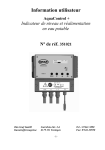
USER MANUAL AND TECHNICAL MANUAL
NOTE: This manual contains important information concerning safety and daily use as
well as maintenance instructions and should be stored for future use.
This manual is valid for all cabinets that are delivered after 2001.
Manufactured by:
KANMED AB
January 2004
PART NO: GE-1002-070/3
USER and TECHNICAL MANUAL KANMED Warming Cabinet GE-2-1370
Page 2 of 16
TABLE OF CONTENTS
1
2
3
4
5
6
7
8
9
10
11
12
SAFETY INSTRUCTIONS ..................................................................................................... 3
GENERAL DESCRIPTION .................................................................................................... 4
DESCRIPTION OF FUNCTION ............................................................................................. 4
TECHNICAL DATA ................................................................................................................ 5
UNPACKING AND PACKING LIST ....................................................................................... 6
INSTALLATION...................................................................................................................... 6
USING THE CABINET ........................................................................................................... 6
MAINTENANCE AND TROUBLE SHOOTING ...................................................................... 8
ACCESSORIES AND SPARE PARTS ................................................................................ 10
WARRANTY ..................................................................................................................... 11
CIRCUIT DIAGRAM FOR CABINETS DELIVERED UNTIL 2003.................................... 12
CIRCUIT DIAGRAM FOR CABINETS DELIVERED FROM 2004.................................... 13
USER and TECHNICAL MANUAL KANMED Warming Cabinet GE-2-1370
1
Page 3 of 16
SAFETY INSTRUCTIONS
INTENDED USE
KANMED Warning Cabinet GE-1380-XX is primarily intended for warming of Gel Pads,
blankets, fluids, up to a temperature of 42°C
KANMED Warning Cabinet shall be used according to this user manual and in accordance
with normal hospital routines.
GENERAL ADVICE
Adjust the cabinet so that it is correctly positioned, vertically and horizontally.
Secure the cabinet to the wall using the built in brackets at the top.
Never pull out all shelves/baskets at the same time. The cabinet can tilt forward if it is not
secured to the wall.
Take extra caution if the cabinet is mounted on wheels, especially when the cabinet is moved
around.
Note! If the cabinet is not secured to a wall, don’t’ pull out more than one shelf/basket at a
time.
Do not overload the shelves/basket - maximum 8 kilos per shelf. Max 2 pcs. of gel pads
(45x50x1.5) Max load of the basket is 20kg.
Do not overfill the top shelf - there must be at least 5 cm's free space to ensure air
circulation.
Don't block the ventilation holes at the inside rear of the cabinet.
EXPLANATION OF SYMBOLS
Consult Users Manual
O
OFF
I
ON
~
AC current
UP button, rises temperature
DOWN button, decreases temperature
SET button, for displaying desired temperature
USER and TECHNICAL MANUAL KANMED Warming Cabinet GE-2-1370
2
Page 4 of 16
GENERAL DESCRIPTION
THE CABINET
The cabinet is made of stainless steel and insulated in order to reduce heat loss to ambience
and to reduce noise. For the same reason the door is double glassed.
THE HEATING COMPARTMENT
Heating element, fan, thermostat, temperature regulator/indicator and electrical connections
are all placed on a "shelf" at the top of the cabinet. A spare fan is also included and mounted
in the heating compartment. The heating compartment is kept in place by a small screw that,
when loosened, allows the whole heating compartment to be pulled completely out to make
service quick and easy.
THE SHELVES-BASKETS
The shelves/baskets run on wheels and can be pulled fully out until they are automatically
stopped. To completely remove the shelves/basket for cleaning or repositioning, lift the front
of about 5 cm upwards and remove it. The shelves can carry maximum 8 kilos, basket 20 kg.
EXTRA SHELVES- EXTRA BASKETS
Extra shelves/baskets and rails are available.
Mount the rails with the screws supplied using the prepared mounting holes and then push
the shelf/basket in place by holding the front higher than the rear.
3
DESCRIPTION OF FUNCTION
The warming cabinet and its contents are warmed by warm air heated by a 1000 Watt
warming element. The hot air is circulated by a fan and distributed evenly through the outlets
at the rear of the cabinet. The temperature is regulated, by the temperature regulator T1 to
the set temperature.
Thermostat T2 functions as an over temperature protection and will take over the
temperature control in case the air temperature exceeds 45°C. At the same time the red
lamp on the front panel will be lit to indicate that there is a malfunction. Inside the heating
element there is an additional over temperature protection that is self-resetting. It will be
activated in case the fan stops or goes too slow.
On old versions of the cabinets a power switch at the door interrupts the power when the
door is opened. When restarted again the temperature goes back to the set temp as it was
before interrupted.
On the new cabinets this power switch is removed
NOTE: If the red over temperature lamp is lit there is an error that requires a technician.
USER and TECHNICAL MANUAL KANMED Warming Cabinet GE-2-1370
4
Page 5 of 16
TECHNICAL DATA
ELECTRICAL DATA:
Voltage
Power max.
Frequency
Fuses
220-240 Volt AC
1200 Watt *
50 -60 Hz
T 6,3A L250V
PHYSICAL DATA
Cabinet GE-1380
Height
Width
Dept
175 cm
66 cm
60 cm
GE-41500
Shelves inner measure
Height
Width
Dept
2 cm (edge)
52 cm
50 cm
Maximum load per shelf
8 kilos
GE-41600
Basket inner measure
Height
Width
Dept
13cm
52cm
50cm
Maximum load
20kg
TEMPERATURES
Working temperature
(Of circulating air)
Over temperature protection
Accuracy
Hysteresis (T2 overtemp.)
35°C – 42°C, selectable in steps of 1°C
Visual alarm 45°C
± 1°C
4°C max
WARMING CAPACITY
Warming of 10 gel pads GE-455015
45 x 50 x 1.5 cm from 22°C to 40°.
3 hours
MODE OF OPERATION
Designed for continuous use
CE - MARKING
According to 89/366/EEC and 93/68/EEC
(EN 60601-1-2, EN55011 (1991)
* The nominal effect of the heating element 1000 W. Due to the thermostat regulation the
average power consumption is about 400 W
USER and TECHNICAL MANUAL KANMED Warming Cabinet GE-2-1370
5
Page 6 of 16
UNPACKING AND PACKING LIST
The cabinet is when shipped from KANMED carefully packed. Check for damages and report
them immediately to your supplier. Damages reported after the cabinet has been brought
into use are not accepted.
See the enclosed unpacking instructions which are attached to the cabinet and marked
"Unpacking Instructions."
PACKING LIST
Description
Part no
Quantity
Warming Cabinet 175cm
Warming Cabinet 90cm
Warming Cabinet 175cm on wheelbase
Warming Cabinet 90cm on wheelbase
Manual
GE-1380
GE-1380-90
GE-1380-W
GE-1380-90-W
GE-1002-07X
1
6
1
INSTALLATION
Adjust the feet so that the cabinet is levelled.
Connect the cabinet to a grounded power outlet.
NOTE: Always secure the cabinets to a wall by using the built in top brackets to avoid
the risk of tipping forward at unfortunate circumstances.
7
USING THE CABINET
Open the door and switch on the Cabinet with the green power switch at the upper right side.
Check the set temperature and adjust if necessary according to 7.2
7.1
GENERAL ADVICE
The Cabinet is designed for continuous use and shall be left switched on in order to ensure
that the contents are always warm.
If 2 gel pads are placed on top of each other the warm up time is increased considerably. If
often more than 10 gel pads are to be warmed at the same time we recommend that you
order extra shelves. Avoid folding gels.
Max load on a shelf is 8kg in basket 20kg.
NOTE: Do not place blankets or other bulky stuff at the top shelf since it may block the
air intake and cause overheating in the heating element due to reduced air flow.
Ensure that there is at least 5-cm free space.
USER and TECHNICAL MANUAL KANMED Warming Cabinet GE-2-1370
7.2
Page 7 of 16
TEMPERATURE ADJUSTMENT AND INDICATION
The display shows the actual working temperature in the cabinet as long as the ON/OFF
switch is on and the door is closed.
The set temperature is indicated when the set button is pressed.
Every time the warming is switched on (ON/OFF or closing door), the set value is
automatically set to the set value that was valid at the previous switch off of the warming.
The working temperature can be selected in steps of 1oC within the range of 35 to 42oC.
Older version of regulator type ( 700-0464)
UP
DOWN
SET
UP
DOWN
OUT
Press set button to show the set (selected) temperature.
The set value is shown and the out lamp blinks as long as the set button is
pressed.
While the set button is pressed, the set value can be altered by pressing the UP
/ DOWN button.
Press for temperature rise
Press for temperature decrease.
Flashes as long as the set button is pressed.
Lights permanently while heating takes place (relay is closed)
Newer version of regulator (700-0659)
out
°F
°C
set
SET
Press set button to show the set (selected) temperature.
The set value is shown and the OUT lamp blinks for 2 sec. The set value can
be altered by pressing the UP / DOWN button.
UP
Press UP within 2 sec. for temperature rise until wished value is shown in the
display.
Press DOWN within 2sec. for temperature decrease until wished value is
shown in the display.
Down
USER and TECHNICAL MANUAL KANMED Warming Cabinet GE-2-1370
8
8.1
Page 8 of 16
MAINTENANCE AND TROUBLE SHOOTING
CLEANING
Clean and disinfect with normal detergents. If hepatitis or HIV is suspected then use stronger
disinfectants.
8.2
TEMPERATURE CONTROL/CALIBRATION
To be performed by a qualified technician only.
GENERAL INFORMATION
The working temperature is regulated by the temperature regulator T1 and the over
temperature protection by the sensors T2. When control, calibration of T1 and T2, their value
is compared to the value of an external precision thermometer. ( for example the KANMED
article Baywatch-01)
The sensor T2 can be adjusted through a hole in the bottom of the heating compartment.
The external control thermometer, with a precision temperature sensor, is to be placed
between two gel pads (GE-455015 or GE-255015) in the middle of the centre shelf.
Let the cabinet warm up properly (at least 12 hours if cold start) before attempting calibration.
8.2.1 TEMPERATURE REGULATION
INFORMATION ABOUT TEMPERATURE MEASUREMENT AND CALIBRATION
T1 is a powered microprocessor temperature regulator/indicator that has resolution of 1°C.
Corrections can be done through a series of pushing’s on the regulator buttons according to
the description below.
NOTE! To adjust the temperature T1 you have to have the door open. On older
cabinets equipped with a door switch the door switch S1 must be pressed with for
example some tape while you do the correction. Don’t forget to remove the tape when
you are finished.
PROCEDURE
Place the external control sensor as described under GENERAL INFORMATION above.
Start the warming and wait until the temperature is stable (at least 12 hours). Compare the
external control thermometer with the set temperature and if the deviation is bigger than +/1°C adjust as follows.
Old regulator type (700-0464)
1. Press UP and DOWN exactly simultaneously (only one beep may be heard, if you
don’t succeed- .repeat) and keep pressed for 5 sec until the indicator display shows
“PA”
2. Press UP or DOWN until the display shows “1”
3. Press SET and at the same time UP or DOWN to compensate the noted temperature
difference, one press gives a adjustment of 1°C.
1. For example: The display shows 42°C but the external control temperature shows
39°C. The difference is -3°C, to compensate this difference press three times on
DOWN button (the earlier value will drop with 3 degrees)
4. Store the new calibrated value by pressing UP and DOWN simultaneously (only one
beep may be heard, if you don’t succeed- .repeat)
5. Measure the temperature again and control that T1: s shown value compares to that
of the external thermometer.
If necessary dismount the locking of the door switch S1
USER and TECHNICAL MANUAL KANMED Warming Cabinet GE-2-1370
Page 9 of 16
New regulator type ( 700-0659)
1. Press UP and DOWN exactly simultaneously (only one beep may be heard, if you
don’t succeed- .repeat) and keep buttons pressed for 5 sec until the indicator display
shows “PA”
2. Press one time on UP, then the display shows ┌┘1,( parameter for calibration of
sensors)
3. Press SET once and within 2 sec on UP or DOWN to compensate for the noted
temperature difference, one press gives the change of 1°C.
For example: The display shows 42°C but the external control temperature shows
39°C. The difference is -3°C, to compensate this difference press three times on
DOWN button (the earlier value will drop with 3 degrees)
4. Store the new calibrated value by pressing UP and DOWN simultaneously (only one
beep may be heard, if you don’t succeed- .repeat) and keep pressed for 5 sec until
the indicator display shows the actual temperature.
5. Make a new measurement of the temperature and control that T1:s shown value
compares to that of the external thermometer
8.2.2 OVER TEMPERATURE
INFORMATION ABOUT TEMPERATURE MEASUREMENT AND CALIBRATION
The temperature sensor T2 is a capillary thermostat. In the KANMED cabinet its hysteretic is
4°C max. When delivered T2 is set to 2°C above the maximum value of T1 ( 42°C). The
activation of T2 is identified by a clear click sound as well as by the red over temperature
lamp is lit
The procedure described below is a simplified method to check and if necessary adjust T2
PROCEDURE
1. First check the temperature regulation as described under 8.2.1 above. Set the
regulator T1 on max .setting (42°C)
If the cabinet is cold, let it first get proper warm for at least 12 hours, before the
measure/calibration is done. Check that the cabinet warms to the max temperature
setting.
2. Adjust the set temperature by turning T2: s adjustment screw (you find it through the
hole on the underneath of the shelve) with a screwdriver. Turn the adjustment screw
fully clockwise (+). Now Turn counter clockwise back to activation (one click sounds),
turn again clockwise past the activation point in tiny steps ( a new click sounds)
3. Control that you don’t activate the over temperature indication when run the cabinet in
normal operation ( with T1 prepared on 42°C ) If this should happen you have to
repeat the procedure and set T2:s activation point a bit higher
USER and TECHNICAL MANUAL KANMED Warming Cabinet GE-2-1370
8.3
Page 10 of 16
TROUBLE SHOOTING
If the warming is not starting, check as follows:
• Power cable connected (UK only - and plug fuse OK)?
• Power in the wall socket?
• Cabinet fuses OK?
• Power Switch on (If power is OK it will show a green light)
• For older Cabinets, is the door properly closed? The door starts the warming by pressing
in the safety switch located on the upper left side of the front panel. Pressing in this
switch with your finger should start the warming if above switch is OK?
• Is the fan rotating? It shall start as soon as you press in the safety switch as mentioned
above. If it is not rotating, making a strange noise or rotates slowly it must be changed.
• Is the heating element getting too warm? The heating element has a self resetting over
temperature protection (85°C) and two 1000W heating wire loops. Only one of the 1000W
heating wires is being used. If it breaks, the second can be used instead. If the
temperature protection cuts out the element frequently, there is not enough airflow
through the element.
• Check the fan and that the air intake under the heating compartment is not blocked.
NOTE: All checking that involves opening the heating compartment must be done by a
qualified technician.
9
ACCESSORIES AND SPARE PARTS
ACCESSORIES
Part no
GE-41500
GE-41600
SPARE PARTS
Part no
700-0180
700-0181
700-0183
700-0184
700-0457
700-0456
700-0464
Description
Shelf
Basket
Quantity
1
1
Pos. in drawing
Description
S2
Mains power switch
S1
Safety switch at door
M1
Fan
HE
Heating Element
G1
Temperature sensor
Tr
Transformer
T1
Temperature regulator
Quantity
1
1(old cabinets)
1
1
1
1
1(earlier
T1
1(later model)
1(later model)
1(later model)
1
1
1
1
1
2
2m
1
1
1
1
10
10
model)
700-0659
700-0660
700-0661
700-0185
700-0187
700-0201
700-0211
700-0202
700-0203
700-0204
700-0205
700-0206
700-0453
700-0208
700-0209
700-0460
T2
L1
F1
F2
Temperature regulator
Diode 1N4005
Capacitor 100 µF 63V
Thermostat
Red lamp
Glass for door to cabinet 175 cm high
Glass for door to cabinet 90 cm high
Handle for door
Wall mounting bracket
Door gasket
Set of screws
Foot for cabinet
Front panel label WC 1002, adhesive
Fuse holder
Fuse T6,3A
Fuse T50mA
USER and TECHNICAL MANUAL KANMED Warming Cabinet GE-2-1370
10
Page 11 of 16
WARRANTY
KANMED warrants the purchaser that the Warming Cabinet is free from defects in material
and workmanship for a period of 12 month from the date of delivery.
The sole obligation of KANMED with respect to any such defect is limited to the repair with
new or re-manufactured parts or, at the discretion of KANMED, replacement of the
equipment or refunding of the purchase price.
This warranty shall not apply if the product has been modified, adjusted or repaired other
than by KANMED or by organisations authorised by KANMED or modified, adjusted or
repaired not in accordance with written instructions provided by KANMED or if the equipment
has been subject to misuse, negligence or accident.
These warranties are made on the condition that prompt notification of a defect is given to
KANMED or its authorised dealers within the warranty period.
KANMED shall have the sole right to determine whether a defect exists.
KANMED shall not in any case be liable for special or consequential damages arising from
the breach of warranty, breach of contract, negligence or any other legal theory.
USER and TECHNICAL MANUAL KANMED Warming Cabinet GE-2-1370
11
1.
2.
3.
4.
5.
6.
7.
8.
9.
10.
11.
12.
13.
Page 12 of 16
CIRCUIT DIAGRAM for cabinets delivered until 2003
F1
S1
S2
T1
T2
L1
M1
G1
TR
RE
HE
F2
Connection socket
Fuse 6,3 A
Safety switch activated by the door
Mains switch
Temperature regulator
Over temperature protection
Warning lamp red - over temperature warning
Fan
Temperature sensor
Transformer
Relays
Heating element
Fuse
USER and TECHNICAL MANUAL KANMED Warming Cabinet GE-2-1370
Page 13 of 16
12
CIRCUIT DIAGRAM for cabinets delivered from 2004
1.
2. F1
Connection socket
Fuse 6,3A
4. S2
5. T1
6. T2
7. L1
8. M1
9. G1
10. TR
11. RE
12. HE
13. F2
Main switch
Temperature regulator
Over temperature protection
Warning lamp red – over temperature warning
Fan
Temperature sensor
Transformer
Relays
Heating element
Fuses 50mA
USER and TECHNICAL MANUAL KANMED Warming Cabinet GE-2-1370
Page 14 of 16
USER and TECHNICAL MANUAL KANMED Warming Cabinet GE-2-1370
Page 15 of 16
USER and TECHNICAL MANUAL KANMED Warming Cabinet GE-2-1370
KanMed AB
Gårdsfogdevägen 18B
S-168 66 BROMMA
SWEDEN
Tel +46 (0)8 564 80 630
Fax +46 (0)8 564 80 639
E-Mail: [email protected]
Home page: www.KANMED.se
DISTRIBUTED BY:
Page 16 of 16