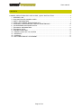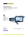
1
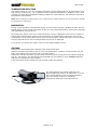
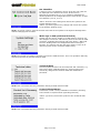
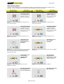
User Manual
KANMED Operatherm OP3™
User manual, art no OP3-070/3
2010-02-09
0413
Caution
Incorrect use of Heating
equipment may cause
serious injury.
Please read this manual
thoroughly.
Manufactured by:
KANMED AB
Gårdsfogdevägen 18B
SE-16866 BROMMA
SWEDEN
www.kanmed.se
This manual is valid for KANMED Operatherm OP3 system serial
number 0001-08 and above, with Software version 1.0 or higher.
Subject to changes.
User manual
CONTENTS
KANMED OPERATHERM OP3 USER GUIDE, QUICK INSTRUCTION…..…………..…………………..3
1 INTENDED USE ....................................................................................................................................... 4
2 EXPLANATION OF SYMBOLS USED .................................................................................................. 4
3 SAFETY INFORMATION ........................................................................................................................ 5
4 USING THE KANMED OPERATHERM OP3 ....................................................................................... 6
5 CLEANING, CHECKS BEFORE USE AND MAINTENANCE ......................................................... 10
6 ACCESSORIES AND SPARE PARTS ............................................................................................... 11
7 TECHNICAL INFORMATION............................................................................................................... 12
8 TECHNICAL DATA................................................................................................................................. 15
9 TROUBLE SHOOTING.......................................................................................................................... 16
10 ANNUAL CHECK OF THE SYSTEM ................................................................................................. 20
11 WARRANTY........................................................................................................................................... 21
12 DISPOSAL............................................................................................................................................. 21
13 EMC COMPATIBILITY STATEMENT............................................................................................... 21
Page 2 of 24
User manual
KANMED Operatherm OP3 User Guide Quick instruction
Intended Use
The KANMED Operatherm OP3 patient warming system is designed to be used pre-, per- and post
operatively. It must be used according to this manual. The system is intended to reduce the risk of
hypothermia. It is not intended for home use. It should only be operated by qualified medical
personnel that have undergone proper product training.
Caution! Incorrect use of Heating equipment may cause serious injury. The user manual must be
read completely before use.
Preparation
Position the Heating Pad on the operating table. Cover the Heating Pad with pre-warmed Kanmed
Gel Pads.
Connect the Heating Pad cable to the front connector on the Control Unit.
Connect the power cable to a mains power outlet with protective grounding. The green LED on the
Control unit is lit when mains power has been connected. After mains power has been connected
the system program will load and it will take approximately 30 sec before the system is ready to be
started (when the stand-by screen is displayed).
Start/Stop
Press the button on the front panel to start. Make sure that the automatic self test is properly
performed. When prompted, answer by selecting the “YES” option, confirming that the Heating Pad
is covered by Kanmed Gel Pads. If the “No” option is selected, the maximum temperature will be
limited to 37°C.
The system is set to stand-by by pressing the start/stop button for five seconds. When in stand-by,
the mains power may be removed. (An accidentally triggered power alarm can be reset by pressing
the on/off button for two seconds).
Temperature settings
Default temperature setting is 37°C. The average temperature of the Heating Pad can be set
between 33°C and 39°C by pressing the [‹] or [›] buttons until desired temperature is displayed.
39°C is the recommended setting, suitable for most situations but should be attuned to the
patient’s requirements.
Note: When temperature settings above 37°C or below 35°C are selected, the unit will alert the
operator by prompting for confirmation.
Caution! Always monitor the patient’s actual body temperature with a reliable method.
Safety information
User Manual
Read the whole manual carefully before using the equipment.
Reduced Blood Flow
Parts of the body that have reduced or no blood flow should never be warmed.
Set the system to stand-by well ahead of a blood vessel shut off.
Error Codes
If an error is detected by the system an acoustic alarm is received and a code
is displayed on the Control Unit as “Code XXX”.
The meaning of the error code is also indicated by an icon. Full information
about the error is found in the user manual.
System Malfunction
If the Operatherm OP3 self test does not perform correctly, the function
supervision has displayed an alarm or error message or the Control Unit has
received mechanical damage, it should then be examined by a qualified
technician before being used. If you experience that the Operatherm OP3 is
not operating properly, immediately turn the system off and consult a
qualified technician for advice.
Page 3 of 24
User manual
User Manual
1
INTENDED USE
The KANMED Operatherm OP3 patient warming system is designed to be used pre-, per- and post
operatively. It must be used according to this manual. The system is intended to reduce the risk of
hypothermia. It is not intended for home use. It may only be operated by qualified medical staff
that has undergone proper product training according to the hospital routine.
Latest version of the user manual and information about accessories can be found at
www.Kanmed.se
2
EXPLANATION OF SYMBOLS USED
(Green LED) Mains Power indicator
Increase temperature, or change
highlighted selection in MENU
Start/Stop button
Decrease temperature, or change
highlighted selection in MENU
(Red/Orange LED) Error Indicator
MENU
Select main MENU, or change
highlighted selection in MENU
Alarm Silence
Select alternative display mode,
or change highlighted selection in
MENU
Please read the instruction manual
ENTER, select highlighted item in
MENU.
Risk of explosion in the presence of
inflammable gases.
Earth potential equalisation
connection point
Safety class BF, Defibrillator safe
IPX7 Water tight Heating Pad
Fulfils MDD93/42/ECC. (Notified Body 0413= Intertek Semko AB, Sweden)
Page 4 of 24
User manual
3
SAFETY INFORMATION
Warnings
•
•
•
•
•
•
•
Proper Use. To ensure optimal performance and to prevent incorrect use, the user manual must be read
completely before the system is being used.
System Malfunction. If the Operatherm OP3 self test does not perform correctly or the function
supervision has displayed an alarm or error message or the Control Unit has received mechanical damage,
it must be examined by a qualified technician before being used. If you suspect that the Operatherm OP3 is
not operating properly, immediately consult a qualified technician for advice.
Restricted Blood Circulation. Heat supply to tissue with no, or restricted blood circulation may result in
serious tissue damage. Place the Heating Pad where blood circulation is maintained alternatively turn the
Operatherm OP3 system off during the period of the restriction.
Never use the Operatherm OP3 system without Kanmed GEL Pads! Ensure that there are no
wrinkled materials under the patient. Any collection of fluid under the patient, especially disinfecting
agents, can cause skin irritation.
Electrical Hazard The system must always be connected to a mains power outlet with proper protective
grounding. Always remove the mains power cable before cleaning the Control Unit. NOTE: The OP3 may
not be interfaced with any other electrical system. If this is done a new “system” is created per definition,
and the safety classification of the OP3 may be effected.
Body temperature. When using the Operatherm OP3 system, the patient’s actual body temperature (core
temperature) should be constantly monitored by a reliable method.
Dropped or otherwise possibly damaged. If the Operatherm OP3 Control Unit had fallen to the floor or
has been subjected to other possible damage it must be examined by a technician before being used.
Caution
•
•
•
•
•
•
•
•
•
•
•
•
Gel. The OP3 Heating Pad must always be completely covered by Kanmed Gel Pads. The Gel increases the
contact surface and thereby the amount of energy transferred to the patient. It is important to pre-heat
Gel Pads in advance because cold Gel Pads will drain energy from the patient.
Modifications. Un-authorised personnel are not allowed to open the Control Unit or the Heating Pad
Connector. No modifications of the system, of any kind, are allowed since it will void the safety certification
of the system and may seriously endanger patient safety. Only original parts may be used. The Heating
Pad cable may not be altered in length or repaired in any way. If damaged, the complete Heating Pad must
be replaced.
Temperature setting. If the OR-table surface is hard, blood pressure is low i.e. bad circulation, old
patients, patients with diabetes, etc. 37°C should be the highest temperature setting used. For
extraordinarily long operations and for patients sensitive to static pressure (e.g. diabetics), the
combination of immobility, skin pressure and warming may prove a bad combination. You may consider not
using the Operatherm OP3 system in these cases. Consider Kanmed WarmCloud instead.
Temperature reading. Observe that the indicated temperature is a calculated average temperature value
and may differ somewhat from local spot temperature readings of the Heating Pad surface.
Children and pre-term babies. Patients with low body mass, particularly pre-term babies are easily
influenced by the surrounding temperature. They get cold fast and may get fever if over-heated. Be
particularly careful when temperature settings above 37°C are being selected.
Compatibility. Only KANMED OP3 series Heating Pads can be used with Operatherm OP3 Control Unit. The
Operatherm OP3 system is NOT compatible with KANMED OP200 series Heating Pads.
EMC. Operatherm OP3 needs to be installed and put into service according to the EMC information
provided. (Detailed EMC information can be downloaded from www.Kanmed.se)
DIATHERMY equipment and Defibrillators. Under normal circumstances the Operatherm OP3 is not
disturbed by this type of equipment. However, if the diathermy or defibrillation is set at very high output
levels, the Operatherm OP3 might go into alarm state. In such a case, restart the system and observe that
the self test is being performed correctly. Note that the Control Unit housing is electrically connected to
earth.
ECG disturbance. Under unfavourable conditions there is a risk that interference may occur on ECG
traces. This may occur if the ECG electrodes are not being applied strictly to the manufactures instructions
or if the Operatherm OP3 Heating Pad is positioned upside down (text side facing down).
MRI cameras. The system is not designed for use with MRI cameras.
Heating Pad storage. The Heating Pad should be stored using the Pad Hanger for wall mount that is
included in all control unit deliveries or rolled to a diameter not less than 150mm. Do not bend or fold the
Heating Pad in a way that sharp crease arises.
Cleaning. Users should not use cleaning or decontamination methods different from those recommended
by Kanmed without first checking with Kanmed that the proposed methods will not damage the equipment.
Page 5 of 24
User manual
4
USING THE KANMED OPERATHERM OP3
THE CONTROL UNIT
The Control Unit contains a microprocessor based heating control system that regulates the
temperature of each of the elements (heating zones) in the Heating Pad. The temperature is
continuously monitored and the calculated average temperature of the Heating Pad is displayed.
Automatic Self Test
Every time the Operatherm is switched on it will perform an automatic self-test of all functions
including the internal safety-circuit. If an error is detected, the Operatherm OP3 will not start the
heating, the acoustic alarm will sound and the type of error is being indicated by the display.
Warning! Never use the system if the self test does not perform correctly!
Front Panel Layout
1.
2.
3.
4.
5.
6.
7.
Display
Navigation Pad
Heating Pad connector
Alarm indication LED
Power indication LED
Alarm reset button
ON/OFF button
Rear Panel Layout
The rear-panel contains information
about manufacturer, part number,
serial number, voltage, etc. Mains
power cord, and optional earth
potential equalisation grounding is
also connected here.
Page 6 of 24
User manual
HEATING PAD
The 104 cm long standard Heating Pad OP3-104 (and the 150 cm Pad OP3-150) consists of eight
individual heating zones (elements), and the Heating Pads OP3-063 and OP3-050 of four zones.
Each zone is temperature regulated separately. Thanks to this unique feature the heat is supplied
to the part of the Pad where it is most needed.
The individual elements are insulated from each other and embedded in a Mylar foil. They are
hermetically sealed into the soft hospital grade plastic foil.
The Heating Pad is watertight and easy to clean. Element voltage is only about 30 Volts DC.
The Pad is connected to the front of the Control Unit. The Pad Connector contains a flash memory
for calibration parameters of the elements, logged information of the previous sessions and an
independent safety circuit.
PREPARATION
The Heating Pad
Place the Heating Pad on the OR-table with the printed side up and make sure it is not folded.
Cover the Heating Pad completely with pre-heated Kanmed Gel Pads and a bed-sheet.
Gel Pad
GE-455015
(50 x 45 x 1,3 cm)
Fits the OP3-104 and OP3-150 Heating Pads.
Use two Kanmed Gel Pads on OP3-104 and three on OP3-150.
Gel Pad
Gel Pad
GE-436315
GE-305015
(63 x 43 x 1,3 cm)
(50 x 30 x 1,5 cm)
Fits the Heating Pad OP3-063
Fits Heating Pad OP3-050
Connect the Heating Pad to the Control Unit and make sure that the connector engages fully.
Mains Connection
Connect the power cable to a mains power outlet with protective grounding. The green LED on the
Control Unit is flashing when mains power has been connected. After mains power has been
connected the computer will automatically boot (load the software) and it will take approximately
30 sec before the system is ready to be started (when the stand-by screen is displayed).
Location of the Control Unit
Locate the Control Unit where its display can be easily observed. It can be hung on its handle. Note
that the handle and the enclosure are electrically connected to protective earth.
START
Switch the unit on by pressing the start/stop button on the front panel. Observe that a correct self
test is executed. Confirm that Kanmed Gel Pads have been properly applied by selecting “√” (press
[›] button and “Enter”). The heating will now start automatically at 37°C. During the first 10
minutes after start, the Operatherm will perform a “power boost” cycle permitting maximum output
power to be fed to the Heating Pad. After 10 minutes, the maximum output power will be reduced.
Note 1: If the Operatherm OP3 does not behave as described above it shall not be used and must be examined
by a qualified technician.
Note 2: During the first 10 minutes after start, the Operatherm will perform a “power boost” cycle permitting
maximum output power (approximately 180 W) to be fed to the Heating Pad. After 10 minutes, maximum
output power will be limited. Different types of Pads have different power limits.
STOP
Set the system to stand-by by keeping the start/stop button on the front panel pressed for more
than 5 sec. In stand-by mode the mains power may be removed for a complete power down.
Note: The Operatherm OP3 is designed to be left running continuously, so it can keep the Gel Pads heated and
be ready for use at any time.
Page 7 of 24
User manual
TEMPERATURE SELECTION
The default setting is 37°C. The average temperature of the Heating Pad can be set between 33°C
and 39°C by pressing the [‹] or [›] buttons until the desired temperature is displayed. 39°C is the
normally recommended temperature setting suitable for most situations, but should be attuned to
the patient’s requirements.
Note: When temperature settings above 37°C or below 35°C are being selected, the unit will alert the operator
by prompting for confirmation.
NAVIGATION
During normal operation, two different display screens can be selected. The OP3 will start with the
default display screen giving information of the set- and actual temperature, actual power emission
and elapsed time since power on.
By pressing the “down arrow” the “Temp and Power” screen is displayed. This screen is useful for
monitoring the distribution of power and temperature to the different temperature zones of the
Heating Pad, and for information of how much energy has been emitted during the current session.
The set temperature can not be changed when this screen is displayed.
If “up arrow” is pressed, the system returns to the default display screen.
GELPADS
Always cover the Heating Pad completely with Kanmed Gel Pads.
Always use Kanmed Gel Pads to get an even heat distribution, a greater contact surface with the
body of the patient and reduce the risk of pressure sores.
Always pre heat the Gel Pads. Cold Gel Pads will actually drain energy from the patient during the
first 20 - 40 minutes. The Gel Pads should preferably be pre-heated to 42°C (KANMED Warming
Cabinets are designed for this purpose).
A thin bed-sheet can be placed over the Gel Pads (under the patient).
The most efficient pre-heating method is the
Kanmed Warming Cabinet. An alternative, is to roll
the Gel Pads together with the Heating Pad and
leave the system running on maximum
temperature setting for more than 2 hours.
Page 8 of 24
User manual
EXPLANATION OF THE DISPLAY SCREENS
The system has a screen saver function, causing the display to dim the back light 30 minutes after
pressing any button. This function is common for all display screens. In order to “wake” the system
up from screen saving mode, just press any button.
Start Up
Shown when the mains power has been connected.
Start Up screen
This screen is displayed shortly after the unit has been
connected to mains power, and is displayed during the time
the computer is booting (about 20 sec.), followed by a blank
screen during 10 sec. After the blank screen the system will go
to standby.
Stand by screen
This screen is displayed when system is in standby, and is
ready to be switched on (by pressing the on/off button), or to
access the technical menu by pressing “menu”.
To shut down the system completely, the mains power cord
must be removed. This is only doable when the system is in
stand-by, (otherwise the power loss alarm will be triggered).
Normal Operation
Functions accessed after pressing the on/off button when in standby mode.
Self test screen
The self test will start automatically when the on/off button is
pressed. Information of diagnostic tests being performed is
displayed (checked parts turning green if found OK). If an
error is detected, an error message will be displayed (see
chapter trouble shooting).
The alarm LED will flash orange/red rapidly during the Heating
Pad test. A short acoustic alarm signal will sound when the
self test is completed.
GEL confirmation
screen
Prompting the operator to
confirm that the Kanmed
Gel Pads are properly
applied. Positive response
enables the use of
temperature settings
above 37°C.
NOTE: When positively confirmed by moving the highlighted selection to the green “√” (using the
[‹] or [›] buttons) and pressing “Enter”, the Default screen will be viewed and the system will start
operating at the default temperature setting of 37°C. Higher temperature settings are permitted.
If “X” is selected, the system will start operating at the default temperature setting of 37°C.
Temperature setting will now be limited to max 37°C.
Page 9 of 24
User manual
Default display
Information about:
1. Elapsed time since start-up
2. Heating Pad power
3. Heating Pad temperature
4. Set (desired) Heating Pad temperature
5. Gel indicator (icon present if positively confirmed)
6. Status bar
Temperature settings
When temperature settings
below 35°C or above 37°C
are being selected, the unit
will alert the operator by
prompting for confirmation
(operator to press “Enter”)
TIPS: An extra press on the [‹] button also acts as “enter” when low temp setting is selected and
[›] button when high temp setting is selected.
Power and energy display
By pressing the “down arrow”, the system displays
information about:
1. P = Current Heating Pad power.
2. E = Energy output from start-up
3. Heating Pad temperature (average value).
4. Set temperature
5. Individual temp and power information of each of the 8
Heating elements in the Pad.
A new press on the “down arrow” or the “up arrow” returns
the system to the default operating screen.
NOTE: The set temperature can not be changed when this screen is displayed. Pls. return the
system to the default display by pressing the “down arrow” if set temperature is to be changed.
5
CLEANING, CHECKS BEFORE USE AND MAINTENANCE
Cleaning / Disinfecting
Always unplug mains power cord before any maintenance procedure. Wipe off the Control Unit with
a moist cloth and if necessary use normal hospital cleaning agent.
Clean the watertight Heating Pad with soap or your usual cleaning agent. Disinfect the Pad with
alcohol or any other commonly used disinfectant.
NOTE: Do not autoclave the Pad. Do not submerge the connector in any liquid.
Checks before use
Check that all parts are clean and in god condition. Check that the unit performs a correct self test
at start. If error codes appear and can not be eliminated with the suggestions given in the trouble
shooting section of this document, then it should be notified to Technical staff. Note: If any part of
the system has received mechanical damage, it should always be checked and correct system
function verified by technical staff.
Maintenance
Kanmed Operatherm OP3 does not require any special maintenance apart from what is described in
the technical section of this manual.
Storage The Heating Pad shall be stored hanging with the Pad Hanger or lying flat. Avoid folding.
Page 10 of 24
User manual
6
ACCESSORIES
Article no.
Product
OP3-022
Control Unit
OP3-115
OP3-100
Control Unit
Control Unit
OP3-104
104 cm Heating Pad
OP3-150
150 cm Heating Pad
OP3-063
Short Heating Pad
OP3-050
Small Heating Pad
GE-455015
Gel Pad
GE-305015
Gel Pad
GE-436315
Gel Pad
OP3-005
OP3-070
OP3-079
OP3-099
Pad Hanger
User manual *
Service Manual
Calibration Adapter
Comment
Includes Pad Hanger, mains cord and instruction manual.
Factory set to 220-240V AC, 50/60 Hz
As above, but set to 100-120 AC, 50/60 Hz
As above, but set to 100V AC, 50/60 Hz
1040 x 450 mm. X-Ray translucent. Standard Heating
Pad. Fits most patients. Requires two standard Kanmed
Gel Pads.
1500 x 450 mm. X-Ray translucent. Requires three
standard Kanmed Gel Pads.
630 x 430 mm. X-Ray translucent. Must always be used
with the Gel Pad no GE-436315. For small children during
surgery, post operative warming, under radiant heaters,
on resuscitation tables.
500 x 300 mm. X-Ray translucent. Must always be used
with the Gel Pad no GE-305015. For small children during
surgery, post operative warming, under radiant heaters,
on resuscitation tables and in baby cribs.
500 x 450 x 13 mm. Standard Gel Pad.
300 x 500 x 15 mm. Fits perfectly over Heating Pad OP3050. Equipped with a pocket for the Heating Pad
630 x 430 x 13 mm. Fits perfectly over Heating Pad OP3063.
Wall mounted hanger for the Heating Pads.
English.
English.
For checking the Control Unit calibration.
SPARE PARTS
Article no.
Product
Comment
700-0751
700-0766
Rubber Frame
Rear label
PAD Connector
casing
CU Front label
CPU unit incl front
Main board
Power board
Power transformer
Power transformer
Mains power intake
Connector Saver
CU Rear panel
Cable kit
CU Handle
CU Bottom plate
CU Cabinet
Elastosil A07, 90ml
NOTE: Two pcs per unit is required.
700-0748
700-0765
300-001
300-002
300-003
300-004
300-005
300-006
300-007
300-008
300-011
300-012
300-013
300-014
700-0255
Plastic pad-connector housing (top/bottom) incl. screws.
(OP303-1 Display and Computer board)
(Op303-2)
(OP303-3)
(the large power transformer, 2 x 28,6 V 300 VA)
(electronics power supply transformer, 10,3 V 9 VA)
With RF filter
37 pin F/F
excl. label
Internal control unit cable kit
(naked cabinet)
Silicon based adhesive for fixing the rubber frames.
* Latest version of the manual can be downloaded from www.Kanmed.se
For the latest information about accessories, please visit www.Kanmed.se or contact your
local dealer.
Page 11 of 24
User manual
7
TECHNICAL INFORMATION
The Control Unit contains a microprocessor based heating control system that regulates the
temperature of each of the 8 elements (heating zones) of the Heating Pad. The temperature is
continuously monitored and the calculated average temperature of the Heating Pad is displayed.
The safety system in the Control Unit is continuously monitoring the main power, internal voltages,
running parameters, the Pad condition and the behaviour of each element.
Two autonomous safety circuits, totally independent of the microprocessor based operating system,
can at any time stop the warming, should conditions occur that can cause over temperature.
If a fault is detected, the Control Unit will alarm visually and acoustically and switch off the heating.
The type of error is indicated on the alarm display. A description of the error codes are found under
the chapter “Trouble Shooting”.
“MENU”
This function is accessed if the “Menu” (up arrow) button is pressed when the unit is in stand by
mode. This menu or these functions are not available during normal operation of the system. They
are exclusively designed for system set-up or technical function control.
Main Menu screen
Top menu. Navigate by pressing the “up arrow” or “down
arrow” to highlight the desired action and press “enter”.
EXIT returns the system to stand-by mode.
NOTE: “up arrow” (menu) exits the function and returns the system to stand-by mode.
System Settings
Navigate by pressing the “up arrow” or “down arrow” to
highlight the desired action and press “enter”.
EXIT returns the system to the Main Menu.
NOTE: “up arrow” (menu) exits the function and returns the system to the Main Menu.
Set Time and date
Date will be set on the format YYYY-MM-DD and time on the 24
hour format HH-MM-SS.
Navigate by pressing the [‹] or [›] buttons to highlight the
desired digit to be changed and press “down arrow” to alter
the value of the digit.
“Enter” saves the new setting and returns the system to the
System Settings menu.
“Menu” (up arrow) ignores any change and returns the system
to the System Settings menu.
NOTE: “up arrow” (menu) exits the function and returns the system to the System Settings menu
without changing the time or date.
Page 12 of 24
User manual
Set Identifier
A name of up to 10 characters can be given the unit (and will
be displayed in the bottom left corner of the screen).
Navigate by pressing the [‹] or [›] buttons to highlight the
desired position to be changed and press “down arrow” to alter
the character (A to Z _0 to 9)
“Enter” saves the new setting and returns the system to the
System Settings menu.
“Menu” (up arrow) ignores any change and returns the system
to the System Settings menu.
NOTE: “up arrow” (menu) exits the function and returns the system to the System Settings Menu
without changing the set name.
Write logs to USB (technical function)
System log files can be written to a USB memory stick for offline analyzes. Connect a USB memory stick to the internal USB
connector, highlight this function and press “Enter”. Wait until
the text “Writing Data” has disappeared before exiting the
function. The Control Unit will now have written a copy of its
internal log files to the connected USB memory.
NOTE: The Control Unit must be opened to access the USB connector. This is an operation that only
shall be performed by trained technical staff.
Technical Data
Several system functions can be monitored and controlled, e.g.
SW version data, calibration data etc. These functions are
exclusively designed for technical staff and maintenance
personnel.
NOTE: This is functions that only should be used by trained technical staff.
Control Unit Summary
Information of SW version, Calibration information, Running
hours and No of system starts (operating sessions)
“Menu” (up arrow) returns the system to the Technical data
menu.
NOTE: This is functions that only should be used by trained technical staff.
Page 13 of 24
User manual
Control Unit Calibration Data
Factory set Calibration values for each of the 8 channels.
“Menu” (up arrow) returns the system to the Technical data
menu.
NOTE: This is functions that only should be used by trained technical staff.
Heating Pad Data Summary
Information about the connected Pad.
SW version, Calibration information, Running hours and No of
starts (operating sessions).
“Menu” (up arrow) returns the system to the Technical data
menu.
NOTE: This is functions that only should be used by trained technical staff.
Heating Pad Calibration Data
Information about the connected Pad.
Factory set Calibration values for each of the 8 elements.
“Menu” (up arrow) returns the system to the Technical data
menu.
NOTE: This is functions that only should be used by trained technical staff.
System Measurements
This function measures each of the eight channels separately
for deep analyze of the system measurement accuracy and the
condition of each of the elements in the connected HeatingPad.
Press the [‹] or [›] buttons to change the channel to study.
“Menu” (up arrow) returns the system to the Technical data
menu.
NOTE: This is functions that only should be used by trained technical staff.
Log Data
Information about the latest session.
Press the [‹] or [›] buttons to change the log to study.
“Menu” (up arrow) returns the system to the Main menu.
Page 14 of 24
User manual
8
TECHNICAL DATA
Control Unit
Voltage
Frequency
Power consumption
Temperature range
Temperature accuracy
Resolution
Over-temperature alarm level
Dimensions
Weight
Mode of operation
Art. no: OP3-022
Internally selectable;
100 V AC, 110-120 V AC, 220-240 V AC
50/60 Hz
285 VA (max)
33°C to 39°C in steps of 1°C
Better than ±1°C
1°C (Display resolution 0.1°C)
41.0°C ± 0.5°C
L 255 mm, W 150 mm, H 120 mm.
6 kg
Continuous
Common for all Heating Pads
Voltage
Length of cable
Water protection
Surface, electrical properties
30 V DC
2900 mm
Watertight, except for connector
Not electrical conductive
Heating Pad Standard (104cm)
No. of elements:
Max Power
Dimension
Weight
Art. no: OP3-104
8
200 W (8 x 25 W)
L 1040 mm, W 450mm, H 3 mm
2 kg
Heating Pad Long (150cm)
No. of elements:
Power
Dimension
Weight
Art. no: OP3-150
8
200 Watt (8 x 25W)
L 1500 mm, W 450 mm, H 3 mm
2,6kg
Heating Pad Short (63cm)
No. of elements:
Power
Dimension
Weight
Art. no: OP3-063
4
100 W (4 x 25W)
L 630 mm, W 430 mm, H 3 mm
1,6 kg
Heating Pad small (50cm)
No. of elements:
Power
Dimension
Weight
Art. no: OP3-050
4
100 W (4 x 25W)
L 500 mm, W 300 mm, H 3 mm
1,1 kg
Heating up time
Elements inside the Heating Pad
Heating Pad surface
about 8-10 minutes from 20°C to 37°C
about 25 minutes from 20°C when tested under
conditions of “ADEQUATE HEAT DISCHARGE”
in (IEC601-2-35)
Environment
Operating temperature
Shipping and storage
Humidity
+15°C to + 40°C
- 20°C to + 60°C
10% to 85% RH non condensing
Safety Standards
Protection type
Protection class
MDD classification
EN60601-1, EN60601-1-2, IEC60601-2-35
BF, Defibrillator safe
Class I
Class IIb
Page 15 of 24
User manual
9
TROUBLE SHOOTING
Function Supervision and Alarms
Apart from a complete self test when the system is turned on, (where all vital parts and safety
functions are being tested), the Operatherm OP3 supervises the function of the system during
normal operation and will render alarm or alert for any of the following fault conditions:
•
Incorrect temperature (e.g. high or low temperature alarm)
•
Heating Pad error (defective Heating Pad or to much energy being fed to the Pad)
•
Control Unit error (internal error detected).
•
Power Failure. (In case of a mains power failure, the Operatherm alarms by flashing the power
indication LED and sounding the beeper intermittently. The power failure alarm is kept active
for at least 10 min. The power alarm can be silenced by the operator by pressing the on/off
button for about 2 seconds).
For added safety against over-temperature due to electrical short circuits, multi fault conditions or
similar unforeseen general errors in the Control Unit, each of the OP3 series Heating Pads has its
own, completely independent safety circuit located in the Heating Pad connector. This circuit
monitors the feeding voltage to each of the eight elements in the Heating Pad at all times and if an
error is detected, it will cause the Control Unit to cut the power feed to the Heating Pad (trip the
safety relay). Two different conditions will cause the safety circuit to activate:
1. If this circuit detects an unregulated voltage being fed to any of the elements (e.g. a major error
in the Control Unit causing short circuit output).
2. If the Control Unit is feeding more energy than 25000 Ws over a period of 30 minutes to any of
the elements, e.g. error in the temperature regulation – or an abnormally high thermal load.
In case the Operatherm OP3 indicates an alarm, note the error code indicated (see explanation of
the codes further down in this section). If there is a logical explanation, try to eliminate the
condition that is causing the alarm. Restart the unit and observe a correctly executed self test. In
case the alarm comes back without apparent reason, the unit must be fully examined by a qualified
technician.
Note: If the mains power is removed before the Control Unit is set to standby, or the on/off button is
unintentionally pressed when the main power is not connected, the alarm will start! This “false” alarm is reset
by simply pressing the on/off button for about 2 seconds.
Alerts
Informative system messages only, the system will continue operation.
Alert display
and Error Code
Description / Operator actions
Slow cooling. The Heating Pad has a higher temperature than the Control Units
set temperature. The status bar displays a thermometer-icon as long as this
condition persists.
Action: No action normally required. This alert might occur when the set
temperature is reduced from a higher setting.
Slow heating. One or more of the Pad elements has not reached 2°C less than
the set value after 10 minutes.
Action: No action normally required. This alert might occur when the unit starts
from a cold condition. If the system is re-started, a new 10 minutes power boost
period will occur and help the system to faster reach the set temperature.
Defective elements. A Heating Pad with one or two defective elements has been
connected to the Control Unit.
Action: Reset the alert. The Pad may be used but should be replaced by a correct
Pad at earliest opportunity.
Page 16 of 24
User manual
Medium severity alarms
An error in this category turns the heating off but permits resumed operation after the alarm has
been reset.
Alarm display
and Error Code
Description /
Operator actions
Pad element
resistance outside of
nominal limits. The
Pad resistance deviates
more than 20% from
the anticipated value.
This may occur when a
Heating Pad is
beginning to go
defective.
Action: Reset the alarm. If the alarm re-occurs, the
Heating Pad should be analyzed and/or replaced
Alarm display
and Error Code
Action: If there is a logical explanation (a cold start
when the Pad is chilled), just reset the alarm and the
system will operate as usual. If the Heating Pad actually
is warm, or the alarm re-occurs, the Heating Pad or the
Control Unit should be analyzed and/or replaced.
Slow cooling. The
average temperature of
the Pad has had a
calculated temperature
higher than the set
value, during 5
minutes.
Hot-spot warning.
One or several of the
Pad elements has had a
calculated temperature
higher than the set
value, during 10
minutes.
Action: If there is a logical explanation (something
has accumulated the heat), just reset the alarm and
the system will operate as usual. If there is no
apparent unusual operating condition, or the alarm
re-occurs, the Heating Pad or the Control Unit should
be analyzed and/or replaced.
Action: If there is a logical explanation (a lowered
temperature setting with a heavy body on the Pad that
has accumulated excessive heat), just reset the alarm
and the system will operate as usual. If there is no
apparent unusual operating condition, or the alarm reoccurs, the Heating Pad or the Control Unit should be
analyzed and/or replaced.
Abnormal
temperature
variation detected. A
change in the Pad
temperature faster than
5°C in 3 sec has been
detected.
The Control Unit’s
log-file is very large
(time for service of the
unit).
Action: The alarm can be reset and the system will
operate as usual. Before the unit is used next time,
the Control Unit should be serviced by an authorized
technician.
Description /
Operator actions
Low initial Pad
temperature. The
Control Unit has
calculated the Heating
Pad temperature to a
value lower than 15°C.
Action: The alarm can be reset and the system will
operate as usual. If there is no apparent unusual
operating condition, or the alarm re-occurs, the Heating
Pad or the Control Unit should be analyzed and/or
replaced.
Page 17 of 24
User manual
High severity alarms
An error in this category turns the Heating off. After the alarm has been reset the system goes to
standby. The unit needs to be re-started and an automatic self test carried out.
Alarm display
and Error Code
Description /
Operator actions
Error in the
measuring circuitry,
no acceptable data
received during 20 sec.
Probably caused by
defective components.
Action: The Control Unit should be analyzed by an
authorised technician.
Alarm display
and Error Code
Action: The Control Unit should be analyzed by an
authorised technician.
The Control Unit has
corrupted software.
Probably caused by
defective components,
faulty memory circuits
or software error.
Action: The Control Unit should be analyzed by an
authorised technician.
The Heating Pad has
corrupted software.
Probably caused by
defective components,
faulty memory circuits
or software error
Action: The Heating Pad should be analyzed by an
authorised technician.
The Heating Pad is
not correctly
calibrated.
The Heating Pad
connector is not
properly fitted, or
damaged.
Action: Try to re-fit the Pad connector and restart the
unit. If the error persists, the Pad and the Control
Unit’s connector saver should be analyzed by an
authorised technician.
Description /
Operator actions
Internal
communication error.
Probably caused by
defective components,
faulty memory circuits
or software error.
Action: The Heating Pad should be returned to KANMED
for analysis.
The Pad has too
many defective
elements to be used
(three of eight, or two
of four) to be used.
The Heating Pad is
not correctly
validated after
calibration.
Action: The Heating Pad must be replaced.
Action: The Heating Pad should be returned to
KANMED for analysis.
Average temperature
has exceeded 41°C
for more than 30 sec.
Page 18 of 24
The safety circuit has
been activated.
User manual
Action: Reset the alarm and restart the unit. Observe
the temperature behaviour on the display. If there is
no apparent unusual operating condition, or the alarm
re-occurs, the Heating Pad or the Control Unit should
be analyzed and/or replaced.
Action: Reset the alarm. If there is a logical explanation
e.g. a massive cold object is draining more than normally
anticipated amount of heat from the Pad, disconnect
the Heating Pad connector and re-connect it (in
order to reset the internal safety relay). Restart the unit
and observe the temperature behaviour on the display. If
there is no apparent unusual operating condition, or the
alarm re-occurs, the Heating Pad or the Control Unit
should be analyzed and/or replaced.
Serious hot-spot
warning 1. One or
several of the Heating
Pad elements has had a
calculated temperature
higher than 41°C for 3
minutes.
Action: Reset the alarm and restart the unit. Check
the actual temperature under the patient. If there is no
apparent unusual operating condition (e.g. the Pad
being heated by another external device), the Heating
Pad and the Control Unit should be analyzed and/or
replaced.
Serious hot-spot
warning 2. One or
several of the Heating
Pad elements has
reached a calculated
temperature higher
than 43°C.
Action: Reset the alarm and restart the unit. Check the
actual temperature under the patient. If there is no
apparent unusual operating condition (e.g. the Pad being
heated by another external device), the Heating Pad and
the Control Unit should be analyzed and/or replaced.
Power loss has
occurred during normal
operation.
The A/D converter
(used to calculate Pad
temperature) reports
inconsistency.
Action: Reset the alarm and restart the unit. If there
is no apparent unusual operating condition, or the
alarm re-occurs, the Control Unit should be analyzed
and/or replaced.
Action: The power alarm can be silenced by the operator
by pressing the on/off button for about 2 seconds.
Restart the unit after the power has been restored.
Note: If the mains power is removed before the Control Unit is
set to standby, or the on/off button is unintentionally pressed
when the main power is not connected, the alarm will start! This
“false” alarm is reset by simply pressing the on/off button for
about 2 seconds.
Error when Control
Unit is writing to the
internal log file.
Error when Control
Unit is writing to the
Pad log file.
Action: Reset the alarm and restart the unit. If the
alarm re-occurs, the Heating Pad or the Control Unit
should be analyzed and/or replaced.
Action: Reset the alarm and restart the unit. If the alarm
re-occurs, the Control unit should be analyzed and/or
replaced.
The system
measurements
temporarily
unreliable. May be
caused by powerful
interference from other
equipment or similar.
No memory space
left when Control Unit
is writing to its internal
log file.
Action: Reset the alarm. The Control Unit needs to be
serviced by an authorised technician.
Action: Reset the alarm and restart the unit. If the alarm
re-occurs, the Control Unit should be analyzed and/or
replaced.
Page 19 of 24
User manual
Earth current flow is
detected in the ground
plane of the Heating
Pad.
This will occur if the
Heating Pad has been
severely mechanically
damaged or penetrated
by an sharp object.
Action: Reset the alarm. The Heating Pad and the
Control Unit needs to be serviced by an authorised
technician.
10
ANNUAL CHECK OF THE SYSTEM
Maintenance carried out by technical staff.
•
Exchange of connector saver.
Annual check of the system
The system must be checked annually by a qualified technician. The following shall be tested:
•
•
•
Visual control of the Control Unit and Heating Pad as well as cables.
Complete electrical safety test (as per hospital regulation).
Check of the safety functions, as per the list below.
For further service activities we ask you to refer to the service manual.
a) Check of system calibration. Connect the optional calibration adapter to the Control Unit (to
the Pad connector). The system will automatically perform the calibration control by measuring the
reference resistance in the calibration adapter and display the result on the screen. Leave the
system running for about 5 minutes. If the Control Unit measure the correct resistance within
tolerance, the measured value turns green, if the measurement is outside of acceptable tolerance,
the value turns red.
b) Check of Mains Failure alarm. Remove the power cord from the Control Unit during normal
operation. The alarm should trigger momentarily. Silence the alarm by pressing the on/off button
for about 2 seconds.
c) Check of Heating Pad safety circuit. Expose the Heating Pad to an excessive thermal load,
by rolling the heating and inserting it in a bucket with room temperature water. Run the system at
39°C for approximately 10 minutes. (also note that after 10 minutes the heating output per
heating element will drop to about 10 watt)Restart the system and let it run another 10 minutes.
Repeat this a third time and observe that the alarm triggers and Error code 60 is received. Total
test time about 25 minutes. To reset Error code 60 you have to disconnect the Heating Pad.
d) Check of over temperature alarm. Run the system at 39°C. Warm any point of the Heating
Pad with a warm air blower (e.g. a hair dryer) and observe the individual temperature readings on
the Power and Energy display. When the element corresponding to the spot being heated reaches
43°C the alarm should trigger and Error code 62 being received.
Technical documentation
The service manual provides information to assist the user's appropriately qualified technical staff
to exchange parts of the equipment that are designated by the manufacturer as exchangeable.
NOTE: Only KANMED factory is authorised to perform repairs on the printed circuit boards.
Expected lifetimes
Control unit OP3. Kanmed warrants a safe lifetime for Control unit OP3 of 10 years from first day
of use. This is under the condition that the unit has been serviced according to the user and or
service manual and that the unit has not been modified or changed in any way or for any reason.
Heating Pad. Heating Pads are consumable products and the expected lifetime is one to two
years depending how they are handled and how often they are used.
Page 20 of 24
User manual
11
WARRANTY
KANMED AB warrants the Operatherm OP3 Control Unit and Heating Pads for a period of 12 month
from the purchase date.
In case of a warranty matter KANMED may on its own judgement decide to:
•
•
•
Repair the unit with new or exchanged parts
Change the equipment
Take the unit back against a refund
This warranty is not valid if:
•
The product has been modified, adjusted or repaired without the written consent of KANMED.
•
The product has been modified, adjusted or repaired without following the written KANMED
guidelines.
•
The unit has been used for other purposes than the intended use, misused, dropped or in any
other way been abused.
Warranty claims must be confirmed in writing.
KANMED is not responsible in any way for any damages arising from deviation from the intended
use, neglect of safety instructions, neglect of alarms, neglect of annual service etc.
12
DISPOSAL
When the Operatherm OP3 have reached end of life, it should be returned to the
distributor for recycling in accordance with the EU 2002/96/EC (WEEE) directive if
applicable.
13
EMC COMPATIBILITY STATEMENT
EMC Guidelines for the Operatherm OP3 system
•
•
Portable and mobile RF communications equipment can affect MEDICAL ELECTRICAL
EQUIPMENT.
The KANMED Operatherm OP3 system should not be used adjacent to, or stacked with other
equipment. If adjacent or stacked use is necessary, the KANMED Operatherm OP3 system should
be observed to verify normal operation in the configuration in which it is used.
Guidance and manufacturer’s declaration - electromagnetic emissions
The KANMED Operatherm OP3 system is intended for use in the electromagnetic environment specified
below. The customer or the user of the KANMED Operatherm OP3 should assure that it is used in such an
environment.
Emission test
RF emissions
CISPR 11
Compliance
Electromagnetic environment - guidance
Group 1
KANMED Operatherm OP3 system uses RF energy only for its
internal function. Therefore, its RF emissions are very low
and are not likely to cause any interference in nearby
electronic equipment.
RF emissions
CISPR 11
Class B
Harmonic emissions
IEC 61000-3-2
Class B
Voltage fluctuations/
flicker emissions
IEC 61000-3-3
Complies
The KANMED Operatherm OP3 system is suitable for use in all
establishments, including domestic establishments and those
directly connected to the public low-voltage power supply
network that supplies buildings used for domestic purposes.
Page 21 of 24
User manual
Recommended separation distances between portable and mobile RF communications equipment and the
KANMED Operatherm OP3 system.
The KANMED Operatherm OP3 system is intended for use in the electromagnetic environment in which radiated RF
disturbances are controlled. The customer or the user of the KANMED Operatherm OP3 system can help prevent
electromagnetic interference by maintaining a minimum distance between portable and mobile RF communications
equipment (transmitters) and the KANMED Operatherm OP3 system as recommended below, according to the maximum
output power of the communications equipment.
Rated maximum
output power of
transmitter
W
Separation distance according to frequency of transmitter
m
150 kHz to 80 MHz
d = 1,17 √ P
80 MHz to 800
MHz
d = 1,17 √ P
800 MHz to 2,5 GHz
d = 2,33 √ P
0,01
0,2 m
0,2 m
0,3 m
0,1
0,4 m
0,4 m
1,6 m
1
1,2 m
1,2 m
2,3 m
10
3,7 m
3,7 m
7,4 m
100
11,7 m
11,7 m
23,3 m
For transmitters rated at a maximum output power not listed above, the recommended separation distance d in metres (m)
can be established using the equation applicable to the frequency of the transmitter, where P is the maximum output power
rating in watts (W) according to the transmitter manufacturer.
Note 1: At 80 MHz and 800 MHz, the separation distance for the higher frequency range applies.
Note 2: These guidelines may not apply in all situations. Electromagnetic propagation is affected by absorption and reflection
from structures, objects and people.
Guidance and manufacturer’s declaration - electromagnetic immunity
The KANMED Operatherm OP3 system is intended for use in the electromagnetic environment specified below. The customer or
the user of the KANMED Operatherm OP3 system assures that it is used in such an environment.
Electromagnetic
immunity test
IEC 60601 test level
Compliance level
environment - guidance
Electrostatic discharge (ESD)
Floors should be wood,
IEC 61000-4-2
concrete or ceramic tile. If
±6 kV contact
±6 kV contact
floors are covered with
±8 kV air
±8 kV air
synthetic material, the
relative humidity should be
at least 30%
Electrical fast transient/burst
±2 kV for power supply lines
±2 kV for power supply lines
Mains power quality should
IEC 61000-4-4
±1 kV for input/output lines
±1 kV for input/output lines
be that of a typical
commercial or hospital
Surge
±1 kV differential mode
±1 kV differential mode
environment
IEC 61000-4-5
±2 kV common mode
±2 kV common mode
Voltage dips, short interruptions
<5% UT
<5% UT
(>95% dip in UT )
(>95% dip in UT )
and voltage variations on the
for 0,5 cycle
for 0,5 cycle
power supply input lines
Mains power quality should
IEC 61000-4-11
be that of a typical
40% UT
40% UT
commercial or hospital
(60% dip in UT )
(60% dip in UT )
environment.
for 5 cycles
for 5 cycles
If continued operation during
power mains interruptions, it
70% UT
70% UT
is recommended that the
(30% dip in UT )
(30% dip in UT )
KANMED Operatherm OP3
for 25 cycles
for 25 cycles
system be powered from an
uninterruptible power supply
<5% UT
<5% UT
unit (UPS)
(>95% dip in UT )
(>95% dip in UT )
for 5 sec
for 5 sec
Power frequency (50 Hz)
magnetic field
IEC 61000-4-8
Note:
3 A/m
3 A/m
UT is the AC mains voltage prior to application of the test level
Page 22 of 24
Power frequency magnetic
fields should be at levels
characteristic of a typical
location in a typical
commercial or hospital
environment
User manual
Guidance and manufacturer’s declaration - electromagnetic immunity
The KANMED Operatherm OP3 system is intended for use in the electromagnetic environment specified
below. The customer or the user of the KANMED Operatherm OP3 system should assure that it is used in such
an environment.
Immunity test
IEC 60601 test
level
Compliance
level
Electromagnetic environment - guidance
Portable and mobile RF communications
equipment should be used no closer to any part
of the KANMED Operatherm OP3 system,
including cables, than the recommended
separation distance calculated from the equation
applicable to the frequency of the transmitter.
Recommended separation distance
d = 1,17 √ P
Conducted RF
IEC 61000-4-6
3 Vrms
150 kHz to 80 MHz
3 Vrms
Radiated RF
IEC 61000-4-3
3 V/m
80 MHz to 2,5 GHz
3 V/m
d = 1,17 √ P
d = 2,33 √ P
80 MHz to 800 MHz
800 MHz to 2,5 GHz
Where P is the maximum output power rating of
the transmitter in watts (W) according to the
transmitter manufacturer and d is the
recommended separation distance in metres
(m).
Field strengths from fixed RF transmitters, as
determined by an electromagnetic site survey*,
should be less than the compliance level in each
frequency range**
Interference may occur in the vicinity of
equipment marked with the following symbol:
Note 1:
At 80 MHz and 800 MHz, the higher frequency range applies.
Note 2:
These guidelines may not apply in all situations. Electromagnetic propagation is affected by
absorption and reflection from structures, objects and people.
* Field strengths from fixed transmitters, such as base stations for radio (cellular/cordless) telephones and
land mobile radios, amateur radio, AM and FM radio broadcast and TV broadcast cannot be predicted
theoretically with accuracy. To access the electromagnetic environment due to fixed RF transmitters, an
electromagnetic site survey should be considered. If the measured field strength in the location in which the
KANMED Operatherm OP3 system is used exceeds the applicable RF compliance level above, the KANMED
Operatherm OP3 system should be observed to verify normal operation. If abnormal performance is
observed, additional measures may be necessary, such as reorienting or relocating the Operatherm OP3.
** Over the frequency range of 150 kHz to 80 MHz, field strength should be less than 3 V/m.
Page 23 of 24
User manual
Kanmed AB
Gårdsfogdevägen 18B
SE-168 66 BROMMA
Telephone
Telefax
+46 8 56480630
+46 8 56480639
E-mail
Internet
[email protected]
www.Kanmed.se
Distributed by:
Page 24 of 24