1
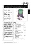
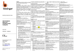
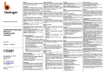
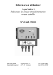
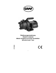
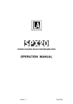
User Manual
Digital Water Level Indicator
for rain water storage tanks
We congratulate you on the purchase of Digital Water Level measuring device. You have purchased a high-quality product built to the highest standards of modern technology. Before you
start to assemble or operate the equipment, please read the user manual with care and verify
the parts supply for completeness.
List of parts supplied:
1. The Digital Water Level Indicator.
2. The stainless steel measurement probe (red and white connection cables approx.
10 feet long).
3. The Measurement Sensor Box.
4. Installation material, a spare fuse and spacers.
Important notes on safety:
Please, read and follow safety instructions carefully before assembly or using the device!
Equipment using a 120V AC supply may only be installed and commissioned by a qualified
tradesman. The assembly place must allow all possible safety precautions when laying the attached cables. Power supply cables and data cables may not be damaged or squeezed for any
reasons. Plan the assembly place so that you can reach the transformer easily and unplug it
from the electrical outlet in dangerous situations. Choose the assembly place so that children
cannot play or be near the device or its connections without supervision.
Before opening the device disconnect it from the main supply (unplug) otherwise there is a
serious danger of an electrical shock.
Fuses may only be replaced with standard-compliant parts with the same nominal value. All
liability is excluded for damages which result from non-compliance of these instructions or
from improper handling of the device.
At chosen intervals in this hand book we will give directions for safety precautions. These
safety precautions have been specially marked.
Otto Graf GmbH
Kunststofferzeugnisse
Carl- Zeiss Str. 2-6
D 79 331 Teningen
1
Tel.: 07641 5890
Fax: 07641 58950
1. Description of the equipment
The Digital Level Indicator has been developed especially for rain water usage. Synthetic
material
tanks are used. Cement and metal tanks are only conditionally usable. With the calibration
function the system is coordinated to the different tank heights. The fill level in the tank is
shown in 1% steps by a 3-digit LCD-display. The sensor electronics work with 12 volts of low
current and is reverse polarity protected; it is attached to the main device with a 65 foot data
cable. As soon as the calibration and the assembly are completed no further setting up is
necessary. The reference value for a 100% fill level remains stored in the case of a power
failure.
Performance features:
- Fill level indication in 1% steps
- Status LED which shows the operation in progress
- Self calibrating routine
- Permanent supervision of sensor electronics
- Error code message display
The following picture shows your newly acquired device:
1: Fastening holes
2: LCD- Display
3: Button for setting the max. filling
level
4: LED- On
Figure 1: Overall equipment list
2
Technical data:
Digital Water Level Indicator
Operating voltage
: 24V/60Hz
Power consumption : 3 watts
Output voltage
: 12 volts
Tank depth
: 10 feet
Sensor electronics
Measuring current : 12 volts =
Measuring frequency : 200 Hz-20 kHz
Data cable length
: 165 feet maximum
Measurements (LxWxD):
4.75”x3.1”x2.3” with protection : IP54
Measurements (LxWxD):
3.6”x3.2”x2” with protection : IP54
Fuse in the device
: T 50mA
2 . Assembly
2.1 Digital Water Level Indicator housing installation
Power must be disconnected during installation and service.
For the connection to the 120V line please use a plug-in transformer. Should it necessary to
open the housing, take care that the device has been disconnected from the main power supply
(unplugged). Mark out the hole positions on the wall and drill accordingly. After having fixed
the housing using the supplied screws and plugs, attach the data cables and the 24V AC output
of the plug-in transformer to the terminal block.
The device fuses are found inside the cover . Before changing the fuse it is important to disconnect the device from the main power supply (pull out the plug)! Loosen the four screws
holding the cover and lift carefully open. Replace the faulty fuse with the same rated (T50mA)
and recluse the cover. Refasten the cover with the four screws.
Figure 2: Position of the fuse
3
2 .2 Sensors and data cable connection:
The sensor electronics comprise of a stainless steel probe [22] with a red and a white connecting cable [27] and the sensor control box [28].
Figure 3: Sensor technology
1.
Now the sensor control box [28] (cover removed) should be installed on the tank
wall (preferably in the man hole shaft of the Graf synthetic tank). The location of
the mounted sensor control box should be at least 6 inches above the overflow [25].
The enclosed screws should be used to secure the device. After fully tightening the
screws, the points that are showing themselves on the outside of the tank must be
blunted to avoid injury [24].
2. Measure the height from the bottom of the tank [23] to the end of the terminals
[15] and [16] on the sensor control box [28].
3. Shorten the connection cable to suit the measured height.
4. After shortening the cable, the distance between the cable fastening spacers [21]
should be set equally along the entire length. The cable fastening spacers prevent
the red and white cables of the sensor from crossing over and thereby causing a
slight distortion of the measurement readings. If for any reason the cable fastening
spacers cannot be mounted, an additional distortion of the measurement reading of
approximately 1% may result.
5. Connect the sensor cable to the sensor as described in the following instructions:
Remove approximately 1/4” of the insulation from both of the wires. Next, pass
the red wire through the screw mounting 1 [19] and tighten this lightly, then
connect the red wire to the terminal [16]. The free white wire is now passed
through the screw mounting 2 [18] and tightened lightly, then connect the white
wire to the terminal [15].
6. Now pass the end of the data cable [12] through the screw mounting 3 [13]. Lightly
tighten the screw mounting and connect the cable wire cores of the data cable [12]
to the double terminal [14]. The connection of the data cable is reverse polarity
protected. Attention! The screws should be tightened with care to ensure that
they are not damaged through over tightening.
7.
Now recheck that all the screwed items and the sensor components have been fitted
4
correctly. Replace the cover of the sensor control box and secure this with the
appropriate fastening screws.
Note:
The red and the white wires going down to the probe should be straight and smooth to be
drawn taught by the weight of the stainless steel probe. The stainless steel probe must hang
just above the tank floor. When setting the spacers please be sure to distribute them equally
over the complete length as shown in Figure 4.
The following illustration clarifies the context:
5
12:
13:
14:
15:
16:
17:
18:
19:
20:
21:
22:
23:
24:
25:
26:
27:
28:
Data cable
screw cap 3
Connection of the data cable is reverse protected.
connect white wire here
connect red wire here
data cable terminal
screw cap 2
screw cap 1
active measuring length
When assembling be sure, that the cable spacers are equally distributed over the cable length.
Stainless steel probe
Tank floor
Screws must be blunted ! (danger of injury)
overflow
Tank side in dome
Sensor
Sensor control box
Figure 4: Sensor assembly
3. Activation and calibration process
Before energizing the equipment, check and be sure that all electrical connections are correctly
insulated and all covers are properly closed!
Now plug the plug-in transformer into the mains socket particular to the equipment. The green
LED "Power" must light up. The LCD display will run through range of number combinations
shown. These are used in the initialization of the equipment. The initialization is
completed as soon as the value stops and stays still, i.e. the display shows no further fluctuation.
The device now runs with the factory standard settings (measuring cable length of 6.5 feet).
Should you have a different measuring cable length then the device must be calibrated. To do
this proceed as follows:
6
Calibration procedure:
1. Fill the tank up to the maximum height.
If this is not possible then you should proceed with the alternative as follows:
- Fill a bucket with water.
- Put in the stainless steel probe with the red and white wires attached
in the required measuring lengths completely submersed in the water
then continue as from point 2.
2. Press the calibration button. The code "901" is shown in the LCD display.
3. Release the calibration button and wait until the code "902" is shown in the LCD
display.
4. Now press the calibration button again, quickly, to save the determined value. The
code "903" is shown briefly in the LCD display.
5. After this wait for a few moments until the display shows 100%.
Remark:
After the code "902" appears the calibration button must be immediately pressed, if this is
not done then the value will not be saved. If this happens then wait a moment and repeat the
process.
After the completion of the calibration, the fill level indicator is shown in %, in this case 100%
shows. (Slight variations may be caused by disturbance of the waters surface).
Note:
It is possible to re-set the fill level indicator to the factory settings at any time. To do this,
pull the plug-in transformer from the mains and wait for a few seconds. After this press the
calibration button and hold it pressed and re-plug the plug-in transformer into the power
outlet. Hold the button pressed until the LCD code "601" is shown in the display.
4. Error messages and fault elimination
Directly following switching on and during the operation mode the digital fill level indicator
checks the complete system equipment. If an error is diagnosed it will be shown on the LCD
display.
7
The following messages are possible:
602
The calibration process has not been carried out correctly.
This error code 602 occurs when the calibration button has been held too long. In this case
repeat the calibration process.
701
Sensor error (the sensor control box sends no signal)
Start with a check of all the connections of the
data cable in the display device and on the sensor
control box.
Control also for faulty cables (check for current)
Check also the terminals of the sensor control box
electrodes.
If all the cables have been correctly attached and there are no short circuits then the digital fill
level indicator must function properly. When the "701" code is still in the display then remove
the sensor completely from the tank (the sensor control box remains attached)
Attention: make sure the cover of the digital display device is in place and secured with 4
screws. Now reconnect the mains current!
The device must now show a value of 0 %. If this is not the case then the sensor is not
functioning properly.
Should the green LED not light up then the device show no function. Check once again all the
connections and of course the fuse. Don’t forget to also check the mains fuse. Should all attempts be without success please get in touch with a professional.
Purchase date
Device number
Tank height
: ................................................
: ................................................
: ................................................
Design and specifications are subject to change without notice
Dated: August 2011
8