1
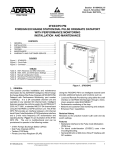
®
TM
SURVIVOR SST3
Direct Thermal Label Printer
Operation & Service
Manual
109181
Contents
About This Manual ................................................................................................................................... 1
1.0
Introduction.................................................................................................................................. 1
1.1 General Setup . . . . . . . . . . . . . . . . . . . . . . . . . . . . . . . . . . . . . . . . . . . . . . . . . . . . . . . . . . . . . . . . . . 2
1.1.1
1.1.2
1.1.3
1.1.4
1.1.5
Connecting the Interface Cable . . . . . . . . . . . . . . . . . . . . . . . . . . . . . . . . . . . . . . . . . . . . . . . . . . . . . . . 2
Split Communications Cable Installation . . . . . . . . . . . . . . . . . . . . . . . . . . . . . . . . . . . . . . . . . . . . . . . . 3
Loading Labels into the Printer . . . . . . . . . . . . . . . . . . . . . . . . . . . . . . . . . . . . . . . . . . . . . . . . . . . . . . . 8
Label Peel and Present . . . . . . . . . . . . . . . . . . . . . . . . . . . . . . . . . . . . . . . . . . . . . . . . . . . . . . . . . . . . 13
Auto Sense Setup . . . . . . . . . . . . . . . . . . . . . . . . . . . . . . . . . . . . . . . . . . . . . . . . . . . . . . . . . . . . . . . . 15
1.2 Washdown Procedure . . . . . . . . . . . . . . . . . . . . . . . . . . . . . . . . . . . . . . . . . . . . . . . . . . . . . . . . . . . 16
2.0
General Maintenance ................................................................................................................ 17
2.1
2.2
2.3
2.4
3.0
17
17
17
18
Parts Replacement .................................................................................................................... 19
3.1
3.2
3.3
3.4
3.5
4.0
General Cleaning . . . . . . . . . . . . . . . . . . . . . . . . . . . . . . . . . . . . . . . . . . . . . . . . . . . . . . . . . . . . . . .
Cleaning the Printhead . . . . . . . . . . . . . . . . . . . . . . . . . . . . . . . . . . . . . . . . . . . . . . . . . . . . . . . . . . .
Cleaning the Platen Roller. . . . . . . . . . . . . . . . . . . . . . . . . . . . . . . . . . . . . . . . . . . . . . . . . . . . . . . . .
Cleaning the Peel Off Roller . . . . . . . . . . . . . . . . . . . . . . . . . . . . . . . . . . . . . . . . . . . . . . . . . . . . . . .
Printhead . . . . . . . . . . . . . . . . . . . . . . . . . . . . . . . . . . . . . . . . . . . . . . . . . . . . . . . . . . . . . . . . . . . . .
Mean Time to Repair (MTTR) . . . . . . . . . . . . . . . . . . . . . . . . . . . . . . . . . . . . . . . . . . . . . . . . . . . . . .
Printhead Replacement . . . . . . . . . . . . . . . . . . . . . . . . . . . . . . . . . . . . . . . . . . . . . . . . . . . . . . . . . .
CPU Board Replacement . . . . . . . . . . . . . . . . . . . . . . . . . . . . . . . . . . . . . . . . . . . . . . . . . . . . . . . . .
Replacement Parts . . . . . . . . . . . . . . . . . . . . . . . . . . . . . . . . . . . . . . . . . . . . . . . . . . . . . . . . . . . . . .
19
19
19
21
22
Communications ........................................................................................................................ 23
4.1 Parallel Port . . . . . . . . . . . . . . . . . . . . . . . . . . . . . . . . . . . . . . . . . . . . . . . . . . . . . . . . . . . . . . . . . . . 23
4.2 Serial Port . . . . . . . . . . . . . . . . . . . . . . . . . . . . . . . . . . . . . . . . . . . . . . . . . . . . . . . . . . . . . . . . . . . . 23
4.2.1
Setting up the Baud Rate . . . . . . . . . . . . . . . . . . . . . . . . . . . . . . . . . . . . . . . . . . . . . . . . . . . . . . . . . . 24
4.3 USB . . . . . . . . . . . . . . . . . . . . . . . . . . . . . . . . . . . . . . . . . . . . . . . . . . . . . . . . . . . . . . . . . . . . . . . . . 24
4.4 Communicating to RLWS Indicators . . . . . . . . . . . . . . . . . . . . . . . . . . . . . . . . . . . . . . . . . . . . . . . . . 24
4.5 Printer Operation . . . . . . . . . . . . . . . . . . . . . . . . . . . . . . . . . . . . . . . . . . . . . . . . . . . . . . . . . . . . . . . 24
4.5.1
4.5.2
4.5.3
5.0
Serial Strings . . . . . . . . . . . . . . . . . . . . . . . . . . . . . . . . . . . . . . . . . . . . . . . . . . . . . . . . . . . . . . . . . . . . 25
Configuring Label Format in an RLWS Indicator. . . . . . . . . . . . . . . . . . . . . . . . . . . . . . . . . . . . . . . . . . 26
Gross Weight Label Format Example. . . . . . . . . . . . . . . . . . . . . . . . . . . . . . . . . . . . . . . . . . . . . . . . . . 26
Options ....................................................................................................................................... 27
5.1 Heater Kit Installation . . . . . . . . . . . . . . . . . . . . . . . . . . . . . . . . . . . . . . . . . . . . . . . . . . . . . . . . . . . . 27
5.1.1
Heater Fuse Replacement . . . . . . . . . . . . . . . . . . . . . . . . . . . . . . . . . . . . . . . . . . . . . . . . . . . . . . . . . . 34
5.1 Wireless Antenna Installation . . . . . . . . . . . . . . . . . . . . . . . . . . . . . . . . . . . . . . . . . . . . . . . . . . . . . . 34
6.0
Specifications ............................................................................................................................ 45
SURVIVOR® SST3TM Limited Warranty...................................................................................................... 46
Technical training seminars are available through Rice Lake Weighing Systems.
Course descriptions and dates can be viewed at www.ricelake.com or obtained
by calling 715-234-9171 and asking for the training department.
© 2010 Rice Lake Weighing Systems. All rights reserved. Printed in the United States of America.
Specifications subject to change without notice. January 2010
i
About This Manual
This manual is intended for use by technicians responsible for setting up and servicing the SURVIVOR® SST3TM
printer. Along with this manual, the Datamax® M ClassTM Mark II Operator’s Manual (RLWS PN 77562) is on a
CD-ROM and accompanies the SST3. It gives an overview of the operation, calibration, and in-depth
maintenance of the printer. (The Datamax manual can also be viewed or downloaded at the RLWS web site at
www.ricelake.com.)
The following service procedures are intended to instruct you on how to:
• Understand features and specifications of the SST3.
• Set up communications parameters.
• Perform general printer maintenance.
Warning
Great care should be taken when opening and closing the SST3 enclosure to ensure that fingers and
cables are not in the way of the enclosure cover.
Caution
Some procedures described in this manual require work inside the printer enclosure.
These procedures are to be performed by qualified service personnel only.
Authorized distributors and their employees can view or download this manual from the
Rice Lake Weighing Systems distributor web site at: www.ricelake.com.
1.0
Introduction
The SURVIVOR SST3 is a high-performance, high-speed direct thermal and optional thermal transfer industrial
washdown label printer.
Features include:
• Print speed of up to 10 inch per second (254 mm/sec).
• Common bar codes are resident in SST3 memory and can be printed with or without adjacent human
readable bar code interpretations.
• Character fonts can be printed in any one of four directions and with any one of nine different font sizes.
In addition, a resident smooth font, called CG Triumvirate, can be separately selected and contain 10
different font sizes. By using font multiplication, font size expands vertically and horizontally up to 24
times.
• Connects to most computers and controllers through either RS-232, USB or the Centronics parallel
interface.
• Optional Ethernet and/or wireless network communication.
• Software-selectable printhead temperature, print speed, slew rates and form dimensions provide the
option of storing a wide variety of parameters, thus eliminating the need for manual adjustments. This is
especially helpful when using several different types or brands of label stock, or when switching between
direct thermal and thermal transfer printing.
• Configurable for “one up” printing mode. With the present sensor installed and enabled, the next label is
not printed until the last label printed has been removed from the printer. Quantities of one-at-a-time can
be selected.
Introduction
1
1.1
General Setup
When setting up the SST3 printer, ensure that the unit is firmly placed on a sturdy, horizontal work surface that
has sufficient work space around the perimeter of the unit. The unit opens towards the front so adequate space
must be made available to allow the user to safely lift the cover of the unit and change out labels as needed.
Because the cover opens to the front, counter depth only needs to accommodate the base footprint of the unit.
The cover does not rest on counter top when open.
Front of unit
Warning
Unit should sit on a sturdy surface when the cover is open to prevent tipping. This could
cause injury to the user.
The unit comes with an eight foot power cord. Use appropriate GFI outlet types for the
appropriate environment.
The SST3 printer must be installed near an easily accessible power outlet to allow for quick
disconnect in case of emergency.
Warning
1.1.1
Since unit will be used around water, use appropriate grounded outlets (GFI). Not doing so
could cause injury to the user.
Connecting the Interface Cable
The SST3 can be interfaced to a host device via Ethernet, Parallel, Serial and USB ports. Use the appropriate
cable for your application (not included).
Ethernet Network Cable
Parallel Port Cable
USB Cable
Serial Port Cable
Figure 1-1. Various Types of Interface Cables
2
SST3 Installation Manual
Following power up, interface port selection occurs automatically upon detection of valid data. If the incoming
data flow stops and the host timeout period is achieved, partially received formats will be ignored and the port
detection process repeated.
Ethernet Connection
The Ethernet interface supports several menu-selectable modes. Depending on the length, the cable should be
Category/Type 3 or better. To order, ask for Rice Lake part number 103372. Installation documentation is
supplied with the interface option.
Parallel Connection
The parallel interface supports directional communications. Choose and connect cabling as follows:
• For uni-directional communication, use a Centronics IEEE 1284 cable with a 36-pin male connector; or
• For bi-directional communication, use an IEEE 1284 compliant cable with a 36-pin male connector (and
supporting host software).
USB Connection
The USB connection cable supports directional communications.
Serial Connection
The serial interface supports RS-232, RS-422, and RS-485 communications.
1.1.2
Split Communications Cable Installation
The SST3 printer enclosure comes with a unique cable installation assembly that ensures the interior of the unit
stays moisture free even during washdown conditions. The assembly allows the installer to eliminate the need to
cut cables and still maintain a watertight barrier. Use the following steps to install your cable of choice through
the split communications cable seal.
1. Using a 7/16” socket, remove the four nuts holding the split communications cable plate in place. Take
care in removing the nuts as they could slip and fall down between the plate and the printer enclosure.
Set the nuts aside.
Four nuts
Figure 1-2. Split Communications Cable Assembly in the SST3 Printer Enclosure
Introduction
3
2. Pull the SST3 enclosure forward so that it hangs slightly off of table edge to allow access to the bottom
access hole.
3. Remove split communications cable plates by pushing with fingers up through the bottom access hole
from the underside to dislodge the split communications cable plates. Set aside.
Figure 1-3. Remove the Component Parts of the Split Communications Cable Assembly
4. The split communications cable plate is made up of several individual pieces that are shown in Figure
1-4.
O-ring
Clamp plate
Split seal
plates
Half clamp
plate
Seal
plug
Split
communications
cable main plate
Large &
small split
seal
gromment
Figure 1-4. Component Pieces
5. Ensure the rubber gasket is seated properly in the SST3 printer enclosure.
Rubber gasket
Figure 1-5. Rubber Gasket
6. Set the main plate over the four studs with recesses around the four holes located downward and press
down.
4
SST3 Installation Manual
Note: Ensure that the split communications cable main plate is oriented so that the tapered side is facing up
as shown in Figure 1-6. An easy way to tell if the main plate is oriented correctly is to note that the four holes
on the main plate have counter bores which should face down. Refer to Figure 1-6.
.
Ensure that
the larger side
of the tapered
pocket
is
facing
upwards when
placing it on
the four studs
Note counter
bore
Figure 1-6. Incorrect and Correct Orientation of Main Plate
7. Pass the communications cable through the printer base and main plate. Make sure that the cable end and
printer communications socket match correctly.
Figure 1-7. Communications Cable Comes Up Through Bottom of Hole
8. Push the entire SST3 enclosure unit back onto the table or other sturdy work surface.
9. Assemble the split seal plates back together with the cable in between (Figure 1-8, left image).
Note: Run finger across the split seal plates to ensure there is no dirt or oil on the surface prior to joining the two
surfaces together.
Note: Make sure the larger diameter hole side is facing upwards as you put the two pieces together.
Figure 1-8. Assemble The Split Seal Plates Together
Introduction
5
10. Place the O-ring over the cable end and into the groove around the split seal plates (Figure 1-8, right
image). This will hold the plates together and also offer a watertight barrier.
11. Connect the communications plug to the appropriate connection on the back of the printer.
Figure 1-9. Connect the Communications Cable to the Back of the Printer
12. Carefully push the whole split seal assembly down into the printer enclosure as shown below.
Figure 1-10. Seat the Split Seal Assembly
13. Wrap a split grommet around the cable with the small end of the grommet pointing downwards. Orient
the grommet split to a position that is 90 degrees to the split in the split seal insert and press the grommet
into the tapered hole in the split seal insert. At this time, position the cable to make a 90 degree bend
from the printer.
Figure 1-11. Insert Split Grommet Onto the Split Seal Plates
6
SST3 Installation Manual
14. Place the half clamp plate onto the studs, then place the clamp plate onto the studs with the step facing
down and the half plate nesting in the step of the clamp plate.
Half clamp plate
Clamp plate - note
the step for the
half plate
Figure 1-12. Place Half Clamp Down on Assembly
15. Press the assembly down and partially tighten the four nuts that hold the entire assembly in place. Once
all the nuts are started, tighten the nuts in a diagonal sequence until all the nuts are tight using a 7/16”
socket and torque wrench. Tighten to 30 in/lb torque.
Warning: Over tightening can break the studs from the base.
Figure 1-13. Tighten Up The Entire Assembly
Figure 1-14. 7/16” Socket and Torque Wrench Used to Tighten Assembly in Figure 1-13
Introduction
7
1.1.3
Loading Labels into the Printer
Use the following steps to load labels into the printer.
1. Make sure printer is sitting on a horizontal surface.
2. Open printer cover by unlocking the hinged latches that are located on both sides of the unit and lifting
the cover to the front of the unit.
Open the
hinged
latches
Figure 1-15. Hinged Latch Location
3. Open the media cover and lower the media hanger guide (if equipped) and media guide
4. Press in on the printhead latch and raise the printhead assembly.
1. Printhead Latch
2. Media Guide
3. Media Hanger Guide
Figure 1-16. Printhead Loading Sequence
5. Slide the roll media onto the media hub or media hanger. If the printer is equipped with a media hanger,
raise the media hanger guide. The media hanger guide should be pushed inward so that it is just touching
the roll media.
8
SST3 Installation Manual
6. Route the media through the printer as shown. Raise the media guide. The media guide should be pushed
inward so that it is just touching the edge of the media.
1. Roll Media
2. Media Hanger Guide
3. Media Sensor
4. Media Guide
Figure 1-17. Routing Media Through Printer
7. Close the printhead assembly and press down until it locks into place.
8. Close the cover and press the FEED button several times to position the media and ensure proper
tracking. If the printer does not correctly sense the top of each label, it may be necessary to calibrate the
printer.
1. Printhead Assembly
Figure 1-18. Printhead Assembly
Introduction
9
Loading Optional Ribbon into the Printer
1. Make sure printer is sitting on a horizontal surface.
2. Open printer cover by unlocking the hinged latches that are located on both sides of the unit and lifting
the cover to the front of the unit.
3. Press in on the printhead latch and raise the printhead assembly.
1. Printhead Latch
Figure 1-19. Open Printhead Latch to Load Optional Ribbon
4. Wrap the ribbon around the ribbon hub and rotate the ribbon take up shaft several times to take up all the
slack and remove any wrinkles in the ribbon.
Ink Side (CSO
ribbon)
Figure 1-20. Wrap Ribbon Around Ribbon Spool
10
SST3 Installation Manual
Ink Side (CSI ribbon)
1. Ribbon Roll
2. Ribbon Supply Hub
3. Ribbon Idler
Figure 1-21. Feed Ribbon Through Printer
1. Printhead Assembly
Figure 1-22. Close Printhead Assembly
1. Printhead Assembly
Figure 1-23. Latch Printhead Assembly
Introduction
11
1. Ribbon Take-up Hub
Figure 1-24. Ribbon Take-up Hub Diagram
12
SST3 Installation Manual
1.1.4
Label Peel and Present
Use the following steps to load label peel and present. With this option, labels printed in a batch will
automatically be separated from the backing material and dispensed on demand which means printing will occur
only after a previously printed label has been removed from the printer.
1. Make sure printer is sitting on a horizontal surface.
2. Open printer cover by unlocking the hinged latches that are located on both sides of the unit and lifting
the cover to the front of the unit.
3. Press in the latch to open the mechanism as shown in Figure 1-25.
Press latch mechanism
to open.
Figure 1-25. Opening Latch for Peel and Present
4. Swing the mechanism open as shown in Figure 1-25.
5. Load the printer with media.
Figure 1-26. Load Printer With Media
6. Load the media into the printer as you normally would for tear-off operation, however, extend an
additional 12 inches (30 cm) of media out the front of the printer.
7. From this above 12 inches of media, remove all of the labels, so that only the backing material remains.
Introduction
13
8. Route the backing material under the assist roller and around the internal rewinder as shown below.
Figure 1-27. Route Backing Material Under Assist Roller
9. Put the leading edge of the backing material into a slot on the internal rewinder and insert the media clip.
Be sure the leading edge of the backing material is cut square and that is inserted evenly into the slot.
Figure 1-28. Place Backing Material onto Internal Rewinder
10. Manually rotate the internal rewinder to remove slack from the backing material.
Figure 1-29. Flip Mechanisms Back Down to Secure Labels
11. Flip the holding mechanisms down to secure the labels as shown in Figure 1-29.
12. Plug in and turn “on” the printer. After initialization, press the FEED button to align the next label to the
top of form position. (If a peeled label is presented, remove it to proceed). The printer is now ready for
on-demand use.
14
SST3 Installation Manual
1.1.5
Auto Sense Setup
The present sensor is automatically set up when installed. If necessary to set up at a later time, use the following
steps to set up the auto sense.
1. Access the menu through the front panel of the printer.
Time and Date
Printer Status Line
Current State Icons
Fault
Paused/Stopped
Receiving Data
Main Display Area
Soft Key Labels
Soft Keys
Menu, Test and Navigation Buttons
Figure 1-30. SST3 Main Display
2.
3.
4.
5.
Press through the menu on the front panel until you get to Printer Options.
Press the down or up key to access Present Sensor.
Enable the sensor.
Press the Enter key to save and exit.
Introduction
15
1.2
Washdown Procedure
Warning The following instructions must be followed explicitly. Failure to follow these
instructions will result in damage to the contents inside enclosure and/or create a hazardous
condition.
This section describes the general procedure for washdown applications.
1. Unplug power to the printer.
2. Securely latch the main latches on the side of the enclosure.
Main latches (one on
each side of enclosure)
Figure 1-31. Secure Main Latches
3. Ensure that the label presentation chute cover is securely closed. The label cover tab will be tightened
securely against retaining washer and mounting block.
Mounting block
Presentation chute cover
Figure 1-32. Presentation Chute Location
4. Perform washdown.
5. Dry the outside of the enclosure thoroughly before opening.
6. Open the label presentation chute cover (Figure 1-32) first to relieve any pressure or vacuum that might
be present.
7. Plug the printer back in after the washdown procedure is completed making sure that the power plug is
completely dry after washdown before inserting into a GFI rated outlet.
16
SST3 Installation Manual
2.0
General Maintenance
This section describes procedures for general maintenance and cleaning of the SST3 printer.
2.1
General Cleaning
During normal operation, media debris may accumulate around the printer mechanism inside the printer. This
debris should be removed regularly using a soft bristle brush and/or vacuum cleaner.
2.2
Cleaning the Printhead
Foreign particles can collect on the printhead, causing characters or bar codes to appear light or faded. This type
of problem is evidenced by a continuous light streak which appears in the same physical position on each printed
line. This condition should only appear after extensive printer operation or if poor quality paper has been used. It
is recommended that Rice Lake Weighing Systems-supplied labels are used to obtain continuous high quality
printing.
Recommended printhead cleaning intervals:
• Due to abrasion and foreign particle deposits, direct thermal printheads should be cleaned every 50,000
linear inches (approximately eight rolls of labels) (12700m).
• Thermal transfer printheads should be cleaned at least every 250,000 linear inches (approximately 40
rolls of labels).
Printhead cleaning procedure:
1. Unplug printer from the outlet.
2. Open cover. Unlock and raise printhead.
3. Gently wipe underside of printhead burn-line area using a cotton swab moistened (not soaked) with
isopropyl alcohol. Allow to dry.
4. Lower and lock printhead.
5. Close cover. Plug in and turn on printer.
2.3
Cleaning the Platen Roller
Use the following steps to clean the platen roller of the SST3.
1. Turn off and unplug the printer from outlet.
2. Open the cover. Rotate the platen roller.
Platen Roller location
Figure 2-1. Platen Roller Location
General Maintenance
17
3. Use a clean cotton swab or a lint-free cloth dampened with isopropyl alcohol to wipe off all debris from
the platen roller. Manually rotate the roller to clean the entire surface. Allow to dry.
4. Lower the printhead assembly and lock into position.
5. Close the cover. Plug in and turn on the printer.
2.4
Cleaning the Peel Off Roller
Use the following steps to clean the peel off the roller.
1. Turn off and unplug the printer from the outlet.
2. Rotate the peel off roller.
3. Use a clean cotton swab or a lint-free cloth dampened with isopropyl alcohol to wipe off all debris from
the peel off roller.
18
SST3 Installation Manual
3.0
Parts Replacement
The following sections outline part replacement guidelines and procedures, and list replacement parts for the
SURVIVOR SST3 printer
3.1
Printhead
The SST3 uses a thin film printhead that dissipates heat faster than thick film, providing a longer head life.
Printhead warranty is 1,000,000 linear inches (when used with direct thermal labels or 2,000,000 inches in the
thermal transfer mode (with ribbons).
3.2
Mean Time to Repair (MTTR)
Estimated MTTR the printer is less than 15 minutes. A number of factors contribute to the ease of service.
Primarily, all electronics including the power supply are located on a single plug-in circuit board. Most electronic
problems can be isolated and repaired with a simple board swap.
The printhead is also designed for easy replacement. One mounting screw and two locator pins eliminate the
mechanical head adjustments required of other thermal label printers.
3.3
Printhead Replacement
1. Printhead Mounting Screw
Figure 3-1. Printhead Replacement
Removal:
1. Touch a bare metal part of the printer frame to dissipate any static electricity that may be present.
2. Turn the printer off and unplug from the outlet. Open the media cover.
3. With the printhead locked in the down position, loosen the printhead mounting screw (location shown in
Parts Replacement
19
Figure 3-1). Carefully unlatch the printhead assembly and disconnect the two cables from the printhead.
Figure 3-2. Remove Old Printhead Assembly
Replacement:
1. Reconnect the printhead cables.
2. Position the printhead on the printhead assembly and tighten the printhead mounting screw (do not
overtighten).
3. Clean the printhead.
4. Reload ribbon (if removed), lower the printhead assembly, and rotate the printhead latch back into
locked position.
Caution
20
Be sure to ground yourself to the chassis before you remove or install the printhead. This
prevents a static discharge from your body through the printhead to the ground.
SST3 Installation Manual
3.4
CPU Board Replacement
Removal:
1.
2.
3.
4.
Touch a bare metal part of the printer frame to dissipate any static electricity that may be present.
Turn the printer off and unplug from the outlet.
Unlatch the SST3 hinges.
Remove screws from the printer enclosure (6 total).
Figure 3-3. Remove Screws from Enclosure
5. Remove the metal cover which houses the CPU board.
6. Unplug all ribbon cables that connect to the CPU board. There are seven different connections and each
one is labeled corresponding to the position on the board.
7. Unscrew the front panel screws and slide the CPU board out.
Figure 3-4. Remove Front Panel Screws
Replacement:
1. Slide new CPU board into the enclosure.
2. Use screws to attach board to enclosure.
3. Reconnect all ribbon cables and connectors. All connector and cables are marked to corresponding board
placement.
4. Replace the metal cover which houses the CPU board and replace the screws.
Parts Replacement
21
3.5
Replacement Parts
Part Number
Description
164976
Board, Main 8 MB flash
53936
Gear, spur 24t
53923
Idler post
104972
Power supply board
103369
Printhead, 203 dpi
107162
Upper platen roller kit
108880
Display
108717
Gasket, label presentation
108891
Printer, M-4210
108894
Gasket, latch mount
109431
3/1.5 inch media supply hub
109432
Stepper motor
108868
Display cover
109636
Ribbon cable 26 inches
88733
Breather Vent
Table 3-1. Replacement Parts
22
SST3 Installation Manual
4.0
Communications
Using a data detection process, the interface selection occurs automatically in the printer. At power-up, the
printer begins monitoring the interface ports for activity. When the host transmits data, the printer port detecting
this data is set active and remains active as long as data flow continues. Once the incoming (received) data flow
stops and the host timeout value is exceeded, the detection process is repeated. Should the data flow stop before
a complete label format is received, the format is ignored and must be sent to the printer again.
Note: To change an active port immediately, cycle the printer power off and on.
4.1
Parallel Port
The parallel interface has two menu-selectable modes of operation: uni-directional or bi-directional. The
uni-directional mode supports forward channel only communication and requires Centronics® cable with a 36-pin
male connector.
The bi-directional mode supports forward and reverse channel IEEE 1284 Compliant communications. Data can
be returned to the host in this mode provided it has compliant hardware, supporting software and is connected to
the printer via an IEEE 1284 Compliant cable with a Centronics 36 pin male connector.
4.2
Serial Port
The serial interface supports RS-232C and, if equipped, RS-422 communications. The following list of serial
port settings is menu-selectable and must match the host computer’s serial port settings.
• Baud rate (serial communication speed)
• Word length
• Word parity
• Number of stop bits
• Handshaking protocol
In addition to the port settings, the serial interface cable wiring must have specific connections (pin-outs) for
proper data exchange between the host and printer. The different serial cable pin-outs and suggested applications
are shown in Figure 4-1.
PC (DB-9S) to Printer
HOST DB-9S
PRINTER DB-9P
PC (DB-25S)
to Printer
HOST DB-25S
PRINTER DB-9
TX 3
RX 2
2 RX
3 TX
7 RTS
TX 2
RX 3
2 RX
3 TX
7 RTS
CTS 8
4 DTR
CTS 5
4 DTR
DSR 6
GND 5
8 CTS
GND 5
DTR 4
SHIELD
DSR 6
GND 7
8 CTS
GND 5
DTR 20
SHIELD
SHIELD
SHIELD
Figure 4-1. Serial Interface Cable Pin outs
Communications
23
4.2.1
Setting up the Baud Rate
Use the following steps to set up the baud rate on the printer.
1. Push the Menu key to access the communications menu.
2. Use the Up and Down keys to access the baud rate, parity, data bits and stop bits. The default settings are
9600, 8, and none.
3. Save and exit out of the menu.
4.3
USB
The USB connection supports Windows 95 and greater operating systems with a USB connection.
Optional - Ethernet print servers (wired and wireless) are available.
4.4
Communicating to RLWS Indicators
To communicate from a RLWS indicator directly to the SST3, a change to the standard RS-232 output is
required. The indicator must have Smart Serial communication or a custom serial format developed.
Minimum cable requirements are ground plus TX with the ground going to pin 5 on the printer and TX going to
pin 2 on the printer.
4.5
Printer Operation
The SST3 uses a Datamax M-Series Mark II printer. Complete operation information is enclosed on the CD that
accompanies this product. Specific information relating to operation, main menu structure, setting up parameters
are contained in the CD
.
24
SST3 Installation Manual
4.5.1
Serial Strings
To develop the correct serial string, you first need to understand the Datamax® Programming Language (DPL)
serial string. For every piece of information printed, the print format record must consist of the following three
pieces of information:
• A header that is fifteen characters long. The header specifies which font is used and where the data is
printed.
• Data to print.
• Termination character (such as a carriage return).
Header
A typical DPL serial string header consists of the following pieces of information:
Data
STX
Definition
Description
Start of text
Must have start of text at beginning of character stream
Label
Designation of label
Character rotation
Rotation of characters
_
Font
Font choice
_
Horizontal rotation
Horizontal (width) muliplier
_
Vertical rotation
Vertical (height) multiplier
000
Bar code
Dependant on type of bar code selected
• If printing graphics, lines, boxes, and human-readable fonts 0 through 8,
these three characters are ignored, but they still must be sent to the printer as
000.
• For human-readable font 9, these three characters must be a number from
001 to 010 to select a font size for the CG triumvirate smooth font. Other
selections are available if downloading from RAM, flash memory modules,
ROM font modules.
• For bar code fonts, these three characters represent a bar code height
number. Numbers ranging from 001 (or 0.01 inch) to 999 (or 9.99 inches).
1250
Row address
Four characters are the vertical offset in hundredths of an inch
0200
Column
Four characters are the horizontal offset in hundredths of an inch
L
1–4
Table 4-1. Serial String Header
Data String, Carriage Return and Execute Command
After the header, a data string and a carriage return are needed for each item to be printed.
Data
TEXT
CR
E
Definition
Description
Printed information (data
string)
Data to be printed (limited by range of printhead). Data string is terminated by a
carriage return
Carriage return
Carriage return terminates data string
Execute
At end of label data information, execute signals the end of the label to the printer
Table 4-2. Data String, Carriage Return and Execute Command
Communications
25
4.5.2
Configuring Label Format in an RLWS Indicator
Use the following steps to configure label format in an RLWS indicator:
1. Determine the operation mode in which you are printing. This step is important to make sure the correct
format is stored in gross, net or other format modes available in the indicator.
2. Create the format.
4.5.3
Gross Weight Label Format Example
The following is a format string example for a gross weight label configured in an RLWS indicator.
2 76 60 78 76 62 49 51 49 49 48 48 48 48 49 48 48 48 48 53 48 60 71 62 60 78 76 62 69
STX L < N L > 1 3 1 1 0 0 0 0 1 0 0 0 0 5 0 < G > < N L > E
Key In
Data Stream
Figure 4-2. Simple Gross Weight Data Stream/ASCII Example
10000 LB
Figure 4-3. Simple Gross Weight Label Example
Sample download label is available at www.ricelake.com/supports downloads/printers/label templates.
26
SST3 Installation Manual
5.0
Options
The following option is available with the SST3 printer.
• SST3 Printer Heater Kit, PN 111121
• SST3 Wireless Antenna Kit, PN 114543
5.1
Heater Kit Installation
Warning
Installation of the optional heater kit requires work inside the printer enclosure. This procedure is to
be performed by qualified service personnel only.
Figure 5-1. SST3 Printer Heater Kit
The Hoffman heater is designed to protect labels, sensitive mechanical, electrical and electronic equipment from
the harmful effects of condensation, corrosion from condensation, and low temperatures. Thermostatically
controlled, the fan-driven heater maintains a stable temperature within the enclosure to allow component parts to
perform reliably over a longer period of time.
Whether installing the heater for the first time or replacing the unit, there are several steps involved with the
installation.
The heater kit should be mounted to the enclosure panel using existing studs in the area indicated in Figure 5-2.
Heater Location within
the SST3 printer
enclosure
See Figure 5-5 for the second
mounting stud location
This stud is shared with the cover
Figure 5-2. Hoffman Heater Location
Options
27
The heater kit comes with the following parts.
Hoffman heater, fuse,
mounting bracket and
wire harness
Nut (qty. 1)
Figure 5-3. SST3 Printer Heater Kit Component Parts.
Use the following steps and photos to install or replace the heater.
1. Unplug power to the unit.
2. Disconnect any cables such as the power cord and the communications cable located on the back of the
printer, and the ribbon cable located at the front of the printer.
Power cord
Figure 5-4. Disconnect Power and Printer Cables
28
SST3 Installation Manual
3. Using a 3/8” socket, carefully remove the four nuts that are holding the printer pad to the printer base
plate in the SST3 enclosure and set nuts aside.
Remove the nut
from the power cord
cover and set aside.
Use 3/8” socket to remove
four nuts on printer pad
Second heater mounting
stud
Figure 5-5. Unscrew Four Nuts Holding Printer Pad to Printer Base Plate
4. Gently pull the printer and printer pad off the printer base plate mounting studs and set aside. The printer
base plate is now exposed.
Figure 5-6. Pull Printer and Mounting Pad Off Base Plate
5. Remove the upper nut on the power cord cover.
Remove nut and set
aside
Figure 5-7. Remove Upper Nut of the Power Cord Cover Assembly
Options
29
6. Remove the terminal strip nuts that are holding down the clear terminal strip cover using a 5/16” socket.
Set the clear plastic terminal strip cover aside and ensure that the plastic spacers do not get lost (shown in
Figure 5-9).
Figure 5-8. Terminal Strip Location, Wiring, and Clear Cover
7. Using a phillips head screwdriver, remove the three open terminal screws located on the terminal block.
Plastic spacers x 2
Figure 5-9. Remove Open Terminal Screws
30
SST3 Installation Manual
8. Set the heater into position onto the two threaded posts and using a 3/8” socket, tighten up the nuts to
secure the heater to the enclosure base.
Note: The heater kit comes with one nut as shown in Figure 5-3. Use the second nut which comes from the upper left
hand corner to secure the heater.
Sec on d n ut not
shown in left hand
photo
Figure 5-10. Secure Heater to Enclosure Bottom
9. Take the wire harness and match up the colors on the terminal strip block and the wire harness.
Figure 5-11. Color Match Wire Harness and Terminal Strip Wires
10. Connect the wire harness to the terminal strip block as shown.
BLK/ BROWN
WIRE
WHITE/BLUE
WIRE
GREEN
GROUND
Figure 5-12. Connect Wiring Harness to Terminal Strip
Options
31
11. Making sure the plastic spacers are in place, put the clear plastic terminal strip cover on top of the
terminal strip and using just the 5/16” socket, tighten the two nuts. This should be done by hand to snug
the nuts. Over tightening can crack the clear plastic cover.
Plastic spacers x 2
Figure 5-13. Replace Clear Plastic Cover and Gently Tighten
12. Gently peel off adhesive backing from the three square cable ties. The location of placement of the
square cable ties are noted on the bottom of the SST3 enclosure. Press the square cable ties firmly onto
the enclosure bottom where noted.
Remove backing paper
Template location for square adhesive cable ties
Figure 5-14. Secure Square Adhesive Cable Ties to SST3 Enclosure Bottom
13. Set the printer unit back down onto the printer base plate, lining up the four metal studs. Also ensure the
ribbon cable at the front of the printer is also out of the way when placing the printer back into the
enclosure. Note the ground wire location leading to the front of the SST3 enclosure. The wires should
run between the side of the SST3 enclosure and the metal standoff. By doing so, will eliminate the risk of
wires being pinched.
Figure 5-15. Don’t Pinch Ground Wire
32
SST3 Installation Manual
14. Secure the printer pad to the enclosure bottom by securing four nuts and tightening using a 3/8” socket.
Figure 5-16. Secure All Four Nuts Holding Printer Pad to Enclosure Bottom
15. Re-attach the ribbon cable located at the front of the unit.
Place ribbon
cable under
clamp
Figure 5-17. Re-Attach Ribbon Cable
16. Re-attach any other cables.
Options
33
5.1.1
Heater Fuse Replacement
The Hoffman heater has a fuse that could possibly need replacing. Use the following steps to replace the fuse.
1. Using a slotted screwdriver, push against the fuse holder cover and turn at the same time. This will
dislodge the fuse from the receptacle.
Fuse location on heater
Push and turn to remove fuse
Figure 5-18. Push and Turn Fuse Receptacle to Remove
2. Pull the actual fuse from the receptacle and replace with a new fuse.
Figure 5-19. Remove Actual Fuse From the Receptacle and Replace with a New Fuse
3. Reverse the removal steps to re-install the fuse holder cover.
5.2
Wireless Antenna Kit
Use the following procedure to install the wireless antenna option on the SST3 Printer.
This kit contains the following items:
• Communication Card (PN 103373)
• Antenna
• Ribbon Cable
• Standoffs
The following list of tools is required to install the wireless antenna option:
• #2 Phillips head screwdriver
• 7/16" Socket
• 9/32" Socket
34
SST3 Installation Manual
5.2.1
1.
2.
3.
4.
5.
Prepare the Printer
Touch a bare metal part of the printer frame to dissipate any static electricity that may be present.
Turn the printer off and unplug from the outlet.
Unlatch the SST3 hinges.
Remove screws from the printer enclosure (6 total)
Remove the metal cover which houses the CPU board.
Figure 5-20. Remove Screws from Enclosure
6. Remove the two screws and the cover plate from the rear of the printer using a #2 Phillips head
screwdriver or a 9/32” socket.
Figure 5-21. Remove Screws from Cover Plate
Options
35
5.2.2
Install the Communication Card
1. Insert the two supplied standoffs into the printer’s main board as shown using a gentle twisting motion
on standoff, being careful not to damage board during assembly.
With t-shaped
end out as
shown, insert the
two standoffs on
the main board
Figure 5-22. Insert Standoffs On Main Board
2. Slide the communication card into the rear of the printer. Align the two holes in the communication card
with the two previously installed standoffs.
Align card
to installed
standoffs
Figure 5-23. Align Communication Card to Installed Standoffs.
3. Press the communication card carefully onto each of the standoffs until standoff secures card in place.
4. Install the two previously removed cover plate screws.
36
SST3 Installation Manual
5. Install each end of the supplied ribbon cable into its corresponding connectors on the printer’s main
board and communication card. Use care to prevent damage to either board during cable assembly.
Figure 5-24. Install Ribbon Cable
6. Re-install the printer’s cover and associated screws.
5.2.3
Install the Antenna
1. Using a 7/16” socket, remove the four nuts holding the split communications cable plate in place. Take
care in removing the nuts as they could slip and fall down between the plate and the printer enclosure.
Set the nuts aside.
Four nuts
Figure 5-25. Split Communications Cable Assembly in the SST3 Printer Enclosure
2. Pull the SST3 enclosure forward so that it hangs slightly off of table edge to allow access to the bottom
access hole.
Options
37
3. Remove split communications cable plates by pushing with fingers up through the bottom access hole
from the underside to dislodge the split communications cable plates. Catch bolts if they fall through. Set
aside.
Figure 5-26. Remove the Component Parts of the Split Communications Cable Assembly
4. The split communications cable plate is made up of several individual pieces that are shown in Figure
5-27.
O-ring
Clamp plate
Split seal
plates
Half clamp
plate
Seal
plug
Split
communications
cable main plate
Large &
small split
seal
gromment
Figure 5-27. Component Pieces
5. Remove the four bolts from the printer case. These bolts can be saved or discarded.
Figure 5-28. Four Bolts Removed
38
SST3 Installation Manual
6. Loosen four screws on antenna assembly so the four bolts attached are loose and flexible yet attached to
the plate.
Bolts
Screws
Figure 5-29. Loosen Four Screws on Bottom of Antenna Assembly
7. Insert four loosened bolts on antenna kit through the printer base, along with cable through the opening
in the base.
Figure 5-30. Installing Antenna Kit Bolts and cable Through Printer Base
Options
39
8. Ensure the rubber gasket is seated properly around the bolts in the SST3 printer enclosure.
Figure 5-31. Press Down Rubber Gasket Around Bolts
9. Set the main plate over the four studs with recesses around the four holes located downward and press
down.
Note: Ensure that the split communications cable main plate is oriented so that the tapered side is facing up as shown in Figure
5-32, right image. An easy way to tell if the main plate is oriented correctly is to note that the four holes on the main plate have
counter bores which should face down. Refer to Figure 5-32.
Ensure that
the larger side
of the tapered
pocket
is
facing
upwards when
placing it on
the four studs
Note counter
bore
Figure 5-32. Incorrect and Correct Orientation of Main Plate
10. Push the entire SST3 enclosure unit back onto the table or other sturdy work surface.
40
SST3 Installation Manual
11. Assemble the split seal plates back together with the cable in between (Figure 5-33, left image).
Note: Run finger across the split seal plates to ensure there is no dirt or oil on the surface prior to joining the two surfaces
together.
Note: Make sure the larger diameter hole side is facing upwards as you put the two pieces together.
Figure 5-33. Assemble The Split Seal Plates Together
12. Place the O-ring over the cable end and into the groove around the split seal plates (Figure 5-33, right
image). This will hold the plates together and also offer a watertight barrier.
13. Connect the communications plug to the appropriate connection on the back of the printer.
Figure 5-34. Connect the Communications Cable to the Back of the Printer
14. Carefully push the whole split seal assembly down into the printer enclosure as shown below.
Figure 5-35. Seat the Split Seal Assembly
Options
41
15. Wrap a small hole grommet that is included with the printer around the cable with the small end of the
grommet pointing downwards. Orient the grommet split to a position that is 90 degrees to the split in the
split seal insert. (See Figure 5-36, left image) Press the grommet into the tapered hole in the split seal
insert. (See Figure 5-36, right image) At this time, position the cable as shown below. (See Figure 5-36,
bottom center image)
Make certain slack is
present as shown in
picture to allow
sealing of cable to
print case
Figure 5-36. Insert Split Grommet Onto the Split Seal Plates
16. Place the half clamp plate onto the studs, then place the clamp plate onto the studs with the step facing
down and the half plate nesting in the step of the clamp plate.
Half clamp plate
Clamp plate - note
t h e s t e p f or t h e
half plate
Figure 5-37. Place Half Clamp Down on Assembly
42
SST3 Installation Manual
17. Press the assembly down and partially tighten the four nuts that hold the entire assembly in place. Once
all the nuts are started, tighten the nuts in a diagonal sequence until all the nuts are tight using a 7/16”
socket and torque wrench. Tighten to 30 in/lb torque.
Figure 5-38. Tighten Up The Entire Assembly
When tightening plates make certain to allow enough slack in cable. See Figure 5-39.
Make certain slack is
present as shown in
picture to allow
sealing of cable to
print case
Figure 5-39. Keep Proper Amount of Slack in Cable
18. Close and latch printer cover.
19. Turn printer case on side to expose four mounting screws on bottom.
20. Tighten four screws with Phillips Screwdriver.
Four
mounting
screws
Figure 5-40. Tighten Four Mounting Screws
Options
43
21. Set printer on feet again.
W ireless
Antenna
Figure 5-41. Installed Wireless Antenna
22. Plug printer back in. Open cover and turn on power.
23. After printer display shows it is ready, configure printer and devices to communicate with each other per
the instructions provided by Datamax (DMXrfNetII and DMXNetII Card Option Operation Instructions,
Network Setup, Page 5.
44
SST3 Installation Manual
6.0
Specifications
Printing
Type
Print Speed
Resolution
Resident Fonts
Downloadable Fonts
Font Expansion
Bar Codes
RS-232C
Direct thermal or optional thermal
transfer
2" – 10" per second (51mm – 152mm)
in.5” programmable increments
203 dpi (8 dots/mm)
Ten alphanumeric fonts from 0.03" H –
0.25" H (0.9mm – 6.26mm) including
OCR-A, OCR-B (size and character
set III), and a CG Triumvirate smooth
font from AGFA
True-Type, AGFA Intellifont, Bitmap
All fonts expandable vertically and
horizontally up to 24x; fonts and
graphics can be printed in four
directions: 0º, 90º, 180º, and 270º
Code 3 of 9, UPC-A, UPC-E,
Interleaved 2 of 5, Code 128, EAN-8,
EAN-13, HIBC, Codabar, Plessey,
UPC 2 and 5 digit addendums, Code
93, Postnet, UCC/EAN Code 128,
Telepen, UPS MaxiCode, FIM,
PDF417, USD-8, Datamatrix, QR
Code, Aztec, TLC 39, Micro PDF417,
RSS
Media
Width
Length
Thickness
Type
Supply Roll Capacity
Media Supply
Media Sensing
Thermal Transfer
Ribbon
1.0" – 4.65" (25.4mm – 118mm)
0.25" – 99" (6.35mm – 2514.6mm) at
100 dots per inch
0.0025" –.010” (0.0635mm –
0.254mm)
Roll-fed or fan fold materials, die cut or
continuous labels; perforated or
continuous tag/ticket stock
8" (203mm) maximum outside
diameter on a 3" (76mm) core.
7" (178mm) maximum outside
diameter on a 1.5" (38mm) core.
Fanfold stock accepted from rear and
bottom of printer.
Solid metal hanger
“See through” for liner backed die cut
labels and tags. Reflective sensor for
black mark label media.
Black or colored inks; 360 meters
long, 4.6 microns, backcoated, ±10%
label width. 1968 feet (600 meters)
max
2400, 4800, 9600, 19.2K, 28,800, or
38.4K baud
USB
Wireless
Character Set
Word Length
Handshaking
ANSI ASCII character set.
Selectable 7 or 8 bit data format
XON/XOFF (on receive mode only) and
CTS/DTR
Input Buffer
Approximately 7000 bytes; XOFF is
transmitted and DTR goes low when
60 bytes are available in the buffer.
XON is transmitted and DTR goes high
when 1000 bytes are left in the buffer
Characters transmitted with no parity from the printer
Electrical
Input Voltage
103.5 - 126.5 or 207 - 253 VAC,
47 -63 Hz - Must use appropriate
heater and power cord for voltage
used
Note: The GFI socket outlet should be installed near the
equipment and be easily accessible
Heater Circuit Protection At 115V = 2.0A Fastact
230V = 1.0A Fastact
Grounding
Unit must be connected to a properly
grounded receptacle
Power Consumption 90 watts (standby - 10 watts)
UL Listed (pending)
Type 4X for indoor use only - NEMA
4X, IP66, IP69K
Memory Modules
Internal Memory
Module
PCB without fonts
FONT/FLASH modules
4 MB addressable
Font Modules
Font Modules
Range of Fonts
Eight available
ILPC, Kanji Simplified Chinese and I/O
Expansion Board
Environmental
Operating
Temperature
Humidity
Ventilation
Dust
Electromagnetic
Radiation
40°F – 95°F (4°C – 35°C)
10% – 95% non-condensing
Free air movement
Nonconducting, non-corrosive
Moderate RF fields can be tolerated
Mechanical
Switches
Switches
CANCEL, PAUSE, and FEED. Variable
Head Temperature Control
Size
Weight
27-1/8”L x 14” W x 13-5/8” H
Approximately (65-70 lbs)
Communications Interfacing
Parallel and IEEE
Specifications
45
SURVIVOR® SST3 Limited Warranty
Rice Lake Weighing Systems (RLWS) warrants that all RLWS equipment and systems properly installed by a
Distributor or Original Equipment Manufacturer (OEM) will operate per written specifications as confirmed by
the Distributor/OEM and accepted by RLWS. All systems and components are warranted against defects in
materials and workmanship for one year.
RLWS warrants that the equipment sold hereunder will conform to the current written specifications authorized
by RLWS. RLWS warrants the equipment against faulty workmanship and defective materials. If any equipment
fails to conform to these warranties, RLWS will, at its option, repair or replace such goods returned within the
warranty period subject to the following conditions:
• Upon discovery by Buyer of such nonconformity, RLWS will be given prompt written notice with a
detailed explanation of the alleged deficiencies.
• Individual electronic components returned to RLWS for warranty purposes must be packaged to prevent
electrostatic discharge (ESD) damage in shipment. Packaging requirements are listed in a publication,
Protecting Your Components From Static Damage in Shipment, available from RLWS Equipment Return
Department.
• Examination of such equipment by RLWS confirms that the nonconformity actually exists, and was not
caused by accident, misuse, neglect, alteration, improper installation, improper repair or improper
testing; RLWS shall be the sole judge of all alleged non-conformities.
• Such equipment has not been modified, altered, or changed by any person other than RLWS or its duly
authorized repair agents.
• RLWS will have a reasonable time to repair or replace the defective equipment. Buyer is responsible for
shipping charges both ways.
• In no event will RLWS be responsible for travel time or on-location repairs, including assembly or
disassembly of equipment, nor will RLWS be liable for the cost of any repairs made by others.
THESE WARRANTIES EXCLUDE ALL OTHER WARRANTIES, EXPRESSED OR IMPLIED, INCLUDING WITHOUT
LIMITATION WARRANTIES OF MERCHANTABILITY OR FITNESS FOR A PARTICULAR PURPOSE . N EITHER
RLWS NOR DISTRIBUTOR WILL, IN ANY EVENT, BE LIABLE FOR INCIDENTAL OR CONSEQUENTIAL DAMAGES.
RLWS AND BUYER AGREE THAT RLWS’S SOLE AND EXCLUSIVE LIABILITY HEREUNDER IS LIMITED TO
REPAIR OR REPLACEMENT OF SUCH GOODS. IN ACCEPTING THIS WARRANTY, THE BUYER WAIVES ANY AND
ALL OTHER CLAIMS TO WARRANTY.
SHOULD THE SELLER BE OTHER THAN RLWS, THE BUYER AGREES TO LOOK ONLY TO THE SELLER FOR
WARRANTY CLAIMS.
NO TERMS, CONDITIONS, UNDERSTANDING, OR AGREEMENTS PURPORTING TO MODIFY THE TERMS OF THIS
WARRANTY SHALL HAVE ANY LEGAL EFFECT UNLESS MADE IN WRITING AND SIGNED BY A CORPORATE
OFFICER OF RLWS AND THE BUYER.
© 2009 Rice Lake Weighing Systems, Inc. Rice Lake, WI USA. All Rights Reserved.
RICE LAKE WEIGHING SYSTEMS • 230 WEST COLEMAN STREET • RICE LAKE, WISCONSIN 54868 • USA
46
SST3 Installation Manual
Specifications
47