1
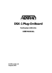
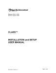
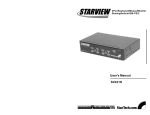
PRACTICES
Section 61109403L2-5
Issue 3, November 1997
CLEI Code: D4F1DFJ_ _ _
C A U T I O N !
SUBJECT TO ELECTROSTATIC DAMAGE
OR DECREASE IN RELIABILITY.
HANDLING PRECAUTIONS REQUIRED.
2FXS/DPO PM
FOREIGN EXCHANGE STATION/DIAL PULSE ORIGINATE DATAPORT
WITH PERFORMANCE MONITORING
INSTALLATION AND MAINTENANCE
1.
2.
3.
4.
5.
6.
CONTENTS
GENERAL ................................................................... 1
INSTALLATION ........................................................... 2
CONNECTIONS .......................................................... 4
TESTING ..................................................................... 4
MAINTENANCE .......................................................... 5
WARRANTY AND CUSTOMER SERVICE ................ 5
FIGURES
Figure 1. 2FXS/DPO ........................................................... 1
Figure 2. Circuit Path .......................................................... 3
Figure 3. Connector ............................................................ 4
Table A.
Table B.
Table C.
Table D.
Table E.
SW 4
SW 3
SW 2
SW 1
2FXS40/D3LPO
2
1109
PM
AP
REM
PM
TEST
BUSY
SW 7
TABLES
SW1 (Receive) and SW2 (Transmit) ................... 2
SW3, SW4, and SW5 Option Settings ................ 2
Manual Configuration Guide ................................ 3
Electronic Provisioning Settings .......................... 3
2FXS/DPO Faceplate Indicators ......................... 4
Figure 1. 2FXS/DPO
1. GENERAL
This practice provides installation and maintenance
information for the ADTRAN® Intelligent 2-Wire Foreign
Exchange Station/Dial Pulse Originate (2FXS/DPO PM)
Dataport with Performance Monitoring, part number
1109403L2. It is a D4 compatible channel unit and
operates in any standard D4 channel bank. Intelligent
features requires the unit to be used in the ADTRAN ACT
2300, ACT 1900 , or standard WECO® D4 channel bank
using the ADTRAN LIU-3/PM common unit. The 2FXS/
DPO PM provides an interface between a D4 channel
bank Pulse Code Modulation (PCM) backplane interface
and a 2-wire voice frequency (VF) transmission and
signaling facility. Figure 1 is an illustration of the 2FXS/
DPO PM. The unit is multifunctional and can be
provisioned to operate in the following modes:
•
•
•
•
2-Wire Foreign Exchange Station (2FXS)
Dial Pulse Originate (DPO)
Tandem FXS Mode
Private Line Auto Ringdown (PLAR)
61109.403L2-5C
Using the FXS/DPO PM in an intelligent channel bank
provides additional features and functions such as:
• Local and Remote Provisioning using either the craft
interface or ADTRAN Site Manager through a menu
driven program called EASYMENU™
• Performance monitoring of the loop
• Network and customer side monitoring and analysis
• Enhanced Test Capabilities
Revision History
Revisions to this practice include CLEI code and dip
switch settings.
Features
• Backplane interface to the Pulse Code Modulation
(PCM) bus.
• On board coder/decoder (CODEC) uses µ-law
encoding/decoding.
• Nominal 600 ohm or 900 ohm 2-Wire VF interface with
DC isolation.
Trademarks: Any brand names and product
names
included in this document
are3trademarks, registered trademarks, or trade names
Section
61109.403L2-5,
Issue
of their respective holders.
1
• Tandem or private line automatic ringdown mode with
D3 or D4 signaling.
• Transmit and receive gain/attenuation adjustable in
0.1 dB increments.
• Transmit input range of -4.5 to 1.8 dBm.
• Receive output range of -6.3 to 0.0 dBm.
• Complies with AT&T Publications 43801, 41008,
41009, and Bellcore GR-1089-CORE requirements
for Type 1 Equipment.
• Supports Calling Number Delivery and other common
(CLASSTM) service offerings according to TR TSY
000030 section 3.3.1.1.
Table A. SW1 (Receive) and SW2 (Transmit)
Attenuation Options.
Function
Add Attenuation
2. INSTALLATION
After unpacking the unit, immediately inspect it for
possible shipping damage. If damage is discovered, file
a claim immediately with the carrier and then contact
ADTRAN customer service (see section 6, Warranty and
Customer Service).
The 2FXS/DPO PM plugs directly into an ADTRAN ACT
2300/1900 or standard D4 channel bank. No installation
wiring is required. To install, grasp the 2FXS/DPO PM by
the faceplate and insert it into the backplane connector
until firmly seated.
Provisioning Options
Most options on the 2FXS/DPO are provisionable either
manually, using internal slide switches, or electronically
using a menu-driven program called EASYMENU. The
trunk processing options are found on internal slide
Switch 7 (SW7) and can only be provisioned manually.
Manual provisioning should be completed before
the 2FXS/DPO is inserted into the channel
bank. Electronic provisioning should be
completed following installation.
Manual Provisioning
Internal slide switches SW1,2, 3, 4, and SW7 are used to
manually provision and set the operational modes and
options of the unit. Figure 1 displays switch locations.
Slide switches SW1 and SW2 are used to set, receive, and
transmit attenuation. Table A displays the available options.
Slide switches SW3-1, 2, 3, 4, and SW3-5 are used to
provision the desired operation mode of the unit.
Slide switch SW4 is used to provision the trunk processing
(SD), dial pulse correction (DPC), loop or ground start (GS),
PLAR mode (PD3), tandem battery mode (TRB), tandem
start mode (TWS), dial tone (DTG), and ringback tone
(RTG).
Slide switch SW7 is used to provision the trunk processing
options: make busy lead (1G), make busy closure (L), and
busy trunk sleeve (S). Table B summarizes the option
settings for SW3, SW4, and SW7.
2
Note 1:
Note 2:
Note 3:
Selection/Setting
Amount in dB
Activate
Switch to
"On" Position
0.1 dB
SW1,2 - 6
0.2 dB
SW1,2 - 5
0.4 dB
SW1,2 - 4
0.8 dB
SW1,2 - 3
1.6 dB
SW1,2 - 2
3.2 dB
SW1,2 - 1
Factory default setting for all switches is "off."
Multiple switch activation causes a cumulative effect
on the amount of attenuation added.
The largest transmit attenuation value in 2-Wire
mode is 6.3 dB.
Table B. SW3, SW4, and SW5 Option Settings
Function
Switch
Selection
Setting
Operational Mode
Impedance
SW3-1
(Z900)
900 ohms
600 ohms
ON
OFF
TNDM Mode
SW3-2
(TNDM)
Enabled
Disabled
On
Off
PLAR Mode
SW3-3
(PLAR)
Enabled
Disabled
On
Off
FXS Mode
SW3-4
(FXS)
Enabled
Disabled
On
Off
DPO Mode
SW3-5
Enabled
(DPO)
Disabled
General Parameters
SW4-1
Enabled
(RTG)
Disabled
On
Off
On
Off
Dial Tone
SW4-2
(DTG)
Enabled
Disabled
On
Off
Tandem Mode
Signaling
SW4-3
(TWS)
Wink
Immediate
On
Off
Tandem Mode
Battery
SW4-4
(TRB)
Reverse
Normal
On
Off
PLAR Mode
Trunk Type
SW4-5
(PD3)
D3
D4
On
Off
Start Mode
SW4-6
(GS)
Group
Loop
On
Off
Dial Pulse
Correction
SW4-7
(DPC)
Enabled
Disabled
On
Off
SW4-8
Enabled
(SD)
Disabled
Trunk Processing
SW7-2
Enabled
(1G)
Disabled
On
Off
On
Off
Make Busy
Closure
SW7-3
(L)
Enabled
Disabled
On
Off
Busy Trunk Sleeve
Option during CFA
SW7-4
(S)
Enabled
Disabled
On
Off
Ringback Tone
Busy Trunk
During CFA
Make Busy
Lead 1 Ground
Section 61109403L2-5, Issue 3
61109.403L2-5C
The trunk processing options are provisioned
only by switch SW7. Electronic provisioning is
not available.
Table C provides a guide to ensure proper provisioning
of the desired channel unit mode.
Table C. Manual Configuration Guide
FXS
Loop
Start
FXS
Gnd
Start
TANDEM
Loop
Start
TANDEM
Gnd
Start
PLAR
DPO
RTG
(SW4-1)
X
X
On/Off
On/Off
On
X
DTG
(SW4-2)
X
X
On/Off
On/Off
X
X
TWS
(SW4-3)
X
X
On/Off
On/Off
X
X
TRB
(SW4-4)
X
X
On/Off
On/Off
X
X
PD3
(SW4-5)
X
X
X
X
On/Off
X
GS
(SW4-6)
Off
On
Off
On
X
X
DPC
(SW4-7)
On/Off
On/Off
X
X
X
X
SD
(SW4-8)
On/Off
On/Off
On/Off
On/Off
On/Off
On/Off
TNDM
(SW3-2)
Off
Off
On
On
Off
Off
PLAR
(SW3-3)
Off
Off
Off
Off
On
Off
FXS
(SW3-4)
On
On
Off
Off
Off
Off
DPO
(SW3-5)
Off
Off
Off
Off
Off
On
Options
Note: X = Switch position is ignored.
Electronic Provisioning
ADTRAN EASYMENU is used to electronically provision
the unit. Connect a VT 100 terminal or a computer
running a terminal emulation program to the faceplate
ADMIN port or REMOTE port using a standard male-tomale RS-232 cable. The settings for the ADMIN and
REMOTE ports are shown in Table D.
A null modem cable is required to connect the
REMOTE port directly to a terminal.
Table D. Electronic Provisioning Settings
ADMIN Port
Settings
9600 baud
No Parity
8 bits
1 stop bit
REMOTE Port
SW2 baud
No Parity
8 bits
1 stop bit
Before provisioning the unit electronically, access the
channel unit by selecting:
Channel Unit Menus
Desired slot
Provisioning
Select current operational mode
Select desired provisioning option
(3)
(1-24)
(2)
(1-4)
(1-*)
For additional information on EASYMENU operation or
the ADTRAN Site Manager, refer to the EASYMENU
User Manual, document number 61150.055L1-1 (found
in the ACT 2300/1900 System Manual, document number
2150.050-3), or the Site Manager User Manual, document
number 64150.075L1-1. For additional information about
the LIU-3/PM see the LIU-3/PM User Manual, part
number 61151.001L2-1.
Initial Turn-up
Refer to the desired operational mode in Table C for the
correct provisioning options.
Transmit Attenuation
Determine the input TLP. Then use the following formula
to calculate the amount of transmit attenuation to add to
the circuit:
Tx Attenuation=Input TLP + Internal Tx TLP of 4.5
dBm
For example, if an input TLP level of -3 dB is to produce
a level of 0dBm0 at TLP0, then the Transmit Attenuation
should be set to 1.5 dB.
Receive Attenuation
Determine the output TLP. Then use the following
formula to calculate the amount of receive attenuation to
add to the circuit:
Rx Attenuation=Internal Rx TLP of 0 dBm) - Output
TLP
For example, if 0dBm0 at TLP0 is required to produce an
Output TLP level of -3 dB, then the Receive Attenuation
should be set to 3 dB. Figure 2 provides an illustration
of attenuation settings.
Transmit Path
Tx Atten
T
Once connected, enter the password. The factory default
password is PASSWORD in all capital letters. The
password may be changed by selecting:
TDATA
0 dBm0
-4.5 to +1.8 dB
Input TLP
0- 6.3 dB
0 to -6.3 dB
Output TLP
RNPCM
0 dBm0
R
0- 6.3 dB
Common Module Menus
BCU
Configuration
Read/Write Password
61109.403L2-5C
TLPO
Rx Atten
(2)
(1)
(1)
(9)
TLPO
Receive Path
Figure 2. Circuit Path
Section 61109.403L2-5, Issue 3
3
When the option BOTH is selected, tone is placed on
both the loop and the network.
3. CONNECTIONS
The 2FXS/DPO PM occupies one card position in the D4
channel bank. The connector pin assignments are
detailed in Figure 3.
Accessing Tests Through EASYMENU
Once the unit is in normal operation, these test features
are accessed by selecting:
4. TESTING
The 2FXS/DPO performs
a self test after power on.
During this time all four
indicators turn On in a
predefined sequence
while the 2FXS/DPO
verifies proper operation
of critical circuits in the
design. After successful
completion of the self test,
all indicators function in
their normal mode.
Digital Loopback Test
The Digital Loopback Test
is used to test loopback
data coming from the
network. Received data,
or RNPCM, is latched in
during the appropriate
receive time slot. This
data is then placed on the
TDATA bus during the
unit's transmit time slot.
+5V
TDATA
RFB
RCLK
RWD
RSQ
-48F
IN
-48SD
R
BT
20HZ
28
1
29
2
30
3
31
4
32
5
33
6
34
7
35
8
FRM GND
-12V
12V GND
+12V
5V GND
TWD
TSP
TSQ
RNPCM
RFA
TDCLK
Channel Unit Menus
Desired slot
Test
These tests are service affecting.
Faceplate Indicators
The 2FXS/DPO faceplate indicators and descriptions
are explained in Table F.
36
9
37
10
38
11
39
12
40
13
41
14
42
15
43
16
44
17
45
18
2FXS/DPO
46
19
47
20
1109403L2
PM
48
21
49
22
50
23
51
24
52
25
53
26
54
27
RSP
RNDIS
-48 FRT
-48 SPRT
TFCC
2N
T
RT
RG
(3)
(1-24)
(4)
Table E. 2FXS/DPO Faceplate Indicators
AP
REM
PM
TEST
BUSY
Indicator Indication
Description
REM
Off
Green
Flashing
Unit is manually provisioned.
Unit is remotely provisioned.
Configuration/provisioning error.
PM
Off
Green
PM mode is not operating.
PM mode is operating.
TEST
Off
Yellow
All tests are inactive.
Test is active.
BUSY
Off
Green
Network and Loop On-hook.
Network, Loop, or both are Offhook.
Switch
Figure 3. Connector
Pin Assignments
AP
Selection
Depressed
Description
Alternate provisioning switch.
Changes provisioning source
from manual to remote or remote
to manual.
Network On-hook/Off-hook Test
The Network On-hook/Off-hook test is used to test
signaling sent to the network by the unit. When On-hook
Test is selected, On-hook signaling is sent to the network.
When Off-hook Test is selected, Off-hook signaling is
sent to the Network. The customer loop is forced Onhook while this test is active.
The 2FXS/DPO PM has four faceplate indicators and a
depressed provisioning switch. The front panel PM
(Performance Monitoring) indicator Flashes during
control link establishment and remains ON after the
channel unit has been remotely provisioned.
Customer Ringing Test
The Customer Ringing Test will activate the unit's ring
relay in a 2-on/4-off ring cadence, providing ringing to
the customer loop when a ring generator is properly
connected to the channel bank.
If the channel unit has been remotely provisioned, the
operator can alternate between the remote configuration
data stored in nonvolatile memory or manual switch
settings by pressing the momentary AP (Alternate
Provisioning) switch located on the front panel.
1004 Hz DRS Tone Generation Test
The 1004 Hz DRS (Digital Reference Signal) Tone
Generation test is used to send the DRS signal to the
network, loop, or both. When Network is selected, the
DRS is sent to the network from the unit. The far end unit
should measure a 1004 Hz tone at a level determined by
the circuit gain of the far end unit. When Loop is
selected, the DRS is placed on the receive path. The
loop receive level is determined by the following equation:
The REM indicator remains ON when the channel unit is
operating based on Remote Provisioning, and is OFF
when based on manual switches. If the channel unit has
never been remotely provisioned, the AP switch has no
effect and the REM indicator remains OFF . The REM
LED Flashes when an invalid operation mode is selected.
Receive Level = 0dB - Attenuation
4
Section 61109403L2-5, Issue 3
61109.403L2-5C
5. MAINTENANCE
The ADTRAN 2FXS/DPO requires no routine
maintenance to operate properly.
ADTRAN recommends that repairs on the unit not be
performed in the field. Repair services may be obtained
by returning damaged units to ADTRAN (see section 6,
Warranty and Customer Service).
6. WARRANTY AND CUSTOMER SERVICE
ADTRAN will replace or repair this product within ten years
from the date of shipment if it does not meet its published
specifications or fails while in service (see ADTRAN
Equipment Warranty, Repair, and Return Policy and
Procedure).
Return Material Authorization (RMA) is required prior to
returning equipment to ADTRAN.
For service, RMA requests, or further information, contact
one of the following numbers:
ADTRAN Technical Support ..................(800) 726-8663
Standard support hours,
Monday-Friday, 7am-7pm CST
Emergency Support:,
7 days/week, 24 hours/day
ADTRAN Sales ........................................(800) 827-0807
ADTRAN Repair/RMA .............................(205) 963-8722
Repair and Return Address
ADTRAN, Inc.
Customer Service Department
901 Explorer Boulevard
Huntsville, Alabama 35806-2807
61109.403L2-5C
Section 61109.403L2-5, Issue 3
5