1
Moving
Rehabilitation
Forward™
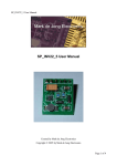
System Models:
2782 - Serial numbers 1000 and above
2759 - Serial numbers 1000 and above
ISO 13485 CERTIFIED
Intelect TranSport®/Vectra Genisys® Ultrasound Therapy Systems
TABLE OF CONTENTS
FOREWORD . . . . . . . . . . . . . . . . . . . . . . . . . . . . . . . . . . . . . . . . 1
6.6 Control Board . . . . . . . . . . . . . . . . . . . . . . . . . . . . . . . . . .27
1- SAFETY PRECAUTIONS . . . . . . . . . . . . . . . . . . . . . . . . . 2-3
6.7 Keymats. . . . . . . . . . . . . . . . . . . . . . . . . . . . . . . . . . . . . .27
1.1 Percautionary Definitions . . . . . . . . . . . . . . . . . . . . . . 2
6.8 Applicator Sound Head. . . . . . . . . . . . . . . . . . . . . . . .28
1.2 Percautionary Instructions . . . . . . . . . . . . . . . . . . . . . . 2
6.9 Applicator Probe Spring Holder . . . . . . . . . . . . . . . .29
2- THEORY OF OPERATION . . . . . . . . . . . . . . . . . . . . . . . . . . 4
6.10 Applicator PC Board. . . . . . . . . . . . . . . . . . . . . . . . . .30
2.1 Overview . . . . . . . . . . . . . . . . . . . . . . . . . . . . . . . . . . . . . 4
6.11 Applicator Cable . . . . . . . . . . . . . . . . . . . . . . . . . . . . .31
2.2 Power Supply. . . . . . . . . . . . . . . . . . . . . . . . . . . . . . . . . . 4
7- ULTRASOUND APPLICATOR CALIBRATION . . . . . . . .32
2.3 Control Board . . . . . . . . . . . . . . . . . . . . . . . . . . . . . . . . . 4
8- PARTS . . . . . . . . . . . . . . . . . . . . . . . . . . . . . . . . . . . . . . 33-39
2.4 Ultrasound Board and Applicator . . . . . . . . . . . . . . . 4
8.1 Top Assembly. . . . . . . . . . . . . . . . . . . . . . . . . . . . . . . . .33
2.5 User Interface and Accessories. . . . . . . . . . . . . . . . . . 4
8.2 Ultrasound Assembly. . . . . . . . . . . . . . . . . . . . . . . . . .34
3- NOMENCLATURE . . . . . . . . . . . . . . . . . . . . . . . . . . . . . . . 5-7
8.3 Control Board Assembly . . . . . . . . . . . . . . . . . . . . . . .35
3.1 Intelect Transport/Vectra Genisys
Ultrasound Therapy Systems . . . . . . . . . . . . . . . . . 5
8.4 Base Assembly. . . . . . . . . . . . . . . . . . . . . . . . . . . . . . . .36
3.2 Hardware and Software
Symbol Definitions . . . . . . . . . . . . . . . . . . . . . . . . . . . 6
9- SCHEMATICS . . . . . . . . . . . . . . . . . . . . . . . . . . . . . . . . 40-44
4- SPECIFICATIONS. . . . . . . . . . . . . . . . . . . . . . . . . . . . . . . . 8-9
4.1 Intelect Transport/Vectra Genisys
Ultrasound Therapy Systems . . . . . . . . . . . . . . . . . . 8
4.2 Intelect Transport/Vectra Genisys
Ultrasound Therapy Systems Specifications . . . 9
5- TROUBLESHOOTING . . . . . . . . . . . . . . . . . . . . . . . . . 10-20
5.1 Intelect Transport/Vectra Genisys
Ultrasound Therapy Systems
Error Messages . . . . . . . . . . . . . . . . . . . . . . . . . . . . . .10
5.2 Intelect Transport/Vectra Genisys
Ultrasound Therapy Systems Diagnostics. . . . . .12
5.3 Electrical Safety . . . . . . . . . . . . . . . . . . . . . . . . . . . . . . .13
5.4 Leakage . . . . . . . . . . . . . . . . . . . . . . . . . . . . . . . . . . . . .13
5.5 Visual Inspection . . . . . . . . . . . . . . . . . . . . . . . . . . . . . .14
5.6 Unit Startup and Fan Testing . . . . . . . . . . . . . . . . . . .14
5.7 Ultrasound Board Test . . . . . . . . . . . . . . . . . . . . . . . . .15
5.8 Power Supply Test. . . . . . . . . . . . . . . . . . . . . . . . . . . . .16
5.9 Ultrasound Tests . . . . . . . . . . . . . . . . . . . . . . . . . . . . . .17
5.10 Ultrasound Applicator Ouptut Test . . . . . . . . . . . .18
5.11 Ultrasound Duty Cycle Test . . . . . . . . . . . . . . . . . . .20
6- REMOVAL & REPLACEMENT . . . . . . . . . . . . . . . . . . 21-31
6.1 Separating Top From Bottom . . . . . . . . . . . . . . . . . .21
6.2 Fan . . . . . . . . . . . . . . . . . . . . . . . . . . . . . . . . . . . . . . . . . .22
6.3 Power Supply. . . . . . . . . . . . . . . . . . . . . . . . . . . . . . . . .23
6.4 Ultrasound Board . . . . . . . . . . . . . . . . . . . . . . . . . . . . .25
6.5 LCD Display . . . . . . . . . . . . . . . . . . . . . . . . . . . . . . . . . .26
8.5 Final Assembly. . . . . . . . . . . . . . . . . . . . . . . . . . . . . . . .38
10- WARRANTY . . . . . . . . . . . . . . . . . . . . . . . . . . . . . . . . . . . .45
FOREWORD
Intelect TranSport®/Vectra Genisys® Ultrasound Therapy Systems
Read, understand, and follow the safety precautions and all other information contained in this manual.
This manual contains the necessary safety and field service information for those field service technicians, certified
by Chattanooga Group, to perform field service on Intelect Transport/Vectra Genisys Ultrasound Therapy Systems.
At the time of publication, the information contained herein was current and up-to-date. However, due to
continual technological improvements and increased clinical knowledge in the field of ultrasound therapy, as
well as Chattanooga Groups policy of continual improvement, Chattanooga Group reserves the right to make
periodic changes and improvements to their equipment and documentation without any obligation on the part
of Chattanooga Group. As significant changes occur to Intelect Transport/Vectra Genisys Ultrasound Therapy
Systems, service bulletins will be made available on our website (chattgroup.com) in lieu of reprinted manuals.
Technicians repairing Intelect Transport/Vectra Genisys Ultrasound Therapy Systems agree to assume all risk and
liability associated with this process.
This system is to be used only under the supervision of a licensed practitioner.
©2008 Encore Medical, L.P. and its affiliates, Austin, Texas, USA. Any use of editorial, pictorial, or layout composition of this publication without express written consent from
Chattanooga Group of Encore Medical, L.P. is strictly prohibited. This publication was written, illustrated, and prepared for print by Chattanooga Group of Encore Medical, L.P.
1
1 SAFETY PRECAUTIONS
Intelect TranSport®/Vectra Genisys® Ultrasound Therapy Systems
1.2 PRECAUTIONARY INSTRUCTIONS
Read, understand, and follow all safety precautions
found in this manual. Below are general safety
precautions that must be read and understood
before attempting any service techniques on these
systems.
1.1 PRECAUTIONARY SYMBOL DEFINITIONS
The precautionary instructions found in this manual
are indicated by specific symbols. Understand these
symbols and their definitions before operating or
servicing this equipment. The definitions of these
symbols are as follows:
A. CAUTION
• Read, understand and practice the
precautionary and operating instructions. Know
the limitations and hazards associated with
using any ultrasound device. Observe the
precautionary and operational decals placed on
the unit.
• Do not operate the unit in an environment of
short-wave diathermy use.
• The Ultrasound modality should be routinely
checked to determine that all controls function
normally using the information provided within
this manual.
• Use of controls or adjustments or performance
of procedures other than those specified herein
may result in hazardous exposure to
ultrasonic energy.
• Do Not use sharp objects such as a pencil point
or ballpoint pen to operate the buttons on the
control panel as damage may result.
• Operate, transport and store this unit in
temperatures between 59 °F and 104 °F (15 °C
and 40 °C), with Relative Humidity ranging from
30%-60%.
• Inappropriate handling of, and subjecting the
ultrasound applicator to physical abuse, may
adversely affect its characteristics.
• Inspect Applicator for cracks, which may allow
the ingress of conductive fluid before each use.
• Inspect all cables, and associated connectors
before each use.
Text with a “CAUTION” indicator will explain
possible safety infractions that have the
potential to cause minor to moderate injury or
damage to equipment.
B. WARNING
Text with a “WARNING” indicator will explain
possible safety infractions that will potentially
cause serious injury and equipment damage.
C. DANGER
Text with a “DANGER” indicator will explain
possible safety infractions that are imminently
hazardous situations that would result in
death or serious injury.
D. EXPLOSION HAZARD
Do not use this equipment in the
presence of flammable anesthetics. This
symbol is also prominently displayed on
the serial number plate of the unit.
E. DANGEROUS VOLTAGE
Text with a “Dangerous Voltage” indicator
serves to inform the Service Technician of
possible hazards resulting in the electrical
charge retained by faulty power supplies.
F. CORROSIVE HAZARD (NiMH Battery)
Text with a “Corrosive Hazard” indicator
will explain possible safety infractions if
the chemical components of this product
are exposed to air, skin or other materials.
NOTE:
Throughout this manual “NOTE” may be found.
The Notes are helpful information to aid in the
particular area or function being described.
2
1 SAFETY PRECAUTIONS
Intelect TranSport®/Vectra Genisys® Ultrasound Therapy Systems
1.2 SAFETY PRECAUTIONS CONTINUED
• Do not apply the Ultrasound Applicator to the
patient during the Head Warming period.
Applicator must remain in Applicator Hook during
the Head Warming period.
• Use only degassed water in power meter for
testing Ultrasound Applicators. Use of other types
of water will cause false test results. see page 12
for degassed water recipes.
• Use of other brands or types of tools, equipment,
fixtures, materials, and supplies other than those
specifically listed on page 12 will give bad test
and calibration results.
• If proper equipment is not available or cannot be
obtained, send the Ultrasound Applicators to the
factory for calibration.
• Do not aerate water when filling power meter.
• Unplug the unit from the power source and/or
remove Battery before attempting any removal or
replacement procedures to prevent electrical
shock.
• Dielectric Withstand Test must always be
performed after a Power Supply has been
replaced. Field technicians unequipped to preform
the Dielectric Withstand Test should contact the
manufacturer for Power Supply replacement.
• Handle Power Supply shield with caution.
Penetration of the shield may result in
damage to the unit and/or personal injury.
• The Power Supply will retain high voltage in
the Power Supply Capacitor C4. Discharge
Capacitor using a multimeter prior to any
service of the Power Supply
• Applicator must be calibrated after removal
and replacement of any part, using an
Ohmic UPM DT 10 or UPM DT 100.
Failure to calibrate a repaired Applicator,
using the proper equipment, may result in
serious injury or harm to the patient.
3
2 THEORY OF OPERATION
Intelect TranSport®/Vectra Genisys® Ultrasound Therapy Systems
2.1 OVERVIEW
The Intelect Transport/Vectra Genisys Ultrasound Therapy Systems are comprised of several PC board
assemblies housed within a common enclosure. These assemblies each support a distinct function in the
product. The basic elements are User Interface, Control Board, Ultrasound Board, Ultrasound Applicator, and
Power Supply.
2.2 POWER SUPPLY
A universal input Power Supply provides all parts of the system with 24 VDC. The supply is connected to
the mains at all times when the cord is attached. The power switch on the top of the unit, switches the 24
VDC output of the Power Supply to the different components in the system. The 24 VDC supply is regulated
locally at each PC Board as required.
2.3 CONTROL BOARD
The Control Board serves just as its name implies. It controls the operation of the Ultrasound Board, User
Interface and optional accessories. The Control Board communicates to the Ultrasound Board. The Control
Board drives the Display. The Control Board reads the menu buttons. The Control Board also reads the
amplitude and the Contrast Control on the system. Sound output is generated by the Control Board and
routed to an internal speaker.
2.4 ULTRASOUND BOARD AND APPLICATOR
The Ultrasound Board generates the 1 or 3.3 MHz output to drive the ultrasound Sound Head. The
Ultrasound Board is accessed much like an I/O port by the Control Board. It can provide current and voltage
information about the ultrasound output of the board. The calibration data for the Sound Head is passed
through the Ultrasound Board from the Applicator up to the Control Board. By storing the calibration data
in the Applicator there is no calibration necessary for the Ultrasound Board. Calibrated Chattanooga Group
Ultrasound Applicators, designed for the Intelect Transport/Vectra Genisys Ultrasound Therapy Systems, can
be connected and operated on any Intelect Transport/Vectra Genisys Therapy System to provide accurate
coupling and output.
2.5 USER INTERFACE AND ACCESSORIES
The LCD display panel provides the operator visible feedback in the way of menu choices. Pressing the menu
buttons makes selections from the menus. The Control Board interprets these user inputs and responds
accordingly. Audible feedback is given as well for events such as key presses and end of treatment.
The Optional Battery mounts in the system bottom and supplies 24 VDC to the power supply. The Power
Supply distributes the power required to the system as needed. The charging circuit for the battery is
incorporated on the Control Board. An icon on the display reflects the available amount of charge in the
battery. When the system is connected to an approved power outlet and a Battery is installed in the system,
the system will charge the Battery to full capacity. The incorporated charger will not overcharge the Battery.
4
3 NOMENCLATURE
Intelect TranSport®/Vectra Genisys® Ultrasound Therapy Systems
components of the Intelect Transport/Vectra Genisys
Ultrasound Therapy Systems.
Know the components and their functions before
performing any operation on or service to the
Intelect Transport/Vectra Genisys Ultrasound Therapy
Systems.
3.1 INTELECT TRANSPORT/VECTRA
GENISYS ULTRASOUND THERAPY
SYSTEMS
The nomenclature graphics below, Figure 3.1,
indicates the general locations of the exterior
Power
On/Off
LCD Intensity/
Contrast Dial
LCD
Sound Head
Clinical
Library
Time
Duty Cycle/
Up Arrow
Head Warming/
Back
Power Cord
Plynth
Intensity
LED Indicator
(Output Power)
Intensity Selection
Watts/Watts per cm² /
Parameter Display / Enter
Applicator
Applicator
Holder
Stop
Pause
Frequency/
Down Arrow
Accessory
Panel
Start
Power Cord
Connection
Battery
Compartment
Serial
Decal
FIGURE 3.1
5
Ultrasound
Applicator
Connection
3 NOMENCLATURE
Intelect TranSport®/Vectra Genisys® Ultrasound Therapy Systems
3.2 HARDWARE AND SOFTWARE SYMBOL DEFINITIONS
The symbols below are found on the system as
well as within the software. These symbols are
defined for the purpose of recognition and
functionality when operating or performing
service on the Intelect Transport/Vectra Genisys
Ultrasound Therapy Systems.
Know the symbols and their definitions before
performing any operation of or service to the
Intelect Transport/Vectra Genisys Ultrasound Therapy
Systems.
Intelect Transport/Vectra Genisys Ultrasound Therapy Systems Hardware Symbols
Power On/Off
The Power On/Off button controls the flow of electricity to the unit. Illuminates steady when system
is On. Flashes when power is available.
LCD
The LCD (Liquid Crystal Display) allows the user to view and monitor the information displayed before,
during, and after therapy.
Clinical Library
Select this button to access the following functions:
• Retrieve User Protocol
• Restore Factory Settings
• Restore Factory Protocols
• Languages
• View Unit Information
Time
Press the Up or Down arrow buttons to set total treatment time of therapy.
Back
Use this button to return to the previous window.
STOP
Select this button to stop a treatment session.
Down Arrow
When the window displays a list of options, press the Down Arrow button to scroll down the list.
Pause
Press this button to pause and restart therapy sessions.
Sound Head
The aluminum face of the applicator that contacts the patient’s skin. It covers a transducer mechanism
that converts electrical energy to mechanical energy in the form of a vibrating crystal.
LED Indicator (Output Power)
When illuminated, this green light signifies that ultrasound energy is being emitted from the
Sound Head.
Applicator
The hand held assembly used to deliver ultrasonic energy. The Applicator includes the Sound Head,
Transducer, and related electronics.
6
3 NOMENCLATURE
Intelect TranSport®/Vectra Genisys® Ultrasound Therapy Systems
3.2 HARDWARE AND SOFTWARE SYMBOL DEFINITIONS CONTINUED
Ultrasound Applicator Connection
This port serves as the connection point between the unit and the Ultrasound Applicator.
START
Select Start to begin a treatment session.
Accept and Return
Select to accept menu selection and to return to the home screen
INTENSITY
Use the up or down arrow on the Intensity button to adjust Ultrasound Intensity to the
prescribed level.
Duty Cycle
Press to select and display the Duty Cycle of the Ultrasound as prescribed. Options available are: 10%,
20%, 50,% or Continuous (100%).
Up Arrow
When the window displays a list of options, press the Up Arrow button to scroll up the list.
Battery Indicator
When displayed on the LCD, this symbol indicates the Battery pack option is present on the unit. This
symbol also displays the charge status of the Battery.
LCD Intensity/Contrast Dial
If the intensity of the LCD display diminishes, turn the dial until the Display contrast is optimal.
Charge Indicator
This symbol displays when the unit is connected to Mains Power and the Battery Pack is charging.
Frequency
Press to change Frequency to 3 MHz or 1 MHz.
Intensity Display
Press to display “Watts” or “Watts per cm²“ for the output of the ultrasound.
Head Warming
Press to turn Off or On the Head Warming feature of the system.
Increase
Found in two locations on the system, press to increase session time and/or ultrasound intensity
respectively.
Decrease
Found in two locations on the system, press to decrease session time and/or ultrasound
intensity respectively.
NOTE: During Battery operation, if the unit is left on, but is not active for more than five minutes, it
will power off to conserve Battery power. To restore power, press the Power On/Off button.
7
4 SPECIFICATIONS
Intelect TranSport®/Vectra Genisys® Ultrasound Therapy Systems
4.1 INTELECT TRANSPORT/VECTRA GENISYS ULTRASOUND THERAPY SYSTEMS
Figure 4.1 below provides physical details of the
Intelect Transport/Vectra Genisys Ultrasound Therapy
Systems. This section also provides ultrasound
specifications to aid in troubleshooting.
Refer to this section when performing
troubleshooting, replacement, and repair of the
Intelect Transport/Vectra Genisys Ultrasound Therapy
Systems.
A. Intelect Transport/Vectra Genisys Ultrasound Therapy Systems Physical Specifications
DEPTH
HEIGHT
WIDTH
FIGURE 4.1
Dimensions
Width.. .. .. .. .. .. .. .. .. .. .. .. .. .. .. .. .. .. .. .. .. .. .. .. .. .. .. .. .. .. .. 28.8 cm (11.3")
Height . .. .. .. .. .. .. .. .. .. .. .. .. .. .. .. .. .. .. .. .. .. .. .. .. .. .. .. .. .. .. . 16.3 cm (6.4")
Depth.. .. .. .. .. .. .. .. .. .. .. .. .. .. .. .. .. .. .. .. .. .. .. .. .. .. .. .. .. .. .. 32.8 cm (12.9")
Weight
Standard Weight (with base) .. .. .. .. .. .. .. .. .. .. .. .. .. .. .. .. .. .. .2.3 kg (5.07 lb)
Battery Pack. .. .. .. .. .. .. .. .. .. .. .. .. .. .. .. .. .. .. .. .. .. .. .. .. .. .. .0.85 kg (1.87 lb )
Power
Input. .. .. .. .. .. .. .. .. .. .. .. .. .. .. .. .. .. .. .. .. .. .. . 100 - 240 VAC, 50/60 Hz 75 VA
Output. .. .. .. .. .. .. .. .. .. .. .. .. .. .. .. .. .. .. .. .. .. .. .. .. .. .. .. .. .. .. .. . +24 V, 1.0 A
Electrical Class .. .. .. .. .. .. .. .. .. .. .. .. .. .. .. .. .. .. .. .. .. .. .. .. .. .. .. .. .. .. .. CLASS I
Electrical Type
Ultrasound TYPE B.. .. .. .. .. .. .. .. .. .. .. .. .. .. .. .. .. .. .. .. .. .. .. .. .. .. .. .. .. .. .
Operating Environment
Temperature .. .. .. .. .. .. .. .. .. .. .. .. .. .. .. .. .. .. .. .. .. ..Between 59° F and 104° F
(15° C and 40° C)
Relative Humidity .. .. .. .. .. .. .. .. .. .. .. .. .. .. .. .. .. .. .. .. .. .. .. .. .. .. .. 30%-60%
Atmospheric Pressure .. .. .. .. .. .. .. .. .. .. .. .. .. .. .. .. .. .. .. .. .. .. . 950-1,050 h Pa
Complies with:
9700675
Listed by Intertek Testing Services NA Inc.
Conforms to UL Standard 60601-1
Certified to CAN/CSA Standard C22.2 No.
601.1-M90 w/A2
Compliant to IEC/EN 60601-1,
IEC 60601-1-2, 60601-2-5
Battery Type . .. .. .. .. .. .. .. .. .. .. .. .. .. .. .. .. .. .. .. .. Nickel Metal Hydride (NiMH)
(1.2 V x 20 size AA)
8
4 SPECIFICATIONS
Intelect TranSport®/Vectra Genisys® Ultrasound Therapy Systems
4.2 INTELECT TRANSPORT/VECTRA GENISYS ULTRASOUND THERAPY
SYSTEMS ULTRASOUND SPECIFICATIONS
This section provides the necessary ultrasound specifications to aid in troubleshooting.
Refer to these specifications as necessary when troubleshooting the ultrasound PC Board and Applicators.
A. Ultrasound
Frequency . . . . . . . . 1 MHz, ± 5%; 3.3 MHz, ± 5%
Duty Cycles . . . 10%, 20%, 50%, and Continuous
Pulse Frequency. . . . . . . . . . . . . . . . . . . . . . . . .100 Hz
Pulse Duration . .1 mSec, ± 20%; 2 mSec, ± 20%
5 mSec, ± 20%
Output Power
10 cm2 Crystal . . . . . . . . . . . . 0-20 Watts at 1 MHz,
0-10 Watts at 3.3 MHz
5 cm2 Crystal . . . . . . . . 0-10 Watts, 1 and 3.3 MHz
2 cm2 Crystal . . . . . . . . . .0-4 Watts, 1 and 3.3 MHz
1 cm2 Crystal . . . . . . . . . . .0-2 Watts, 3.3 MHz Only
Amplitude . 0 - 2.5 w/cm2 in Continuous mode,
0-3 w/cm2 in Duty Cycle modes
Output accuracy . . . . . . . . . .± 20% above 10% of
maximum
Temporal Peak to Average Ratios:
2:1, ± 20%, at 50% Duty Cycle
5:1, ± 20%, at 20% Duty Cycle
9:1, ± 20%, at 10% Duty Cycle
Beam Non uniformity Ratio. . . .. . . . . . . . . . 5.0 : 1
maximum
Beam Type . . . . . . . . . . . . . . . . . . . . . . . . . Collimating
Effective Radiating Areas
10 cm2 Crystal - 6.8 cm2 - 10.0 cm2
5 cm2 Crystal - 3.5 cm2 - 5.0 cm2
2 cm2 Crystal - 1.4 cm2 - 2.0 cm2
1 cm2 Crystal - 0.7 cm2 - 1.0 cm2
Treatment Time . . . . . . . . . . . . . . . . . . 1-30 Minutes
B. Head Warming Feature Specifications
The Head Warming feature of an Intelect
Transport/Vectra Genisys Ultrasound Therapy
System utilizes Ultrasound output resulting in
warming of the Applicator to increase patient
comfort.
With Head Warming enabled, ultrasound is
emitted without pressing the Start button. The
Applicator LED will not illuminate during the
Head Warming period. Display will indicate
"Warming".
Output . . . . 0 - 50% Cycling of maximum power
Frequency . . . . . . . . . . . . . . . . . . . . . . . . . . . .3.3 MHz
Sound Head Temperature . . . . . . 85 °F - 110 °F
(29.4 °C - 43.3 °C)
Do not apply the Ultrasound Applicator to
the patient during the Head Warming period.
Applicator must remain in applicator hook during
the Head Warming period.
9
5 TROUBLESHOOTING
Intelect TranSport®/Vectra Genisys® Ultrasound Therapy Systems
5.1 INTELECT TRANSPORT/VECTRA GENISYS
ULTRASOUND THERAPY SYSTEMS ERROR MESSAGES
a “Bad Board” only.
A. The following information is provided as an aid
No component level troubleshooting
in defining the Software Error Messages of the
information is or will be provided by
Intelect Transport/Vectra Genisys Ultrasound
Chattanooga Group for field troubleshooting of
Therapy Systems. Once a particular error
board components.
message is defined, the information will also list
B. Once a particular PC board has been
probable causes and possible remedies. Once
determined as bad, refer to the appropriate
the problem area is determined, subsequent
removal and replacement section for the
tests for verification will be necessary to
board affected and follow the instructions for
determine a “Bad Board”.
replacement of the board.
All Troubleshooting and tests will be to validate
ERROR
CODE
ERROR
TYPE
DEFINITION
PROBABLE CAUSES
POSSIBLE REMEDY
USER CORRECTABLE WARNING MESSAGES
Icon
Sound Head over temp
Sound Head has overheated to a
temperature that could cause damage
to the crystal
Icon
No Applicator plugged into
system
Applicator not plugged into system
connector
Applicator connector not completely
seated in system connector
Applicator Cable disconnected from
Applicator PCB
1. Turn Off Head Warming feature
2. Allow Sound Head to cool before
continuing therapy
3. Connect a known good Applicator to
the system and try again. If system
works properly, re-calibrate Applicator
or replace with new Applicator.
4. Replace Applicator PC Board
Plug Applicator into system
Make certain Applicator connector is
completely seated in system connector
Connect Applicator Cable to Applicator
PCB
Replace with new Applicator Cable
Applicator Cable damaged
Replace Applicator PC Board
Applicator not calibrated
Calibrate Applicator
Replace Ultrasound Board
Icon
100
WARN_US_
UNPLUGGED
101
200
201
202
203
WARN_US_
APPL_
BECAME_
UNPLUGGED
ERR_EEPROM
ERR_APPL_
SAVE_CAL_
DATA
ERR_APPL_NOT_
CAL'D_OK
ERR_APPL_
SAVE_TIMEOUT
Battery plugged into system
but not
recognized by the unit
Technician attempted to
calibrate an Ultrasound
Applicator but none is plugged
into system
Applicator came unplugged
from system while
administering therapy
Error accessing the internal
EEPROM used to store system
configuration settings and
protocols
Error attempting to save data
to applicator EEPROM during
Applicator calibration
General error attempting to
calibrate an Applicator
Error attempting to save data
to Applicator EEPROM during
Applicator calibration
Bad Ultrasound Board
Bad Battery
Control Board damaged
Applicator not plugged into system
connector
Applicator connector not completely
seated in system connector
Applicator Cable disconnected from
Applicator PCB
Applicator Cable damaged
Bad Control Board
Replace the Battery
Replace the Control Board
1. Plug Applicator into system
2. Make certain Applicator connector is
completely seated in system connector
3. Connect Applicator Cable to Applicator
PCB
4. Replace with new Applicator Cable
5. Replace Applicator PC Board
Replace Control Board
Bad Applicator
1. Replace with new Applicator Cable
Bad Applicator Cable
2. Replace Applicator PC Board
Applicator PCB Connector Bad
3. Replace with known good Applicator
Bad Ultrasound Board
4. Replace Ultrasound Board
10
5 TROUBLESHOOTING
Intelect TranSport®/Vectra Genisys® Ultrasound Therapy Systems
5.1 INTELECT TRANSPORT/VECTRA GENISYS ULTRASOUND THERAPY
SYSTEMS ERROR MESSAGES CONTINUED
ERROR
CODE
ERROR
TYPE
DEFINITION
PROBABLE CAUSES
POSSIBLE REMEDY
USER CORRECTABLE WARNING MESSAGES
Some type of critical Ultrasound Board
error has occurred
No Ultrasound Board is detected in unit
300
CRIT_ERR_US_BOARD
301
CRIT_ERR_US_BOARD
NOT_DETECTED
302
CRIT_ERR_US_RESET
303
CRIT_ERR_US_BOARD_ Error reading from Ultrasound Board
READ
304
CRIT_ERR_US_BOARD_ Error writing to Ultrasound Board
WRITE
CRIT_ERR_US_BOARD_ Error calibrating Applicator
CALIBRATION_ERROR
305
Ultrasound Board to Control Board Connecting
Header loose or disconnected
Bad Ultrasound Board
Bad Control Board
1. Reseat Connecting Header into Control Board
2. Replace Ultrasound Board
3. Replace Control Board
Ultrasound Board has reset for some
unknown reason
NONE
No indication of problem and no
ultrasound output from the Applicator
Probe Spring Holder cracked or broken
Replace Probe Spring Holder
NONE
Interrupted ultrasound output from
Applicator
Bad Applicator Cable
Replace Applicator Cable
11
5 TROUBLESHOOTING
Intelect TranSport®/Vectra Genisys® Ultrasound Therapy Systems
5.2 INTELECT TRANSPORT/VECTRA GENISYS
ULTRASOUND THERAPY SYSTEMS
DIAGNOSTICS
A. General
1. The following information is intended to aid in
troubleshooting the major components of the
Intelect Transport/Vectra Genisys Ultrasound
Therapy Systems to “Board Level” only. These
tests are FACTORY standard testing procedures
and methods used at the factory before
shipment of any Intelect Transport/Vectra
Genisys Ultrasound Therapy Systems.
2. Due to the complex nature of the technology
utilized by Chattanooga Group, the
recommended troubleshooting techniques
are to determine “Bad Board” and board
replacement only. No board component
level troubleshooting is recommended nor
will information or parts be supplied by
Chattanooga Group. Any board component
level troubleshooting performed will be at
sole risk and liability of the Service Technician
performing such troubleshooting techniques.
B. Special Tools, Fixtures & Materials Required
1. Certain tests require the use of special tools
and/or fixtures. These will be listed at the
particular test where they are required.
Testing with any other special tool or fixture
other than those stated could give erroneous
readings or test results. Always perform the
tests exactly as stated to ensure accurate
results.
2. Scope and other standard test equipment
settings will be listed for each test performed
to aid in performing the test to FACTORY
standards and ensure proper readings.
3. The troubleshooting and repair of the
Intelect Transport/Vectra Genisys Ultrasound
Therapy Systems should be performed only by
authorized technicians trained and certified by
Chattanooga Group.
C. Equipment Required
• Digital Multimeter
• Milliohm Meter
• Applicators
• Dielectric Withstand (Hi-Pot) and ground
resistance tester
• Orange Stick
•
•
•
•
•
•
NOTE:
Adjust Dielectric Withstand tester to
indicate fault with 120k Ohm Load across
the output when at specified test voltage.
# 1 Phillips Screwdriver
# 2 Phillips Screwdriver
Insulated Needle Nose Pliers
10k Resistor
Ohmic Instruments UPM DT 10 or UPM
DT 100 Ultrasound Power Meter
Degassed Water (< 5 ppm) for Ultrasound
Power Meter
Recipe(s) for Degassed Water
1) Boil distilled water for 30 minutes. Place
water in a canning jar, and cover. Allow to
cool to room temperature of approximately
70 °F (21 °C). May be refrigerated to aid
cooling time.
or
2) Bring distilled water to a boil. Place the
container under vacuum for 5 to 10 minutes.
Use a Dissolved Oxygen Test Kit to test
oxygen level of degassed water.
NOTE:
Canning jars are ideal storage and transport
containers for degassed water. In order to
minimize aeration of degassed water during
transport fill to a positive meniscus and slide the
lid over the surface. Seal tightly.
When pouring degassed water into and out of
containers pour slowly down the side of the
container to minimize aeration.
Do not use tap water or distilled water in the
ultrasound power meter. Use only degassed
water in order to obtain correct test results.
The chart below illustrates the oxygen content
of degassed, tap, and distilled Water.
WATER TYPE
Degassed
(per recipe 1 or 2)
ppm of Oxygen
Less than 5 ppm
Tap Water
Up to 35 ppm
Distilled Water
Up to 20 ppm
D. Full Functional Tests
Perform the tests found in this section to verify
full functionality of new Intelect Transport/
Vectra Genisys Ultrasound Therapy Systems
and accessories.
12
5 TROUBLESHOOTING
Intelect TranSport®/Vectra Genisys® Ultrasound Therapy Systems
5.3 ELECTRICAL SAFETY
The Intelect Transport/Vectra Genisys Ultrasound
Therapy Systems has been tested to IEC/EN
60601-1, Standard for Safety for Medical
Equipment.
NOTE:
This device complies with current leakage,
ground continuity, and dielectric withstand
(Hi-Pot) limits as prescribed by IEC/EN/UL
60601-1 and CSA/CAN 601.1 Medical Electrical,
Part 1: General Requirements for Safety.
9700675
Listed by Intertek Testing Services NA Inc.
Conforms to UL Standard 60601-1
Certified to CAN/CSA Standard C22.2 No.
601.1-M90 w/A2
Compliant to IEC/EN 60601-1,
IEC 60601-1-2, 60601-2-5
Facility, local and national limits and test
methods may vary.
Power Requirements
Models: 2782 and 2759 . . . . . . Input : 100-240VAC
(Serial numbers 1000 and above) 75 VA, 50/60 Hz
5.4 LEAKAGE
Conduct all necessary leakage tests as required
per NFPA 99 (National Fire Protection Association)
“Health Care Facility” standards.
Unit failing Dielectric Withstand or Leakage tests
could indicate serious internal problems.
Do not place unit back into service! Send unit to
factory for repair. Do not attempt to repair.
13
5 TROUBLESHOOTING
Intelect TranSport®/Vectra Genisys® Ultrasound Therapy Systems
5.5 VISUAL INSPECTION
Visually inspect the Intelect Transport/Vectra
Genisys Ultrasound Therapy Systems. A visual
inspection can, to an experienced technician,
indicate possible abuse of the unit and internal
problems.
5.6 UNIT STARTUP AND FAN TESTING
A. Test
1. Place unit face up on work surface.
2. Connect Power Cord to unit and plug into
proper power receptacle.
3. Connect an Applicator to the unit.
4. Turn system on. Adjust the Intensity up and
press Start. The fan will begin to run, after the
audible beep tones.
5. Place hand at the back of system, near
Contrast Control, to verify Fan is blowing out.
Refer to Figure 5.1.
B. Test Results
1. Unit will not start, unit failed test.
a) Possible bad Main Power Switch.
b) Possible bad Power Supply.
c) Possible bad power outlet or Mains Power
Cord.
d) Possible bad Ultrasound Board.
2. Treatment will not start up.
a) Applicator not connected.
b) Possible bad Ultrasound Board.
c) Possible bad Control Board.
3. Screen does not display, unit failed test.
a) Contrast Control needs adjusting.
b) Possible bad Display.
c) Possible bad Control Board.
d) Possible bad Power Supply.
e) Visually check power LED. If flashing, the
Power Supply is good. Replace the Control
Board.
f ) If not flashing perform the Ultrasound
Board test to check the Ultrasound Board.
Refer to section 5.7 page 15. If the Power
Supply functions replace the Ultrasound
Board.
4. Fan not blowing outward, unit failed test
a) Fan blowing inward.
Fan wired wrong. Rewire or replace Fan.
5. Fan not blowing.
NOTE:
The Fan only functions when Ultrasound is
being emitted from the Sound Head.
a) Possible bad Fan.
b) Possible bad Power Supply.
c) Possible bad Control Board.
VERIFY FAN IS
BLOWING OUT
FIGURE 5.1
14
5 TROUBLESHOOTING
Intelect TranSport®/Vectra Genisys® Ultrasound Therapy Systems
5.7 ULTRASOUND BOARD TEST
NOTE:
This test is designed to eliminate or verify a
problem with the Ultrasound Board.
A. Test
1. Separate top from bottom. Refer to 6.1,
part C.
2. Disconnect the Power Supply Harness from
the Control Board. Lay the unit open.
Refer to Figure 5.2.
3. Remove the Ultrasound Board. Refer to 6.4,
steps 2 and 3.
NOTE:
The Ultrasound/Control Board Header may
stay attached to either the Ultrasound Board
or the Control Board. It may be necessary to
remove the Header for installation.
4. Place the top of the unit back on the bottom
of the unit. While holding the top and
bottom together, with the Ultrasound Board
missing, plug the unit back into the Mains
Power.
5. Press the power button to verify that the unit
turns on.
NOTE:
The Power On/Off button will flash when
plugged into Mains Power if the Ultrasound
Board is not functioning properly.
B. Test Results
1. Unit will power up, unit passed test.
a) Replace the Ultrasound Board.
2. Screen does not display, unit failed test.
a) Contrast Control needs adjusting.
b) Possible bad Display.
c) Possible bad Control Board.
d) Possible bad Power Supply.
ULTRASOUND
BOARD
FIGURE 5.2
15
5 TROUBLESHOOTING
Intelect TranSport®/Vectra Genisys® Ultrasound Therapy Systems
5.8 POWER SUPPLY TEST
A. Test
1. Separate top from bottom. Refer to 6.1,
part C.
2. Disconnect the Power Supply Harness from
the Control Board. Lay the unit open.
3. Using a multimeter, hold the red wire of the
multimeter to the prong on the connector
for the red wire of the Power Supply Harness.
Hold the black wire of the multimeter to
the prong on the connector for the black
wire of the Power Supply Harness. Refer to
Figure 5.3.
B. Test Results
1. Power Supply reads approximately 24 VDC,
Power Supply is good.
2. Power Supply does not reads approximately
24 VDC, Power Supply failed test.
a) Replace Power Supply.
FIGURE 5.3
16
5 TROUBLESHOOTING
Intelect TranSport®/Vectra Genisys® Ultrasound Therapy Systems
5.9 ULTRASOUND TESTS
A. Equipment Required for 5.9 and 5.10
• Degassed Water. Refer to page 12 for
degassed water recipes
• Ohmic Instruments UPM DT 10 or UPM DT 100
Ultrasound Power Meter
• Known good Ultrasound Applicator
NOTE:
Use any Ultrasound Applicator supplied with a
Chattanooga Group unit for this test.
B. Ultrasound Applicator Identification
Test Procedures
1. Without Ultrasound Applicator installed,
turn unit on.
2. Look at the Display center. The Applicator
not detected icon should appear. Refer to
Figure 5.4.
3. Connect the Applicator into Applicator
Receptacle. Refer to Figure 5.5. Watch
Applicator LED while connecting to system.
The LED should flash green five times.
NOTE:
The flashing green light indicates that the
Applicator is programmed and calibrated.
4. Look at the display center. The Applicator
detected icon should appear. Refer to
Figure 5.6.
C. Ultrasound Applicator Identification
Test Results
1. Unit operates as described in steps 2 and 4.
a) Unit passed test.
2. “NO CAL” icon displays center of system
Display.
a) Applicator not calibrated.
b) Possible bad Applicator Cable. Re-test
with known good Applicator.
c) Possible bad Ultrasound Board.
3. Not detected icon displayed after ten
seconds of Applicator being plugged in.
a) Possible bad Applicator or Applicator
Cable. Re-test with known good
Applicator.
b) Possible bad Ultrasound Board.
FIGURE 5.4
FIGURE 5.5
FIGURE 5.6
17
5 TROUBLESHOOTING
Intelect TranSport®/Vectra Genisys® Ultrasound Therapy Systems
5.10 ULTRASOUND APPLICATOR OUTPUT TEST
NOTE:
The position of the Applicator over the
stainless steel cone is critical to the test results.
The Applicator must be level and centered.
Perform this test using all available Ultrasound
Applicators used with the system being tested.
NOTE:
See page 17 for a list of equipment required for
Output Tests.
A. Ultrasound Applicator Output Test
Procedures
1. Set up Ohmic Instruments UPM DT 10 or
UPM DT 100 ultrasound power meter per
operator’s instructions and fill test reservoir with
degassed water.
2 Place an Applicator into the power meter
holder. Make certain the Applicator’s Sound
Head is completely submerged in the
degassed water and centered directly over
the stainless steel cone.
Refer to Figure 5.7.
3. Zero or Tare the power meter.
4. Turn the unit on.
5. Press the Intensity Display button until “Watts”
appears in the intensity area of the Display.
6. Increase Intensity to maximum.
7. Press “Start”.
8. Press the Frequency button until "1 MHz” is
displayed in the frequency area of Display.
9. Compare power meter readings to Figure
5.8 for each of the power settings listed in
the chart.
10. Press the Frequency button until “3.3 MHz” is
displayed in the frequency area of Display.
Repeat test and compare readings to
Figure 5.8.
B. Ultrasound Applicator Output Test Results
1. Output ranges fall within the specified
ranges as listed in Figure 5.8.
Unit passed test.
2. Readings fall outside specified ranges of
Figure 5.8.
a) Possible bad degassed water in power
meter.
b) Possible use of power meter other than
Ohmic Instruments UPM DT 10 or
UPM DT 100 ultrasound power meter.
c) Possible bad or out of calibration Applicator.
d) Check Ultrasound Board.
e) Check Control Board.
FIGURE 5.7
APPLICATOR OUTPUT SPECIFICATIONS
APPLICATOR SIZE
POWER SETTING
WATTS
OUTPUT RANGE
1 cm2
1*
2*
0.8 - 1.2
1.6 - 2.4
2 cm2
1
2
4
0.8 - 1.2
1.6 - 2.4
3.2 - 4.8
5 cm2
1
2
5
10
0.8 - 1.2
1.6 - 2.4
4.0 - 6.0
8.0 - 12.0
10 cm2
1
5
10
15**
20**
0.8 - 1.2
4.0 - 6.0
8.0 - 12.0
12.0 - 18.0
16.0 - 24.0
* 3.3 MHz Only
**1.0 MHz Only
FIGURE 5.8
18
5 TROUBLESHOOTING
Intelect TranSport®/Vectra Genisys® Ultrasound Therapy Systems
5.10 ULTRASOUND APPLICATOR OUTPUT TEST
(CONTINUED)
C. Timer Control/End of Treatment Test
NOTE:
Prior to testing, verify that Head Warming is
off. Head Warming emitts ultrasound and
the intensity will not reset to zero if Head
Warming is on.
1. Turn on the unit.
2 Plug in an Applicator.
3. The Intensity Display button can read
“Watts” or "Watts per cm²" in the intensity
area of the Display.
4. Increase Intensity to 0.1 MHz
5. Set the time to 1 minute.
6. Press “Start”.
7. Verify that the green light on the Applicator
goes out when the timer reaches zero and
that the intensity resets to zero on the
display.
19
5 TROUBLESHOOTING
Intelect TranSport®/Vectra Genisys® Ultrasound Therapy Systems
5.11 ULTRASOUND DUTY CYCLE TEST
Perform this test using all Ultrasound Applicators
used with the system being tested.
A. Ultrasound Duty Cycle Test Procedures
1. Set up Ohmic Instruments UPM DT 10 or
UPM DT 100 ultrasound power meter per
operator’s instructions and fill test reservoir
with degassed water.
e) Check Ultrasound Board.
f) Check Control Board.
DUTY CYCLE SPECIFICATIONS
Use only degassed water in power meter for testing
ultrasound applicators. Use of other types of
water will cause false test results. See page 12 for
degassed water recipes.
Do not aerate water when filling power meter.
OUTPUT FOR 10%, 20%
AND 50%
DUTY CYCLES
DUTY CYCLE
OUTPUT RANGE
1 cm²
at 2.7 Watts
10%
0.2 0.3
20%
0.4 0.7
50%
1.1 1.6
10%
0.2 0.3
20%
0.9 1.3
50%
2.2 3.2
10%
1.0 1.4
20%
1.9 2.9
50%
4.8 7.2
10 cm² at 20 Watts
Operating at
1 MHz
10%
1.6 2.4
10 cm² at 10 Watts
Operating at 3.3 MHz
2 cm²
at 5.4 Watts
2. Place an Applicator into the power meter
holder. Make certain the Applicator’s Sound
Head is submerged in the degassed water and
centered directly over the stainless steel cone.
3. “Zero” or Tare the power meter.
4. Turn the unit on.
5. Press the Intensity Display button until “Watts”
appears in the Intensity area of the Display.
6. Increase Intensity to maximum.
7. Press “Start”.
8. Press the Duty Cycle button until “10%” is
displayed in the duty cycle area of the Display.
9. Compare power meter readings to Figure
5.9 for each of the following duty cycle settings
listed in the chart.
10. Press the Frequency button until “3.3 MHz” is
displayed in the frequency area of display.
Repeat test and compare readings to
Figure 5.9.
B. Ultrasound Duty Cycle Test Results
1. Duty Cycles fall within the specified ranges as
listed in Figure 5.9.
a) Unit passed test
2. Readings fall outside specified ranges of
Figure 5.9.
a) Possible bad degassed water in power meter.
b) Applicator not level and centered over
cone in power meter.
c) Possible use of power meter other than
Ohmic Instruments UPM DT 10 or
UPM DT 100 ultrasound power meter.
5 cm²
at 12 Watts
20%
3.2 4.8
50%
8.0 12.0
10%
0.8 1.2
20%
1.6 2.4
50%
4.0 6.0
FIGURE 5.9
d) Possible bad or out of calibration Applicator.
20
6 REMOVAL & REPLACEMENT
Intelect TranSport®/Vectra Genisys® Ultrasound Therapy Systems
6.1 SEPARATING TOP FROM BOTTOM
REMOVE MAINS
POWER CORD
REMOVE
PLYNTH
Unplug the unit from the power source and/or
remove battery before attempting any removal or
replacement procedures to prevent electrical shock.
A. Part Numbers
Intelect TranSport Top .............................. 27399
Vectra Genysis Top........................................ 27244
Base ......................................................................... 27252
B. Tools & Equipment Required
• #1 Phillips Screwdriver
C. Separating Top from Bottom
1. Remove the Plynth from the bottom of the
system. Refer to Figure 6.1.
2. Remove the Mains Power cord from the
system. Refer to Figure 6.1.
3. Remove the rear Fan Grill from the system to
gain access to the two rear mounting screws.
Refer to Figure 6.2.
4. Remove the two front feet from the system
to gain access to the two front screws.
Refer to Figure 6.3.
5. Remove the four mounting screws from the
bottom housing using the #1 Phillips
screwdriver. Refer to Figure 6.3.
6. Carefully separate the upper and lower
housings of the system.
7. Disconnect the Power Supply and Fan
Harnesses from the Control Board of the
system. Refer to Figure 6.3.
8. Reassemble the unit by reversing the steps
above.
NOTE:
Do not overtighten the screws.
Overtightening will damage the threads of
the brass inserts.
FIGURE 6.1
REMOVE
FAN GRILL
REMOVE
FRONT FEET
FIGURE 6.2
REMOVE
FOUR SCREWS
DISCONNECT POWER
SUPPLY AND FAN
HARNESSES
FIGURE 6.3
21
6 REMOVAL & REPLACEMENT
Intelect TranSport®/Vectra Genisys® Ultrasound Therapy Systems
6.2 FAN
REMOVE SCREWS
FAN
BAFFLE
Unplug the unit from the power source and/or
remove battery before attempting any removal or
replacement procedures to prevent electrical shock.
A. Part Numbers ....................................... 27158
B. Tools & Equipment Required
• #1 Phillips Screwdriver
C. Fan
1. Separate top from bottom. Refer to 6.1,
part C.
2. With #1 Phillips screwdriver, remove the 2
screws securing the Fan. Refer to
Figure 6.4.
3. Remove Fan from the unit.
4. Remove Fan Baffle from Fan. Refer to
Figure 6.4.
5. Install the replacement by reversing the
steps above.
NOTE:
Refer to Figure 6.5 to route the Fan
Harness when installing. Make certain that
the Fan Baffle sits onto the system housing
baffle tabs. Refer to Figure 6.6.
Make sure the Fan mounting screws are
tightly secured. Refer to Figure 6.7.
FIGURE 6.4
ROUTE
HARNESS AS
SHOWN
FIGURE 6.5
BAFFLE
TABS
FIGURE 6.6
SECURELY TIGHTEN
MOUNTING SCREWS
FIGURE 6.7
22
6 REMOVAL & REPLACEMENT
Intelect TranSport®/Vectra Genisys® Ultrasound Therapy Systems
6.3 POWER SUPPLY
ROUTE HARNESS AS SHOWN
Unplug the unit from the power source and/or
remove battery before attempting any removal
or replacement procedures to prevent electrical
shock.
POWER SUPPLY
The Power Supply will retain high voltage in the
Power Supply Capacitor C4. discharge Capacitor
using a multimeter prior to any service of the Power
Supply
CAPACITOR C4
FIGURE 6.8
A. Part Numbers ...........................................27265
B. Tools & Equipment Required
• #1 Phillips Screwdriver
• Digital Multimeter
• 10k Resistor
C. Removing the Power Supply
1. Separate top from bottom. Refer to 6.1, part C.
2. Discharge the capacitor by wrapping
a 10k resistor around the probes of a
multimeter. Touch the leads of the
mulitmeter to the prongs on the capacitor
to discharge. Figure 6.8 Insert.
3. Watch the multimeter to verify that the
voltage across the capacitor discharges
close to zero volts DC.
4. With #1 Phillips screwdriver, remove the 2
screws securing the Power Supply. Refer to
Figure 6.9.
5. Lift Power Supply and disconnect the Power
Supply Harnesses from the Mains disconnect.
When removing the Harnesses from the Mains
disconnect, note the locations of the
wire plug ins. Refer to Figure 6.10.
REMOVE SCREWS
FIGURE 6.9
GREEN WITH
YELLOW STRIPE
Dielectric Withstand Test must always be preformed
after a power supply has been replaced. Field
technician unequipped to perform the Dielectric
Withstand Test should contact the manufacturer for
Power Supply replacement.
BLUE
FIGURE 6.10
23
RED
6 REMOVAL & REPLACEMENT
Intelect TranSport®/Vectra Genisys® Ultrasound Therapy Systems
6.3 POWER SUPPLY (CONTINUED)
6. Remove Power Supply from system.
7. Carefully remove the copper tape securing the
shield to the Power Supply. Remove from the
inside of the Power Supply and retain the
Shield for installation of the replacement.
NOTE:
The black side of the shield is non conductive
and should always face the Power Supply.
8. Reverse steps 4 - 7 to install the replacement.
Refer to Figure 6.8 to correctly route Power
Supply Harness. Make certain the Power Supply
sits onto alignment pins as shown in
Figure 6.11.
POWER SUPPLY
ALIGNMENT PINS
FIGURE 6.11
Handle Power Supply Shield with caution.
Penetration of the Shield may result in
damage to the unit and/or personal injury.
24
6 REMOVAL & REPLACEMENT
Intelect TranSport®/Vectra Genisys® Ultrasound Therapy Systems
6.4 ULTRASOUND BOARD
A. Part Number .......................................................... 27269
SCREW
SCREW
Unplug the unit from the power source and/or
remove battery before attempting any removal
or replacement procedures to prevent electrical
shock.
SCREW
B. Tools and Equipment Required
• #1 Phillips Screwdriver
C. Ultrasound Board
1. Separate top from bottom. Refer to 6.1, part C.
2. With #1 Phillips screwdriver remove the 4 screws
securing the Ultrasound Board to the unit. Refer
to Figure 6.12.
3. Carefully remove Ultrasound Board from the
Control Board/Ultrasound Board Header. Refer
to Figure 6.13.
4. Remove Control Board/Ultrasound Board
Header. Be careful not to bend or damage any
of the pins. Refer to Figure 6.13.
NOTE:
The Ultrasound/Control board Header may
stay attached to either the Ultrasound Board
or the Control Board. It may be necessary to
remove the Header for installation.
5. Install the Ultrasound Board by reversing the
steps above.
6. Verify the ultrasound output with a known good
Applicator. Refer to Section 5.10.
NOTE:
Install the Header with the long pins inserted
into Ultrasound Board. Make certain Header is
completely seated against Ultrasound Board.
Refer to Figure 6.14.
Refer to Figure 6.15 to align the Header with
the Control Board. Carefully press the Header
and board into place until the Header is
completely seated into Control Board
SCREW
FIGURE 6.12
REMOVE CONNECTOR
FROM CONTROL BOARD
REMOVE US BOARD
FROM CONNECTOR
FIGURE 6.13
INSTALL CONNECTOR TO US
BOARD AS SHOWN
FIGURE 6.14
ALIGN CONNECTOR
PINS WITH CONTROL
BOARD CONNECTOR
FIGURE 6.15
25
6 REMOVAL & REPLACEMENT
Intelect TranSport®/Vectra Genisys® Ultrasound Therapy Systems
6.5 LCD DISPLAY
2 SCREWS
EACH END
RELEASE RETAINING
BRACKET TABS
Unplug the unit from the power source and/or
remove battery before attempting any removal
or replacement procedures to prevent electrical
shock.
A. Part Number .......................................................... 27264
B. Tools and Equipment Required
• #1 Phillips Screwdriver
• Orange stick
C. Ultrasound Board
1. Separate top from bottom. Refer to 6.1, part C.
2. Remove Ultrasound Board. Refer to 6.4, part C.
3. Using a # 1 Phillips screwdriver remove the 4
LCD retaining screws. Refer to Figure 6.16.
4. With an orange stick or flat edged piece of
plastic gently push in and up on each end of
the LCD retaining brackets to free the locking
tabs from the Control Board.
Refer to Figure 6.16.
5. Set retaining brackets aside for reassembly.
6. Carefully remove the LCD from the Control
Board being careful not to damage the LCD
header pins. Refer to Figure 6.17 .
7. Install the LCD by reversing steps 1 through 6.
FIGURE 6.16
REMOVE LCD FROM
CONTROL BOARD
FIGURE 6.17
NOTE:
Make certain to align the LCD header pins with
the top row on the Control Board LCD
connector. Refer to Figure 6.17.
26
6 REMOVAL & REPLACEMENT
Intelect TranSport®/Vectra Genisys® Ultrasound Therapy Systems
6.6 CONTROL BOARD
RETAINING SCREWS
Unplug the unit from the power source and/or
remove battery before attempting any removal
or replacement procedures to prevent electrical
shock.
A. Part Number .......................................................... 27268
B. Tools and Equipment Required
• #1 Phillips Screwdriver
• Orange Stick
C. Control Board
1. Separate top from bottom. Refer to 6.1, part C.
2. Remove Ultrasound Board. Refer to 6.4, part C.
3. Remove LCD from Control Board. Refer to 6.5,
part C.
4. Remove the 7 retaining screws securing the
Control Board to the housing. Refer to
Figure 6.18.
5. Using an orange stick or flat edged piece of
plastic, carefully push locking tabs while lifting
the Control Board to release Control Board from
housing. Refer to Figure 6.19.
6. Remove the LCD Contrast Knob and retain for
installation on the new Control Board. Refer to
Figure 6.20.
7. Install the replacement Control Board by
reversing steps 1 - 6.
NOTE:
Do not overtighten the screws. Overtightening
will damage the threads of the brass inserts.
FIGURE 6.18
PUSH TABS IN AND
PULL UP ON BOARD
SIMULTANEOUSLY
FIGURE 6.19
6.7 KEYMATS
A. Part Number .......................................................... 27368
B. Tools and Equipment Required
• #1 Phillips Screwdriver
• Flat Blade Screwdriver
C. Keymat
NOTE:
Follow 6.6 steps 1 through 5, for Control Board
removal. When the Control Board is removed lift
the Keymats out and replace.
Keymats set includes the On/Off button.
CONTRAST KNOB
FIGURE 6.20
27
6 REMOVAL & REPLACEMENT
Intelect TranSport®/Vectra Genisys® Ultrasound Therapy Systems
6.8 APPLICATOR SOUND HEAD
A. Part Numbers (Applicators)
Intelect Applicators
1 cm² .............................................................................. 27381
2 cm² .............................................................................. 27382
5 cm² .............................................................................. 27383
10 cm² ........................................................................... 27384
Genisys Applicators
1 cm² .............................................................................. 27333
2 cm² .............................................................................. 27334
5 cm² .............................................................................. 27335
10 cm² ........................................................................... 27336
Sound Heads
1 cm² .............................................................................. 27126
2 cm² .............................................................................. 27127
5 cm² .............................................................................. 27128
10 cm² ........................................................................... 27129
B. Tools and Equipment Required
• None
C. Sound Head Removal and Replacement
NOTE:
The Transducer is contained within the
Sound Head of the Applicator.
1. Unscrew the Sound Head from the body of
the Applicator. Refer to Figure 6.21.
2. After removing the Sound Head inspect
the plastic Probe Spring Holder in the top of
the Applicator Assembly for cracks or
discoloration. Refer to Figure 6.22.
NOTE:
If the Probe Spring Holder is dark or contains
crack it should be replaced. Refer to Section
6.9, part C.
3. Reverse steps 1 and 2 to install a
replacement Sound Head.
4. Recalibrate the Applicator following the
calibration procedure in Section 7, part B.
FIGURE 6.21
PROBE
SPRING
HOLDER
FIGURE 6.22
Applicator must be calibrated after removal
and replacement of any part, using an Ohmic
UPM DT 10 or UPM DT 100.
Failure to calibrate a repaired Applicator, using
the proper equipment, may result in serious
injury to the patient.
28
6 REMOVAL & REPLACEMENT
Intelect TranSport®/Vectra Genisys® Ultrasound Therapy Systems
6.9 APPLICATOR PROBE SPRING HOLDER
A. Part Number .......................................................... 27040
B. Tools and Equipment Required
• #1 Phillips Screwdriver
C. Probe Spring Holder Removal and
Replacement
1. Remove the Sound Head per Section 6.8
part C.
2. Remove the brass Probe Spring and inspect
for damage. Retain the Probe Spring for
installation if undamaged. Refer to
Figure 6.25.
3. Using a # 1 Phillips screwdriver remove the
screw securing the Probe Spring Holder to
the Applicator housing. Refer to
Figure 6.25.
4. Reverse steps 1 through 3 for installation of
the replacement spring.
5. Recalibrate the Applicator.
NOTE:
Do not over tighten the screw holding the
Probe Spring Holder. A cracked or damaged
Probe Spring Holder will affect the operation
of the Applicator.
BRASS
PROBE SPRING
PROBE SPRING
HOLDER
SCREW
FIGURE 6.25
Applicator must be calibrated after removal
and replacement of any part, using an Ohmic
UPM DT 10 or UPM DT 100.
Failure to calibrate a repaired Applicator, using
the proper equipment, may result in serious
injury to the patient.
29
6 REMOVAL & REPLACEMENT
Intelect TranSport®/Vectra Genisys® Ultrasound Therapy Systems
6.10 APPLICATOR PC BOARD
A. Part Numbers
1 cm² .............................................................................. 27600
2 cm² .............................................................................. 27071
5 cm² .............................................................................. 27073
10 cm² ........................................................................... 27075
B. Tools and Equipment Required
• #1 Phillips Screwdriver
C. PC Board Removal and Replacement
1. Remove the Sound Head per Section 6.8,
part C.
2. Remove the Probe Spring and Probe Spring
Holder per Section 6.9, part C.
3. Remove the Applicator Cable per Section
6.11, part C.
4. Pull the PC Board from the Applicator
housing. Refer to Figure 6.24.
NOTE:
If necessary needle nose pliers can be used
to grasp the edge of the PC Board for
removal.
6. Reverse steps 1 through 4 for installation of
the replacement PC Board.
7. Recalibrate the Applicator.
NOTE:
When replacing the PC Board it should be
oriented with the Cable Connector toward
the inside of the Applicator Handle. Push the
PC Board as far into the Applicator Handle as
possible, with the Cable end fitting into the
two PC Board slots. Refer to Figure 6.25.
The Sound Head end of the PC Board fits
against the screw standoff for the Probe
Spring Holder. Refer to Figure 6.26.
FIGURE 6.24
GROOVES FOR PC BOARD
FIGURE 6.25
PROBE SPRING
HOLDER STANDOFF
Applicator must be calibrated after removal
and replacement of any part, using an Ohmic
UPM DT 10 or UPM DT 100.
Failure to calibrate a repaired Applicator, using
the proper equipment, may result in serious
injury to the patient.
FIGURE 6.26
30
6 REMOVAL & REPLACEMENT
Intelect TranSport®/Vectra Genisys® Ultrasound Therapy Systems
6.11 APPLICATOR CABLE
A. Part Numbers
Gray Applicator Cable..................................... 27351
Blue Applicator Cable ..................................... 27106
B. Tools and Equipment Required
• #1 Phillips Screwdriver
C. PC Board Removal and Replacement
1. Using a counterclockwise motion, turn the
end of the Applicator to remove the
Applicator Cable. Refer to Figure 6.29.
2. Once the end of the cable is free from the
Applicator housing, grasp the wires of the
cable and gently pull the applicator
connector from the holder on the PC Board.
3. To install position the two black tabs of
the replacement Cable away from the inside
of the Applicator. Using a small screwdriver
push the Connector onto the pins of the
Connector Holder. Gently push the sides of
the Connector to verify that it is well seated.
4. Once the Cable Connector is well seated,
hold the Cable and twist the wires 2 1/2
turns counterclockwise. Refer to
Figure 6.30.
NOTE:
Twisting the Cable wires prior to screwing
the Cable onto the Applicator housing
will allow the wires to untwist and
straighten out when the Cable is screwed
into place.
5. Verify the operation of the Applicator.
FIGURE 6.29
FIGURE 6.30
31
Intelect TranSport®/Vectra Genisys® Ultrasound Therapy Systems
7 ULTRASOUND APPLICATOR CALIBRATION
7.1 GENERAL PROCEDURES
A. Tools and Equipment Required
• All Ultrasound Applicators for the unit being
serviced
• Ohmic Instruments UPM DT 10 or UPM DT
100 ultrasound power meter, set to "Watts"
• Degassed Water. Refer to page 12 for
degassed water recipes
Use only degassed water in power meter for
calibrating ultrasound applicators.
Use of other types of water will cause false readings
and bad test results.
See page 12 for degassed water recipes.
Use of other brands or types of tools, equipment,
fixtures, materials, and supplies other than those
specifically listed on page 12 will give bad test and
calibration results.
If proper equipment is not available or cannot be
obtained, send the ultrasound applicators to the
factory for calibration.
FIGURE 7.1
B. Ultrasound Applicator Calibration Procedures
1. Perform the following on all Ultrasound
Applicators annually or after repairing the
Applicator.
2. With the system on, press the Clinical
Libraries button once. Refer to Figure 7.1.
3. Simultaneously press and hold the Treatment
Time and Intensity Decrease buttons for
approximately 2 seconds. Refer to Figure 7.2.
The calibration procedures screen should
display.
4. Press the Frequency button once to highlight
"Calibrate Applicator".
5. Press the Intensity Display button once to
select.
6. Position the Ultrasound Applicator being
calibrated into the Ohmic Instruments UPM
UPM DT 10 or DT 100 power meter holder
and set meter to "Watts”. Refer to Figure 7.3.
7. Follow the instructions on the LCD Display.
8. When calibration is complete, repeat the
process with the remaining Applicators.
Follow the test procedures in 5.9 and 5.10
to verify that the Applicator is calibrated.
FIGURE 7.2
SET METER
TO WATTS
FIGURE 7.3
32
8 PARTS
Intelect TranSport®/Vectra Genisys® Ultrasound Therapy Systems
8.1 TOP ASSEMBLY
1
3
4
2
5
ITEM
NUMBER
PART
NUMBER
1
27399
27244
2
3
4
DESCRIPTION
TOP MOULDING ASSEMBLY (GREY)
TOP MOULDING ASSEMBLY (BLUE)
SEE CONTROL CONTROL ASSEMBLY
BOARD ASSY
DRAWING
27368
KEYMAT (GREY)
27255
KEYMAT (BLUE)
N/A
PART OF KEYMAT
33
QTY
REQ'D
1
1
1
8 PARTS
Intelect TranSport®/Vectra Genisys® Ultrasound Therapy Systems
8.2 ULTRASOUND ASSEMBLY
1
3
2
NOTE: INSERT #3 INTO PCB #2 FIRST, THEN INTO #1
4
ITEM
NUMBER
PART
NUMBER
1
2
SEE TOP
ASSY
DRAWING
27269
3
4
DESCRIPTION
QTY
REQ'D
TOP ASSEMBLY
1
ULTRASOUND BOARD
1
27580
HEADER
1
27142
M3 X 6MM SCREWS PAN HEAD
4
34
8 PARTS
Intelect TranSport®/Vectra Genisys® Ultrasound Therapy Systems
8.3 CONTROL BOARD ASSEMBLY
NOTE: INSERT #4 THROUGH
TOP ROW OF SOCKET
CONNECTOR OF #1
1
3
5
4
2
ITEM
NUMBER
PART
NUMBER
DESCRIPTION
1
27268
CONTROL BOARD
1
2
27261
LCD BRACKETS
2
3
27012
CONTRAST KNOB
1
4
27264
LCD
1
5
27588
HEADER
1
35
QTY
REQ'D
8 PARTS
Intelect TranSport®/Vectra Genisys® Ultrasound Therapy Systems
9
4
9
6
10
NOTE
TUCK FERRITE
UNDER POWER
SUPPLY
10
5
11
3
BLUE WIRE
RED WIRE
GREEN/YELLOW WIRE
8.4 BASE ASSEMBLY
L
N
DETAIL A
PLACE INSULATED SIDE OF
SHIELD NEXT TO POWER
SUPPLY
TUCK FERRITE
UNDER POWER
SUPPLY AND INTO CORNER
SEE DETAIL A
1
7
2
NOTE:
COPPER TAPE
LOCATIONS
THE COPPER TAPE, PART 12,
SECURES THE SHIELD, PART
# 11, TO THE POWER SUPPLY
HOUSING.
12
CUT COPPER TAPE 3/4" LONG (4 PLACES)
ITEM
NUMBER
PART
NUMBER
DESCRIPTION
1
27252
BASE
1
2
27256
APPLICATOR HOLDER
1
36
QTY
REQ'D
8 PARTS
Intelect TranSport®/Vectra Genisys® Ultrasound Therapy Systems
8.4 BASE ASSEMBLY (CONTINUED)
ITEM
NUMBER
PART
NUMBER
DESCRIPTION
QTY
REQ'D
3
27259
CONNECTOR INFILL PANEL
1
4
27367
FAN SEAL
1
5
27265
POWER SUPPLY
1
6
27158
FAN
1
7
27152
UNIVERSAL SNAP-IN INLET (IEC SOCKET)
1
9
27136
M4 X 35MM SCREW PAN HEAD
2
10
27142
M3 X 6MM SCREW PAN HEAD
2
11
27592
SHIELD T- PORT POWER SUPPLY
1
12
28152
COPPER TAPE 1/2"
0.25FT
37
8 PARTS
Intelect TranSport®/Vectra Genisys® Ultrasound Therapy Systems
8.5 FINAL ASSEMBLY
1
FAN
CONNECTOR
5
9
12
POWER SUPPLY CONNECTOR
10
2
10
10
6
10
6
LEFT
RIGHT
BATTERY
CONNECTOR
7
(OPTIONAL)
3
4
11
ITEM
NUMBER
PART
NUMBER
1
SEE TOP ASSY
DRAWING
SEE BASE ASSY
DRAWING
2
DESCRIPTION
QTY
REQ'D
TOP ASSEMBLY
1
BASE ASSEMBLY
1
38
8 PARTS
Intelect TranSport®/Vectra Genisys® Ultrasound Therapy Systems
8.5 FINAL ASSEMBLY (CONTINUED)
ITEM
NUMBER
PART
NUMBER
DESCRIPTION
QTY
REQ'D
3
27410
BATTER COMPARTMENT COVER ASSEMBLY
1
4
27253
PLYNTH
1
5
27361
27263
1
6
7
27363
27365
27478
REAR VENT (GREY)
REAR VENT (BLUE)
FOOT LEFT
FOOT RIGHT
BATTERY PACK
9
27373
FOAM BAFFLE
1
10
27142
M3 X 6MM PAN HEAD SCREW
4
11
27150
FEET 1/2"D X 1/4" H BLK
2
12
27821
TAPE 3M
1
1
1
.17FT
39
LEDYW
D19
R132
1.00K
VIN
22
3
33uF/25V
C87
GND
220K
R133
1
VCC
9
R135
330K
1
Q17
2N7002
R134
4.7K
74HC04
U17D
GND
R136
270
3
8
LEDGN
D21
Ready
74HC04
U17B
C79
18pF
47
2
4
R138
2.2K
GND
R119
GND
GND
C81
0.1uF
FB11
HZ1206
1
R120
10K
1
10
9
19
20
8
11
1
2
MCLR/Vpp
VCC
GND
GND
74HC04
U17E
74HC04
10
2
C89
0.1uF
BZX84C5V1
D15
2
2
2
D16
BAS16
RC0/T1OSO/T1CKI
RC1/T1OSI/CCP2
RC2/CCP1
RC3/SCK/SCL
RC4/SDI/SDA
RC5/SDO
RC6/TX/CK
RC7/RX/DT
RB0/INT
RB1
RB2
RB3/PGM
RB4
RB5
RB6/PGC
RB7/PGD
RA0/AN0
RA1/AN1
RA2/AN2/Vref-/CVref
RA3/AN3/Vref+
RA4/TOCKI/C1OUT
U17A
1
PIC18F252-20/SO
OSC2/CLKOUT
OSC1/CLKIN
Vss
Vdd
Vss
RA5/AN4/SS
GND
R139
2.2K
1
21
3
D22
BAS16
11
12
13
14
15
16
17
18
21
22
23
24
25
26
27
28
2
3
4
5
6
VCC
5
R141
33K
13
1
VCC
2
74HC04
U17F
74HC04
U17C
12
6
Duty Cycle
Shutdown Active High
R115
270
1
TP13
R142
270
TESTPOINT
22
D23
LEDRD
Duty Cycle
DUTY_CYCLE
/BUS_RST
GND
1
C76
0.1uF
1
GND
2
1
BUS_DI
BUS_DO
BUS_CLK
CAL
I2C_CLOCK
I2C_DATA
/CS_US
DUTY_CYCLE
V_SUPPLY
V_SAMPLE
I_SAMPLE
1_3MHZ
TP15
/BUS_RST
STATUS 2
STATUS 1
PWM
2
1
47
R137
GND
2
2
C30
1000pF
2
1
GND
2
1
D18
LEDGN
D17
LEDRD
HEAD_DATA
C96
470pF
R158
1.00K
C78
1000pF
1
1
C101
33pF
PGD
PGC
/CS_US
GND
HEAD_CLOCK
BUS_DI
BUS_DO
BUS_CLK
R122
270
R121
270
GND
C97
470pF
R159
1.00K
GND_US
24V_US
C88
1000pF
J3
47
C92
33pF
R147
1
1
3
5
7
9
2
GND
C93
33pF
47
VCC
TX
MD1
RX
R148
GND
C77
3.3uF/16V
GND_US
Header 2x5
PUB
2
4
6
8
10
LM4040DIM3-4.1
D14
3
4.096V
VCC
2
1
1
2
7
U16
GND
12
10uF
C91
R124
33K
R123
33K
1
47
C94
33pF
R149
180
R117
VCC
4
3
GND
47
C95
33pF
R150
GND
R126
10K
R125
33K
Precision PWM Reference
V_REF
-
+
J4
39
37
35
33
31
29
27
25
23
21
19
17
15
13
11
9
7
5
3
1
1
GND
U18
LMV7239M5
HEADER 20X2
40
38
36
34
32
30
28
26
24
22
20
18
16
14
12
10
8
6
4
2
GND
1
2
1
GND
VCC
20MHz
Y1
C100
3.3uF/16V
1
GND
GND
D20
BAS16
C80
18pF
GND
11
1
2
R131
2.21K
1
VIN
1
2
HEAD_DETECT
2
11
2
1
2
1
2
2
2
11
23
3
2
2
1
1
2
1
5
2
2
1
2
1
2
1
2
3
2
2
2
1
1
14
7
D13
LEDRD
1
2
1
C83
.01uF/5%
R127
12.1K
21
GND
GND_US
24V_US
GND
GND
Digital Ground
C90
1000pF
VCC
Digital Ground
R128
2.61K
21
3pole Bessel, -3dB @ 1KHz, -51dB@10KHz, -111dB @100KHz
GNDD_US
GNDD_US
GNDD_US
GNDD_US
GNDD_US
0.1uF
C82
1
2
2
1
2
2
C84
.068uF/5%
.033uF/5%
C85
R129
20.5K
1
2
1
GND
2
1
1
2
GND
1
2
2
J5
CON2_NL
R130
20.5K
3
1
C86
0.1uF
1
VCC
-
+
5
GND
2
FREQ.
1
2
40
1
2
0
R162
LMV321M
U15
4
PWR
9 SCHEMATICS
Intelect TranSport®/Vectra Genisys® Ultrasound Therapy Systems
9.1 ULTRASOUND BOARD (1) - PORTS
GND
I2C_CLOCK
I2C_DATA
DUTY_CYCLE
HZ1206
3
2
U2
TPS2819DBV
IN
GND
VDD
VCC
R25
2.2K
C25
0.1uF
GND
OUT
VCC
4
5
1
1
GND
FB2
R26
2.2K
HZ1206
VCC
2
GND
2.2
R9
1
2
3
7
5
6
8
4
C15
0.1uF
1
GND
R10
1.0M
2
SCL
SDA
ADDR0
ADDR1
XIN
XOUT
VDD
VSS
2
GND
1
U5
CLKN
CLKP
FBK
REF
EXTLF
LOCK/IPRG
VDD
VSS
C26
4.7uF/25V
FS6131-01
Q4
IRLR110
C16
4.7uF/25V
C27
0.1uF
12
GND
GND
16
15
13
12
10
9
14
11
GND
GND
2
1
74HC27D
C103
.01uF 50V
OSCILLATOR
GND
EOH
OSC1
13
2
1
1
VCC
OUT
R11
1.0M
Q7
IRLR110
C2
100pF/100V
1
VCC
4
3
620
R27
1
C4
33uF/63V
C3
4.7uF/25V
+40VADJ
2
R12
2.2
39pF
C17
2
R28
620
2
C18
0.1uF
GND
C6
0.1uF/200V
C5
0.1uF/200V
GND
1
GND
GND
4
5
C28
U3
VDD
9
10
11
39pF
OUT
3
4
5
U1B
GND
1
VCC
8
GND
2
74HC27D
U1C
0.1uF
C29
74HC27D
TPS2819DBV
IN
GND
8
1
VCC
6
7
3
2
ENG00787
5
4
T1
6
3
2
1
TESTPOINT
TP14
GND
HZ1206
FB10
VCC
D3
BAS16
VIN
3
NL
C98
R160
22_NL
Q8
2N7002
GND
1
12
9
4
1
TX2-24V
K1
R13
10K
8
1_3MHZ
10
5
3
2
2
L2
2.8uH/2A
L1
11.5uH/2A
1
C10
1000pF/250V
1
C9
2200pF/250V
1 1
VCC
2
2
FB1
HZ1206
8
10
5
3
4.7uF/25V
TX2-24V
K2
C11
1
2
1
12
9
4
GND
1
1
2
R5
0.56
GND
R112
0
2
IRF
US_GND
2
5
8
8
2
5
6
US Ground
TP1
TESTPOINT
GND
1
3
4
6
L3
100uH
C12
0.1uF
SOUNDHEAD CONNECTOR
1
3
4
J1
KMDG-8S-BS
GND
1
1.00K
R18
14.0K
R17
0.1uF
C19
L4
100uH_NL
US_GND
GND
2
GND
2
2
GND
C20
0.1uF_NL
0.1uF
C21
2
3
0.1uF
C22
GND
1
1
-
+
1
1.00K
-5V
LMH6642MA
R21
R22
U4
6
1.5K_NL
VCC
R20
300K_NL
1
R19
1.5K_NL
1
1
2
L10
10uH
L9
10uH
2
GND
C23
0.1uF_NL
C13
10nF
R7
100
2
2
R23
0_NL
GND
0
R151
0
R152
HEAD_DETECT
C14
10nF
R8
100
HEAD_CLOCK
VRF
HEAD_DATA
7
7
S1
S2
S3
S1
S2
S3
1
2
2
U1A
R2
47
R1
47
2
1
1
2
1
1
4
1
2
1
1
2
2
1
21
2
1
21
2
GND
1
2
1
2
1
3
1
1
2
1
2
1
2
3
2
1
1 2
2
1
2
1
2
1
2
2
4
1
1
2
1
2
FB9
1
2
VCC
1
2
1
2
3
2
1
2
1
2 2
12
1
1
2
2
12
1
7
4
2
1
C1
100pF/100V
14
7
41
1
9 SCHEMATICS
Intelect TranSport®/Vectra Genisys® Ultrasound Therapy Systems
9.2 ULTRASOUND BOARD (2) - AMPS
DUTY_CYCLE
C70
NL
PWR
FEEDBK
I_SAMPLE
IRF
CAL
VRF
GND
47
R64
TP8
TESTPOINT
IOUT- FULL-WAVE RECTIFIER
1
GND
GND
GND
R99
1.0M
1
Q9
2N7002
0- 4.1V
1
1
1
R49
499
1
GND
1
R29
499
2
R50
1.00K
R30
1.00K
R66
R65
4.99K
4.99K
2
2
2
2
2
-
+
-
+
-5V
C55
NL
1
1
12
13
C56
3.3uF/16V_NL
1 2
6
5
2
3
1
GND
R68
1M_NL
1
2
1
2
2
14
4.096V
V_REF
2
LMV824M
U9D
10nF_NL
2
2
GND
GND
C57
R69
100_NL
1.00K
R51
7
1.00K
R31
C32
0.1uF
U7B
LMH6644MA
1 1
29.4K
R67
1
1
1
U7A
LMH6644MA
C31
0.1uF
2
2
TP9
TESTPOINT
1
1
1
1
2
649
R71
C58
1nF_NL
R53
1.00K
D7
BAT54S
1.00K
R33
D4
BAT54S
R72
1.78K
R52
499
R32
499
2
2
2
1
9
10
13
12
2
2
4
11
1 2
1
GND
GND
R75
511
6.81K
R74
R107
3.32K
47
R73
2
GND
1
2
R76
1.0M
R55
2.00K
2
8
2
1
Q10
2N7002
C43
18pF_NL
U7C
LMH6644MA
2
1
14
C33
18pF_NL
U7D
LMH6644MA
2.00K
R35
R34
2.00K
R54
2.00K
-
+
-
+
3
2
1
1
2.21K
R77
1
1
GND
GND
C37
0.1uF
U9A
LMV824M
1
C44
33nF
C34
33nF
VCC
1
R56
499
R36
499
GND
C45
0.1uF
GND
GND
2
2
1
1
1
1
VCC
TP10
TESTPOINT
GND
2
R58
1.00K
R57
301
R38
2.00K
R37
301
3
2
1
6
5
9
10
MAX4644EUT
GND
V+
IN
U8
R80
4.99K
2
2
2
2
1
1
1
-
+
-
+
NO
C35
22nF
C46
4.7nF
R59
4.02K
U9C
LMV824M
NC
COM
C60
10nF
2
2
R39
1.47K
U9B
LMV824M
C73
100pF
1
8
4
5
6
1
7
TP2
2
2
GND
1
4.99K
R84
1
TESTPOINT
TP5
2.2K
R108
MMBT3906
560pF
C61
1
2
3
4
2
2
Q13
U13
UCC3808AN-2
COMP
FB
CS
RC
GND
C62
470pF
220K
R109
VDD
OUTA
OUTB
GND
4.7uF/25V
1
C63
1
8
7
6
5
GND
GND
VCC
GND
Q14
MMBT3906
9.09K
R110
2
GND
47
R86
R87
2.2
C64
0.1uF
2
1
R88
1.0M
1
U12
MAX660M
1
D8
D10
8
1
C49
Q15
NDT3055L
R89
0.100 Ohm
V+
3.3uF/16V
2
1
3
2
3
2
2
1
2
1
1
1
2
1
2
1
2
1
FB3
HZ1206
C41
0.1uF
2
R90
200
R60
200
C47
1nF/100V
GND
TP11
TESTPOINT
0-0.300V (0-3A)
R91
200
R61
200
TP3
TESTPOINT
1
1
C66
1nF/100V
Q16
NDT3055L
2
C65
OUT
680uF/35V
VIN
GND
GND
2
TESTPOINT
1
5
C48
0.1uF/50V
3.3uF/16V
C42
0.1uF
VCC
1
GND
-5V SUPPLY
C51
2
GND
1
50mA max.
2
1
ENG00789
T3
1
6
7
5
Analog Ground
GND
8
GND
TP12
TESTPOINT
2.2
R93
40 VOLT ADJUSTABLE SUPPLY
Ground Links
R92
1.0M
C67
0.1uF/50V
3
2
4
GND
C53
0.1uF
FB4
HZ1206
TP4
TESTPOINT
3
1
C54
0.1uF
1
VCC
1
2
7
OSC
1
2
CAP+
GND
3
2
1
4
CAP2
12
2
1
1
FC
LV
6
VOUT- FULL-WAVE RECTIFIER
2
1 1
2
3
2
1
2
MBRS1100
MBRS1100
1
1
2
2
1 1
2
V_SAMPLE
1
2
1
2
1
2
1
2
1
2
VIN
20 - 25.5 VDC
RECTIFIER
D24
-5V
C68
0.1uF
4
FB5
FERRITE
R96
2.00K
R95
18.0K
C74
0.1uF
FB12
GND
1
1
1
C75
4.7uF/35V
FB6
FERRITE
GND
2
150
R94
150
R63
R62
150
3
1
C69
0.1uF
L8
47uH
2
2 1
2
1
-
+
GND
VCC
U14
LMV321M
C50
1nF/200V
TP6
TESTPOINT
1
1
4
GND
2
2
2
1
1
2
1
1 2
2
1
2
1
2
3
2
11
4
1
2
1
2
1
1
2
2
1 3
2
2
4
3
1
TESTPOINT
C52
0.1uF/200V
TP7
CON2
J6
1
2
+40VADJ
R161
33K
1
2
1
1
2
4
2
3
1
2
2
1 3
2
2
1
1 1
2
1
2
1
1
1
1
1
2
1
2
1
2
1
2
5
2
1
2
+
-
+
-
42
2
V_SUPPLY
C99
0.1uF
GND_US
24V_US
GND
2
9 SCHEMATICS
Intelect TranSport®/Vectra Genisys® Ultrasound Therapy Systems
9.3 ULTRASOUND BOARD (3) - POWER SUPPLY
/BUS_RST
C2
.01uf
VCC
R31
10K
VCC
C52
.1uf
3
2
RST
Q4
2N7002
R6
100K
BUS_DI
BUS_DO
BUS_CLK
DS1233-10(3)
GND
Vdd
U4
10K
R27
1
/CS_STIM
/CS_US
/CS_AUX
R38
R39
R40
C4
22pf
MD1
TxD1
RxD1
R41
R42
R43
100
100
100
20MHz
Y1
NMI
/STBY
MD0
C19
.1uF
RxD0
TxD0
SCK0
VCC
100
100
100
C5
22pf
VCC
43
C16
.1uf
8
7
3
4
9
15
70
71
92
96
95
94
93
46
48
47
31
30
21
20
11
10
91
90
81
80
69
68
58
57
13
14
12
2
5
97
98
99
3
1
100
7
8
6
59
4
37
36
10K
R57
25AA080
Vcc
/HOLD
/WP
Vss
U8
H8S2144AF
VCC2
VSS
VSS
VSS
VSS
P83
P82
P81
P80
AVSS
PA0
PA1
PA2
PA3
PA4
PA5
PA6
PA7
PB0
PB1
PB2
PB3
PB4
PB5
PB6
PB7
RxD0
TxD0
SCK0
XTAL
MD1
TxD1
RxD1
SCK1
EXTAL
/RES
RES0
NMI
/STBY
MD0
VCC1
VCC1
AVCC
AVref
U1
/CS
SCLK
SI
SO
1
6
5
2
P90
P91
P92
P93
P94
P95
P96
P97
P70
P71
P72
P73
P74
P75
P76
P77
TxD2
RxD2
SCK2
P60
P61
P62
P63
P64
P65
P66
P67
P30
P31
P32
P33
P34
P35
P36
P37
P20
P21
P22
P23
P24
P25
P26
P27
P10
P11
P12
P13
P14
P15
P16
P17
P43
P44
P45
P46
P47
/EEPROM_CS
25
24
23
22
19
18
17
16
38
39
40
41
42
43
44
45
49
50
51
26
27
28
29
32
33
34
35
SCK0
TxD0
RxD0
R56
R66
R67
10K
24V_MON
FAN
BATT_IN
BACKLIGHT
82
83
84
85
86
87
88
89
/EEPROM_CS
/BATT_EN
C_INH
DQ
AC_IN
SD_REQ
SHUTDOWN
24V_EN
Vee_EN
BEEPER
/CS
RS
R/W
E
/RST
67
66
65
64
63
62
61
60
79
78
77
76
75
74
73
72
52
53
54
55
56
VCC
1K
1K
R15
1K
1N6263
D17
1N6263
D16
1N6263
D15
1N6263
D14
R16
1K
22pf
R14
1K
C40
R82
R83
R84
R85
R86
22pf
1
2
3
4
5
6
7
8
C39
/CS
RS
R/W
NMI
/STBY
MD0
E
/RST
10K
RP1
R17
1K
1
2
3
4
22pf
C41
TxD2
RxD2
DIP1
SW DIP-4
22pf
C42
100
100
100
100
100
16
15
14
13
12
11
10
9
R22
1K
22pf
C43
VCC
SW12
SW6
SW2
8
7
6
5
22pf
C44
R23
1K
22pf
C45
SW13
SW10
SW7
SW3
IND_1
LED1
R18
1K
22pf
C46
R24
1K
1000pf
C54
SW14
SW11
SW8
SW4
IND_2
LED2
R19
1K
1000pf
C55
R25
1K
SW5
IND_3
LED3
R20
1K
1000pf
C56
1000pf
C57
IND_4
LED4
R21
1K
VCC
1000pf
C58
7
8
9
10
11
12
13
14
15
4
5
6
16
VSS
VSS
VSS
VSS
CC
VCC
VSS
+24V
VSS
+24V
VSS
VSS
VSS
VSS
VSS
VSS
VSS
RxD1
TxD1
MD1
VCC
RxD2
TxD2
R49
10K
C6
.1uf
LCD Display
Connector: Samtec HLE-122-02-S-DV-BE-A
DB0
DB1
DB2
DB3
DB4
DB5
DB6
DB7
/CS
RS
R/W
E
/RST
DSP1
R50
10K
R51
10K
VCC
LCD 240 * 128
1
3
5
7
9
2
4
6
8
10
12
14
16
18
20
22
24
26
28
30
32
34
36
38
40
2
4
6
8
10
HEADER 20X2
Connector: Samtec TLE-120-01-G-DV-A
1
3
5
7
9
11
13
15
17
19
21
23
25
27
29
31
33
35
37
39
JP1
PUB BUS
J1
R74
100K
VCC
Cathode
VSS
VEE
VO
VCC
Anode
R47
VEE
VCC
33
CC
VCC
/BUS_RST
VSS
VSS
VSS
+24V
VSS
+24V
VSS
VCC
BUS_DI
BUS_DO
BUS_CLK
B7
B6
MCLR
K
1
17
3
2
A
100
R53
CON4
1
2
3
4
100
R52
CN2
1K
R13
18K
R12
Q6
2N7002
22pf
C47
R75
10K
R4
100K
Panasonic: EVUF3AF25B14
R35
10K
22pf
C48
R76
10K
BACKLIGHT
22pf
C49
R77
10K
VCC
/CS_AUX
/CS_US
/CS_STIM
FAN
BEEPER
24V_MON
R54
100K
R7
100K
+24V
VCC
VCC
1
2
Q7
ZVN4306GV
FAN
J3
Q5
2N7002
BEEPER
BP1
C22
.01uf
D20
1N6263
R60
3.01K
R59
22K
+24V
9 SCHEMATICS
Intelect TranSport®/Vectra Genisys® Ultrasound Therapy Systems
9.4 CONTROL BOARD (1)
Vee_EN
C61
10uf / 35V
C_INH
24V_DC
C24
1uf
10uH
L2
6.8
R81
R62
39K
LT1617
GND
/SHDN
Vin
U7
4
2
5
3
C17
100uf
+
C25
.022uf
NFB
SW
C18
100uf
3
1
D7
1N5819
C35
10uF / 50V
R63
4.7K
5
4
2
2
4
5
470pF
C51
+
8
7
VCC
FB
OUT
ON/OFF
GND
LM2575T5.0(5)
IN
U6
C14
2.2uf
1N6263
1
C13
.01uf
D4
C7
.1uF
C36
4.7uF
R34
10K
C8
330uf / 35V
+24V
C12
.01uf
C37
.01uf
C1
.01uf
15
LM3478
PGND
Vss
COMP
Vcc
FA/SD
U9
10uH
L3
15
R78
.22uF
C10
R79
L1
330mH
FB
ISEN
DR
C9
330uF
.001uf
C38
D9
1N5819
3
1
6
10uH
L5
VCC
15K
R10
R64
26.1K
50K
VR1
Vee Cal
C59
2.2uf
R48
270K
R65
.033 OHM
Q8
IRFR4105
VeeTP1
680
R46
C50
100pf
D21
B560C-13
C27
100pf
VEE
C11
10uF / 50V
LED6
5V OK
R80
100
R61
560K
D22
1N6263
/BATT_EN
C53
.1uF
C23
.1uF
10K
R33
VCC
L4
10uH
3.9K
C20
100uf
R71
6
5
C30
.1uF
+
VSS_BATT
5V_BATT
C33
10uF / 50V
Q3
FMMT551
150K
U5B
LM358D
LED7
Vee- OK
1K
R73
VCC
R55
.1uF
C29
7
C32
10uF / 50V
1K
R72
8
R70
10K
R32
.033 OHM
C26
100uF / 35V
VSS_BATT
CC
C28
.01uf
R30
10K
VCC
R37
2.7K
SHUTDOWN
24V_DC
C3
.01uf
R44
18K
24V_DC
24V_BATT
SD_REQ
2
3
1N4148
C21
1uf
VCC
U5A
LM358D
1
D19
1N6263
ON/OFF
1N4148
D11
SW1
C34
.1uF
D10
8
4
VCC
+
44
4
1K
R29
R3
1M
R58
10K
R26
10K
R2
10K
D1
1N6263
15K
R9
Q2
2N7002
C31
.1uF
R28
10K
D12
1N4148
D13
1N4148
BATT_IN
D18
5.1V
R1
100K
VCC
24V OK
LED5
4.7K
R36
Q1
2N7002
10M
R11
VCC
7.5K
R45
1
2
3
D2
1N4148
24V_DC
AC_IN
VCC
D5
1N6263
IPS521
COM
IN
DG
U2
100K
R5
.1uF
C15
1M
R8
4
5
C_INH
DQ
C60
2.2uf
R68
R69
B560C-13
D6
B560C-13
D3
24V_BATT
100
100
+24V
24V_BATT
CC
VSS_BATT
5V_BATT
1
2
3
4
5
6
CON6
J2
75W
1
2
CN1
9 SCHEMATICS
Intelect TranSport®/Vectra Genisys® Ultrasound Therapy Systems
9.5 CONTROL BOARD (2)
10 WARRANTY
Intelect TranSport®/Vectra Genisys® Ultrasound Therapy Systems
Chattanooga Group, a division of Encore Medical L. P., ("Company") warrants that the Intelect Transport/Vectra
Genisys Ultrasound Therapy Systems ("Product") is free of defects in material and workmanship. This warranty
shall remain in effect for two years (24 months) from the date of original consumer purchase. If these Products fail
to function during the two years warranty period due to a defect in material or workmanship, at the Company’s
option, the Company or selling dealer will repair or replace this Product without charge within a period of thirty
(30) days from the date on which the Product is returned to the Company or the dealer.
All repairs to the Product must be performed by a service center authorized by the Company. Any modifications
or repairs performed by unauthorized centers or groups will void this warranty.
The warranty period for the applicators is one year (12 months).
This Warranty Does Not Cover:
• Replacement parts or labor furnished by anyone other than the Company, the selling dealer, or a certified
Company service technician.
• Defects or damage caused by labor furnished by someone other than Company, the selling dealer or a certified
Company service technician.
• Any malfunction or failure in the Product caused by product misuse, including, but not limited to, the failure to
provide reasonable and required maintenance or any use that is inconsistent with the Product User's Manual.
COMPANY SHALL NOT BE LIABLE IN ANY EVENT FOR INCIDENTAL OR CONSEQUENTIAL DAMAGES.
Some locations do not allow the exclusion or limitation of incidental or consequential damages, so the above
limitation or exclusion may not apply to you.
To obtain service from Company or the selling dealer under this warranty:
1. A written claim must be made within the warranty period to the Company or the selling dealer. Written claims
made to the Company should be sent to:
Chattanooga Group
4717 Adams Road
Hixson, TN 37343 USA
1-800-592-7329
1-423-870-2281
1-423-875-5497 FAX
chattgroup.com
and
2. The Product must be returned to the Company or the selling dealer by the owner. A Return Authorization (RA)
Number must be obtained before returning any product to the Company.
This warranty gives you specific legal rights and you may also have other rights which vary from location to
location.
The Company does not authorize any person or representative to create for it any other obligation or liability in
connection with the sale of the Product.
Any representative or agreement not contained in the warranty shall be void and of no effect.
THE FOREGOING WARRANTY IS IN LIEU OF ALL OTHER WARRANTIES, EXPRESSED OR IMPLIED,
INCLUDING ANY WARRANTY OR MERCHANTABILITY OR FITNESS FOR A PARTICULAR PURPOSE.
45
Moving
Rehabilitation
Forward™
ISO 13485 CERTIFIED
*27670*
4717 Adams Road
P.O. Box 489
Hixson, TN 37343
1-800-592-7329
1 423-870-2281
1 423-875-5497 FAX
chattgroup.com
27670C
© 2008 Encore Medical, L.P.