1
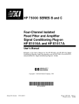
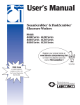
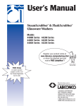
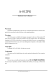
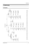
Service Manual
STAR T3/T3R UPS
6kVA~10kVA 220VAC
www.allis.com.tw
ST3 6-10kVA Service Manual Rev.1
Content
1. PSDR Introduction............................................................................................................................ 1
1.1 6/10 kVA PSDR-Right side ...................................................................................................... 1
1.2 6/10 kVA PSDR-Left side ........................................................................................................ 1
2. Fault and Warning ............................................................................................................................ 2
3. Troubleshooting................................................................................................................................ 3
3.1 Quick Start............................................................................................................................... 3
3.2 PFC Analysis:.......................................................................................................................... 4
3.3 Boost Analysis......................................................................................................................... 5
3.4 Inverter Analysis...................................................................................................................... 7
3.5 Charger Module Analysis ........................................................................................................ 8
3.6 PFC / Boost / Inverter IGBT Driver Module Analysis ............................................................. 10
4. Final testing.................................................................................................................................... 11
ST3 6-10kVA Service Manual Rev.1
1. PSDR Introduction
1.1 6/10 kVA PSDR-Right side
c
1.2 6/10 kVA PSDR-Left side
d
f e
e
f
d
1. Bypass Mosfet Driver
2. Inverter IGBT Driver Module
3. Boost IGBT Driver Module
4. PFC IGBT Driver Module
Allis Electric
Page 1 of total 13
September 2006
ST3 6-10kVA Service Manual Rev.1
2. Fault and Warning
LCD & LED Status /
Audible Alarms
AC: OK
BATT: OK
TEMP Fail
Fault
Warning
Normal
y
y
UPS in Bypass Mode.
The alarm beeps continuously.
AC: OK
BATT: OK
Inverter Fail
Fault
Warning
Normal
Possible Cause
1. Fan fail.
2. Temperature is
higher than
allowed operation
temperature.
1.
2.
3.
y
y
y
y
UPS in Bypass Mode.
Fault LED lights up and the
alarm beeps continuously.
AC: OK
BATT: LOW
Normal Mode
Fault
Warning
Normal
UPS in Normal Mode, but
battery capacity is low.
The alarm beeps once every
second for battery low.
AC: OK
BATT: OK
DC_BUS Fail
Fault
Warning
Normal
UPS stop working.
The alarm beeps continuously.
Allis Electric
1.
2.
Inverter circuit
failed.
Inverter driver
failed.
PFC circuit failed.
Replace the fan.
Reduce ambient
temperature or O/P load.
1. Replace the Inverter
components or driver.
2. Replace the PFC
components or driver.
1. Charger may
break down.
1.
Please replace charger
board.
1.
1.
Replace the Boost
components.
Replace the Inverter
components.
Replace the PFC
components.
Replace the BUS circuit
components.
2.
3.
4.
y
y
Action
Boost circuit
failed.
Inverter circuit
failed
PFC circuit failed
BUS circuit failed.
2.
3.
4.
Page 2 of total 12
September 2006
ST3 6-10kVA Service Manual Rev.1
3. Troubleshooting
3.1 Quick Start
For the 6 and 10kVA, both of the boards are the same size, only the some power components of
10kVA should be more than 6kVA.
Before any check of UPS, please check the components as listed in the following table. This action could help you find
problem quickly and make sure these components good or not first.
Possible Circuit Block
Coded Components
Description
Failure Mode
BAT FUSE
F303/F304
Fuse
Open
I/P FUSE (on PSDR)
F301/F302
Fuse
Open
PFC Correction
Q301, Q302
MOSFET
A-K Short or open
Push-Pull Boost
Q306, Q307,Q308, Q309, IGBT
D-S short or open
Q310, Q311
D302, D304, D306, D303, Power Diode
Short or open
D305, D307
D309, D311, D308, D310
Inverter
Q201, Q202, Q203, Q204 IGBT
C-E short or open
D201, D202, D203, D204, Power Diode
Short or open
D205
D210, D211, D212, D213
Charger module(standard)
IP SCR module
Q907, Q908
D901,D902,D903
Q909
Q3, Q4, Q5, Q6
IGBT
Power Diode
MOSFET
MOSFET
D-S short or open
Short or open
A-K Short or open
A-K short or open
If the fuse is open, replacing fuse only, DO NOT mean you have solved the problem. General
speaking, fuse open was caused by other failure of components; therefore, you must find the
real defective components and replace them, before restart the UPS.
Allis Electric
Page 3 of total 12
September 2006
ST3 6-10kVA Service Manual Rev.1
3. Troubleshooting
3.2 PFC Analysis:
In this section, some components you could check to see if failure occurs on PFC Correction circuit as shown below. Be
aware of F301, F302 fuse open indicates failure of this block. Please replace all faulty components before re-start the UPS.
6/10kVA-PFC-Right side
6/10kVA-PFC-Left side
Step
1
2
Checked components
F301, F302
Q301
Q302
(A, K)
(G, K)
Instrument
function
Ω
Ω
Ω
Reference
Value
0Ω
2.6 MΩ
10 Ω
Failure Mode
Open
Short or open
Short or open
Action ltem: If all above-stated components are replaced well and UPS still can’t work, change the PFC
IGBT driver module.
Allis Electric
Page 4 of total 12
September 2006
ST3 6-10kVA Service Manual Rev.1
3. Troubleshooting
3.3 Boost Analysis
6/10kVA-Boost-Right side
6/10kVA-Boost-Left side
Step
1
Checked components
Instrument
function
Q306~Q311 (E,C)
Ω
Reference
Value
800kΩ
Failure Mode
(G,E)
Ω
15.8kΩ
short or open
short
2
D308, D310, D309, D311
DIODE
0.35V
0V
3
D302, D304, D306, D303,
D305, D307
DIODE
12Ω
open
Allis Electric
Page 5 of total 12
September 2006
ST3 6-10kVA Service Manual Rev.1
4
Ω
10Ω
open
Ω
2.2Ω
open
6
R325, R331, R334, R342,
R337, R328
R390, R388, R389, R393,
R392, R391
F303, F304
Ω
0Ω
open
7
Q305
(A,K)
Ω
2.5MΩ
short
(G,K)
Ω
10Ω
short
5
Action ltem: If all above-stated components are replaced well and UPS still can’t be DC start, change Boost
IGBT Driver Module.
Allis Electric
Page 6 of total 12
September 2006
ST3 6-10kVA Service Manual Rev.1
3. Troubleshooting
3.4 Inverter Analysis
6/10kVA-Inverter-Right side
6/10kVA-Inverter-Middle side
6/10kVA-Inverter-Left side
Step
Checked components
1
Q201,Q202,
Q203,Q204
(E,C)
(G,E)
2
3
4
5
D201,D202,D203,D204,D205
D210,D211,D212,D213
R201,R202,R208,R209
R203,R204,R210,R211
Instrument
function
Ω
Ω
Reference
Failure Mode
Value
100kΩ
Short
23.5kΩ
Short or Open
Diode
Diode
Ω
Ω
0.36V
46Ω
10Ω
36Ω
0V
Open
Open
Open
Action ltem:Make sure the DC fuses with same rating as original ones for replacement. Otherwise,
unpredictable danger might happen.
Allis Electric
Page 7 of total 12
September 2006
ST3 6-10kVA Service Manual Rev.1
3. Troubleshooting
3.5 Charger Module Analysis
6/10 kVA-Charger Module- Long back-up type
Step
Checked components
Instrument
function
1
F1
Ω
2
Q301
Q105
(E,C)
3
4
D303
R315
5
R319
6
7
D106
R112,R159
Ω
8
Q04
(A,K)
(G,E)
DIODE
Ω
Ω
DIODE
(G,K)
9
R320,R321,R322,R340,R339, Ω
R341
Allis Electric
Reference
Failure Mode
Value
open
0Ω
Ω
Ω
≈0.4V
10Ω
1kΩ
≈0.4V
10Ω
Ω
Ω
≈0.5/6 Ω
≈1MΩ
10kΩ
0V
open
open
0V
open
≈1MΩ
≈12Ω
open
Page 8 of total 12
September 2006
ST3 6-10kVA Service Manual Rev.1
6/10 kVA- Charger Module- Standard type
Step
1
2
3
4
Checked components
F901,F902,F903,
F904,F905,F906,
Q907,Q908,
D901,D902,
D903
Q909
Instrument
function
Ω
(S, D)
(G, S)
DIODE
(A, K)
(G, K)
Allis Electric
Reference
Failure Mode
Value
open
0Ω
Ω
Ω
≈1.7MΩ
Ω
Ω
≈20MΩ
≈0.4V
32Ω
0V
≈42Ω
Page 9 of total 12
September 2006
ST3 6-10kVA Service Manual Rev.1
3. Troubleshooting
3.6 PFC / Boost / Inverter IGBT Driver Module Analysis
6/10kVA-Boost-Right side
6/10kVA-Boost-Left side
Step
1(RED)
2(BLUE)
Allis Electric
Checked components
Instrument
function
ZD201
Q201,Q202
V
V
R203,R205
D201
Q01
Ω
V
V
Reference
Value
0.7V
VBE=0625V,
VBC=0.625V
10Ω
0.580V
VSD=0.5V
VSG=2.225V
Failure Mode
0V
0V
Open
0V
0V
Page 10 of total 13
September 2006
ST3 6-10kVA Service Manual Rev.1
4. Final testing
After you have replaced all defective components on power stage (PSDR), please follow the steps as below.
Step 1. Install the PSDR board into UPS unit, but DO NOT connect with “Battery” and “Input source”.
- Before go to step 2, make sure all of the cable should be connected the right position.
- Do not connect with AC power source yet.
Step 2. Supply DC voltage (270Vdc/3 Amp (limited current) for 6/10kVA) with DC power supply via BAT(+) and BAT(-).
Press the switch on front panel for more than 3 seconds, you will see "current limit" for a short time on the DC power
supply for about only 2 seconds, then UPS should be DC start (If UPS does not start successfully, and LCD display off,
replace the above procedure). If UPS fails to start up for several times or DC power supply is on current-limit state
continuously, there must be some defective components exist. Please follow the section 3 trouble shooting to check again.
Allis Electric
Page 11 of total 13
September 2006
ST3 6-10kVA Service Manual Rev.1
4. Final testing
Step 3. If the UPS re-start normally, check the DC_BUS and output voltage.
- For 6/10kVA, DC_BUS: +340~350 and -340~350VDC, deviation between negative and positive voltage should be within
10VDC. Output Voltage: 220/230/240 +/-2%
DC-BUS Voltage: Positive
®
DC_BUS: + 340~350VDC
_
DC-BUS Voltage: Negative
_
DC_BUS: - 340~350VDC
®
Allis Electric
Page 12 of total 12
September 2006
ST3 6-10kVA Service Manual Rev.1
4. Final testing
Output Voltage
Output Voltage: 220/230/240 +/-2%
Step 5. Connect with AC power source, then follow the step3 and step4 to check the DC_BUS and output voltage again.
Also, the charger voltage need to be confirmed, the charger voltage should be 274VDC +/-1%. If UPS fails to start up for
several times, there must be some defective components exist. Please follow section 3 trouble shooting to check again.
_
Charger Voltage: 274VDC +/-1%
®
Allis Electric
Page 13 of total 13
September 2006