1
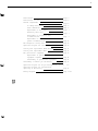
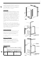
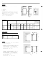
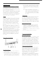
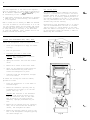
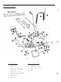
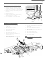
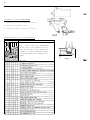
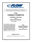
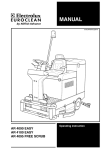
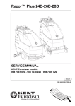
etic
1
1
United States
SALES OFFICES
DOMETIC SALES CORP.
2320 Industrial Pkwy.
Elkhart, IN 46515
Phone 219-295-5228
DOMETIC SALES CORP.
14441 Bonelli St.
City of industry, CA 91746
Phone 818-968-9431
DOMETIC SALES CORP.
1625-A Rock Mountain Blvd.
Stone Mountain, GA 30083
Phone 404-493-6214
DOMETIC SALES CORP.
7895 SW. Hunziker Rd.
Portland, OR 97223
Phone 503-620-9510
DOMETIC SALES CORP.
2920 Avenue “E” East
Alington, TX 76011
- P h o n e 817-277-72 1
East Oak Ridge Dr.
Rt. 9, Box I7 A
Hagerstown, MD 21740
Phone 301-797-0826
1000 01
”
DOMETIC SALES CORP.
RM360
RM460
RM660
RM760
Canada
Euroclean Canada Inc.
Dometic Recreation Division
866 Langs Drive
Cambridge, Ontario
N3H 2N7 Canada
(519) 653-8880
REFRIGERATOR
,
SERVICE MANUAL
-1
Edition
RM360
RM460
RM660
RM760
1
Publication No.
5415-E I Service
DSC #650
Diagnostic Service Manuals
2
Installation
page 3
Instructions for use
page 6
Cabinet adjustments
page 8
To change door panel
page 8
Panel dimensions
page 8
Replacement of door gasket
page 9
Reversing outer door
page 9
Replacement of evaporator door
on RM360/460/660
page 9
Replacement of evaporator door
gasket on RM360/460/660
page 10
The absorption cooling unit
page 10
Operation analysis for cooling unit
page 10
Cooling unit replacement RM360/460/660
page 11
Cooling unit replacement RM760
page 12
The gas/electric equipment
page 13
Replacement of gas/electric
equipment complete
page 14
Disassembly of gas/electric equipment
page 14
Disassembly of burner jet and burner
page 15
Operation analysis for LP gas refrigerators - p a g e
15
Operation analysis for refrigerators
operating on electricity
page 16
Wiring diagrams
page 17-18
3
INSTALLATION
ELECTRICAL
GENERAL
115 Volts A C
INSTRUCTIONS
The refrigerators outlined hereon have been design certified under ANS Z 21.19 Refrigerators
by the American Gas Association for installation
in a mobile home or recreational vehicle and are
approved by the Canadian Gas Association. The
certifications are, however, contingent on the
installation being made in accordance with the
following instructions.
CONNECTION
The refrigerator is equipped with a three
prong (grounded) plug for protection against
shock hazard and should be plugged directly
into a properly grounded three prong receptacle. Do not cut or remove the grounding
prong from this plug. The cord should be
routed to avoid coming in contact with the
burner cover, flue cover or other hot components.
The installation must in the USA conform with:
12 Volts VDC optional for certain models
1. National Fuel Gas Code Z223.1-1974
2. Mobile Homes A119.1-1972
3. Recreational Vehicles A119.2-1970
4. Any applicable local code
On "Tri-Pover" units there is an additional
terminal block marked "12 V". The refrigerator must be connected to the battery circuit
with two wires of adequate capacity to avoid
voltage drop. The wire gage should be chosen
with consideration to the wire length in
accordance with the following tabel: The 12 V
circuit must be fused with an appropriate
fuse.
In Canada
TABLE
1. Standard CGA lO.l/CSA 2240.4 gas equipped
mobile housing and recreational vehicles
2. Standard CSA Z240.6.1 electrical requirements
for mobile housing
3. Standard CSA Z240.6.2/C22.2 No 148 electrical
requirements for recreational vehicles
Maximum two conductor wire length for different
AWG numbers.
The unit must be electrically grounded in accordance with the National Electrical Code ANSI, CI1968, when installed if an external alternating
current electrical source is utilized.
Maximum two conductor wire length in feet
AWG
RM360
120w
RM460
135w
RM660
175w
RM760
250W
14
12
10
8
6
4
10
17
27
43
69
110
9
15
25
40
64
102
7
12
19
31
49
79
5
8
13
22
34
55
Ventilation
The installation shall be made in such a manner
as to separate the combustion system from the
living space of the mobile home or recreational
vehicle. Openings for air supply or for venting
of combustion products shall have a minimum dimension of not less than l/4 inch.
Proper installation requires one lower fresh air
intake and one upper exhaust vent. The ventilation kits shown in this instruction booklet have
been certified for use with the refrigerator models listed in the tables. The ventilation kits
must be installed and used without modification.
An opening towards the outside at floor level in
the refrigerator compartment must be provided for
ventilation of heavier-than-air fuel gases. The
lower vent of the recommended kits is provided
with proper size opening.
For ready serviceability of the burner and control manifold parts of the refrigerator the lower
side vent is fitted with a lift-out panel which
provides an adequate access opening.
Do not use the body or chassis of the
vehicle as a substitute for either of the two
conductors. No other electrical equipment
or lighting should be connected to the refrigerator circuit. The refrigerator will draw
from l0-21 Amps at 12 Volt depending on model.
CAUTION
Do not operate the refrigerator on 12 Volt when
the vehicle is parked. You will run out of
battery in a rather short time.
GAS CONNECTION
Hook-up to the gas supply line is accomplished at the manual gas valve, which is furnished with a 3/8" SAE (UNF 5/8"-18) male flare
connection. All completed connections should
be checked for leaks with soapy water.
The gas supply system must incorporate a
pressure regulator to maintain a supply pressure of not more than 11 inches water gage.
F i g . 1
m
4
If possible the installation of a 12 Volt
operated refrigerator should be completed with
a relay mounted either in the car or in the
recreational vehicle (see Fig. 1). This relay
will automatically cut out the refrigerator
when the car motor is stopped.
SPECIAL HINTS
The refrigerator must be installed in a substantial enclosure and must be level. A spirit
level is supplied with each refrigerator and
by placing it in the freezer compartment one
can level the refrigerator both ways front to
back and side to side. When installing the refrigerator in the enclosure care should be
taken to ensure a complete sealing between the
front frame of the refrigerator and the top,
sides and bottom of the enclosure. For this
purpose a length of sealing strip is applied
to the rear surfaces of the front frame.
A sealing strip should also be applied to the
foremost floor of the enclosure as shown in
Fig. 2.
/
l-l _.
Be careful not to damage the sealing strip
applied to the floor of the enclosure when the
refrigerator must be blocked. The heat produced
at the rear of the refrigerator will otherwise
become trapped in this space making the top of
the refrigerator hot and reducing the efficiency of the refrigerator.
Minimum w
ventilation
height
CERTIFIED INSTALLATION
Certified installations require one roof vent
and one lower side vent or as optional one
upper vent and one lower side vent. The two
alternatives are provided for by using the
different kits listed in the Appendix.
For further information contact your dealer
or distributor.
Fig.3
METHODS OF INSTALLATION
The methods of installation are shown in
figures 3 and 4. It is essential that all
maximum or minimum dimensions are strictly
maintained as the performance of the refrigerator is dependent on an adequate flow of
air over the rear of the refrigerator.
area 5"x 18”
Ventilation
VENTILATION HEIGHTS
Refrigerator
RM360
RM460
RM660
RM760
:.jiiGj
Minimum ventilation heights in inches
37
31
34
42
56
5
CLEARANCES
Minimum clearances in inches to combustible
materials are:
G:
K:
L:
M:
Top
Side
Bottom
Rear
0
0
0
1
Clearance M between the rear-most part of the
refrigerator and the wall behind the refrigerator.
Clearance N on top of the condenser is related
to the minimum ventilation height.
See Fig. 5 and examples below.
Fig.5
MEASUREMENTS
Height
A
RM360
RM460
RM660
RM760
Recess
dimensions
Installation
dimensions
Refrigerator Overall
dimensions
model
Width
B
Depth
C
Height
h
21 11/16
6 22 1/16 29 9/16
30 3/8
24 11/16
6 32 1/8
32 15/16
6 23
24 11/16
6 40
40 13/16
6 23
23
24 11/16 51 3/16
52
Width
W
20
21
21
21
Distance
between top
of condenser
to top of
refrigerator
1/4
9/16
9/16
9/16
Depth
d
Height Width
W
H
20
22
22
22
29
32
40
51
3/16
6
3/4
3/4
3/4
3/4
5/16
6
3/16
6
3/8
20
21
21
21
1/2
13/16
6
13/16
6
13/16
6
Storane volumes
Refrigerator Total storage volume in cu ft
model
RM360
RM460
RM660
RM760
3.0
3.9
5.1
6.0
EXAMPLES
The clearance N for the RM360 model is derived
atin the following way:
A. Installation with upper and lower side vents.
N=Minimum ventilation height 37 minus installation height 29 9/16 plus distance
between condenser top and refrigerator top
1 l/4
N=37-29 9/16+1 l/4=8 11/16.
B. Installation with roof vent and lower side
vent.
N=Minimum ventilation height 31 minus installation height 29 9/16 plus distance
between condenser top and refrigerator top
1 l/4 plus distance between roof surface
and roof vent cap 5 l/4.
N=31-29 9/16+1 l/4+5 l/4=7 15/16.
Fig.6
Depth
D
21
23
23
23
3/16
3/4
3/4
3/4
e
1 1/4
1 1/4
1 1/4
1/8
6
INSTRUCTIONS FOR USE
INSTALLATION OF THE REFRIGERATOR IN A VEHICLE
The refrigerator must be installed on a solid
floor and must be level. With the vehicle carefully leveled the refrigerator should level both
ways in the freezer compartment.
Free air circulation over the fins of the cooling
unit is essential. Clearances around the refrigerator should be in accordance with the label
attached to the rear plate of the refrigerator.
In case detailed instructions on the installation
and connection to the gas supply are required,
contact your dealer or distributor.
Leveling
In the boiler ammonia vapor is distilled from an
ammonia-water mixture and carried to the finned
condenser, where it liquifies. The liquid flows
to the evaporator, where it creates cold by
evaporating into a circulating flow of hydrogen
gas. If the evaporator coil is not level the
liquid readily accumulates, forming pockets
w h i c h can impair the gas circulation or even
block it, in which case, of course, the cooling
will stop.
When the recreational vehicle is stationary it
must be leveled to be comfortable to live in. If
the refrigerator is properly installed, i e the
freezer shelf parallel to the floor, the refrigerator will then also perform well.
A bubble level should be placed on the freezer
shelf. When the vehicle is on tow, the continuous
rolling and pitching movement will not affect
the refrigerator as long as the movement passes
either side of level, but when the trailer is
temporarily parked this sensitivity of the refrigerator should be remembered. So, once more,
before you start the refrigerator, make sure
it is level.
4. After the gas is lit keep the button C pushed
for 10 seconds. Release the button and check
through the reflector that the burner flame
stays burning. If not repeat the lighting procedure.
NOTE: After a replacement of the gas container or a long shut off period the gas
line is likely to be filled with air. In
such a case the lighting procedure has
to be repeated until the air is pushed
out of the line and the gas has reached
the burner.
Flame Blow Out
If trouble is encountered with the flame blowing
out under specially windy conditions, try to
avoid the wind blowing against the wall where
vent outlets are located. If the trouble persists,
set the thermostat to MAX. This later measure
can of course only be temporary such as when the
vehicle is on tow, for after a day or so at this
setting the foodstuffs in the cabinet will freeze.
Electric Operation (Fig. 7)
1. Check that the attachment plug is correctly
connected to the mains supply. When the refrigerator is equipped also for 12 Volts D C
operation the low voltage connection is made
at the marked terminals at the rear of the refrigerator.
2. Turn the knob A to desired position for electric
operation.
3. Turn the thermostat knob B to setting 4.
HOW TO USE THE REFRIGERATOR
Food Storage Compartment
HOW TO START THE REFRIGERATOR.
The food storage compartment is completely closed
and unventilated, which is necessary to maintain
the required low temperature for food storage.
Consequently foods having a strong odor or liable
to absorb odors should be covered. Vegetables,
salads etc. should be covered to retain their
crispness. The coldest positions in the refrigerators are underneath the cooling evaporator and
at the bottom of the refrigerator, and the least
cold positions are on the upper door shelves. This
should be considered when different types of food
are placed in the refrigerator.
Frozen Food Storage Compartment
Fig.7
Gas Operation(Fig. 7)
1. To start
position
2. Turn the
3. Push the
D of the
repeated
This can
the refrigerator turn the knob A to
"GAS".
thermostat knob B to setting 4.
button C to stop and push the button
piezo igniter. The pushing has to be
until the gas is lit at the burner.
be observed through the reflector E.
The ice trays should be placed in direct contact
with the freezer shelf for fastest ice making.
Quick frozen soft fruits and ice cream should be
placed in the coldest part of the compartment,
which is at the bottom of the aluminum liner or,
in models with a shelf, on this or just below it.
Frozen vegetables, on the other hand, may be
stored in any part of the compartment.
The compartment is not designed for the deep or
quick freezing of foodstuffs. Meat or fish foods,
whether raw or prepared, and provided they are
precooled in the refrigerator, can however, also
7
be stored in the frozen food storage compartment.
They can then be stored about three times as
long as in the fresh food storage compartment.
To prevent drying out, keep food in covered
dishes, in plastic bags or wrapped in aluminum
foil.
CAUTION
Do not store explosive substances in the refrigerator, such as cigarette lighter gas,
petrol, ether or the like.
of weeks, it should be emptied and cleaned and
the door left ajar. The ice trays should also
be dried and kept outside the cabinet.
Cleaning
To clean the interior lining of the refrigerator
use lukewarm weak soda solution. The evaporator,
ice trays and shelves must, however, be cleaned
with warm water only. Never use strong chemicals
or abrasives to clean these parts or the protective surface will be spoiled. It is important
always to keep the refrigerator clean.
Ice Making
Periodic maintenance
Ice cubes can be made in the ice trays which
should be filled with water to within l/4"
(5 nun) from the top. To release the ice cubes
seize the tray with both hands and twist the
tray. Cubes not required should preferably
be replaced in the tray. Refill the tray with
water and replace the tray on the freezer
shelf.
Ice making is accelerated if the thermostat
knob is turned to setting "MAX". It is a good
idea to do this a few hours before an anticipated need for ice but be sure to turn the
knob back to normal setting when the ice is
formed or the foodstuffs in the cabinet may
become frozen hard.
Defrosting
Some refrigerator models are equipped with an
automatic defrosting device incorporated with
the cooling unit. This device makes a quick
defrost of the finned evaporator section about
once a day without affecting the frozen food
storage compartment or the frozen foods contained
in. When the frozen food storage 'compartment is
covered with frost the refrigerator must be shut
down temporarily till the frost is melted. Before
the refrigerator is restarted the compartment
should be dried, the ice trays washed and refilled with fresh water.
When the frost on the finned evaporator section
has melted, water will be collected in the drip
tray. The drip tray should be emptied at regular
intervals.
Some refrigerators without the automatic defrosting device should be defrosted regularly'
by turning off the refrigerator. Empty the refrigerator leaving the drip tray under the finned
evaporator and the cabinet and freezer doors
open. If desired, defrosting may be speeded up
by filling the ice tray with hot water and
placing it in the freezer.
When all frost is melted, empty the drip tray and
dry the interior of the refrigerator with a
clean cloth.
Replace the drip tray and ice tray, replace all
food stuffs and set the thermostat to "MAX" for
a few hours. Then reset the thermostat knob to
its normal position.
To Shut Down the Refrigerator
To shut down the refrigerator temporarily set
the thermostat to off and turn off the gas tap.
If the cabinet is not in operation over a period
NOTE: Before working on the refrigerator, make
sure that 110 V A. C. and optional 12 VD.C.
leads are disconnected.
Once or twice a year depending on use, it is
necessary to clean and adjust the burner assembly.
Proceed as follows:
1. Loosen screw and remove cover plate for burner
housing.
2. Disconnect lighter cable from the electrode.
3. Loosen burner fixing screw and withdraw burner.
4. Clean burner tube with a brush. Blow with
compressed air.
5. Screw off jet and clean with alcohol. Blow
with compressed air. Never use a needle or
similar.
6. Clean flue baffle and flue.
7. Clean the cooling unit and the floor under the
refrigerator.
8. Reassemble.
9. The entire gas installation should be checked
for leaks. Test all pipe connections with
soapy water, not with an open flame.
a
CABINET ADJUSTMENTS
To change door panel
The refrigerator is normally delivered without door
panel(s). Before starting the mounting work check
that the panel dimensions are in compliance with
those given in the table and read the instructions
through. When mounting the panel, proceed as follows:
1. Remove the top decoration strip (2) with its
two screws (1).
2. Insert one of the vertical edges of the p anel
into the groove of the door frame (3).
3. Bend the panel gently so that the free side of
the panel can be slipped into the corresponding
groove of the door frame (4).
4. Push the panel downwards so that the lower horizontal edge of the panel is fitted into the
bottom groove (5).
5. Between the upper edge of the panel and the door
frame there is now a gap which should be covered
by the decoration strip.
6. Put the strip across the door so that the gap
is covered and push it upwards (6).
The tabs on the inside of the strip should fit
in behind the flange of the door frame. Secure
the decoration strip by means of the two screws (1).
Panel dimensions
Thickness max. 5/32"
Height
Min.
Width
Max.
Min.
516,5
20 11/32"
513,5
mm
20 7/32"inch
550,5
21 11/16"
547,5
21 9,16":ch
550,5
21 11/16"
547,5
mm
21 9/16"inch
285
288
11 11/32" 11 7/32"
550,5
21 11/16"
547,5
mm
21 9/16"inch
798
801
31 17/32" 31 13/32"
550,5
21 11/16"
547,5
mm
21 9/16"inch
Type
Max.
RM 360
636
25"
RM 460
676
679
26 23/32" 26 19/32"
RM 660
879
34 5/8"
RM 760
upper
RM 760
lower
633
24 7/8"
876
34 l/2"
Fig.8
9
Replacement of door gasket (Fig. 9)
1. Pull the old gasket out from the door frame.
2. Make sure that no gasket parts are left in
the groove.
3. Beginning in one of the corners, fit the new
gasket by pressing it into the groove.
Fig.9
Reversing outer door (Fig. 10)
1. Remove the plastic cover (1) by loosening the
screws (2) underneath.
2. Remove the upper hinge pin (3).
3. Remove the door and move the lower hinge pin (4)
to the other side.
4. Fit the door and press the upper hinge pin
(3) into the adequate hole.
For two-door refrigerators the middle hinge and
the travel latch should change position.
Fig.10
Replacement of evaporator door on RM360,
RM460, RM660 (Fig. 11 and 12)
1. Pry the spring housings (B) away from the li-
ning so that it snaps out and turn the spring
housing downwards 180'.
2. Push the carrier (A) inwards by means of a
blunt mandrel or pin and remove the shutter.
3. Mount the new shutter in close position first
on one side, making sure that the cross slots
engage in the cross on the hinge plate (C).
4. Press the carrier on the opposite side so that
the hinge plate on the shutter can be pushed
over it. See that the crosses engage.
5. Turn the spring housing round and up until the
small tag (D) snaps into the slot into the
lining.
Fig.11
Fig.12
Replacement of evaporator door gasket on RM360,
RM460, RM660
1. Remove the door as previously described.
2. Unscrew the hinge plates (A fig. 13).
3. Put shutter on a flat surface with the sealing
gasket up.
4. Pry the shutter front away from the inner
pan by means of a screwdriver.
CAUTION: It is of great importance that the
screw driwer is applied in front of one of
the plastic tongues (B fig. 13) which hold
the inner panel and the shutter front together.
5. Replace the sealing gasket round the inner panel and snap the inner panel with
sealing gasket into the shutter front
until the tongues snap in position.
6. Mount the shutter as described above.
Fig.13
THE ABSORPTION COOLING UNIT
Sealed system construction
The sealed system of the absorption refrigerator
is constructed of welded steel piping which contains the refrigerant charge. The charge consists
of ammonia, hydrogen and water. There are no moving parts associated with the absorption system.
If an excessive vaporizing of the ammonia within the
boiler occurs due to the reasons above, the liquid
mixture in the boiler becomes very weak and the pump
will cease to operate, which means that the circulation of liquid stops with the result that the evaporator inside the cabinet ceases to produce cooling.
When servicing an absorption system refrigerator,
do not puncture or break the piping. Should a
break occur and ammonia contact the skin, wash the
affected area immediately with clear water. Do not
attempt to open the valve on the absorber vessel.
The valve is covered with a plastic can and should
never be removed.
Such a blockage of the unit in the liquid circuit
ist most usually made evident by signs of overheating on the vapour pipe leading from the boiler to
the condenser, the paint on this pipe being blistered and the metal becoming discouloured.
OPERATION ANALYSIS FOR COOLING UNIT
It is obviously important that all external factors affecting the unit should be checked properly
before a unit is condemned as faulty and that emphasis has been placed upon the necessity for correct
installation, upright refrigerator, correct heat input, baffle position, etc. Check the size and the
wattage of the electric heater and make sure that
the heater element is inserted to its full length
in its pocket. If the electric heater is only partly inserted, the heat distribution will be incorrect,
causing an excessive vaporizing of the ammonia within
the boiler when operating on electricity. The same
symptom can show up with too much or too little
heat input either on electric or on gas operation
and also if the refrigerator had been operating in
an off-level position or with inadequate ventilation.
To remedy this fault it is recommended to remove the
unit or refrigerator complete whenever possible and
to allow sufficient time to- cool down the unit. Turn
the unit or refrigerator upside down several times,
so that the liquid in the absorber vessel can be
mixed with the liquid in the boiler. This procedure
will restore the liquid balance to the unit.
The temperatures on various parts of a unit vary
continuously when it is operating on thermostatic
control and it is impossible to base a judgment on
the symptoms given unless the refrigerator has been
operating continuously on fully correct heat input
for at least 5 hours, and preferably 12 hours, prior
to examination. In many cases this can be arranged
by a telephone call to the customer, asking him to
switch the thermostat to "MAX" on the day before the
inspection call. If after 12 hours' operation on
"MAX" the performance is satisfactory, the unit is
not at fault unless the complaint is one of varying
or intermittent performance. In this connection
11
the room temperature at the time of the complaint
must be considered, as a unit which is satisfactory
at an ambient temperature ofo650F (+18OC) may not
be satisfactory at 95 F (+35 C).
In cases where satisfactory performance is obtained
"MAX" but not on other settings, the thermostat
is to be suspected.
When a normal unit is working on "MAX" the absorber
coil will be warmer at the bottom than it is at the
top. The absorber vessel will be warmer. The vapour
cooling pipe from the boiler to the condenser will
be warm, bearably to the hand, at the bend where
it joins the condenser, with a gradual rise in temperature towards the boiler end.
Unit filling valve
The needle valve used for admitting the filling
charge to a cooling unit is fitted to the unit's
absorber vessel and is covered by an aluminium or
plastic cap. It is strictly applied provision of
the warranty extended on the unit to the customer,
that any interference with the filling valve will
automatically void the warranty.
Unsatisfactory unit performance due to an ammonia
leak can be determined in the case of a visible
leak by traces of a yellow deposit at the point
where the ammonia is escaping. If there is a leak
on the evaporator inside the cabinet, a smell of
ammonia may bee noticeable.
COOLING UNIT REPLACEMENT RM360, RM460, RM660
Remove the refrigerator from its recess as follows
1.
Check that refrigerator is empty and remove
ice tray.
2.
Turn off gas bottle.
3.
Disconnect gas line to inlet valve
CAUTION: Use a backup wrench to prevent
undue rotation.
4.
Unplug the electric line from the trailer
outlet.
5.
Remove the 4 screws in rear front frame.
6.
Check for any additional screws which the
vehicle manufacturer may have used to
fasten the refrigerator in place.
7.
Carefully slide the refrigerator straight
out of its recess.
Fig.14
- 6
To remove the cooling unit from the cabinet,
proceed as follows:
1.
Place the refrigerator on a work bench of
suitable height.
2.
Remove the thermostat capillary tube by
loosening the two screws (1) on the evaporator fins (fig. 14).
CAUTION: The locations of the thermostat
capillary tube should be noted at this
time for relocation later on. The tubes
must be placed in the right position,
otherwise, improper performance may result.
3.
Remove the two sealing plugs for capillary
tube, one on the back and one inside the
cabinet, and straighten the tubes.
4.
Remove the capillary tubes by going to the
back of the refrigerator and gently pulling
the tubes straight out.
Fig.15
12
5.
Remove the screws (2) in fig. 14 and take away the
evaporator fin. Remove the screws (3).
6.
Remove the connection block (4) cover (Fig. 15) and disconnect the electrical wires for the heaters.
7.
Remove the grounding screw (5).(Fig. 15).
8.
Remove the flue and the flue baffle.
9.
Remove the screws (6), holding the absorption unit
onto the back of the cabinet.
10.
Disconnect the burner case by turning the lever
(7) as shown in the picture.
11.
Carefully bend absorption unit out of cabinet
(Use a crowbar or similar and a wooden piece as
protection when doing this).
12.
To replace absorption unit, reverse above procedure.
8
9
CAUTION:
1.
Be sure to apply sealing permagum (8) on the
unit mounting plate (Fig. 16).
2.
Be sure to apply proper amount of "Thermal Mastic" on the evaporator coil (9).
3.
When fitting the evaporator fin be sure to tighten
the screws properly in order to obtain a perfect
contact between the evaporator coil and evaporator flange, otherwise improper cabinet performance
may result.
Fig.16
Fig.17
COOLING UNIT REPLACEMENT RM760
The following steps are different from the models RM360,
RM460 and RM660.
1.
The screws (1) in the freezer should be removed (Fig. 18)
2.
The capillary tube should carefully be pulled
out from the tube (2).(Fig. 19).
3.
When bending the cooling unit out, place the crowbar
or similar as well as the wooden protection as shown
in the picture.
Fig.18
Fig.19
13
THE GAS/ELECTRIC EQUIPMENT
Fig.20
Gas equipment parts
1.
2.
3.
4.
5.
6.
7.
8.
9.
10.
11.
12.
13.
Burner tube
Burner, housing
Jet
Feeler point thermocouple)
Flame failure safety device
Bypass screw
Gas/Electric thermostat
Pressure test gage connection
Capillary tube for thermostat
Shut-off value
Piezo igniter
Firing tip
Flue baffle
Electric equipment parts
14.
15.
16.
17.
18.
19.
Flexible cord
Change-over switch
Terminal block, 12 VDC
Fuse
Relay
Heater
14
Replacement of gas/electric equipment complete
1.
Remove the covers by removing the screws (1).
2.
Disconnect the heater cords at the terminal
blocks (note the locations for later relocation).
3.
Remove the capillary tube carefully from the
evaporator.
4.
Remove the screws (2).
5.
Release the burner housing from the flue by
turning the lever (3) as shown.
6.
Pull the equipment out from the cabinet.
1.
1
115v
220v
240v
_12V
ZI
Fig.21
Disassembly of gas electric/equipment
1.
Press the plastic latch (leftwards
in Fig. 22).
8.
Press the retaining spring for release of
thermocouple.
2.
Pull the relay out (if any).
9.
Pull out the thermocouple leftwards.
3.
Snap off the fuse holder.
4.
Press the spring.
5.
Pull the shut-off valve out.
6.
Press the gas/electric thermostat leftwards and lift it out.
7.
Unscrew the thermocouple from the flame
failure safety device.
2
0
10.
Pull the flame failure safety device left
and lift it out.
11.
Pull off the ignition cord.
12.
Snap off the retaining spring.
13.
Pull out the igniter.
NOTE:
-
When assembling, always use new
for the joints.
Fig.22
O-rings
15
DISASSEMBLY OF BURNER JET AND BURNER
removing the screw (1).
1.
Remove the cover by
2.
Unscrew the
3.
Remove the burner by removing the screw (3)
burner jet (2).
OPERATION ANALYSIS FOR LP GAS REFRIGERATORS
S Y M P T O M
CAUSE
P
z
:
48
u
2:: 2
c .rl
c .z : ‘;: S
;:
8”
”
c .; l.l MZ
T1z
8 8
8
c)
5
z
*
0)
‘d 2
g j $ .j
: L
2 .rl&W
.rlz g
MW 4.l z u ti
‘;: ‘C :
;: : : z
?”
diz$LZ80a
x
Note: It will be noted in this tabulation that
several causes can be responsible for the one
effect. The real cause or causes should be determined by a process of elimination, investigation each possible cause. proceeding to the
bottom.
Fig.24
Gas leaks
16
OPERATION ANALYSIS FOR REFRIGERATORS OPERATING ON ELECTRICITY
r S Y M P- T-O M-
C A U S E
272
2
5
20
Note: It will be noted in this tabulation that
a
4-l
rl
5
2
G
.rl
0”u 4-l“d .di ! *rlls -G”
w
z g 2u .d4
zlL! z .rls % “d
E 5cc G 2&J .dt.4
.?I
u ‘;1 it
v-4
ICI
8
0’
”
0
0
d d 2
x X
- X
X
- X
- - -X
X
X
- - - -X
- -X -X
X
X
- -X -X -X
- - -X -X
- - - - X
- - -X -X
- -X -X
-X - -
-iz
-
X
X
-
X
-
-0”
-X
-X
-X
-
several causes can be responsible for the one
effect. The real cause or causes should be determined by a process of elimination, investigating
each possible cause, starting at the top of the
tabulation and proceeding to the bottom.
Not adequate ventilation
Refrigerating unit not level
Heater faulty,wrong voltage or type
Voltage not constant
Electric connections loose
Heater not inserted correctly in its pocket
Improper food storage
The thermostat incorrectly used
Improper storage of liquids and moist foods
Leaky cabinet seals
Infrequent cleaning of food compartment
Refrigerator shut off with closed door
Unwrapped odorous food
Incomplete contact of thermostat capillary tube
Lost thermostat charge
Failed refrigerating unit
Room temperature too low
17
12VOLTS DC
200 7 3 9 0
12VOLTS DC
N
L
115 VOLTS AC
THERMOS TAT
0 JUNCTION BLOCK
0 TERMINAL BLOCK
@ GREEN
@ GREEN/YELLOW
Fig.25
Wiring Diagram for Product No. 926 63 01
RM760
115VOLTS A C
Fig.26
Wiring Diagram for Product No. 926 63 02
RM760
18
20075871
115VOLTS A C
@ SWITCH
@I THERMOS TAT
8 JHEyTIRm B L O C K
@ WHITE
@ BLACK
@ GREEN
Fig.27
W i r i n g D i a g r a m f o r Product No. 926 69 01, 926 70 01, 926 71 01
RM360
RM460
RM660
-I
115 VOLTS AC
m
@ SWITCH
@I T H E R M O S T A T
0 JUNCTION BLOCK
@ HEATER
e> TERMINAL BLOCK
8 FUSE
@ HEATER
- - N_
l
Lr-7
I
8,
6 BLACK
@j GREEN
@ GREEN/YEL LO W
Fig.28
I
zzz
Wiring Diagram for Product NO. 92 6 02, 92 7 02, 926 71 02
RM360
RM460
RM660