1
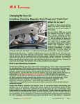
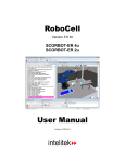
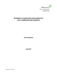
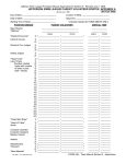
W A Technology
Replacing C6 Corvette Coolant
GM recommends the coolant be replaced
after 5 years or 150,000 miles whichever
occurs first. In a C6 it straight forward so
there is no reason not to do it on or before
that time.
With only 18,000 miles on the 2008 Vette but
4 ½ years it was time. The cooling system
has never been a problem and the
temperature always in the correct range.
Tools Required:
Other than a pair of pliers to help remove the drain plug (it’s plastic in plastic so
not difficult) and the proper jack there are no special tools - assuming you do not
need to use a “flush procedure” (see below.)
Is a Flush Needed?
The GM Service Manual recommends looking at the coolant and “If Normal in
Appearance” use what they call the “Filling Procedure.”
If it is “Discolored” the recommendation is to use a “Flush Procedure.”
Although both will be mentioned below, our fluid looked exactly like the new
coolant purchased so only the “Fill Procedure” was used. The first pictures in
the following outline will discuss the filling procedure used.
We followed this procedure and unlike what we normally have done and do in our
Street Rod, which is to fill a drained system with plain water, run the car with the
heater set on high, drain the remaining mixture of water and coolant then repeat
several times, we just followed GM’s recommendation. Since the coolant looked
brand new and there was hardly any residual in the Coolant Tank, we felt the
procedure was fine.
After the first photos and text covering the “Fill Procedure,” the GM “Flush
Procedure” is presented. NOTE: The Service Manual has a statement which
says IMPORTANT: Do not use a chemical flush! Therefore a flush procedure
does not mean you need to buy any flush product!
The flushing procedure just uses a water fill a number of times to get the full
system free from old coolant. It also recommends removing and cleaning the
Coolant Tank (also called a Surge Tank.) Several pictures will show how that is
done. This is a procedure we would normally use but it will require more new
coolant. We’ll explain, although the GM Service Manual does not and in fact is
incorrect!
Copyright by WA Technology, LLC
www.NetWelding.com
Page 1
Photo Sequence
The passenger side of Corvette will need
to be raised to gain easy access to the
radiator drain plug on the lower passenger
side of the radiator.
I recommend buying some jack pads. The
red aluminum one shown was purchased
as a set of 4 and fit into four slots in the
floor under the frame rail in locations that
can be used as a jacking points. They just
slip in the slot and with a ¼ twist stay in
place.
You do not have to lift very high for this
task as the drain plug can be accessed
from the front of the car by reaching in
with your hand.
The aluminum racing jack pictured has a
very low profile allowing plenty of room to
fit under the jack pad. Harbor Freight often
has these on sale for under $60.00. Place
a wheel chock behind the driver’s rear
wheel before jacking to prevent the car
from moving backward. Even though the
front passenger wheel need not be raised
more than about 4 inches and you do not
have to go under the car for any distance,
placing a 4 inch piece of wood under the
tire should provide the security needed.
Place about a 3 gallon shallow container
below the hole visible under the drain
plug. It will have to hold about 2 gallons
of drained coolant. Turn the drain plug
(yellow in sketch left) counterclockwise
about 3 or 4 turns. It may be possible to
start by hand but I used a pair of pliers
to help. The coolant will drain for about
20 minutes after removing the cap on
the coolant tank (see tank below.) Fully
remove drain plug and lubricate the “O”
ring at the end with clean coolant.
Insert and tighten the drain plug to
18 in-lbs. (slightly more than hand tight,
I snugged a little with pliers.)
Copyright by WA Technology, LLC
www.NetWelding.com
Page 2
Use a quality coolant like this one from
Prestone meeting GM Dex-Cool
specifications. Don’t consider anything
else! There was a $7.00 rebate offer
from Prestone and Walmart’s price was
$14.95 for the gallon. If following the
GM recommend ‘filling procedure” there
will be one gallon of 50/50 mixture left in
the engine. However, as mentioned, the
coolant removed looked new! When
filling I also used a gallon of distilled
water. Distilled water probably wasn’t
necessary but I did not want to trust tap
water and for $1/gallon the distilled
water is a safer choice!
Fill the Coolant Tank with a 50/50 mixture
of Coolant Concentrate and Water. I filled
alternately with equal measured amounts
of both from a small container.
1. After the first Tank fill to just
below the bottom of the fill tube
idle the engine for 4 minutes. I
shut off the engine after about 3
minutes and filled the now empty
Tank again.
You can buy as a 50/50 premix but it was
only $2/gallon less than the concentrate so
the $1/gallon of distilled water was the way
to go.
2. Run the engine this time for about
two minutes at 2000-2500 rpm.
Tank will empty. Although not
mentioned, I did this twice.
Follow the procedure outlined on the right.
3. GM recommends filling the empty
Coolant Tank with 1 quart of
coolant and monitoring. I used
somewhat more and found in the
morning it needed about 20 to 25
ounces more. Will monitor after
several cycles after driving and
cooling.
GM Fill Suggestion:
Note; If using the GM “Flush Procedure”
you will only be able to use Concentrated
Coolant. See last part of that procedure
for an explanation as to why.
Flush Procedure
1. Drain as in the “Fill Procedure”
and install drain plug hand tight.
2. Next remove the Coolant Tank
(green picture right) by first:
a) Relieve the tension on the
top inlet hose (green)and
remove hose.
Copyright by WA Technology, LLC
www.NetWelding.com
Page 3
b) Relieve the tension on the
bottom outlet hose (green) and
remove hose.
c) Then:
1. Remove the protective cap on
the Coolant Tank top stud and
remove the nut.
2. Loosen the Tank side nut.
3. Remove Coolant Tank.
4. Clean the tank with only clean
water-not chemicals. (Maybe
using a hose spray would help?)
5. Install Coolant Tank and
lubricate hoses with clean
coolant when installing.
Fill system as in “Fill Procedure” in
steps above but with plain water.
Important Note: When finally filling the
system with new coolant, there will be
about 1 gallon of just water left in the
engine. Therefor you will need to add 1
gallon of concentrated coolant to make
the mixture 50/50 (the GM Service
manual does not mention that!) Then fill
the remainder with a 50/50 mixture. The
system capacity is 12.5 quarts and we
drained only 2 gallons (8 quarts) therefore
about 1 gallon of water will be left in the
system when the flush procedure is
followed. Might want to check the final
mixture with a hydrometer and correct as
needed before completely filling. Should
need about 1 ½ gallons of coolant
concentrate.
Copyright by WA Technology, LLC
.
1. Run engine for 20 minutes.
2. Stop engine, allow it to cool (my
precaution) and drain
water/residual coolant in system.
3. Repeat the only water fill and
steps 1 and 2 above until the
water runs clear.
4. Since you are mixing water with
about a gallon of coolant (system
holds about 3 gallons) this will
take a number of repeats to have
the water “nearly colorless” as
suggested by GM.
5. When in drains clear; Lubricate
drain plug and fill as in Fill
Procedure after reading the note
at left about amount of coolant
concentrate to add first!
www.NetWelding.com
Page 4
W A Technology
Advertisement
Have a MIG Welder? Have a Friend with One? Or Know
Someone with a Fabrication Shop?
Do yourself or them a big favor and review this information.
Our Patented Gas Saver System (GSS TM) Cuts Shielding Gas Use In
Half Or More By Reducing Waste - It Also Improves Weld Start Quality.
This schematic helps show why there is a high gas surge flow at each weld
start. Shielding gas pressure and gas volume builds in the gas delivery hose
every time welding stops. The pressure drops across the needle valve or
orifice flow control to only 3 to 5 psi (Pfd) in the gas hose while welding. The
gas hose pressure increases to the regulator pressure of up to 80 psi when
welding stops. When welding starts, the extra stored gas (up to 7 times the
physical hose volume) blasts out of the MIG gun nozzle until flow reaches
the preset rate. The high gas surge at the start not only wastes gas but also
pulls air into the shielding gas stream. This air makes inferior weld starts
with excess spatter and possibly internal if not visible weld porosity.
Our patented Gas Saver System solves both problems by limiting the
volume of extra gas stored when welding stops and using a flow control
restrictor to limit maximum peak surge flow rate. With thousands in use,
some commercial fabricators have saved over 60% in total gas use! A small
shop or home user could save even more since they make many short and
tack welds. The more often the MIG gun switch is pulled the more gas is
wasted and the more our GSS can save!
Our Patented Product Is Available on Our Web Site.
Copyright by WA Technology, LLC
See Products at www.NetWelding.com
Advertisement
CUSTOMER TESTIMONIALS
Perry Thomasson Purchased a 50 foot Gas
Saver System ( GSS TM ) For His Home Shop
Perry has a very well equipped home shop. For a MIG welder he
uses a Millermatic 175. However the small welder cart only held a
medium size shielding gas cylinder and he wanted to reduce the
number of times he had to have it filled.
He purchased the largest cylinder his distributor
offered for sale and chained it to a wall in his
shop. He needed a much longer gas delivery
hose so he added a 50 foot conventional 1/4 inch
ID hose. He found he was using a great deal of
gas.
He bought our patented Gas Saver System
TM
(GSS ) and saved a significant amount of
shielding gas while improving his weld starts by
reducing the starting gas surge. Since his regulator/flowgauge had a hose barb on the
output he used a splice connector we supplied him with the GSS (See Photo Right.)
Perry emailed these pictures and said; " The system works great. Thanks for the
professional service and a great product." Perry’s brother recently purchased a similar
GSS for his home MIG welder.
A Professional Street Rod Builder Had This to Say: They use a 250 amp
MIG welder with built in feeder and a 6 foot gas delivery hose.
With their standard gas delivery hose the peak shielding flow at
weld start was measured at 150 CFH, far more than needed and
enough to pull air into the shielding stream. Air is then sucked
into the gas stream causing poor weld starts and possibly weld
porosity.
With the GSS replacing their existing hose, the peak flow surge
at the weld start was under 50 CFH. With the many short welds made and frequent
inching of the wire, they used less than half the gas and had better starts.
Kyle Bond indicated a big benefit is the reduced time and effort changing cylinders since
it’s required less frequently. He quickly saw the improvement achieved in weld start quality
as a significant advantage! Kyle, an excellent automotive painter, was well aware of the
effects of gas surge caused by pressure buildup in the delivery hose when stopped. He
has to deal with the visible effects in the air hose lines on the spray gun in his paint booth!
It's too bad we can't see the shielding gas waste as Kyle can the effects of excess pressure
when he triggers his spray gun! The paint surge is visible and creates defects unless the
gun is triggered off the part being painted! Kyle can manage the surge by triggering the
paint gun off the part; unfortunately we can’t start our weld with the MIG gun off the part!
The GSS has a built in surge flow limiting orifice that keeps the peak flow from becoming
excessive. So you not only save gas you improve your weld starts!
Copyright by WA Technology, LLC
See Products at www.NetWelding.com