1
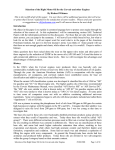
W A Technology
Changing My Own Oil:
Including; Checking Magnetic Drain Plugs and “Catch Can”
What Oil to Use?
In addition to Chevy recommending
Mobil 1 for use in, at least, the dry
sump C7, I was an early adopter of
the product.
My new Datsun 260Z was a great
car; however it was the 1st year of
new federally mandated pollution
controls that caused problems. The
“Z” had an exhaust air pump, hot
water channeled to the carburetors
etc. There was a problem when
accelerating rapidly and the Datsun
District Rep suggested using a
product Mobil made for the military
in Alaska, called Mobil 1. He said to
replace the oil in the two Hitachi SU
carburetor dash pots with Mobil 1. I recall it was hard to get and expensive. However it worked!
Reading about the product, I realized it might be good to put in my 1967 Corvair I had since new.
This air cooled engine often collected a creamy foam visible around the top of the oil inlet pipe.
The oil ran very hot, as evidenced by the oil temp gauge I added, even with my aluminum
aftermarket pan that had many conical cooling pins protruding into the crankcase. Sure enough,
Mobil 1 worked for the Corvair as well! Have used the product in my cars ever since. However, as
most if not all of todays “full synthetic” oils as they are called it has changed!
Mobil Loses Advertising Complaint:
Paraphrasing a 2000 Car and Driver article (I just recently found:) “Late in 1997, Castrol eliminated
the polyalphaolefins (PAO) synthetic base stock (constituting 70% of the product) and employed
specially refined Group III mineral based oil in their SynTec brand “Full Synthetic” offering. Mobil
brought a complaint to the National Advertising Division (NAD) of the Council of the Better
Business Bureau, asserting that this oil was not synthetic, but simply highly refined petroleum oil,
and therefore it was false advertising to call it synthetic. In 1999, the NAD with supporting
arguments from the SAE and API who had standards based on oil performance did not support
the Mobil complaint saying acceptable high performance oil could be made either way! It was
decided that the word "synthetic" was marketing term and referred to properties, not to
production methods or ingredients.” Good article still available on the Net:
“http://www.caranddriver.com/columns/pat-bedard-synthetic-motor-oil-gets-all-newsemantics-column”
Shortly after Mobil’s complaint was rejected, most oil companies started reformulating their
synthetic oils to use Group III mineral base stocks instead of truly synthetic stocks as their
primary component. Most of the "synthetic oil" you can buy today is made predominately of this
highly-distilled and purified mineral based oil called Group III. Group III base oils cost about half
as much as the true synthetics. By using a blend of mostly Group III oils and a smaller amount of
"true" synthetics, the oil companies can produce a product that has nearly the same properties as
the "true" synthetics, and nearly the same cost as the Group III oil. In fact, Mobil-1 is apparently
Copyright by WA Technology, LLC
www.NetWelding.com
Page 1
now primarily made from Group III unconventional base oils. In fact, I cannot find any motor oil
available in the US that says it is Group IV, which must be fully synthetic.
The old “synthetic motor oil” was made through chemical reactions unlike mineral oils that are
produced by refining of existing crude oil stock. Synthetic lubricants are recombined into
synthesized-hydrocarbon molecular chains with desirable characteristics and uniformity not
found in even the highest-quality traditional motor oils. Typically, the best synthetic oils use a
combination of synthetic base fluids--polyalphaolefins, synthetic esters, and alkylated aromatics.
These synthetic molecules are much more consistent in size and shape; they are better able to
withstand extreme engine temperatures. Since they are chemically produced, there are no
contaminants compared to conventional oils that contain small amounts of sulfur, wax, and
asphaltic material that can promote detonation as well as varnish and sludge buildup. Synthetics
flow at much lower temperatures than conventional oils.
However until it is clear from testing that there is an oil significantly better, I’ll stick with Mobil 1.
In 5 quart jugs (note not in quart containers) it’s about the same price as most other quality oils at
Walmart. In addition for this 2nd oil change a forum poster found a rebate offer and I was able to
purchase two 5 quart jugs for ~$3/quart after the rebate!
A Reason to Change My Own Oil
A forum poster made a comment that helped make my decision to change my own oil and not take
advantage of the GM 4 (now 5) free oil changes. He said, “do you think your dealer will have their
Corvette Certified Mechanic change your oil or a newbie?” It reminded me of an incident with my
1st new car! My 1967 Corvair was purchased with all the performance options available, quick
steering, HD suspension, and others. About that time, GM extended their warrantee but you had
to have the dealer change oil and filter. My uncle was the service manager at the large dealership
where I bought the car. (This was the same uncle who helped when I put the ’51 Olds engine,
bored an 1/8 inch to fit ’55 pistons, in my ’41 Ford Opera Coupe.) For the first oil change I brought
the car in for service. I had several Corvairs prior to the ’67 and was very concerned about folks
who did not understand that the aluminum heads and other parts could not be treated like cast
iron! I was watching the young mechanics helper who was working on my car as it was on the lift
and was obviously looking for something. I went over and inquired and he said, as I expected he
might, “looking for the oil filter!” In a Corvair the filter is in the engine compartment, not
accessible from under the car! I had to tell him where it was! I recall going into my uncle’s office
and saying I was going to do my own oil changes in the future and for sure change my own plugs
(a frequent requirement for a Corvair!) He said be sure to keep all receipts and that may help if
you have an engine warrantee issue. GM soon thereafter backed down on their requirement to
have a dealer do all maintenance, as long as you kept receipts!
There are a number of reported issues where C7’s with Dry Sumps had problems caused by a
dealers oil change. The system is sensitive to overfilling, which will cause oil to be expelled with
the “burped air” from the tank. To evacuate all the oil from the pan you need to pump a good deal
of air as well. That burped air from the Dry Sump Tank enters the air intake duct though a hose
exiting downstream of the air filter. If oil enters as well as air, it soaks the air filter and
contaminates the air intake duct!
It also takes time to change the oil. Will that newbie mechanic bring the oil up to temperature
before removing the old oil? Will they be sure to remove both drain plugs? Will they take the time
to allow all ~10 quarts to fully drain? Will they be careful not to overfill with their pump metered
filling nozzle (assuming they have Mobil 1 available as an option versus using whatever one of
over 100 brands that meet the GM dexos 1 they have in that 55 gallon drum?) Would they underfill
by a quart and check the level? That requires starting the car, having the oil reach temperature,
then when it is shut off, waiting 5 minutes (but not more than 10 per the manual) before checking
the level. If they wait too long some oil can drain back to the pan through the scavenge pump
resulting in a low oil level reading. Will they follow your request and leave the level ½ quart low to
help avoid oil “burping” into the air intake along with the air that is entrained with the oil as the
pan is pumped dry?
See pics of cleaning the “Clean Oil Separator” filter material that follows.
Copyright by WA Technology, LLC
www.NetWelding.com
Page 2
Photo How to Sequence
These are the tools I used. The 15 quart oil
drain pan has closures for all openings to
transport used oil to a recycling center.
Two Harbor Freight, low provide profile jacks
(~$60 each on sale.)
Four 2 inch high
Jacking Pucks since my car has side skirts.
Jack stands are also needed. Wheel chock
and ratchet wrench with extensions. Torque
wrench and metal pan are optional.
The wood stanchions are homemade, see
Appendix for details. Several forum posters
questioned their safety so I made Safety
Factor Calculations that are also included in
the Appendix!
This schematic shows the GM suggested
lifting points.
Note the preferred
locations are on the front and rear cradle.
These cradles are hollow castings so be
sure you’re not lifting in the center.
Details of how to build a Jack Cross
Brace are also in the Appendix. In this
case I used the “Optional Locations” on
the front cradle to place the Jack Stands.
With the two drain plugs, front and side of
the pan, having the car level provides the
best angle to get as much oil out as
possible. Therefore jacked up the rear
and put the wheels on the home built
Wooden Stanchions.
Jacked each side only 3 or 4 inches at a
time. Watch that the Jack moves in as
you lift.
The Jack should be
perpendicular to the car and the rear
casers turned to help it move. Especially
with a small jack that is necessary to
keep the jack saddle centered on the Jack
Puck! With my side skirts, 2 inch high
Jack Pucks are needed. These are from
Katech that also meet the GM requirement
of 2 ½ inches max diameter. They also
have 1 inch Jack Pucks.
Copyright by WA Technology, LLC
www.NetWelding.com
Page 3
This is a view of the two jacks lifting the front
on the 2 inch high Jack Pucks (red.) The
Jack Stands were placed on the “Optional
Locations” as noted on the GM chart. That
left room for the drain pan and access to the
front drain plug. The Jacks were left in place
and there was plenty of room to access the
side drain plug and oil filter. The stanchions
can be seen below the rear tires.
Note the flat metal pan is partially inserted
under the car. These are available at Auto
Parts stores for changing oil and also
stopping drips in a garage if that is an issue
with an old car. As typical, when I use it
there are no drips! If not, the concrete gets a
few small spills!
Place the drain pan under the oil drain plugs.
I did the side first. While the pan is draining
unscrewed the filter. Note, unscrew slowly
to allow oil to drain. A glove helps since it is
warm! There is a place in the drain pan to
place the filter upside down so it fully drains.
When finished draining installed the cleaned
drain plug and oil filter. Instead of the
Owner’s Manual that says to use 22 ft-lbs to
tighten the filter, which I found on the 1st oil
change was excessive and would have
distorted the gasket, I used what I always
have in the past and what the Service Manual
references. After putting oil in the new filter
run your clean finger over the gasket with
some new oil. Then tighten by hand until it
just seats than use ¾ to one full turn more.
Moved the drain pan under the front drain
plug.
Removed it with a long socket
extension and a 13 mm socket. That is the
size of the magnetic drain plug I used to
replace the OEM drain plugs on the 1st oil
change. The OEM drain plugs have a 15 mm
nut.
Copyright by WA Technology, LLC
www.NetWelding.com
Page 4
Purchased magnetic drain plugs from:
http://www.powerslutracing.com/oil-drainplugs.html with very powerful magnets.
Good info on their website about why they
should be used and magnet quality.
A forum poster, sahlbom, recently measured
the pulling force on these plugs at 36 oz,
which was 2.25 times that of one bought at
an auto parts store. He also found the
magnet had a far stronger attachment. Good
analytical information.
`This is the drain plug removed from the
front of the pan, the one that drains the
dry sump.
Very few and very fine
particles, cleaned with a paper towel. The
longer magnet side plug was the same.
Note the new gasket on the left.
If
purchased in quantity they are $0.95
each.
Well worth using a new one.
Interesting pricing, one cost $2.99, and 15
was less expensive that 14! No shipping
cost if allow them to US Mail.
This is a picture of the oil draining from the
front drain plug. Even though this drain pan/
transporting container is large, it is easier to
position it under each plug separately to
avoid the draining stream missing the pan!
Note I installed the drain plug and lowered
the car. You could try to fill the car with oil
and check for leaks at this point with it still
jacked up. However having done this many
times over the years and never having a
problem with plugs or filter leaking, I check
for leaks after filling (which is easier to do
with the car on the ground.) If there were a
problem would have to jack up the front but
the probability of that happening is very
remote!
Copyright by WA Technology, LLC
www.NetWelding.com
Page 5
Time to check the “catch can” to see
what was collected. Only checked it once
since the last oil change 3000 miles ago.
It had about 1 ounce about 1500 miles
ago. Note, I used a stud to replace the
bolt in the mounting location Elite
suggested.
That spot had a ground
connection so move it to the ground
connection a few inches forward. Used a
Nylon lock nut on the stud.
Once removed from the stud it is easy to
unscrew the bottom of the can by hand. No
need to remove the hoses unless cleaning
the oil vapor condensing ribbon material in
the top section. This time there was no need
to clean the stainless ribbon material, it
looked very clean.
The “O” ring seal
between top and bottom was fine. Put the
collected oil, ~1 ounce, in the jar on the right.
Not much, but better in the can than in the
intake or possibly “coking” around the intake
valve!
Just screwed it back on the can top and
bolted it back in place.
Now to remove the “Clean-Air Oil
Separator” to gain access to the fill
location. Originally, since it was shipped
as one piece, I was rotating it like a cap.
This meant removing the hose and lifting
the trim behind it to clear the hose barb!
A forum poster recently asked about just
separating the two parts! Did not know
they came apart! In fact I had to hold the
base in a vice and apply a lot of force to
get the two pieces apart! Once I took the
two pieces apart a few months ago, I oiled
the “O” ring and it was very easy to do for
this oil fill!
Copyright by WA Technology, LLC
www.NetWelding.com
Page 6
This is a view of the top half of the Clean-Air
Oil Separator removed and turned upside
down. Note the hose that “burps” air from
the tank into the air intake is left in place.
This is the bottom half of the “Clean-Air
Oil Separator” that remains in place. It is
fully turned clockwise to the stop, just
like the OEM cap. To remove the top
section, rotate the it slightly further
clockwise and it will rotate and the “O”
ring will loosen. It will then lift out easily.
Filled with ~8 ½ quarts, (note the Owner’s
manual says 9.8 quarts capacity) and ran
the engine to get the oil hot.
Then
checked the level.
Note while the car was running looked for
any leaks. None were visible.
Just as planned, when checking the level
after waiting 5 minutes (but less than 10
minutes) it was at the bottom of the
hatched area, about 1 quart low. Filled it
with ~ ½ quart more and checked. It was
right where it was before I started and
when I filled it the last time, half way in
the hatched are, ½ quart low. It did not
burn any significant amount of oil in the
3000 miles from last refill!
Keeping the level ½ quart low in
combination with the ”Clean-Air Oil
Separator” should avoid oil burping out
of the dry sump tank along with the air as
the air/oil is savaged from the pan.
I’ll check the level after I return from a
long ride where the oil gets to its typical
max temperature.
Copyright by WA Technology, LLC
www.NetWelding.com
Page 7
APPENDIX: Jacking Up A C7 Corvette
This section IS NOT for those happy with their present method of lifting
their C7, so skip it! . It is for those who aren’t either happy with their
current method or want to try the method shown here for this oil change.
Background: Worked on many cars with my Dad years ago. After we
jacked up a car we would use cement block(s) under the frame (our jack
stands!) Even with that, would have to hit the car with my shoulder to be
sure it was stable and could not fall! Dad had a friend crushed and killed
when working under a car that fell; he was justifiably very careful!
To have the C7 level, assuring all old oil is
drained, wood “stanchions” were fabricated.
I was somewhat surprised when a few forum
posters said they would not trust these to get
under a car! I commented that I could calculate
the loads they could hold but just stated they
were no doubt stronger than the commercial
ones you could buy for >$100 each or some
ramps I have seen!
For fun, decided to perform those calculations
and they are presented at the end of the
Appendix! You’ll see they have a conservative
Safety Factor of >~15!
Can’t 4 Jack Stands be Used?
No- Not Safely. Using 4 jack stands
does not provide a very stable support,
IMO. Would be concerned to try my
Dad’s required shoulder test!
Note the warning on this pair of jack
stands that I use, very good and rugged
ones. It states
“USE ONLY TO SUPPORT ONE END OF
A VEHICLE AT A TIME.”
If getting under the
especially important.
car
Copyright by WA Technology, LLC
this
is
www.NetWelding.com
Page 8
Building the Stanchions
First, I cut a twelve foot long 2x6 into 4
pieces 21 inches long and 4 pieces 9½
inch long. This makes two stanchions
12½ inches wide, sufficient to fit the
rear tires. With the ¾ inch plywood top
it makes a 6 ¼ inch high “stand.” Not
bad for an $8 investment (had some left
over plywood!) Be sure to make the
cuts square.
Assemble the cut pieces as shown in
this picture. Note the corner clamp
which makes it easy to assure a 90
degree fit when drilling for the first
screw but it’s not essential.
Don’t
follow
these
suggestions unless you have
the skills required to properly
cut and screw the pieces
together
Suggest using four 3 inch #8 screws to
join each corner joint. That provides 1
½ inches of gripping length. Pic shows
the 4 screws on one joint.
It can be seen in the calculations of
Safety Factor, that each screw in pine
will have a “Pull Out” force of 790 lbs.
Use a pilot drill somewhat
smaller than the root or minor
screw
diameter
before
inserting and screwing the
parts together.
Copyright by WA Technology, LLC
www.NetWelding.com
Page 9
The top was made with ¾ inch plywood. It not
only is supporting the tires it has a major
function of keeping what we’ll call the 2X6
“columns” from tilting. Considering the tensile
strength of plywood and the loading, it has a
Safety Factor of 35 based on its strength!
However their role in keeping the side 2X6
“columns” from tilting is more important as
we’ll see in the next item.
Straight compression of the column members
provides a Safety Factor of several hundred!
That is not a plausible failure mode. The
largest risk occurs if the “columns” are
subjected to a side load and the screws
holding the sides together and those securing
the plywood top to the side columns cannot
support the side load.
I was reminded of another possible approach
employed by Brunelleschi in the 1400’rds when
building a huge dome for cathedral in Florence
Italy. If interested, google or get an old best
seller “Brunelleschi’s Dome” by Ross King.
And he did it without the Internet that was a big
help (in addition to an old Strength of Materials
text book) in assisting with my Safety Factor
calculations!
How does the tire load cause a side load on the
2X6 “columns?”
If the deflection of the
plywood is sufficient then there will be a load
pushing the 2X6 columns outward. Calculating
that deflection, “X”, for a 1000 lb load
concentrated in the center would cause a
deflection of only, 0.02 inches. That creates a
side force of only 4 pounds! Even if 10,000 lbs
was centered on the top the deflection “X”
would only be 0.2 inches.
Calculated with a side load of 200 lbs (which
would need very poor construction or some
other defect.) As noted in the attached, the
Safety Factor would still be 15!
Check Out the Safety Factor
Assumptions and Calculations at the
End of this Appendix.
Copyright by WA Technology, LLC
www.NetWelding.com
Page 10
Jack Cross Brace
There are times when it is necessary to
lift the car using the jacking points on
the front and rear cradle. These are
shown on the picture directly below.
The picture right is a Cross Brace that
fits in place of the normal jack saddle.
Details of the one we made are
provided below.
Note the distance
between preferred and optional cradle
lifting locations.
This is particularly important on the C7
as parts of these members are hollow
and the car should not be lifted in the
center.
This Cross Brace was made from a 2x6. The
center pin that fits into the jack with the saddle
removed is made from a short section of steel
pipe (red circle) on the proper diameter. To
secure the pipe section a short heavy lag bolt
was screwed into the center of the 2X6. The
pipe section was then slipped over the lag
screw and the cavity filled with Epoxy.
Depending on the fit, may want to put some
clay or plumbers putty around the base of the
pipe to stop any leaks until the Epoxy sets.
Copyright by WA Technology, LLC
www.NetWelding.com
Page 11
This is a picture of the Cross Brace made for
my C6 and modified for the C7 by installing
sections of a 2X4 as pads that touch the
preferred jacking points. These are held in
place with two bolts that are set in a recessed
hole and protrude ¾ inches from the bottom.
These are placed in holes in the Cross Brace
that are slightly larger than the bolts.
This Cross Brace was cut in width for the C7 as
noted in the first photo above.
Why Not Use Ramps?
Many folks do and are pleased with that
approach; I tried and was not happy!
A friend used ramps to change oil on
his C6.
When I asked if he had
difficulty with the ramps slipping, he
said at times! When the C6 was new,
built the cross brace for my large
hydraulic jack but still needed to lift up
the front and back to make room for the
jack and cross brace. Decided to make
my own low profile ramps! As noted,
made four.
Used a 3 support rib design with ½ inch
particle board on top and bottom. They
were sufficiently strong, even used on
the wife’s CTS she had at the time. In
fact with her automatic trans they
seemed easier to use.
However one or both ramps would still
slip when driving the Vette up on them.
Note the “rubber runner starting” tabs
placed on the front of these finished
home fabricated ramps. Thought that
would help avoid them sliding forward.
Unfortunately they were no help!
Copyright by WA Technology, LLC
www.NetWelding.com
Page 12
Having gone through the effort of building the
ramps thought of a possible way to improve
them. Perhaps a higher friction material placed
on the bottom might help eliminate the ramps
moving when I tried to get the Vette up onto
them. In fact one would move and not the
other so I had to back off and start all over!
This was particularly an issue when on my
garage tiled floor but even occurred when on
my concrete driveway.
A fish scale and some weights provided
repeatable data for static and sliding friction
measurements! The result of these tests?
None of the materials tried, including rubber
runner material was much different than the
rough wood the ramps were made from!
Fun to do even though the results were not as
hoped!
Final Outcome:
Since I like to work on my own and not ask my wife to see if was up properly on the
ramps, or if one was moving, I gave them away! I wanted something I could safely and
quickly do on my own, ramps did not appear to be what would work for me! I gave them
away! A person who needs to raise their vehicle on grass, something I would not do and
can’t do with jacks, was very pleased to get the ramps! They worked fine for them!
Decided to use jacking pucks and a three jack approach. Two small jacks for the sides
on the Jacking Pucks and a large hydraulic jack on which the fabricated Cross Brace was
employed to contact the preferred jacking points. Finally replaced my old scissor jack
and cheap hydraulic jack with two low profile hydraulic jacks from Harbor Freight. As
noted in the C7 oil change report the two jacks work great with the 2 inch high Jacking
Pucks that are needed to provide the clearance for my side skirts. Safe, predictable and
reasonably fast.
There are many ways to jack-up a car. If you’re using one and are pleased-fine. However
if you are looking for a way to do it for a reasonable cost, I hope this information was
helpful in making your decision.
The next few pages show the calculations made to assure the home made “Wood
Stanchions” were safe. I don’t blame those who questioned their use, engineers can be
wrong! They said the Titanic Couldn’t Sink! However they are light compared to what
one forum poster who questioned their safety said he was going to do. He planned to
stack five 2X12’s to make “stanchions!” That would work but would weight about 50 lbs
each versus the 12 lbs for these fabricated wood “stanchions”!
Copyright by WA Technology, LLC
www.NetWelding.com
Page 13
W A Technology
Other Stingray PDF’s Available:
Some 37 items discuss improvements or information about the Stingray
function and/or esthetics. Some are minor and others, like the genuine carbon
fiber side skirts, include detailed install information.
Below are the PDF’s available. Click on picture (may need Ctrl pressed.) Or
just copy and paste the PDF info (Blue type) into your browser. Or email me at
[email protected] and state the title desired, shown in Yellow:
Rusty C7 Muffler
Why the C7 muffler is rusted and a simply way to
make rust turn matte black.
Bottom pic rusted, top pic treated
http://netwelding.com/Muffler_Rust.pdf
Change C7 Oil
WHY change your own oil and HOW to do it
Revised, includes C7 Lifting Methods
http://netwelding.com/Changing_Oil.pdf
Latch Hatch
Window Valet Helps 2014/2015 Latch
Includes M7 Crazy Seat Memory Recall
http://netwelding.com/Hatch_Latch.pdf
Copyright by WA Technology, LLC
[email protected]
C7 Carbon Fiber Side Skirts
How to install side skirts with jacking information for
DIY's without lifts
http://netwelding.com/Side_Skirts.pdf
Carbon Fiber Splitter w/End Plates
How to install Splitter & Nylon bra fit
http://netwelding.com/CF_Splitter.pdf
Removing GM Plastic Film
How To Remove The Rocker Panel Film
http://netwelding.com/Rocker_Panel_Film.pdf
C7 Mirrors 2 3/8" Wider Than C6
Device assists with 8 foot garage door
http://netwelding.com/Narrow_Garage_Device.pdf
Mirror Proximity Alarm
Limit switch alarm warns when passenger mirror is
too close to door frame
http://netwelding.com/Mirror_Proximity_Alarm.pdf
Making Jacking Pads for C7
Jacking Pads must 2 1/2 inch max OD. Made four.
Also Hockey Puck pad and 2 1/2 inch OD x 2 inch
high pads bought after installing side skirts.
http://netwelding.com/Jacking_pads.pdf
C7 Radar Power
The C7 cannot tap the mirror or sun visor for power !
http://netwelding.com/Radar_Detector_Power.pdf
C7 Belt Rattle
Passenger seat belt rattles against the seat back. The
solution, add a shoulder belt pad.
http://netwelding.com/Eliminate_Rattle.pdf
Aluminum C7 Chassis and Weld Repair
The C7 has an all aluminum chassis, made from 117
welded pieces
http://netwelding.com/Aluminum_Chassis.pdf
Carbotech Ceramic Brake Pads
The Z51 has very dusty brakes. These pads help!
http://netwelding.com/Ceramic_Pads.pdf
Copyright by WA Technology, LLC
[email protected]
C7 License Plate Frame;
Must Meet South Carolina Law
http://netwelding.com/License_Plate_Frame.pdf
Manage C7 Spilled Gas
Protect the side of the C7 when filling up with gas
http://netwelding.com/Manage_Spilled_Gas.pdf
C7 License Plate & Cargo Lights
LED license plate light & cargo area bulbs are
brighter and whiter
http://netwelding.com/License_Plate_Light.pdf
C7 Rear Cargo Area
Rear cargo area needs storage device and rear
protector
http://netwelding.com/Rear_Cargo_Area.pdf
C7 Door Panel Protector
protector plate added to prevent scuffing of door
when exiting
http://netwelding.com/Door_Panel_Protector.pdf
C7 Improved Cup Holder
A solution to the cup holder spilling under hard
braking or shape turns.
http://netwelding.com/Improved_cup_Holder.pdf
C7 Wheel Chatter/Hop
Why sharp, low speed turns with cold tires causes
the front tires to chatter/hop.
http://netwelding.com/Wheel_Chatter.pdf
Carbon Fiber Grille Bar
Install genuine carbon fiber grille bar overlay
http://netwelding.com/CF_Grille_Bar.pdf
Jacking a C7 Vette
Safely jacking either front only or back and front
http://netwelding.com/Jacking_A_C7.pdf
Copyright by WA Technology, LLC
[email protected]
Deer Whistle Installed on C7
Do they work? Plus Install Info
http://netwelding.com/Deer_Whistle.pdf
C7 Battery Issues
Even after using a GM type charger and showing fully
charged, voltages were still low!
http://netwelding.com/Battery_Issues.pdf
C7 Splash Guards
GM offers splash guards for the C7 Corvette. An easy
DIY installation.
http://netwelding.com/Splash_Guard.pdf
C7 Blind Spot Mirror
Smaller rear and side windows cause C7 blind spots.
Small "blind spot mirrors" help
http://netwelding.com/Blind_Spot.pdf
C7 Skid Pad Protector
After the air dam, the aluminum "skid pad" hits
driveway ramps etc. Plastic protector helps.
http://netwelding.com/Skid_Pad_Protector.pdf
C7 Wheel Locks
Wheel locks, torqued to required 100 ft-lbs, help
protect your expensive wheels from theft.
http://netwelding.com/Wheel_Locks.pdf
C7 OnStar Lights
The OnStar LED's in the rear view mirror, at a quick
glance, look like a police car flashing light! This is a
fix.
http://netwelding.com/OnStar_Lights.pdf
C7 Skip Shift Eliminator
Skip Shift Eliminator install with suggestions on
jacking a C7.
http://netwelding.com/Skip_shift_Eliminator.pdf
Copyright by WA Technology, LLC
[email protected]
C7 Catch Can & Clean Oil Separator
Direct inject engines like the LT1, are particularly
subject to “coking.” What is Coking and how to
reduce the potential?
http://netwelding.com/Catch_Can.pdf
C7 Round Shift Knob
A round shift knob shortens throw.
http://netwelding.com/Shift_Knob.pdf
C7 Stingray Sill Plate
Stingray sill plate replaces original.
http://netwelding.com/Sill_Plate.pdf
C7 Nylon Bra
Nylon Bra Stops Bugs on Front and Grill.
http://netwelding.com/Nylon_Bra.pdf
C7 Clutch Fluid Change
Clutch fluid after 3000 miles gets dirty
http://netwelding.com/Clutch_Fluid.pdf
Carbon Fiber Hood Vent
Replaces Plastic Hood Vent
http://netwelding.com/Hood_Vent.pdf
Cold Air Intake
Low Restriction Air Filter & Duct
http://netwelding.com/Cold_Air_Intake.pdf
May Be Of Interest:
Engineering a ProStreet Rod
How Our ’34 ProStreet Rod Was Designed and Built
8.2 Liter Engine, 4 Wheel Disk Brakes & Coilover
http://netwelding.com/Engineering%20Street%20R
od%203-08.pdf
Copyright by WA Technology, LLC
[email protected]