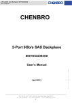
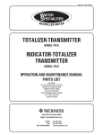
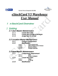
1
IMAGE-VET 70 PLUS
Troubleshooting Reference
Trained Service Personal ONLY
Observe ALL safety Procedures in the service manual
Reference: Installation, Operation, Service & parts Manual (P/N: 897-000002)
Table of Contents
1) Wiring Connections_______________________________________1
2) No X-Ray or Light X-Ray__________________________________1
3) Error Codes____________________________________________2-3
4) Miscellaneous____________________________________________4
Key
> Greater Than
< Lower Than
= Equal To
≈ About the Same
1) I.
Wiring Connections
Three wiring are coming out of the x-ray tube and are connected as follows:
a) The black wire (L) is connected to number 10 on the bar closest to the switch.
b) The white wire (N) is connected to number 16 on the bar closest to the switch.
c) Green-yellow is connected to ground (metal screw second on the left from the power switch).
d) Place a jumper between 8 & 9 on the bar located further away from the switch (on the other side of the board).
e) For Hand-Held usage make sure the jumper J1 (next to the above bar) is covering middle and right pins.
f) For Remote Expose Switch make sure the jumper J1 (next to the above bar) is covering middle and left pins.
Switch Connections
II.
Position the control box so you can read the label next to the power switch.
a) The upper left and upper right metal stripes of the power switch are connected to number 5 & 6 on the bar
closest to the switch, respectively.
b) The lower left and lower right metal stripes of the power switch are connected to number 4 & 7 on the bar
closest to the switch, respectively.
2) No X-Ray or Light X-Ray.
No X-Ray
Make sure that the wire connections above are
accurate and that you have power from the wall.
Connections are accurate
Connections are not accurate
Check Fuse F1 on the PC Board
(Located in a black cylinder that
has to be rotated to be opened)
Fuse is Good
Fix wire connections.
Fuse is Bad
Check the voltage between 10 & 16 on the
bar closest to the Power Switch during an
exposure (should be line voltage).
Voltage
Replace Fuse F1
P/N: 897-FU0001007 (Vet).
No Voltage
Turn down the machine and check
the resistance between 10 & 16 on
the bar closest to the Power Switch
(should be between 1.2-1.6 Ω)
Resistance Good
Machine should work.
Replace Board
P/N: 897-ZZ1145021 (115V).
P/N: 897-ZZ1145051 (230V)
Resistance Bad
∞
Check the resistance of the tube head.
(should be between 1.2-1.6 Ω).
Resistance Good
Replace the Arm.
P/N: 9992700105 (Folding Arm).
P/N: 9992700108 (Extension Arm).
1
Resistance Bad
Replace the Tube Head.
P/N: 9992700130 (115V)
P/N: 9992700330 (230V)
3) Error Codes
a) E001: x-ray exposure button was released too fast.
b) E002:
E002
Frequency is incorrect
Turn the machine off and remove J3 from the PC board (it is located on the left edge when facing the
power switch on the control box) make sure it is clean and put it back in place (covers both pins).
Turn the machine on
Problem Solved
Machine is good
Problem wasn’t solved
Try to use another jumper and if it doesn’t work, call
electrician. The frequency problem is coming from the wall.
If the frequency coming out from the wall is good, replace the
board. P/N: 897ZZ1145021 (115V) / 897-ZZ1145051 (230V)
c) E003-Turn the machine off and then on. If the problem persists, replace the PC Board.
d) E004 / E005:
The operational voltage range is 108 < V < 126. If the error message is E004 / E005 than the voltage supply is
above or below this range, respectively. Call an electrician to fix the problem.
e) E006: -Two or more X-ray tubes may have been pulled out- Make sure that all tube heads besides one are in
Position.
-Equipment selector switch may be faulty.
-Check wiring.
f) E009:
Check Fuse, F1,
Replace fuse F1:
located in a black
P/N: 897FU0001013
Fuse Bad
tube on the PC
Board.
Fuse Good
Voltage & Resistance Good
Machine
should work
-Turn Off the machine and then turn it On. That will enable you to
take one additional exposure. Check that the voltage between 10 &
16 on the bar closest to the Power switch during an exposure is about
line voltage (≈115V).
-Check the resistance between 10 & 16 on the bar closest to the
Power switch when the machine is shut down (≈1.2Ω-1.6Ω)
Voltage Good-Resistance Bad
No Voltage
Check the resistance of the tube head
(Should be between 1.2Ω-1.6Ω)
Resistance Good
Replace the Arm
P/N: 9992700105 (Folding Arm)
P/N: 9992700108 (Standard Extension Arm (35.4”))
Replace PC Board
P/N: 897-ZZ1145021 (115V).
P/N: 897-ZZ1145051 (230V)
Resistance Bad
2
Replace the Tube
P/N: 9992700130 (115V)
P/N: 9992700330 (230V)
g) E010:
Check if wiring
is accurate
Wiring Good
Wiring Bed
Make sure the J6 on the control
box is open, i.e.: it doesn’t cover
both pins (cover only the left
one). J6 is located on the left
edge of the PC Board when
facing the Power switch.
J6 Covers One Pin
J6 Covers both Pins
Check that the voltage between 10 &
16 on the bar closest to the Power
switch is 115V during an exposure and
that the resistance is between 1.2-1.6Ω
(Shut down the machine before
checking the resistance)
Voltage & Resistance Good
Machine
should work
Fix connection according
to the instruction.
Remove it and place it so
it covers only the left pin.
Voltage Good-Resistance Bad
Check the resistance of the tube head
(Should be between 1.2-1.6Ω
Resistance Good
Resistance Bad
Replace the Arm
P/N: 9992700105 (Folding Arm)
P/N: 9992700108 (Standard Extension Arm (35.4”))
No Voltage
Replace PC Board
P/N: 897-ZZ1145021 (115V).
P/N: 897-ZZ1145051 (230V)
Replace the Tube
P/N: 9992700130 (115V)
P/N: 9992700330 (230V)
3
4) Miscellaneous
a) No Ready Light: Make sure that the jumper between 8 & 9, on the bar furthest from the Power Switch, is in
place.
b) Machine Doesn’t Work but Everything Else is Fine: Check that J1 is to the right and covers pins 1 & 2. J1
location determines whether the Hand-Held device is used or whether an external device is used (J1 is located
on the opposite side to the Power Switch).
c) Setting the System in Remote Control Mode: Move J1 to the right so it covers the left and middle pins (orient
the control box so you would be able to read the label next to the Power Switch.
d) Machine Just Clicks but doesn’t operate: Check that K2 on the PC board is in place (located on the upper-right
corner when you orient the control box so you are able to read the label next to the Power Switch). Check that
the connections on the hand-held control are in place as well.
e) For duel tube head operations place a jumper between 14 & 17 on bar M2.1 (The one closest to the Power
Switch). In addition, connect:
Number 13 on bar M2.1 to tube head B and to wall mount.
Number 11 on bar M2.1 to tube head B and to wall mount.
Number 10 on bar M2.1 to tube head A and to wall mount.
The micro-switches provided are to be connected as follows:
-Tube A is connected between terminals 8 & 9 on the M1 bar in the control box and the lower terminal 8 & 9 on
the steel mounting plate.
-Tube B is connected between terminals 8 & 10 on the M1 bar in the control box and the lower terminal 8 & 9
on the steel mounting plate.
4