1
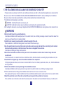
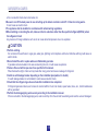
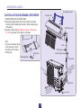
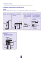
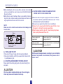
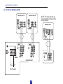
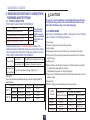
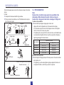
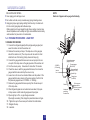
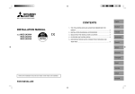
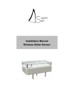
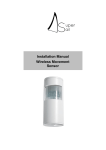
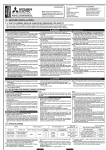
Thank you very much for purchasing this Air Conditioner. Please
read this use and installation instructions carefully before installing
and using this appliance and keep this manual for future reference.
INSTALLATION MANUAL
Outdoor Unit:
AMW2-20U4SNC1
AMW2-16U4SGC1
AMW2-20U4SZD1
AMW2-16U4SGD1
The following should always be observed for safety..............01
Installation diagram&accessories...........................................03
Selecting the installation location............................................04
Outdoor unit installation.........................................................04
Indoor/outdoor units connection finishing and test run...........09
Refrigerant flow diagram........................................................12
INSTALLATION MANUAL
1.THE FOLLOWING SHOULD ALWAYS BE OBSERVED FOR SAFETY
·Please provide an exclusive circuit for the air conditioner and make sure that no other electrical appliances are connected to it.
·Be sure to read <THE FOLLOWING SHOULD ALWAYS BE OBSERVED FOR SAFETY> before installing the air conditioner.
·Be sure to observe the caution specified here as they include important items related with safety.
·The indications and meanings are as follows.
WARNING: Could lead to death, serious injury, etc.
CAUTION: Could lead to serious injury in particular environments when operated incorrectly.
·After reading this manual, be sure to keep it together with the INSTRUCTION MANUAL in a handy place on the customer's site.
WARNING
·Dot not install the unit by yourself(customer).
Incomplete installation could cause injury due to fire, electric shock, the unit falling or leakage of water. Consult the dealer from
whom you purchased the unit or special installer.
·Install the unit securely in a place which can bear the weight of the unit.
When installed in an insufficient strong place, the unit could fall and cause injury.
·Use the specified wires to connect the indoor and outdoor units securely and attach the wires firmly to the terminal
block connecting sections so that the stress of the wires is not applied to the sections.
Incomplete connecting and fixing could cause fire.
·Do not use intermediate connection of the power cord or the extension cord and do not connect many devices to
one AC outlet.
It could cause a fire or an electric shock due to defective contact, defective insulation ,exceeding the permissible current, etc.
·Check that the refrigerant gas does not leak after installation has completed.
If refrigerant gas leaks indoors, and comes into contact with the fire of a fan heater, space heater, stove, etc., harmful substances
will be generated.
·Perform the installation securely referring to the installation manual.
Incomplete installation could cause a personal injury due to fire, electric shock, the unit falling or leakage of water.
·Perform electrical work according to the installation manual and be sure to use an exclusive circuit.
If the capacity of the power circuit is insufficient or there is insufficient electrical work ,it could result in a fire or an electric shock
·Attach the electrical cover to the indoor unit and the service panel to the outdoor unit securely.
If the electrical cover in the indoor unit and/or the service panel in the outdoor unit are not attached securely, it could result in
01
INSTALLATION MANUAL
a fire or an electric shock due to dust water, etc.
·Be sure to cut off the main power in case of setting up the indoor electronic control P. C. Board or wiring works.
It could cause an electric shock.
·The appliance shall be installed in accordance with national wiring regulations.
·When installing or relocating the unit, make sure that no substance other than the specified refrigerant(R410A) enters
the refrigerant circuit.
Any presence of foreign substance such as air can cause abnormal pressure rise or an explosion.
CAUTION
·Perform earthing.
Do not connect the earth wire to a gas pipe, water pipe, lightning rod or telephone earth wire. Defective earthing could cause an
electric shock.
·Do not install the unit in a place where an inflammable gas leaks.
If gas leaks and accumulates in the area surrounding the unit, it could cause an explosion.
·Fasten a flare nut with torque wrench as specified in this manual.
When fastened too tight, a flare nut may break after a long period and cause a leakage of refrigerant.
·Install an earth leakage breaker depending on the installation place(where it is humid).
If a earth leakage breaker is not installed, it could cause an electric shock.
·Check that the refrigerant gas does not leak after installation has completed.
If refrigerant gas leaks indoors, and comes into contact with the fire of a fan heater, space heater, stove, etc., harmful substances
will be generated.
·Perform the drainage/piping work securely according to the installation manual.
If there is a defect in the drainage/piping work, water could drop from the unit and household goods could be wet and damaged..
02
INSTALLATION MANUAL
A:Installation plate
2.INSTALLATION DIAGRAM&ACCESSORIES
B:Indoor unit
DRAIN PIPING FOR OUTDOOR UNIT
·Provide drain piping before indoor and outdoor connection.
(It will be hard to install drain socket ,if indoor unit becomes
immovable.)
·Connect the drain hose(obtainable at a store ,inside diameter:15mm) as shown in the figure for drainage.
C:Wall hole cover
Putty
Note:
Do not use the drain elbow
in the cold region. Drain
may freeze and it makes
the fan stop.
Pipe
Piping tape
Drain hose
Pipe fixing band
Drainage elbow
Fixing screw
Mo
re t
han
100
mm
mm f
100 m i o
han 200mcles t
t
e
n
r
a
Mo re tha obst
Mo re are s.
the h side
bot
Drain hose
le
as a ru
m if
More an 500m es
th
id
More ck ,both s
n
a
the b p are ope
and to
03
More than 350mm
INSTALLATION MANUAL
3.SELECTING THE INSTALLATION LOCATION
OUTDOOR UNIT
·Where it is not exposed to strong wind.
·Where airflow is good and dustless.
·Where it is not exposed to rain and direct sunshine.
·Where neighbours are not annoyed by operation sound or hot air.
·Where rigid wall or support is available to prevent the increase of operation sound or vibration.
·Where there is no risk of combustible gas leakage.
·Where it is at least 3m away from the antenna of TV set or radio. An amplifier may be required for the affected device.
·Install the unit horizontally.
·Please install it in an area not affected by snowfall or blowing snow. In areas with heavy snow, please install a canopy, a pedestal
and/or some baffle boards.
4.OUTDOOR UNIT INSTALLATION
CAUTION
Avoid the following places for installation where air conditioner trouble is liable to occur.
·Where there is much machine oil.
·Salty places such as seaside.
·Where sulfide gas is generated such as a hot spring.
·Where there is high-frequency or wireless equipment.
Note:
When operating the air conditioner in low outside temperature, be sure to follow the instruction describe below.
·Never install the outdoor unit in a place where its air inlet/outlet side may be exposed directly to wind.
·To prevent exposure to wind, install the outdoor unit with its air inlet side facing the wall.
·To prevent exposure to wind, it is recommended to install a baffle board on the air outlet side of the outdoor unit.
04
INSTALLATION MANUAL
4-1 FREE SPACE REQUIRED AROUND OUTDOOR UNIT(Unit:mm)
Obstacles
When there is an obstacle around the outdoor unit, it does not matter if the position of the obstacle as shown in the figures below.
(1).Obstacle over the top side.
(2).Obstacle in three direction(bu top
side is open) .
(3).Obstacle on front(blowing)
side only. In this case, the
rear, both side and top should be open.
100 or more
(4).Obstacle on front and rear side
only. The unit can be used by
attaching an optional outdoor
blowing guide(but both sides and
top are open).
200 or more
100 or more
500 or more
500 or more
100 or more
350 or more
(5).Service space
Keep the service space as shown
in the figure below for maintenance
Service space
100 or more
500 or more
100 or more
500 or more
350 or more
05
500 or more
Blowing guide
INSTALLATION MANUAL
·When installing the unit in an area that is enclosed on four sides
4-4 OUTDOOR WIRE CONNECTION AND OUTDOOR
such as a verandah, be sure to leave move than 200mm behind
POWER SUPPLY CORD CONNECTION
the unit as shown.
·When there is a lack of airflow or there is a possibility of becom·Be sure to lead in the power supply cord to the air conditioner
ing short cycle, install an outlet guide and make sure there is enin accordance with the specification tables below and ``Techniough space behind the rear side of the air inlet.
cal Standards for Electrical Installation``.
· Be sure to use special circuits for room air conditioner.
NOTE:
·Connect to the power switch which has a gap of 3mm or more
Make sure not to install several outdoor units sideways next
then open to interrupt the source power phase.
to each other.
·When the power switch is shut off, it must interrupt all phases.
Input capacity Main switch/Fuse:20A
Window
More than 100mm
More than
100mm
More than 100mm
More than
200mm
Power supply cord
specification
More than
350mm
Less than 1,200 mm of the
front surface side
4-2 INSTALLING THE UNIT
·Be sure to fix the unit`s legs with bolts when installing it.
·Be sure to install the unit firmly to ensure that it does not fall
by earthquake or gust.
Indoor and outdoor
connecting wire specification
Cable 3-core 2.5mm2, in conformity with
Design 245 IEC 57.
Cable 4-core 0.75mm2, in conformity with
Design 245 IEC 57.
CAUTION
Attach an earth leakage breaker according to your installation
location. If any breaker is not attached, it may cause a risk of
electric shock.
4-3 MOUNTING ARRANGEMENT OF DRAIN SOCKET
Please perform the drain piping work only when draining from
one place.
CAUTION
Do not use drain socket and drain cap in the cold region.
Drain may freeze and it makes the fan stop.
06
INSTALLATION MANUAL
4-5 ELECTRICAL WIRING DIAGRAM
INDOOR UNIT A
INDOOR UNIT B
NOTE: For multi split and one
for one common indoor unit the
wiring diagram.
INDOOR UNIT
0
0
1(L) 2(N) 3(
1(L) 2(N) 3(
)
)
OUTDOOR UNIT
To Power
07
MULTI SPLIT OUTDOOR UNIT
INSTALLATION MANUAL
WARNING
Be sure to comply with ``Technical Standards for Electrical Installation``, follow this manual and use special circuits for electrical work. If there is a lack of circuit capacity or some deficiency in installation, it may cause a risk of electric shock.
Overcurrent might be produced may include DC substances. Be careful to choose the correct type of overcurrent protection switch.
POWER TERMINAL
PANEL
1(L) 2(N) 3
1(L) 2(N)
WARNING
4(SI)1(L) 2(N)
Cable clamp
Power Cord
To indoor unit A
4(SI)
1.Remove the screw of
terminal cover.
2.Connect the wire and power
supply cable to the terminal
block.
3.Replace the terminal cover
securely.
To indoor unit B
-Be sure to attach the valve cover of the outdoor unit securely, otherwise it may result in a fire or an electric shock from dust
or water.
-Use the indoor/outdoor unit connecting wire that meets the Standards to connect the indoor and outdoor units and fix the
wire to the terminal block securely so that no external force is conveyed to the connecting section of the terminal block.
Incomplete connections or fixing of the wire could result in a fire.
-Be sure to attach the terminal block cover on both indoor and outdoor units. If the terminal block cover is incorrectly attached,
it may cause a risk of fire or electric shock due to dust or water penetration.
-Be sure to use the power cord which type is more than 20A, otherwise it may result in a fire.
08
INSTALLATION MANUAL
5. INDOOR/OUTDOOR UNITS CONNECTION
FINISHING AND TEST RUN
CAUTION
Be sure to use the insulation of specified thickness. Excessive thickness may cause incorrect installation of indoor unit
and lack of thickness may cause dew drippage.
5-1 FLARED CONNECTION
PIPE LENGTH AND HEIGHT DIFFERENCE
LIMITS
Pipe length per indoor unit
Total pipe length for multi-system
Height difference(I.D ~ O.D)
Height difference(I.D ~ I.D)
TYPE
20m*
40m
10m
7.5m
*Do your best to
reduce the pipe
length. Long pipe
may cause capacity
of the indoor unit
incline.
Refrigerant adjustment: If total pipe length exceeds 15m,
additional refrigerant (R410A) change is required.(The outdoor
unit is charged with refrigerant for total pipe length up to 15m. )
PIPE LENGTH AND HEIGHT DIFFERENCE
Pipe length
Up to 15m
No additional charge is required
Exceeding 15m Additional charge is required.
Refrigerant
15g/m × (refrigerant piping length(m)-15)
to be added
PIPE SIZE
If you use commercially available copper, use the following table for
specifications.
Valve size for outdoor unit
Liquid pipe φ6.35mm
UNIT A
Gas pipe
φ9.52mm
UNIT B
Liquid pipe
Gas pipe
φ6.35mm
φ9.52mm
Wall thickness Insulation thickness
0.8mm
8mm
0.8mm
8mm
8mm
0.8mm
8mm
0.8mm
5-2 FLARING WORK
Main cause of gas leakage is defect in flaring work. Perform flaring
work correctly in the following procedure.
1.Pipe cutting
·Cut the cooper pipe correctly with pipe cutter.
2.Burrs removal
·Completely remove all burrs from the cut cross section of the pipe.
·Put the end of the copper pipe downward to prevent burrs from dropping in the pipe.
3.Putting nut on
·Remove flare nuts attached to indoor and outdoor units, then put them
on pipe having completed burr removal.
(Not possible to put them on after flaring work).
·Flare nut for R410A pipe may differ from R22 pipe depending on the diameter of pipe.
4.Flaring work
·Perform flaring work using flaring tool as shown below.
Outsdie
diameter
φ6.35mm
φ9.52mm
φ12.7mm
φ15.88mm
09
Flare tool for
R410A clutch type
0 to 0.5
0 to 0.5
0 to 0.5
0 to 0.5
A(mm)
Conventional flare tool
Clutch type
Wing nut type
1.0 to 1.5
1.0 to 1.5
1.0 to 1.5
1.0 to 1.5
1.5 to 2.0
1.5 to 2.0
2.0 to 2.5
--
INSTALLATION MANUAL
Firmly hold copper pipe in a die in the dimension shown in the table
above.
5.Check
·Compare the flared work with the figure below.
·If flare is noted to be defective, cut off the flared section and perform flaring work again.
No good
Good
o
Tilted Uneven Burred
90
1.Indoor unit connection
·Connect both liquid pipe and gas pipe to indoor unit.
-Apply a thin coat of refrigeration oil to the seat surface of pipe.
-For connection, align the center of both pipe and union, then tighten
the first 3 to 4 turns in flare nut by hand.
-For tightening the union part of the indoor unit side, use the table below
as a standard and tighten the flare nut with two wrenched. Excessive
tightening damages the flared section.
Flare nut
Copper pipe
Burr
5-3. PIPE CONNECTION
Note:
Fasten a flare nut with a torque wrench as specified in the
table below. When fastened too tight, a flare nut may be
broken after a long period and cause a leakage of refrigerant.
Spare
reamer
Pipe cutter
Pipe diameter
Copper pipe
φ6.35mm
φ9.52mm
φ12.7mm
φ15.88mm
Flaring tool
Clutch type
Wing nut type
Inside is shining without any scratches
Smooth all around
Die
Flare nut
Tightening torque
Kgf·cm
13.7 to 17.7
34.3 to 41.2
49.0 to 56.4
73.5 to 78.4
140 to 180
350 to 420
500 to 575
750 to 800
2.Outdoor unit connection
·Connect pipe to the pipe joint part of the stop valve in the same method
as the indoor unit.
-For tightening, use the same tightening torque applied for indoor unit
and tighten the flare nut with torque wrench or spanner.
York
Die
Copper pipe
N·m
Copper pipe
10
INSTALLATION MANUAL
NOTE:
Each set of pipes must be purged individually.
INSULATION AND TAPING
·Cover piping joints with pipe cover.
·For outdoor unit side, surely insulate every piping including valves.
·Using piping tape, apply taping starting from the entry of outdoor unit.
-Fix the end of piping tape with adhesive tape.
-When piping has to be arranged through above ceiling, closet or area
where temperature and humidity are high, wind addtional commercially
sold insulation for prevention of condensation.
5-4. PURGING PROCEDURES·LEAK TEST
1.PURGING PROCEDURES
(1)Connect the refrigerant pipes(both liquid pipe and gas pipe) between the indoor unit and the outdoor unit.
(2)Remove the service port cap of the stop valve on the gas pipe
side of the outdoor unit. (The stop valve will not work in it initial
state fresh out of the factory [totally closed with cap on].)
(3)Connect the gauge manifold valve and vacuum pump to the service port of the stop valve on the gas pipe side of the outdoor unit
(4)Run the vacuum pump. Vacuumize for more than 15 minutes.
(5)Check the vacuum with the gauge manifold valve, then close the
gauge manifold valve and stop the vacuum cap.
(6)Leave it as is for one or two minutes. Make sure the pointer of the
gauge manifold valve remains in the same position. Confirm that
the pressure gauge shows -0.101MPa or -760mHg .
(7)Remove the gauge manifold valve quickly from the service port
of the stop valve.
(8)After refrigerant pipes are connected and evacuated, fully open
all stop valves on both sides of gas pipe and liquid pipe.
(9)Pipe length up to 15m, no gas charge is needed.
Pipe length exceeding 15m,charge the prescribed amount of gas.
(10)Tighten the cap to the service port to obtain the initial status.
(11)Retigten the cap.
(12)Leak test.
-0.101MPa
(-760 mmHg)
Handle
Low
Compound pressure
gauge(for R410A)
Pressure gauge
(for R410A)
Gauge manifould
Valve(for R410A)
Handle High
Charge hose
(for R410A)
Window
Adapter for
preventing
the back flow
11
(Or the vacuum
pump with the
function to prevent
the back flow)
INSTALLATION MANUAL
6. REFRIGERANT FLOW DIAGRAM
INDOOR UNIT
OUTDOOR UNIT
UNIT A
4-WAY VALVE
UNIT B
FILTER
UNIT A
Cooling cycle
Heating cycle
12
OUTDOOR HEAT EXCHANGER
COMPRESSOR
ACCUMULATOR
INDOOR HEAT EXCHANGER- B
INDOOR HEAT EXCHANGER- A
UNIT B
Outdoor unit
1
1
1
THE SYMBOL "*" STANDS FOR THE PART
TO BE PICKED AND MADE PURCHASE.
Correct Disposal of this product
This marking indicates that this product should not be disposed with
other household wastes throughout the EU. To prevent possible
harm to the environment or human health from uncontrolled
waste disposal, recycle it responsibly to promote the sustainable
reuse of material resources. To return your used device, please
use the return and collection systems or contact the retailer where
the product was purchased. They can take this product for
environmental safe recycling.
Version NO. 1350437,G