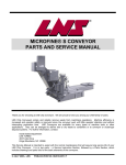
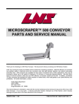
1
MICROFINE® CONVEYOR
PARTS AND SERVICE MANUAL
Thank you for choosing an LNS Chip Conveyor. We are proud to have you among our LNS family of users.
LNS Chip Conveyors simply and reliably remove waste from machining operations. Machine efficiency is
increased and operator safety is improved since chip conveyors work with little operator attention and without
interrupting production time. LNS conveyors are available for many types of machine tools or other applications.
They can be arranged to deliver wet or dry waste to containers or to conveyor or chute-type disposal systems.
For further information, contact:
Inside Sales Department
LNS TURBO
203 Turbo Drive
Kings Mountains, NC 28086
This Service Manual is intended to assist with the normal maintenance that will assure long service life of your
LNS Chip Conveyor. It is in two parts – a Service Instruction Section, followed by a Parts Section, which includes
drawings and parts lists for the basic elements of the conveyors.
©FEBRUARY. 2001 TURBO SYSTEMS INC...................................... PUBLICATION NO. 864510-0003 REV. 2
Page 1
TURBO MICROFINE® CONVEYOR PARTS AND SERVICE MANUAL
NOTICE
ALL INFORMATION CONTAINED IN THIS MANUAL IS INTENDED TO BE CORRECT; HOWEVER
INFORMATION AND DATA IN THIS MANUAL ARE SUBJECT TO CHANGE WITHOUT NOTICE. LNS
MAKES NO WARRANTY OF ANY KIND WITH REGARD TO THIS INFORMATION OR DATA. FURTHER,
LNS CONVEYOR IS NOT RESPONSIBLE FOR ANY OMISSIONS OR ERRORS OR CONSEQUENTIAL
DAMAGE CAUSED BY THE USER OF THE PRODUCT. LNS RESERVES THE RIGHT TO MAKE
MANUFACTURING CHANGES WHICH MAY NOT BE INCLUDED IN THIS MANUAL.
LNS supplies data necessary for the proper instruction, test, operation and maintenance of this product. LNS
retains all proprietary rights in and to the information so disclosed and such shall not be reproduced, copied, or
used in whole or in part for purposes other than those for which it is furnished.
CONTENTS
PAGE
GENERAL. . . . . . . . . . . . . . . . . . . . . . . . . . . . . . . . . . . . . . . . . 1
PART ORDERING AND WARRANTY . . . . . . . . . . . . . . . . . . . 2
START-UP INSTRUCTIONS. . . . . . . . . . . . . . . . . . . . . . . . . 3-5
PERIODIC INSPECTION. . . . . . . . . . . . . . . . . . . . . . . . . . . . 5-7
TROUBLE SHOOTING. . . . . . . . . . . . . . . . . . . . . . . . . . . . . . 8-9
REPAIR AND PARTS REPLACEMENT. . . . . . . . . . . . . . . . 9-14
BACKWASH PUMP . . . . . . . . . . . . . . . . . . . . . . . . . . . . . . . . 14
BELT REMOVAL AND INSTALLATION INSTRUCTIONS . 14-18
AIR HEADER INSTALLATION & OPERATION . . . . . . . . . . 18-19
MICROFINE® SERVICE PARTS . . . . . . . . . . . . . . . . . . . . 20-23
MICROFINE® FILTER DRUM SERVICE PARTS . . . . . . . . 24-25
MICROFINE® BACKWASH PUMP SERVICE PARTS . . . . 26-27
ELECTRICAL INFORMATION . . . . . . . . . . . . . . . . . . . . . . 28-31
INSTRUCTIONS FOR ORDERING PARTS
FURNISH THE FOLLOWING INFORMATION ON YOUR ORDER:
•
•
•
•
•
MODEL AND SERIAL NO. OF MACHINE
CATALOG NUMBER AND NAME OF PART
QUANTITY REQUIRED
PURCHASE ORDER NUMBER
BILL TO ADDRESS
FURNISH EXACT SHIPPING INSTRUCTIONS:
• COMPLETE SHIPPING ADDRESS
• MODE OF DELIVERY
PARCEL POST, TRUCK LINE, ETC
©FEBRUARY. 2001 TURBO SYSTEMS INC...................................... PUBLICATION NO. 864510-0003 REV. 2
Page 2
TURBO MICROFINE® CONVEYOR PARTS AND SERVICE MANUAL
HOW TO FIND THE MODEL AND SERIAL NUMBER OF YOUR MACHINE:
The machine model number and serial number is stamped on the machine nameplate located on the motor cover.
DIRECT YOUR ORDER TO:
LNS Turbo
203 Turbo Drive
Kings Mountains, NC 28086 U.S.A.
Telephone: (704) 739-7111 Fax: (704) 739-6039
WARRANTY
LNS conveyors carry a warranty against defective material or workmanship during manufacture of the conveyor
for one year in service or eighteen months from shipment, which ever occurs first. LNS will repair or replace, at its
option, free of charge except freight, FOB shipping point, any parts it finds nonconforming on these conditions:
a. on request, user promptly allows LNS to inspect, and user returns all requested parts to LNS’ plant, and
b. user has operated and maintained products in accordance with LNS’ maintenance and operational literature
and good business practice has been used; and
c. products have not been misused, abused, damaged by accident or altered without LNS’ written consent; and
d. user employs trained maintenance and operating personnel; and
e. buyer meets all payment obligations;
Parts, which have expected life shorter than one year under normal usage, are excluded.
USED PRODUCTS ARE SOLD AS IS UNLESS OTHERWISE AGREED UPON AT THE TIME OF PURCHASE.
SELLER MAKES NO WARRANTY FOR USED PRODUCTS EXCEPT AS TO TITLE. BUYER MAY INSPECT
AND TEST BEFORE SHIPMENT AND ACCEPTS USED PRODUCTS ON THESE TERMS.
THIS WARRANTY IS EXCLUSIVE AND IN LIEU OF ALL OTHER WARRANTIES WHETHER WRITTEN, ORAL,
OR IMPLIED, (INCLUDING ANY WARRANTY OF MERCHANTABILITY OR FITNESS FOR PARTICULAR
PURPOSE.)
©FEBRUARY. 2001 TURBO SYSTEMS INC...................................... PUBLICATION NO. 864510-0003 REV. 2
Page 3
TURBO MICROFINE® CONVEYOR PARTS AND SERVICE MANUAL
MICROFINE® START-UP & SERVICE INSTRUCTIONS
PRIOR TO INITIAL START-UP
GENERAL
In addition to the following, please read the separate Conveyor Installation and Start-up Instructions furnished
with your MICROFINE® conveyor.
Prior to installation of the MICROFINE®, the coolant tank should be cleaned of any chip residue from prior
machining operations or debris from shipment packaging. This will ensure a clean and trouble free start-up.
DANGER!
DO NOT TURN ON ELECTRICAL SUPPLY PRIOR
TO COMPLETING THE PRE-START CHECK LIST
THAT FOLLOWS.
PRE-START CHECK LIST
The MICROFINE® conveyor is equipped with several components and features not found on conventional chip
conveyors. Each of these components is described below. Connection or pre-start inspection instructions follow
the description of each component.
1.
An air header assembly is located at the conveyor discharge end and under the hinge belt return
face.
Plant air must be connected to the air regulator provided with the assembly adjust air pressure reading at the regulator within the range of 6 to 10 PSI.
Higher or lower pressure may be used later depending on actual operating
requirements.
Excessively high pressure will cause coolant loss and mist generation.
2.
A back-wash pump is generally supplied with your MICROFINE® conveyor and is pre-connected.
If your MICROFINE® conveyor was ordered without a back wash-pump that supplies continuous
coolant flow through the nozzles to clean the filter drum, insure that a pump source is used that
supplies consistent, continuous coolant flow. Spindle pumps are not recommended for this
application because they are used intermittently and will result in inconsistent pressure and flow
depending on when the spindle coolant is being used. Failure to supply continuous back-wash
flow to clean the filter drum can result in coolant overflows from the conveyor into the clean side
of the coolant tank..
The back-wash pump assembly is to be vertically mounted on your coolant tank
so that the liquid level mark is at least 25/32” (20 mm.) below the pump flange
when the system is turned off and all the coolant has returned to the reservoir.
The discharge line should have the same diameter as the discharge flange
thread to minimize pressure losses. The immersion depth can be changed by
adding an extension pipe at the base of the pump. At start-up the liquid level
must be above the pump chamber; afterwards it is sufficient if the coolant level is
©FEBRUARY. 2001 TURBO SYSTEMS INC...................................... PUBLICATION NO. 864510-0003 REV. 2
Page 4
TURBO MICROFINE® CONVEYOR PARTS AND SERVICE MANUAL
above the suction port or the extension pipe. Note that the pump is provided
with a short length electrical cable; this is to ensure that the pump is located as
near as practical to the filter. The cable is supplied with a 4 pin connector that is
to be attached to a mating outlet on the control enclosure (located on the
enclosure bottom face). Also, connect the back-wash fluid supply hose (clear
vinyl) to both the pump and back-wash piping at the filter housing side. Barbed
hose fittings and screw adjustable hose clamps are provided for ease of
assembly.
3.
The filter drum drive gear-motor is located on top of the filter housing - just to the rear of the
conveyor incline. This drive operates on 220 volt, three-phase power supply unless specified
otherwise on the purchase order.
The drum drive has been pre-wired to the control enclosure and does not need
pre-start connection.
4.
The drum filter assembly - contained within the metal housing to the rear of the conveyor incline.
No special pre-start preparations are required. However, it is advisable to
inspect the inlet area to the rear of the housing and the conveyor load section
belt. Remove any foreign objects or material that may remain from shipment
packaging. The hinged top cover located immediately behind the drum drive
provides inspection access to the filter area. A visual check of the filter area is
recommended to ensure absence of foreign material within the filter housing;
open the hinged cover for this inspection.
©FEBRUARY. 2001 TURBO SYSTEMS INC...................................... PUBLICATION NO. 864510-0003 REV. 2
Page 5
TURBO MICROFINE® CONVEYOR PARTS AND SERVICE MANUAL
CONVEYOR ELECTRICAL SERVICE CONNECTION
Upon completion of the above pre-start activities, check to be sure both the conveyor and filter control switches
are in the "OFF" position; the filter power control switch is a "mushroom" type, PULL ON, PUSH OFF. Depending
on the type of conveyor drive, the conveyor start/stop switch may be located in a separate enclosure near the
filter control. After verification that both control switches are in the "OFF" position, connect the conveyor to your
power supply. Once power supply connections are completed, verify correct drum filter rotation and conveyor
belt travel direction.
Note: The normal direction of the drum filter rotation should be as shown below. If not, please call the LNS’
Service Department for details on how to reverse the drum rotation.
©FEBRUARY. 2001 TURBO SYSTEMS INC...................................... PUBLICATION NO. 864510-0003 REV. 2
Page 6
TURBO MICROFINE® CONVEYOR PARTS AND SERVICE MANUAL
MICROFINE® START-UP
COOLANT FILLING
Fill the coolant tank with water soluble coolant solution of your choice. After initial start-up, you may find it
necessary to add coolant to restore the desired fluid level. This is because the conveyor load section acts as an
additional reservoir and complete drain down of the conveyor does not occur even during system idle periods.
Note: Do not fill the coolant tank level with coolant above the discharge nozzle of the filter drum. (The discharge
nozzles are located on each side of the drum housing and are the outlets for filtered coolant from the conveyor).
COOLANT FOAMING
If coolant foaming occurs, a de-foaming agent should be added to the coolant solution. The MICROFINE® filter
will not remove floating chips and chip fines that form on a layer of foam. Layers of fine foam that develop on the
coolant will restrict flow and the flow of solids pass through the filter and if allowed to continue, the foam layer will
cause an overflow condition. If this occurs the clean side of the tank may be contaminated.
WHEN TO OPERATE THE MICROFINE® FILTER
Although the MICROFINE® is supplied with separate "on/off" controls for the conveyor and filter, the filter should
always be running when the conveyor is in operation. If the filter is not on during periods of normal conveyor
operation, the filter eventually will become blinded by chip fines which may cause a coolant over-flow condition.
A blinded filter will clear itself within a short time after the filter drum is turned on. However, the coolant system
should be turned off, with the exception of the backwash pump, until normal filter operation is assured. This will
prevent any further overflows while the filter is being cleaned.
©FEBRUARY. 2001 TURBO SYSTEMS INC...................................... PUBLICATION NO. 864510-0003 REV. 2
Page 7
TURBO MICROFINE® CONVEYOR PARTS AND SERVICE MANUAL
PERIODIC INSPECTION
GENERAL
Again, refer to the separate conveyor manual for additional periodic inspection and service requirements.
The MICROFINE® has been designed to be maintenance free; however, the following periodic checks should be
completed at the recommended service intervals to ensure continued and trouble-free operation.
AFTER FIRST 100 HOURS
After the first 100 hours of operation and the regular intervals indicated in the separate conveyor manual,
complete the following:
1.
Remove the hinged inspection cover located at the front of the filter housing just forward of the
filter gear-drive.
WARNING!
DO NOT REACH INTO THE DRUM HOUSING WHEN
THE SYSTEM IS RUNNING. SERIOUS PERSONAL
INJURY COULD RESULT.
With the hinged inspection cover open and the backwash system "on", check for backwash
system function. A strong, uniform fluid flow should be properly cleaning the filter drum across
the full width of the drum. If there is an absence of spray or the spray pressure is weak, there are
several possible causes. See the trouble shooting section of this manual for further information.
After verification of back-wash function, close the hinged inspection cover and tighten the two
wing nuts securing the cover.
2. Open the hinged top cover to check the condition of the filter screens and viton v-ring seals attached
to the filter drum.
WARNING!
DO NOT REACH INTO THE DRUM HOUSING WHEN
THE SYSTEM IS RUNNING. SERIOUS PERSONAL
INJURY COULD RESULT.
The screens should be free of tears and firmly positioned by the filter clamp. The bolts that
secure the three metal wipers plates that attach the screen to the drum must be tight. Inspect the
v-ring seals for damage (tears of punctures). In the event that the filter screen or v-ring seals are
damaged, they must be replaced immediately. Failure to do so will result in contamination of the
clean side of the tank.
BE SURE TO SWITCH THE FILTER "OFF" prior to checking tightness of the filter and wiper
blade mount screws. All screws should be firmly seated, but not tighten enough to cause
compression of any metal parts. To check all screens and mounting screws, the drum drive can
be "jogged" to rotate to each exposed section of the filter screen around the circumference of the
drum. DO NOT LEAVE THE DRUM DRIVE RUNNING while performing this inspection process.
©FEBRUARY. 2001 TURBO SYSTEMS INC...................................... PUBLICATION NO. 864510-0003 REV. 2
Page 8
TURBO MICROFINE® CONVEYOR PARTS AND SERVICE MANUAL
Prior to closing the inspection cover, be sure to remove any tools, shop rags or towels you may
have used while completing inspection and maintenance. Any foreign article(s) left on the filter
drum can cause an immediate lock-up at re-start; this may lead to failure of drum components
and/or gear-drive.
3.
Remove the filter drum chain drive guard and check the chain for tension - a small amount of
chain deflection is acceptable, but no more than l/4". To tension the chain, loosen both of the l/4"
bolts holding the eccentric tensioner; an adjustable wrench may be used to rotate the eccentric
tensioner until the chain slack is removed. While holding the eccentric tensioner in the proper
position, tighten the outer l/4" bolt to lock the eccentric; then tighten the center bolt. Apply grease
to the chain and the eccentric tensioner face on the side that the chain passes by. Re-install the
chain guard.
4.
Back-flush in-line strainer filter inspection: The back-wash in-line strainer is clogged if a 5 PSI
differential between the two gauges on each side of the in-line strainer exist. In this case, the
strainer filter is to be removed and cleaned. To clean the strainer, turn the conveyor off (backwash coolant pressure and flow must be shut off) and remove the strainer filter housing by
unscrewing the filter bowl (right-hand threads), remove the screen filter inside, clean the screen
filter, and reinstall by screwing the filter bowl onto the housing (right-hand threads).
©FEBRUARY. 2001 TURBO SYSTEMS INC...................................... PUBLICATION NO. 864510-0003 REV. 2
Page 9
TURBO MICROFINE® CONVEYOR PARTS AND SERVICE MANUAL
TROUBLE SHOOTING GUIDE
The following chart will show some problems, their probable causes and possible solutions.
PROBLEM
POSSIBLE CAUSE
POSSIBLE SOLUTION
(1) Fines build-up
on drum filter
screens:
(a) Drum filter/back-wash pump not running:
Check switch position at control - pull to "On"
position.
(b) Drum filter/back-wash pump running
backward:
Correct supply electrical connection for lead reversal.
(c) Drum filter/back-wash pump failure:
See #4 and #5.
(d) Back-wash spray nozzles are clogged.
Remove backwash spray nozzles and clean or
replace.
(e) The spray pattern of the backwash
nozzles are not cleaning the entire
width of the drum filter.
The spray nozzle(s) are not oriented properly on the
spray manifold. The slit in the nozzle must be parallel
with the centerline of the filter drum.
(f) The back-wash in-line filter is clogged.
Remove in-line backwash filter and clean.
(a) Plugged drum filter screens.
See the section titled "Repair and Replacement".
(b) Coolant foam build-up.
See start-up recommendations.
(a) Damaged or worn drum seals, torn or
loosened screens
Remove and replace worn or damaged parts. See
the section titled "Repair & Replacement".
(b) Leakage past drum "V" lip seals
Seal scrapers worn; remove and replace.
(a) Overload relay in motor control circuit
has tripped out.
Reset overload relay.
(b) Failed capacitor on drive motor
Replace capacitor
(c) Excessive motor wear or burn-out
Replace motor.
(d) Sheared shaft key at drive motor
sprocket or drum drive sprocket
Replace failed parts AFTER determining cause of
failure; maybe caused by filter drum lock-up.
(e) Worn-out drive sprockets, excessively
loose or broken drive chain
Replace worn or broken parts.
(f) Failed drum drive hub
See the section titled "Repair & Replacement".
(a) Blown fuse in control circuit
Replace fuse.
(b) Clogged back-wash in-line strainer
Clean the back-wash in-line strainer (see the section
titled "Repair & Replacement").
(c) Plugged spray nozzles
Remove back-wash spray nozzles and clean or
replace (see the section titled "Repair &
Replacement").
(d) Failed pump motor or impeller
Replace pump or damaged pump part(s).
(2) Low coolant
flow or overflow of load
section baffles:
(3) Deteriorating
fines removal
efficiency:
(4) Drum rotation
failure:
(5) Back-wash
system failure:
©FEBRUARY. 2001 TURBO SYSTEMS INC...................................... PUBLICATION NO. 864510-0003 REV. 2
Page 10
TURBO MICROFINE® CONVEYOR PARTS AND SERVICE MANUAL
PROBLEM
POSSIBLE CAUSE
(6) Noisy drum
rotation
(squeak or
metallic
grating sound):
(a) Excessively worn spray tube/drum shaft
bushings
(b) Failed drum drive shaft bearing
POSSIBLE SOLUTION
Remove and replace. See the section titled "Repair &
Replacement
©FEBRUARY. 2001 TURBO SYSTEMS INC...................................... PUBLICATION NO. 864510-0003 REV. 2
Page 11
TURBO MICROFINE® CONVEYOR PARTS AND SERVICE MANUAL
MICROFINE® FILTER REPAIR & PART REPLACEMENT
REPAIRS
MALFUNCTIONING BACK-WASH SYSTEM
1. Stop the conveyor and drum filter if running.
2. Remove the back-wash in-line strainer filter screen – clean if plugged.
3. While the strainer screen is removed, “jog” the back-wash pump to check for back-wash coolant discharge
from the strainer body.
Note: The back-wash spray pump and filter drum “jog” features can be used only when the system “StartStop” switch is in the “Stop” position; pushed in. The “jog” switches are momentary contact and must be held
in to maintain motor operation.
4. If there is low or no flow, the back-wash pump discharge line may be plugged, the pump may have failed, the
pump inlet may be blocked.
5. Clear the discharge line, pump inlet, blockage, or replace a failed pump.
6. If there is strong flow, re-install the strainer screen and tighten.
7. Next, remove the inspection cover which is just forward of the drum gear-drive.
8. Turn on the drum filter and check for back-wash spray. There should be a strong, uniform spray pattern.
9. If there is weak or no back-wash spray, stop the drum filter. The back-wash spray nozzles may be plugged.
10. See the following section for spray nozzles access and removal.
WARNING!
DO NOT REACH INTO THE DRUM HOUSING WHEN
THE SYSTEM IS RUNNING. SERIOUS PERSONAL
INJURY COULD RESULT.
©FEBRUARY. 2001 TURBO SYSTEMS INC...................................... PUBLICATION NO. 864510-0003 REV. 2
Page 12
TURBO MICROFINE® CONVEYOR PARTS AND SERVICE MANUAL
SPRAY NOZZLE ACCESS
The following procedure describes the back-wash spray nozzle access, removal, and replacement:
In some cases, the conveyor may need to be lifted at the discharge end high enough so the drum housing is
above the tank. If this is required, insure that all hardware (if any) that attaches the conveyor to the tank is
removed prior to lifting the discharge end of the conveyor.
1. Remove the coolant hose that runs from the back-wash pump to the in-line strainer filter.
2. Remove the u-bolt that supports the back-wash plumbing. Loosen the ½” pipe union which is located to the
right of the u-bolt. After the plumbing is separated, slide the in-line strainer filter and attached plumbing to the
left and sit aside.
3. Remove the ½” tee fitting from the spray tube manifold. Then remove the coolant discharge cover plate
which is attached with six ¼-20 nuts.
4. Access to the spray nozzles can be achieved now through the half circle opening in the drum housing.
Remove the brass spray nozzles and clean the nozzles by removing any foreign material blocking or
restricting the orifice in each nozzle. The nozzles can be cleaned using air pressures. If necessary, use a stiff
piece of small diameter wire to loosen packed material.
5. The spray tube manifold must be inspected for any foreign material. Air pressure may be used to remove any
material from the spray tube manifold.
Note: The spray nozzles have a “v” grooved face. The groove axis must be parallel with the centerline of the
spray tube manifold axis.
6. After all fittings, nozzles and the manifold are cleaned between the in-line strainer and the spray nozzles the
nozzles can be assembled to the spray manifold. Do not over tighten the brass nozzles.
7. Install the coolant discharge cover plate that is attached with six ¼-20 nuts.
8. Install the ½” tee fitting to the spray tube manifold.
9. Install the plumbing and in-line strainer filter.
10. Install the ½” pipe union, which is located to the right of the u-bolt.
11. Install the u-bolt that supports the back-wash plumbing.
12. Install the coolant hose that runs from the back-wash pump to the in-line strainer filter.
13. Once the back-wash system is reassembled and the system is fully functional, turn on the back-wash pump
and inspect the plumbing to insure it is not leaking and insure proper back-wash spray pattern and pressure.
©FEBRUARY. 2001 TURBO SYSTEMS INC...................................... PUBLICATION NO. 864510-0003 REV. 2
Page 13
TURBO MICROFINE® CONVEYOR PARTS AND SERVICE MANUAL
FILTER SCREEN REPLACEMENT INSTRUCTIONS
The following procedure describes the sequence for replacement of the drum filter screen:
1. Remove the drum drive cover and drive chain so the drum can be rotated by hand.
2. Remove the drum housing hinged top cover, which can be identified by the attached warning tag.
3. Remove three metal wiper plates that are attached to the filter drum housing. The drum must be rotated by
hand to access all three of these wiper plates.
4. Remove the adjustable filter screen hose clamps.
5. Remove the two screws that attach the screen brace and the filter mesh support screen to the spreader bar
on the drum. Then remove the filter screen and filter screen brace. Reinstall the screws to attach the wire
mesh support screen in place.
6. While slowly rotating the drum housing, position the metal drum spacer rings and v-ring seals against the
sides of the drum housing side plates. This will allow space to attach the new filter mesh screen.
7. Remove the two screws that attach the support screen in place then position the filter screen brace between
the two vertically formed end of the support screen and reinstall the screws and properly torque the screws.
8. When installing the filter mesh screen, insure that the screen is pulled tight across the spreader bar where the
screen brace is attached. Punch holes in the filter mesh screen only in the proper position for attaching the
wiper plate to the filter drum housing. Before installing the first metal wiper plate, insure that all rubber seals
are in position on the drum housing and underneath the cross clamping strip with the filter mesh screen
positioned properly. Install the first cross clamping strip but do not tighten the screws until both of the filter
mesh hose clamps are underneath the metal cross strips on both sides of the drum. Make sure that the filter
mesh screen is firmly under the hose clamps, then tighten the screws.
9. Rotate the drum by pushing it from the top back towards the conveyor incline. Be careful not to position the
hose clamp so it is over the open area of the drum housing. Punch holes through the filter mesh screen only
in the position that the bolts attach the metal wipers secure the filter mesh screen to the drum housing.
Again, do not completely tighten the mounting screws. This step will be repeated to install the 3rd metal wiper
to secure the filter mesh screen to the drum housing.
10. After all three metal wiper plates are positioned into place, remove the 1st metal wiper plate installed and
overlap the filter mesh screen. Punch mounting holes in the overlapped filter mesh screen. Reconnect the
hose clamps but do not tighten the clamping screw. Reinstall the metal wiper plate. Tighten both hose
clamps. Rotate the drum and tighten all screws and bolts. Excess screen can be trimmed on the end. Be
careful not to cut the filter area of the screen.
11. Inspect the filter mesh screen and drum to insure that the filter mesh screen is properly sealed against the
filter drum and there are no areas that will allow chips to pass through.
©FEBRUARY. 2001 TURBO SYSTEMS INC...................................... PUBLICATION NO. 864510-0003 REV. 2
Page 14
TURBO MICROFINE® CONVEYOR PARTS AND SERVICE MANUAL
REPLACEMENT OF “V” RING AND FILTER SCREEN SEALS:
REPLACEMENT OF “V” RING SEALS
When it is necessary to replace the “V” ring seals, follow these assembly procedures:
1. To remove the drum housing assembly, follow the procedures spelled out under the “Drum Replacement and
Removal/Assembly” section of this manual.
2. Slide the “V” ring seals off of the filter drum housing.
3. Prepare the new “V” ring seals for installation by coating the interior face with soapy water. Also coat the
wheel rim with soapy water.
4. Install the new “V” ring seals on the filter drum housing. The seal inside diameter is smaller than the drum
housing outside diameter requiring the seal to be stretched – it may be necessary to soak the seal in hot tap
water for 15 to 20 minutes to permit adequate stretch. DO NOT USE BOILING WATER!
Note: The “V” ring seal must slide over the outside diameter of the drum housing and seat against the drum
spacer ring. Make sure that the drum spacer rings are firmly seated against the three drum cleats. If not
carefully review the filter screen assembly to make sure that the two filter screen clamps were not positioned
too far toward the outside of the drum creating an interference between the adjustment clamping screw
assembly on the clamp and the drum spacer ring. If so, reposition the clamp to the inside of the drum
housing farther until the interference is eliminated.
5. To install the drum housing assembly, follow the procedures spelled out under the “Drum Replacement and
Removal/Assembly” section of this manual.
©FEBRUARY. 2001 TURBO SYSTEMS INC...................................... PUBLICATION NO. 864510-0003 REV. 2
Page 15
TURBO MICROFINE® CONVEYOR PARTS AND SERVICE MANUAL
REPLACEMENT OF FILTER SCREEN SEALS
When it is necessary to replace seals underneath the filter screen, follow these assembly procedures:
1. Remove the filter screen. See the “Filter Screen Replacement” section in this manual for instructions on
removing the filter screen.
2. Remove the screen seals from the drum housing.
3. Clean the drum housing seal surfaces using a wire brush or knife to remove all traces of residue from the old
seals and rust, if present. Wipe all surfaces using (denatured) alcohol solvent.
4. Clean the drum hub bushing using alcohol and apply a light coating of lubricant to the contact surfaces.
5. Check drum housing seal surfaces and remove any burrs or sharp irregularities using a file or small, fine grit
grinding wheel/burr. Wipe down seal surfaces again with alcohol solvent and allow to dry.
6. Trial fit the screen seals first and mark for proper cutting length. The seal length should be such that there is
no more than 0.015” (approximately 1/64”) end gap when the seal strip is firmly seated around the wheel rim.
7. Cut the seal strip ends diagonally, approximately 45 degrees, from edge to edge.
8. Peel away the seal backing paper, on the adhesive face, and carefully press the seal in place making certain
the seal edge is even with the rim edge.
9. Measure and cut the cross-bar seal strips; the ends should butt firmly against the rim seal inside edges.
10. Peel away the backing and press the cross-bar seals in place.
11. Locate the punch holes through the seal strips at the tapped hole locations for the filter screen fasteners.
12. Install the filter screen. See the “Filter Screen Replacement” section in this manual for instructions on
installing the filter screen.
©FEBRUARY. 2001 TURBO SYSTEMS INC...................................... PUBLICATION NO. 864510-0003 REV. 2
Page 16
TURBO MICROFINE® CONVEYOR PARTS AND SERVICE MANUAL
DRUM REPLACEMENT AND REMOVAL/ASSEMBLY
1. Remove the union on the back wash plumbing and loosen the u-bolt that supports the plumbing to the
conveyor and push to the side. Remove the tee. Remove the hinged drum inspection top cover.
2. Remove the drum drive cover, drum drive chain, drive sprocket. It is not necessary to remove the motor
sprocket. Remove the drive cover mounting plate by removing the two mounting bolts. Loosen the two setscrews in the bearing on the stub shaft. It is not necessary to remove the bearing.
3. Remove both discharge nozzles from the drum housing side plates.
4. Reach through the right-hand discharge opening (the smaller opening) and loosen the two setscrews in the
drum hub that secure the stub driveshaft to the stub shaft. (It may be easier to cut an opening in the filter
screen and reach through from the outside of the drum to access the set screws if the filter mesh screen is
damaged and is being replaced).
5. Remove the 3 button head screws attaching the bearing to the drum housing. These screws are located on
the left side (the same side as the back wash plumbing). Remove the manifold tube weldment and bearing
mount assembly in one piece.
6. Remove the stub drive shaft. Remove the drum assembly from the drum housing. (Note: In some models
the drum drive motor mounting plate must be removed to provide clearance to remove this assembly.)
7. To reassemble, install the drum assembly in the drum housing. Insure that the seals do not roll under as the
drum assembly as it is pushed over the side frame discharge openings on either side.
8. Install the stub drive shaft through the drum hub and bearing on the right side of the drum housing. The stub
shaft is to be flush with the hub. Install the manifold tube weldment assembly into the drum hub and brass
bushing in the stub drive shaft. Install the 3 bearing mounting screws.
9. Fasten the discharge nozzle plate to the left side discharge opening.
10. Insure that the drum assembly is centered between the drum side frames. Check for uniform v-ring seal
compression on both sides of the drum.
11. Replace the right side discharge nozzle and install the mounting nuts on top of the discharge nozzle plate.
12. Replace the drum housing top cover, drive cover mounting plate, drum drive sprocket and drive chain.
Reinstall the backwash plumbing after inspecting the drum assembly and drum drive installation. Replace the
drum drive cover.
13. With the drum inspection cover opened, manually rotate the drum to insure that screen is in good condition,
seals are properly installed, and all hardware is reinstalled and properly tightened.
14. Power up the conveyor and drum drive. Inspect the rotation of the drum; inspect width of coolant spray
nozzle pattern on the drum to make sure the full width of the drum is being cleaned by the back wash system.
If the nozzle is not properly installed with the spray pattern being parallel with the centerline axis of the drum
drive, the spray pattern will be too narrow and the drum filter mesh screen will not be fully cleaned along the
full width. This will reduce the coolant flow capability of the filter drum and may cause the coolant to overflow
and wash chips into the clean side of the tank.
15. If all inspected items are acceptable, the drum installation in completed.
©FEBRUARY. 2001 TURBO SYSTEMS INC...................................... PUBLICATION NO. 864510-0003 REV. 2
Page 17
TURBO MICROFINE® CONVEYOR PARTS AND SERVICE MANUAL
BACK-WASH PUMP
If your MICROFINE® was ordered without the backwash pump option, please review the following recommendations:
1.
Backwash supply pressure must not be less than 10 p.s.i. (23 ft. head), nor exceed 20 p.s.i. (46 ft.
head). Delivery pressure in excess of this recommended value will rapidly decrease efficiency of the
conveyor belt in chip removal.
2.
Backwash supply flow must be constant while conveyor and filter are in use; do not use supply from
an intermittently operated pump such as used to flush chips from the machine tool.
HINGE BELT REMOVAL AND INSTALLATION INSTRUCTIONS
1. Disconnect power to the conveyor before performing any work on the belt.
2. Remove the cover over the clutch and drive chain.
3. Take the master link out of the roller drive chain between the clutch and motor and remove the chain.
4. Loosen the lock nuts on the belt tension adjusting screws (located just behind each of the pillow block
bearings on the drive shaft) and back off the adjusting screws until they are flush with the face of the
adjusting bracket.
5. Loosen the two bolts holding each pillow block bearing.
6. Slide the drive shaft toward the tail of the conveyor as far as the adjusting slots for the pillow block bearings
will allow. This will provide maximum slack in the belt.
©FEBRUARY. 2001 TURBO SYSTEMS INC...................................... PUBLICATION NO. 864510-0003 REV. 2
Page 18
TURBO MICROFINE® CONVEYOR PARTS AND SERVICE MANUAL
7. Working through the drive shaft adjustment slot, remove the cotter pin from one of the belt hinge pins on the
end of the pin nearest the clutch.
8. Being careful to catch the flat washer and roller, pull the hinge pin out through the adjustment slot on the side
opposite the clutch. The hinge pin cannot be removed from the clutch side because it won't clear the
clutch````` sprocket.
9. Grasp the end of belt below the drive shaft and pull the belt out of the conveyor. Be sure to wear gloves to
avoid being cut by sharp edges on the belt. When only a few feet of belt remain in the conveyor, the belt on
©FEBRUARY. 2001 TURBO SYSTEMS INC...................................... PUBLICATION NO. 864510-0003 REV. 2
Page 19
TURBO MICROFINE® CONVEYOR PARTS AND SERVICE MANUAL
the floor will have enough weight to begin pulling the remainder out on it's own. As the last of the belt begins
to run out faster, don't attempt to stop it; just stand clear and let it run out onto the floor. Note that the belt
was moved in the direction opposite normal belt travel.
10. Before moving the old belt out of the way, pay particular attention to the way the side wings overlap. When
the belt is running in the normal direction of travel, the leading ends of the side wings are outboard, and the
trailing ends are inboard.
11. Place the new belt on the floor beneath the conveyor discharge, being careful to orient it in the same direction
as the old one that was removed.
12. If there is not already a hinge pin in the end of the belt, use the pin and rollers that were removed to separate
the old belt. There must be a pin and rollers in the extreme end of the belt for ease of insertion.
©FEBRUARY. 2001 TURBO SYSTEMS INC...................................... PUBLICATION NO. 864510-0003 REV. 2
Page 20
TURBO MICROFINE® CONVEYOR PARTS AND SERVICE MANUAL
13. With a person standing on either side of the belt, lift up the lead end and start it in the lower track, from which
the old belt was pulled out. Be sure and wear gloves to prevent injury, and be sure to maintain a secure hold
on the belt until at least five feet have been fed into the conveyor frame. At this point, the weight of the belt
inside the frame should be enough to prevent it running back out on it's own.
14. Continue feeding the belt into the conveyor frame. One person may have to use a length of 2 x 4 or a pry bar
to "help" it along from time to time. Force should not be required. Many times the belt can be pushed in all
the way around from the discharge end. If the belt hangs up, look for some obstruction; don't force it.
15. When the lead end of the belt reaches the drive shaft, carefully feed it up over the drive sprockets.
16. Remove the hinge pin and rollers that were used to help guide the belt through the track.
17. With the ends of the belt engaged in the teeth around the top and bottom of the drive sprockets, the two ends
should join. At this point, it may be necessary to remove one or more hinge plates from the new belt. Most
new belts are supplied longer than necessary.
18. Reverse steps 1 through 7.
19. When adjusting belt tension, clamp a pair of vise grip pliers on one of the formed cleats on the belt. Use the
vise grips to "rock" the belt back and forth to feel the slack and drag on the belt. There should not be more
than enough slack to allow rocking the drive shaft through 15 degrees of rotation without moving the belt. On
a new belt, zero slack is O.K., but if the belt is difficult to move with the vise grips, it's too tight. Correctly
adjusted, it should be possible, if difficult, to move the belt with one's gloved hands by turning the clutch
sprocket.
©FEBRUARY. 2001 TURBO SYSTEMS INC...................................... PUBLICATION NO. 864510-0003 REV. 2
Page 21
TURBO MICROFINE® CONVEYOR PARTS AND SERVICE MANUAL
20. Visually confirm the belt is located in the center of the frame. Adjust if necessary by loosening the set screws
in the pillow block bearings and shifting the drive shaft; clutch and all; to the left or right as appropriate.
21. Re-connect power and test run the conveyor. The belt should run freely and the only sound should be a
subdued clicking as each hinge plate passes over the drive sprocket.
AIR HEADER INSTALLATION AND OPERATION
All Microfine® conveyors with hinge belts are equipped with an air header assembly. This equipment is mounted
under the belt, near the discharge end and directs multiple streams of compressed air onto the belt to dislodge
small chips that might otherwise be carried back down into the conveyor frame.
This assembly ships loose with the conveyor. To assemble this unit, follow the following procedure:
1. Mount the regulator bracket to the conveyor side frame using the two hex head cap screws, lock washers and
flat washer provided. There will be a block welded to the side frame of the conveyor for mounting this
bracket.
2. Insert the air header manifold tube through mounting holes in the conveyor discharge and secure it with the
button head screw, flat washer and lock washer provided. (Note: insert the screw from the inside of the
conveyor discharge as shown below).
3. Connect the air hose provided to the air header input. The fitting on the end of the hose slides over the end
of the air header manifold tube.
4. Connect customer supplied shop air to the regulator input (quick connect male fitting supplied). The normal
air pressure required is 10 to 20 p.s.i. depending upon the conveyor belt width (see the air requirement chart
below). However, use the lowest pressure required that effectively removes the chips from the belt. If the
pressure is too high, coolant misting may occur.
AIR REQUIREMENT CHART (CFM)
AIR PRESSURE (PSI)
BELT WIDTH (INCHES)
10
4
1.5
8
2.9
12
4.2
16
5.6
20
6.4
24
8.7
30
11.6
36
13.8
12
1.7
3.1
4.6
6.1
7.1
9.5
12.7
15.2
14
1.8
3.4
5.0
6.6
7.6
10.3
13.7
16.4
16
1.9
3.6
5.3
7.1
8.2
11.0
14.7
17.6
18
2.1
3.9
5.7
7.5
8.7
11.7
15.6
18.6
20
2.2
4.1
6.0
7.9
9.1
12.3
16.4
19.6
©FEBRUARY. 2001 TURBO SYSTEMS INC...................................... PUBLICATION NO. 864510-0003 REV. 2
Page 22
TURBO MICROFINE® CONVEYOR PARTS AND SERVICE MANUAL
AIR HEADER ASSEMBLY
©FEBRUARY. 2001 TURBO SYSTEMS INC...................................... PUBLICATION NO. 864510-0003 REV. 2
Page 23
TURBO MICROFINE® CONVEYOR PARTS AND SERVICE MANUAL
MICROFINE® SERVICE PARTS LIST
©FEBRUARY. 2001 TURBO SYSTEMS INC...................................... PUBLICATION NO. 864510-0003 REV. 2
Page 24
TURBO MICROFINE® CONVEYOR PARTS AND SERVICE MANUAL
MICROFINE® IN-LINE STRAINER ASSEMBLY
MICROFINE® DRUM HOUSING ASSEMBLY
©FEBRUARY. 2001 TURBO SYSTEMS INC...................................... PUBLICATION NO. 864510-0003 REV. 2
Page 25
TURBO MICROFINE® CONVEYOR PARTS AND SERVICE MANUAL
MICROFINE® DRUM HOUSING ASSEMBLY
©FEBRUARY. 2001 TURBO SYSTEMS INC...................................... PUBLICATION NO. 864510-0003 REV. 2
Page 26
TURBO MICROFINE® CONVEYOR PARTS AND SERVICE MANUAL
MICROFINE® DRUM DRIVE ASSEMBLY
MICROFINE® FILTER DRUM PARTS LIST
©FEBRUARY. 2001 TURBO SYSTEMS INC...................................... PUBLICATION NO. 864510-0003 REV. 2
Page 27
TURBO MICROFINE® CONVEYOR PARTS AND SERVICE MANUAL
MICROFINE® FILTER DRUM PARTS LIST
©FEBRUARY. 2001 TURBO SYSTEMS INC...................................... PUBLICATION NO. 864510-0003 REV. 2
Page 28
TURBO MICROFINE® CONVEYOR PARTS AND SERVICE MANUAL
MICROFINE® FILTER DRUM ASSEMBLY
©FEBRUARY. 2001 TURBO SYSTEMS INC...................................... PUBLICATION NO. 864510-0003 REV. 2
Page 29
TURBO MICROFINE® CONVEYOR PARTS AND SERVICE MANUAL
MICROFINE® BACK-WASH PUMP PARTS LIST
©FEBRUARY. 2001 TURBO SYSTEMS INC...................................... PUBLICATION NO. 864510-0003 REV. 2
Page 30
TURBO MICROFINE® CONVEYOR PARTS AND SERVICE MANUAL
MICROFINE® BACK-WASH PUMP ASSEMBLY
©FEBRUARY. 2001 TURBO SYSTEMS INC...................................... PUBLICATION NO. 864510-0003 REV. 2
Page 31
TURBO MICROFINE® CONVEYOR PARTS AND SERVICE MANUAL
MICROFINE® ELECTRICAL INFORMATION
LNS chip conveyors are supplied with a variety of drive packages and electrical controls, depending on conveyor
application and customer preference. Only a qualified electrician or machine service technician should perform
any maintenance, repairs or adjustments on this equipment.
WARNING!
ONLY QUALIFIED ELECTRICIAN OR SERVICEMAN SHOULD
TROUBLESHOOTING OR MAINTENANCE TO THIS EQUIPMENT.
PERFORM
ANY
ELECTRICAL
DO NOT PERFORM ANY MAINTENANCE, REPAIRS OR ADJUSTMENTS ON THIS EQUIPMENT WITHOUT
FIRST LOCKING OUT ALL ELECTRICAL CONTROLS.
PERSONNEL SHOULD BE TRAINED IN OSHA COMPLIANT LOCK-OUT/TAG-OUT AND ELECTRICAL
SAFETY PROCEDURES.
MAKE CERTAIN THAT THE POWER SUPPLY IS DISCONNECTED BEFORE ATTEMPTING TO SERVICE OR
REMOVE ANY COMPONENTS!
AT NO TIMES SHOULD CIRCUIT CONTINUITY BE CHECKED BY SHORTING TERMINALS WITH A
SCREWDRIVER OR OTHER METAL DEVICE.
NEVER SHOULD ADJUSTMENTS, MAINTENANCE OR CLEANING BE PREFORMED WITHOUT
FOLLOWING PROPER SAFETY PROCEDURES IN ACCORDANCE WITH LOCAL, STATE AND NATIONAL
SAFETY CODES.
Before making any electrical connections be certain the voltage for which the conveyor drive and control are
wired is the same as incoming voltage being delivered by the electric power supply. Failure to do so may result in
injury or damage to the equipment. It may be necessary in the case of 220/440V, 3 phase, for example, to
change the motor wiring from one voltage to another. Normally a wiring diagram is located inside the motor
terminal box, which indicates proper wiring for the incoming voltage supplied.
Some machines are equipped with internal electrical controls and a multi-pin type accessory plug for connecting
the chip conveyor. LNS chip conveyors can be ordered with a mating plug, so that connecting the conveyor is as
simple as plugging it in.
The best and most common source of power for the chip conveyor is the machine electrical cabinet. It is the
customer’s responsibilities at the time of order to determine what, if any, electrical components are present and/or
order the appropriate conveyor control.
Even if the machine has no plug or other provision for connecting a chip conveyor, the conveyor should be
ordered from LNS with both halves of a quick-disconnect style plug. One half will come pre-wired to the conveyor
control cable. The other half of the plug will be wired to the machine electrical cabinet where it will be connected
to the power supply. The chip conveyor can then be quickly unplugged for cleaning or service without having to
disconnect “hard wired” connections.
Before starting the chip conveyor, check to be sure no tools, packing, or other material have been left on the belt
or in the discharge opening, Start the conveyor and verify proper direction of belt travel. Reverse polarity if the
belt is moving in the wrong direction. Check the rotation of the filter drum and backwash coolant pump. If either
of these motors is running backwards, reverse the polarity. If the conveyor belt, filter drum or backwash pump
runs backwards for an extended period of time it may result in the conveyor not operating effectively and/or cause
damage to the conveyor.
©FEBRUARY. 2001 TURBO SYSTEMS INC...................................... PUBLICATION NO. 864510-0003 REV. 2
Page 32
TURBO MICROFINE® CONVEYOR PARTS AND SERVICE MANUAL
FILTER CONTROL CIRCUIT SAFETY SWITCH
Starting with conveyor serial number 317313, a safety interlock switch stops filter drum operation whenever the
hinged cover is opened and the start/stop switch has been left in the "start" position. The drum "jog" feature can be
used with the cover open but only when the start/stop switch is in this "stop" position.
The above electrical feature has been added to reduce the possibility of injury when the cover is open for inspection
or service of the filter drum.
TIME DELAY DEVICES
The use of a time delay device is prohibited on a Microfine® Conveyor. If the conveyor is not running when the
machine tool is cutting chips it may cause a large chip build up in the conveyor frame. When the conveyor is finally
turned on it may not be able to handle the chip load. This condition may cause belt, frame and/or filter damage to the
Microfine® Conveyor. It is imperative that the Microfine® Conveyor is operating continuously whenever the machine
tool is cutting chips. LNS will not be responsible for damage caused to the conveyor when a time delay device is
being used.
AC SUPPLY CIRCUIT AMP LOAD FOR MICROFINE® CONVEYORS
Your LNS chip conveyor may be equipped with an AC motor and a variable speed AC inverter control unit. The full
load amp draw of the AC drive is based on the horsepower of the AC motor, as well as the input AC voltage. The
TURBO MICROFINE® model, is equipped with an AC drum drive motor and may be equipped with an optional AC
backwash pump. These motors will place an additional load on the AC power supply circuit.
The conveyor motor control circuit is not separately fused. The customer must provide a circuit breaker or a fused
disconnect switch on the power supply to the conveyor
It may be necessary to change a circuit protection device on the incoming power supply line to accommodate the
higher full load amp draw. Refer to the following tables to determine the full load amp draw on the AC supply circuit:
Table 1. The Conveyor is equipped with an AC conveyor drive motor and with an AC drum filter
drive motor, and optionally with an AC pump motor.
AC CURRENT REQUIREMENTS FOR MICROFINE® CONVEYORS
Voltage
3 Phase
Belt Drive Type
Belt Drive
Horsepower
Backwash Pump
Current per phase at
Rated Load
230VAC
Fixed Speed
¼
No
1.03A
460VAC
“
¼
No
0.61A
230VAC
Variable Speed
¼
No
1.19A *
460VAC
“
¼
No
0.69A *
230VAC
“
¼
Yes
2.92A *
460VAC
“
¼
Yes
1.69A *
* 84% average inverter efficiency
Note: The variable speed control should not be used as an ON-OFF switch. Only the ON-OFF switch or the
REV-STOP-FWD switch should be used to turn the conveyor motor on or off.
©FEBRUARY. 2001 TURBO SYSTEMS INC...................................... PUBLICATION NO. 864510-0003 REV. 2
Page 33
TURBO MICROFINE® CONVEYOR PARTS AND SERVICE MANUAL
TYPICAL MICROFINE® ELECTRICAL CONTROL
©FEBRUARY. 2001 TURBO SYSTEMS INC...................................... PUBLICATION NO. 864510-0003 REV. 2
Page 34
TURBO MICROFINE® CONVEYOR PARTS AND SERVICE MANUAL
TYPICAL MICROFINE® ELECTRICAL SCHEMATIC
©FEBRUARY. 2001 TURBO SYSTEMS INC...................................... PUBLICATION NO. 864510-0003 REV. 2