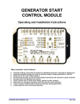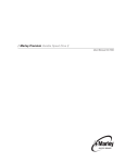
1
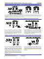
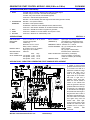
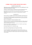
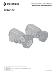
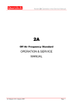
GENERATOR START CONTROL MODULE - MINI (2 Wire to 3 Wire)
GSCM-MINI
FEATURES & APPLICATIONS
v
v
v
v
v
v
v
Inexpensive 2 wire to 3 wire start controller for
electric start high speed gas generators.
Optimized for use with Outback Invertors.
Supports three types of 3 wire generator control
(momentary, maintained, ignition).
Fixed Crank time, Over and Under Hz shutdown
thresholds.
Optional Battery charging with fixed set points.
Remote Run and Fault indication included.
Totally sealed for harsh environment operation
DESCRIPTION
The GSCM-mini is a micro-processor based generator startstop module, designed to auto start-stop high speed gas
generators needing a 3 wire connection from a 2 wire
manual start command. It automatically disconnects the
starter when a minimum generator AC Hz. output is
measured, it can monitor the generator’s output, shutting
it down if either an over or under Hz condition is detected.
LEDs are flashed to indicate the cause of the shutdown.
Manually resetting the GSCM-mini by removing the power,
removes the lockout and allows the generator to restart if
called to do so. The GSCM-mini is powered by 12VDC
from the generator battery, and can monitor the battery
voltage and start the generator to charge it’s own battery.
All Thresholds are fixed. The GSCM-mini is a limited
function controller, part of the GSCM family. If adjustability
is required use the GSCM full function Generator Start
Control Module.
The GSCM-mini has six indication LEDs. The Start LED,
blinks every 5 seconds to indicate ready for a start signal,
blinks every 2.5 sec. to indicate running in Auto Start mode,
‘On’ continuously indicates running in Manual Start mode.
The Generator Hz LED, blinks to indicate over/under Hz Fault
and Start Failure do to Maximum crank attempted. A slow
blink indicates an under Hz condition, a fast blink indicates an
over Hz condition. ‘On’ continuously indicates AC present in
a non run condition. A double blink indicates a start failure
condition. The Run LED, ‘On’ continuously indicates a valid
Run signal from the generator. The Fault LED,‘On’ indicates
a Fault condition has occurred and GSCM is in lockout and
must be reset. The K1 and K2 LEDs indicate the relay status.
THREE MODES OF RELAY OPERATION
OPERATIONAL THRESHOLDS
The GSCM-mini’s two relay contacts can be configured for
three types of three wire start/stop hook-up configurations;
momentary, maintained and Ignition for Hondas, Onans,
Yamahas, and other brands of generators. This is
accomplished with an optional jumper on terminal 6.
The GSCM-mini has fixed operational thresholds. Those are:
Crank delay, Maximum Crank time, Crank Hz. Disconnect,
Under Speed Shutdown, Over Speed Shutdown, and auto
detects the Battery voltage to determine the auto start and
auto stop threshold values for 12V, 24V, and 48V battery
systems. If adjustability is required then use the GSCM full
function control module.
Momentary Start Contact Option #1, terminal 6, has No
Connection. The GSCM-mini defaults to a momentary crank
operation for those generators that use two momentary
push button switches to start and stop the generator. K1
cranks the Starter and K2 momentarily grounds the
magneto. See Section 1 for operation description.
Maintained Start Contact Option #2, terminal 6, is
grounded. The GSCM-mini changes to a maintained start
operation for generators that use a maintained closed
contact to start (K1). The generator is stopped by opening
K1 and closing K2 contact, momentarily grounding the
magneto. See Section 2 for operation description.
Ignition Key Switch Start Contact Option #3, terminal 6,
is connected to B+ (12VDC). The GSCM-mini simulates an
automobile ignition switch, K2 closes, maintains a closed
ignition contact for the generator to run and K1 closes
momentarily to crank the starter motor. and de-energizes
when the start signal is removed. The K1 relay operates in
a momentary crank configuration. See section 3 for
operation description.
LED INDICATION DESCRIPTION
Crank delay:
Maximum Crank:
Crank Disconnect:
Under Speed Shutdown:
Over Speed Shutdown:
Auto Start/Stop
Thresholds:
12V system
24V system
48V system
Start
11.5V
23.0V
46.0V
Stop
13.8V
27.6V
55.2V
Standard
Call for option
Call for option
Relay Configuration:: Open input = Momentary Crank
(TERMINAL 6)
Grounded input = Maintained Crank
B+ (12VDC) input = Ignition & Crank
Fault Detection:
ATKINSON ELECTRONICS, INC.
Web Site: www.atkinsonelectronics.com
5 seconds
20 seconds
45Hz
55Hz
65Hz
Start Failure, (3 attempts)
Over Hz condition (10 seconds)
Under Hz condition (10 seconds)
REV 9/05
Distributed by:
GENERATOR START CONTROL MODULE - MINI (2 Wire to 3 Wire)
GSCM-MINI
GSCM-mini WIRING DIAGRAM AND CONTROLLER CONFIGURATION
ATKINSON ELECTRONICS, INC.
Web Site: www.atkinsonelectronics.com
REV 9/05
Distributed by:
GENERATOR START CONTROL MODULE - MINI (2 Wire to 3 Wire)
GSCM-MINI
OPTION #1 MOMENTARY START CONTACT - TYPICAL GENERATOR W/ STARTER CONTROL BOX
The K1 relay is used to switch the start/crank input which is looking for a momentary signal and opens when the generator has
reached 50Hz, or half speed. The K2 relay provides a momentary “stop” signal until the generator AC Hz has dropped to zero.
For GSCM-mini operational sequence details see Page 4, Section - 1
OPTION #2 MAINTAINED START CONTACT TYPICAL GENERATOR W/ STARTER CONTROL BOX
The K1 relay provides a continuous run signal for
generators requiring a “maintained” start signal. The K2
relay provides a momentary “stop” signal until the generator
AC Hz has dropped to zero. For GSCM-mini operational
sequence details see Page 4, Section - 2
A double pole “kill switch” wired and installed by the user,
stops the generator instantly in emergency situations such as
a fuel spill. One switch pole (N.C.) kills power to the GSCMmini opening all relays. The other switch pole (N.O.) shorts
out the magneto for an instant stop.
OPTION #3 IGNITION KEY SWITCH TYPE START CONTACT TYPICAL GENERATOR W/ STARTER CONTROL
The K1 relay is used to switch the starter input which is
looking for a momentary signal and opens when the
generator has reached 50Hz, or half speed. The K2 relay
provides a continuous run signal for generators requiring a
“maintained” ignition signal. When the GSCM-mini no
longer receives a run command signal (terminal 5 or
batteries fully charged, K2 relay opens telling the generator
to shutdown. For GSCM-mini operational sequence details
see Page 5, Section - 3
A single pole “kill switch” wired and installed by the user,
stops the generator instantly in emergency situations such as
a fuel spill. One switch pole (N.C.) kills power to the GSCMmini opening all relays shutting down the ignition switch type
generators.
ATKINSON ELECTRONICS, INC.
Web Site: www.atkinsonelectronics.com
REV 9/05
Distributed by:
GENERATOR START CONTROL MODULE - MINI (2 Wire to 3 Wire)
GSCM-MINI
GSCM-mini MOMENTARY STARTING SEQUENCE (Relay Option #1)
SECTION - 1
The GSCM-mini indicates that it is ready to receive a start signal by blinking the start LED once every 5 seconds. The
CONFIGURATION terminal 6 has NO connection, configuring the GSCM-mini for momentary start sequence. The start signal
is created by closing a switch connected between the manual start terminal 5 to B+ terminal 3 or connecting the Aux + and Aux terminals form an Outback Inverter to terminal 5 (start) and terminal 7( ground). The module may also start in automatic mode
based on a battery voltage (see Section-6 for Automatic start for battery charging). If the GSCM-mini detects an AC signal from
the generator before a start command is given (ie: the generator is already running) it will not execute a start sequence until the
AC Hz. signal has been rectified, and will turn ON the Generator Hz LED. The generator starting sequence is as follows.
1.
The start LED blinks once every 5 seconds to indicate that the GSCM-mini is in a “Ready” mode. When a manual signal is
received, the start LED lights continuously. After a 2 second delay, K1 relay closes to crank the starter, and remains closed
until either the generator starts or the maximum cranking time period (20 seconds) is reached.
2. If the generator fails to start after the 20 seconds cranking period, K1 relay opens for a resting period of 40 seconds. The
K1 relay then closes again cranking the starter until the maximum cranking time is reached or the generator starts.
3. If the generator fails to start after 3 cranking attempts with the associated resting periods, then K2 relay closes for 5 seconds,
then the Gen Hz LED does a double blink, the Fault LED turns ON and the GSCM-mini enters the Max. Crank lockout
condition. This lockout condition remains until the GSCM-mini is reset by removing power from terminal 2 (see GSCM-mini
wiring diagram, previous page) and reconnecting power. The GSCM-mini will then clear the lockout condition, and enter
“Ready” mode with the Start LED blinking Every 5 seconds.
4. When the generator starts, K1 relay immediately opens, stopping the cranking. A valid run condition is determined by the
generator AC output frequency exceeding the crank disconnect setting of 45Hz and is indicated with the Run LED turned On..
5. If the generator starts but shuts down after a few seconds due to a fuel problem, etc. the start sequence will revert to the
“Ready” mode after a 60 second delay. During this delay the start LED will blink rapidly. The GSCM-mini will then try to start
the generator again in manual mode or after a 5 minute delay period in auto-start mode.
6. When a run condition is detected, the GSCM-mini turns ON the Run LED and transistor output (remote run lamp) and after
a 60 second generator stabilization period begins monitoring the AC Hz signal for over/under Hz condition.
7. If the generator starts but shuts down after the 60 seconds stabilization period, due to a fuel problem, etc. the GSCM-mini
blinks the Gen Hz LED for an Under Hz condition , after 60 seconds the Run LED turns Off, Fault LED turns On, and K2 relay
energizes for 5 seconds. The GSCM-mini enters a Fault shutdown lockout condition. A power down reset is required to clear
the lockout condition.
8. The generator continues running until one of the following occurs: the manual start signal is no longer received, the auto
battery charge voltage has been reached while running in Auto Charge Mode, an Over or Under Hz condition occurs (If Gen.
Hz. Shutdown is enabled) or the generator runs out of gas. (No run time limit)
9. During shutdown, K2 relay closes to ensure shutdown of the generator by grounding out the ignition, etc. It remains closed
until the AC Hz signal from the generator has gone to zero for 5 seconds ensuring that the generator has shutdown.
10. The generator remains off until another start signal is received.
GSCM-mini MAINTAINED STARTING SEQUENCE (Relay Option #2)
SECTION - 2
The CONFIGURATION terminal 6 has been connected to ground (terminal 7), configuring the GSCM-mini for maintained start
sequence. The GSCM-mini is then powered by connecting B+ (12.0 VDC) to terminal 2. After 10 seconds the GSCM-mini indicates
that it is ready to receive a start signal by blinking the start LED once every 5 seconds. The generator starting sequence is as
follows.
1.
2.
3.
4.
The start LED blinks once every 5 seconds to indicate that the GSCM-mini is in a “Ready” mode. When a manual start signal
is received, the start LED lights continuously. After a 2 second delay, K1 relay closes to start the generator. The K1 relay
remains closed until either the start signal is removed or the maximum cranking time of 1 minute is reached.
If the generator fails to start after a single 1 minute start period, GSCM-mini enters its Shutdown Routine, then the Gen Hz
LED does a double blink, the Fault LED turns ON and the GSCM-mini enters the Max. Crank lockout condition. This lockout
condition remains until the GSCM-mini is reset by removing power from terminal 2 (see GSCM-mini wiring diagram), and
reconnecting power. The GSCM-mini will then clear the lockout condition, and enter “Ready” mode with the Start LED
blinking Every 5 seconds.
When the generator starts, K1 relay remains energized. A valid run condition is determined by the generator AC output
frequency exceeding the crank disconnect setting of 45Hz and is indicated by the Run LED being turned ON.
If the generator starts but shuts down after a few seconds due to a fuel problem, etc. The GSCM-mini goes thru it’s Shutdown
Routine then re-enters “Ready” mode after a 60 second delay. During this delay the start LED will blink rapidly. The GSCMmini will then try to start the generator again in manual mode or after a 5 minute delay period in auto-start mode.
ATKINSON ELECTRONICS, INC.
Web Site: www.atkinsonelectronics.com
REV 9/05
Distributed by:
GENERATOR START CONTROL MODULE - MINI (2 Wire to 3 Wire)
GSCM-MINI
GSCM-mini MAINTAINED STARTING SEQUENCE continued
SECTION - 2
5.
6.
7.
8.
9.
When a run condition is detected, the GSCM-mini turns ON the Run LED and open collector transistor output (remote run
lamp) and after a 60 second generator stabilization period begins monitoring the AC Hz signal for over/under Hz condition.
If the generator starts but shuts down after the 60 seconds stabilization period, due to a fuel problem, etc. the GSCM-mini
blinks the Gen Hz LED for an Under Hz condition , after 60 seconds the Run LED turns Off, Fault LED truns On, and K2 relay
energizes for 5 seconds. The GSCM-mini enters a Fault shutdown lockout condition. A power down reset is required to clear
the lockout condition.
The generator continues running until one of the following occurs: the manual start signal is no longer received, the auto
battery charge voltage has been reached while running in Auto Charge Mode, an Over or Under Hz condition occurs (If Gen.
Hz. Shutdown is enabled) or the generator runs out of gas. (No run time limit)
Shutdown Routine, K1 de-energizes, then ½ second later K2 relay energizes , remains closed until the AC Hz signal from
the generator goes to zero for 5 seconds ensuring generator shutdown.
The generator remains off until another start signal is received.
GSCM-mini IGNITION/CRANK STARTING SEQUENCE (Relay Option #3)
SECTION - 3
The CONFIGURATION terminal 6 has been connected to B+ (terminal 3), configuring the GSCM-mini for ignition/crank start
sequence. The GSCM-mini is then powered by connecting B+ (+12 VDC) to terminal 2. After 5 seconds the GSCM-mini indicates
that it is ready to receive a start signal by blinking the start LED once every 5 seconds. The starting sequence is as follows.
1.
The start LED blinks once every 5 seconds to indicate that the GSCM-mini is in a “Ready” mode. When a manual signal is
received, the start LED lights continuously. After a 2 second delay, K2 relay energizes and remains energized until the start
signal is either removed or the generator fails to start after 3 attempts. K1 relay closes to crank the starter. The K1 relay
remains closed until either the generator starts or the maximum cranking time period (20 seconds) is reached.
2. If the generator fails to start after the 20 seconds cranking period, K1 relay opens for a resting period of 40 seconds. The
K1 relay then closes again cranking the starter until the maximum cranking time is reached or the generator starts.
3. If the generator fails to start after 3 cranking attempts with the associated resting periods then K2 relay de-energizes and
the GSCM-mini enters its Shutdown Routine, then the Gen Hz LED does a double blink, the Fault LED turns ON and the
GSCM-mini enters the Max. Crank lockout condition. This lockout condition remains until the GSCM-mini is reset by removing
power from terminal 2 (see GSCM-mini wiring diagram) and reconnecting power. The GSCM-mini will then clear the lockout
condition, and enter “Ready” mode with the Start LED blinking Every 5 seconds.
4. When the generator starts, K1 relay immediately opens, stopping the cranking. A valid run condition is determined by the
generator AC output frequency exceeding the crank disconnect setting of 45Hz.
5. If the generator starts but shuts down after a few seconds due to a fuel problem, etc. the start sequence will revert to the
“Ready” mode after a 60 second delay. During this delay the start LED will blink rapidly. The GSCM-mini will then try to start
the generator again in manual mode or after a 10 minute delay period in auto-start mode.
6. When a run condition is detected, the GSCM-mini turns ON the Run LED and open collector transistor output (remote run
lamp) and after a 60 second generator stabilization period begins monitoring the AC Hz signal for over/under Hz condition.
7. If the generator starts but shuts down after the 60 seconds stabilization period, due to a fuel problem, etc. the GSCM-mini
blinks the Gen Hz LED for an Under Hz condition , after 60 seconds the Run LED turns Off, Fault LED turns On, and K2 relay
energizes for 5 seconds. The GSCM enters a Fault shutdown lockout condition. A power down reset is required to clear the
lockout condition.
8. The generator continues running until one of the following occurs: the manual start signal is no longer received, the auto
battery charge voltage has been reached while running in Auto Charge Mode, an Over or Under Hz condition occurs (If Gen.
Hz. Shutdown is enabled) or the generator runs out of gas. (No run time limit)
9. When the manual start signal is removed, K2 relay de-energizes opening the ignition circuit shutting down the generator. The
GSCM-mini then monitors the Generator AC Hz input to watch for a zero Hz condition before returning to “Ready” mode. If
the AC signal remains the GSCM-mini’s Generator HZ LED turns on indicating AC Hz. Signal still present and will not return
to Ready mode until the AC signal goes to zero. Once it goes to zero the GSCM-mini returns to “Ready’ mode.
10. The generator remains off until another start signal is received.
GSCM-mini WITH A MANUAL/OFF/AUTO SWITCH OPTIONS
SECTION - 4
The Manual start signal is created by connecting terminal 5 (man. Start) to terminal 3 (B+12VDC) through a Power/Reset Switch
(see GSCM-mini wiring diagram). It may also be generated by an Outback Inverter using the AUX+/- connections on the remote
terminal block. The Outback provides a switched +12VDC signal for the GSCM-mini’s manual start input. An optional Manual-OffAuto switch can be installed to provide user flexibility for manual starts, resets, turning the unit off, or Auto starting from Inverter.
(see GSCM-mini’s wiring diagram, lower right hand corner).
ATKINSON ELECTRONICS, INC.
Web Site: www.atkinsonelectronics.com
REV 9/05
Distributed by:
GENERATOR START CONTROL MODULE - MINI (2 Wire to 3 Wire)
GSCM-MINI
GSCM-mini FAULT SHUTDOWN CONDITIONS
SECTION - 5
The GSCM-mini detects three (3) fault shutdown conditions (over/under Hz. detection not enabled until the generator has been
running for 60 seconds) and will shutdown the generator after 10 continuous seconds of Hz. fault condition, locking it out until a
power down reset and power back up. The Fault open collector transistor output (terminal 12) will energize a user supplied
remote lamp or DC relay (not exceeding 300 milliamp coil current) whenever a fault shutdown occurs and will de-energize the relay
when the fault is reset. The shutdown conditions are as follows:
1.
2.
3.
Failure to start with 3 cranking attempts (see Section-1:3, 2:2, & 3:3 ). The Gen. Hz Shutdown LED does a double blink and
Fault LED On continuously.
High frequency (over Hz.) condition. The generator AC frequency is monitored on terminals 9 and 10. If the Gen. Hz. enable
terminal #8 is grounded and the generator output frequency exceeds the 65 Hz fixed threshold for 10 seconds, the generator
shuts down and the Generator Hz shutdown LED blinks rapidly. The “Generator Hz” LED blinks during this 10 second period.
Low frequency (under Hz.) condition. If the Gen. Hz. enable terminal #8 is grounded and the generator output frequency
remains below the 55 Hz fixed threshold for 10 seconds, the generator shuts down and the Generator Hz shutdown fault LED
blinks slowly. The “Generator Hz” LED blinks during this 10 second period.
AUTOMATIC STARTING FOR BATTERY CHARGING
SECTION - 6
The GSCM-mini can monitor either the generator battery voltage or a battery bank voltage and Automatically start/stop the
generator based on battery voltage. This is accomplished by connecting the battery voltage to the battery sense input (terminal
4). The GSCM-mini monitors a battery voltage range of 0 to 60V DC and automatically determines the start and stop set point
based on battery voltage (12, 24, or 48VDC). Below 16VDC - 12V thresholds, between 16 to 32V - 24V thresholds, above 32V 48V thresholds. This mode is disabled if the voltage on terminal 4 is less than 6V, (no connection).
1.
2.
3.
4.
5.
The GSCM-mini monitors the battery sense input and when the battery voltage drops below the start threshold the Start LED
begins blinking (three fast blinks with 2 second off time). When the battery sense voltage has remained below the start
threshold for 5 continuous minutes the Auto start sequence begins. If the battery voltage rises above the start threshold
during the 5 minute period the 5 minute timing cycle starts over. (Temporary battery voltage fluctuations such as
instantaneous inverter loads will not start the GSCM.) The start LED blinks every 3 seconds while the GSCM-mini is running
the generator in auto-start battery charging mode.
The GSCM-mini starts the generator as described in sections 1: momentary start, 2: maintained start, or 3: ignition start.
The GSCM-mini shuts down the generator (as described in Sections 1, 2, or 3) whenever the battery voltage exceeds the stop
threshold for 10 minutes. The Start LED blinks (three fast blinks with 2 second off time) during this 10 minute period. The
GSCM-mini will exit the 10 minute period and shutdown the generator if the battery voltage exceeds the stop point by +1.0V
(for a 12V system, 2V for 24V system, voltages are proportional). The generator remains off until the battery voltage drops
below the start threshold voltage.
There is no maximum runtime shutdown in either manual or auto start.
If the user wishes to manual-start the generator from a separate pressure switch, level switch, thermostat or inverter start
contact, etc., the battery voltage is fed through the switch (pressure switch etc.) contact to Manual start terminal 5. Closing
the contact will cause the GSCM-mini to start the generator. Some invertors provide a switch 12VDC signal to start the
generator. This switched voltage can be connected directly to the manual start terminal 5 and ground terminal 7. (See GSCMmini wiring diagram for hook-up).
GENERATOR EMERGENCY SHUTDOWN WITH THE GSCM-mini
SECTION - 7
The GSCM-mini Generator Start Stop module is NOT AN EMERGENCY SHUTDOWN DEVICE!! If the manual start signal is
removed the generator will go through a normal shutdown which may take up to 15 seconds to completely shutdown the generator
A RECOMMENDED EMERGENCY SHUTDOWN SOLUTION is to install a separate “Kill” switch and label it as such. The
recommended wiring is shown on page-2 of these instructions and also in Application 1. Disconnecting the power to the GSCMmini module will force the relays to open. This will shutdown generators that require a maintained run signal from K1 relay.
However this also prevents the K2 relay from closing to shutdown those generators requiring a momentary stop signal. Using
a double pole “Kill” switch and wiring the second pole in parallel with the K2 relay terminals will force the generator to stop in an
emergency situation such as a fuel spill. (see note 1 on wiring diagram, page 2, for Ignition/crank emergency shutdown option).
ATKINSON ELECTRONICS, INC.
Web Site: www.atkinsonelectronics.com
REV 9/05
Distributed by:
GENERATOR START CONTROL MODULE - MINI (2 Wire to 3 Wire)
GSCM-MINI
LED DESCRIPTION (WHAT THEY MEAN)
SECTION - 8
1.
Start:
one blink every 5 seconds = Ready mode, looking for a start signal;
one blink every 2.5 seconds = auto start mode operation;
one blink every other second= auto start/stop period,
continuous = manual start signal received;
fast blink = 60 second delay after start signal removed before generator started;
2.
Generator Hz
Shutdown:
fast blink = over speed condition;
slow blink = under speed condition;
double blink = Maximum Crank attempts reached, Failed to Start;
continuous = start function disabled, AC Hz detected before starting;
3.
4.
5.
Run:
Fault:
K1 & K2:
continuous = GSCM has a valid run signal from generator;
continuous = GSCM is in a fault condition and requires a reset;
continuous = Status of K1 and K2 Relays “ON”
SPECIFICATIONS
SIZE & WEIGHT:
MOUNTING:
POWER:
SECTION - 9
5.13" L x 2.853" W x 1.35" H, 20 OZ
2 screws through tabs
12VDC only
Quiescent current < 10mA
Relay current < 25mA ea.
MANUAL INPUT:
B+ (12VDC) input = on condition
Open input = off condition
BATTERY INPUT:
0-60V DC
AUTO START/
Start
Stop
STOP THRESHOLD: 12V System 11.5V, 13.5V
24V System 23.0V, 27.0V
48V System 46.0V, 54.0V
RELAY CONFIG.:
(TERMINAL 6)
Open input = Momentary Crank
Grounded input = Maintained Crank
B+ (12VDC) input = Ignition & Crank
FREQUENCY INPUT: 120-240V AC 0-100 Hz
OUTPUT RATINGS: Qty. (2) 10 Amp 28V DC, 240V AC
Relay contacts
Qty. (2) Open collector NPN
transistors, Max. 300mA each
FAULT DETECTION: Start Failure, (3 attempts)
Over Hz condition (10 seconds)
Under Hz condition (10 seconds)
AMBIENT TEMP:
-40 to 858C
APPLICATION 2 - REMOTE RV GENERATOR START CONSOLE REPLACEMENT
The GSCM mini can be used
to replace a typical remote
generator control console, that
is mounted on the dash of a
motorhome. Instead of a large
console and cable, use a
small 16 to 18 gauge 4 wire
signal cable, an on-off switch
with built in light and a
separate 12vdc fault light.
When the remote switch is
turned on, the GSCM mini
starts the generator. After the
generator starts and comes up
to speed the “run” LED lights
on the GSCM mini and lights
the remote start switch light. If
the generator fails to start or
fails while commanded to run
the “fault” LED on the GSCM
mini lights along with the
remote fault 12vdc light.
Turning off the power to the
GSCM mini resets the fault
condition and it is ready to
receive
another
start
command.
ATKINSON ELECTRONICS, INC.
Web Site: www.atkinsonelectronics.com
REV 9/05
Distributed by:
GENERATOR START CONTROL MODULE - MINI (2 Wire to 3 Wire)
GSCM-MINI
LIMITED WARRANTY
Atkinson Electronics, Inc. gives this express warranty (along with extended warranty endorsements, where applicable)
in lieu of all other warranties, express or implied, including (without limitation), warranties of merchantability and fitness
for a particular purpose. This constitutes Atkinson Electronics, Inc.'s sole warranty and obligation with regard to our
products as well as the Customer's sole remedy.
Atkinson Electronics, Inc. expressly disclaims all liability and responsibility for any special, indirect or consequential
damages or any further loss of any kind whatsoever resulting from the use of our product. The Customer's sole and
exclusive remedy and the limit of Atkinson Electronics, Inc.'s liability for any loss whatsoever, shall not exceed the
purchase price paid by the Customer for the product to which a claim is made.
Countries or States that do not allow limitations of incidental or consequential damages or on how long an implied
warranty lasts, the above limitations may not apply to you. This warranty gives you specific legal rights and you may
also have other rights which vary from State to State or Country to Country.
All products manufactured by Atkinson Electronics, Inc. are warranted to be free from defects in material and
workmanship in accordance with and subject to the following terms and conditions:
1. This warranty is limited to the original customer only. It cannot be transferred or assigned to third parties unless
the intent to transfer to a third party is expressly indicated in a purchase order and/or warranty processing
arrangements have been agreed upon in writing by Atkinson Electronics, Inc.
2. Atkinson Electronics, Inc. will correct any defects in material or workmanship which appear within two (2) years
from the date of shipment by Atkinson Electronics, Inc. (or its authorized distributors) to the original Customer.
Atkinson Electronics, Inc. will repair or replace, at our option, any defective products, provided that our inspection
discloses that such defects developed under normal and proper use. This warranty does not extend to goods
subjected to misuse, neglect, accident or improper installation, or to maintenance or repair of products which have
been altered or repaired by anyone except Atkinson Electronics, Inc., unless otherwise stated in writing.
Atkinson Electronics, Inc. will correct any defects in material or workmanship of OEM products (designated as
such in our catalog or web site) which appear within two (2) years from the product date code or from the factory
invoice date, whichever is later.
3. An appropriate charge (25% of product list price) may be made for testing, repairs, replacement and shipping for
a returned product which is not defective or found to be defective as the result of improper use, maintenance or
neglect.
4. Atkinson Electronics, Inc. will not accept responsibility for any invoiced goods or services that are not covered by
an Atkinson Electronics, Inc. written purchase order. Under no circumstances does Atkinson Electronics, Inc.
agree to pay for labor or other related expenses associated with the troubleshooting and/or repair of our product
without prior specific written authorization.
5. Information in our descriptive literature is based on product specifications that are current at the time of
publication. Product specifications, design and descriptive literature are subject to change as improvements are
introduced. Although we announce changes as they occur, we cannot guarantee notification to every Customer.
Atkinson Electronics, Inc. warrants delivered products to conform to the most current specifications, design and
descriptive literature.
This warranty policy may be expanded or limited, for particular categories of products or Customers, by information
sheets published as deemed appropriate by Atkinson Electronics, Inc.
ATKINSON ELECTRONICS, INC.
Web Site: www.atkinsonelectronics.com
REV 9/05
Distributed by: