1
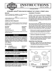
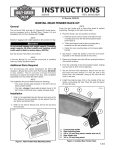
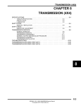
INSTRUCTIONS
REV. 8-16-01
-J02268
®
Kit Number 18088-02
CHROME BILLET LIFTER-COVER KIT
General
1WARNING
This kit fits all 1999 and later Twin Cam 88 engines.
Kit contents:
QTY
1
1
2
8
DESCRIPTION
Front chrome billet lifter cover
Rear chrome billet lifter cover
Lifter-cover gaskets
Socket-head cap screws, chrome
PART NO.
18089-02
18091-02
18635-99A
94314-91T
1WARNING
A Service Manual is required to install this kit. The rider's
safety depends upon the correct installation of this kit. If
the procedure is not within your capabilities or you do not
have the correct tools, have your Harley-Davidson dealer
perform the installation. Improper installation of this kit
could result in death or serious injury.
NOTE
A Service Manual for your model motorcycle is available
from your Harley Davidson Dealer.
Always disconnect the negative battery cable first. If the
positive battery cable should contact ground with the
negative cable installed, the resulting sparks may cause
a battery explosion which could result in death or serious personal injury.
Installation with Stock Pushrods
Refer to the service manual for your motorcycle model.
Installation with Adjustable Pushrods
Lifter-Cover Removal
CAUTION
Installing or removing the pushrods with the valve train
loaded can result in engine damage. On the cylinder
being serviced, always set the lifters to the base circle
on the cam before servicing pushrods, lifters, rocker
arms, and valves.
This kit installs in one of two ways, depending upon the kind
of pushrods to be installed with the chrome billet lifter-cover
kit. If you are installing:
1.
Set the lifters of the rear cylinder to their lowest point, or
base circle, on the cam. Refer to Setting the Lifters to
the Base Circle in this instruction sheet.
• stock pushrods with the chrome billet lifter-cover kit,
refer to the service manual for your motorcycle model.
2.
See Figure 1. Insert a screwdriver into the slot on the
side of the spring-cap retainer on the pushrod cover.
• Screamin’ Eagle adjustable pushrods with the chrome
billet lifter-cover kit, refer to Installation with Adjustable
Pushrods in this instruction sheet.
i04190
NOTE
Harley-Davidson recommends replacing the pushrod-cover
O-rings with O-ring part numbers 11293 (top), 11132 (middle) and 11145 (bottom) during lifter-cover installation and
assembly.
NOTE
Installing an adjustable pushrod kit may void the HarleyDavidson limited warranty.
CAUTION
Solid lifters must not be installed with the stock
camshaft. Severe engine damage may result.
1WARNING
To protect against shock and accidental start-up of the
vehicle, disconnect the negative battery cable before
proceeding. Inadequate safety precautions could result
in death or serious injury.
Figure 1. Pushrod Cover Removal
3.
Press the spring-cap and retainer down while pulling
outward to remove the spring-cap retainer.
4.
See Figure 2. Lift the lower pushrod cover to reveal the
lower third of the pushrod.
5.
If the engine has stock pushrods installed and you are
installing adjustable pushrods with this lifter-cover
installation, go to step 6. If the engine already has
adjustable pushrods installed and you are installing
adjustable pushrods with this lifter-cover installation, go
to step 7.
1 of 3
Lifter-Cover Installation
1
i04187
1.
2
See Figure 3. Verify that the lifter anti-rotation pin is in
position.
i04188
15
3
4
Anti-rotation
pin
5
6
7
8
9
14
10
Figure 3. Lifter Anti-Rotation Pin
11
CAUTION
12
13
Item
1
2
3
4
5
6
7
8
Description
O-ring
Pushrod upper
cover
Spring-cap
retainer
Spring cap
Spring
Washer
O-ring
Pushrod lower
cover
Item
9
10
11
12
13
14
15
Description
O-ring
Lifter cover
Lifter anti-rotation
pin
Gasket
Lifter
Screw
Pushrod
Figure 2. Pushrod, Pushrod Cover, and Lifter Cover
6.
Use a bolt cutter or similar tool to cut the stock pushrod.
Avoid cutting the pushrods with a saw, grinder, or other
method that may allow metal debris into the engine. Go
to step 8.
7.
Loosen the jam nut on each adjustable pushrod and
resize each rod to its shortest length.
8.
Remove the pushrod covers and pushrods from the
engine.
9.
Remove the O-rings from the seats in the engine at the
top and bottom of the pushrod cover.
Installing or removing the pushrods with the valve train
loaded can result in engine damage. On the cylinder
being serviced, always set the lifters to the base circle
on the cam before servicing pushrods, lifters, rocker
arms, and valves.
2.
Verify that the cylinder lifters are set to their lowest
point, or base circle, on the cam. Refer to Setting the
Lifters to the Base Circle in this instruction sheet.
3.
Fasten the new lifter-cover gasket and chrome billet
lifter cover to the engine using the chrome screws from
this kit. In a cross pattern, torque the lifter-cover screws
to 90 – 120 in-lbs (10.2 – 13.6 Nm).
4.
See Figure 4. Loosen the jam nut on all of the pushrods
and adjust the pushrods to their shortest length.
NOTE
See Figures 4 and 5. Install the narrow-band pushrods in the
cylinder-intake location. Install the wide-band pushrods in the
cylinder-exhaust location.
5.
Assemble the O-rings (purchased separately) and
pushrod covers.
6.
Install the pushrods with the pushrod covers. The
adjustment-end of the pushrod must be on the lifter.
NOTE
Do not install the spring-cap retainers on the pushrod covers
at this time.
7.
To adjust pushrods on hydraulic lifters, go to step 8. To
adjust pushrods on solid lifters, go to step 11.
10. Remove the four screws fastening the lifter cover to the
engine to remove the cover and gasket.
NOTE
Pushrod adjustment must be made with the engine cold.
11. Remove old lifter-cover gasket material from the engine,
taking care not to allow material to fall into the engine.
Continue to Lifter-Cover Installation in this I-Sheet.
8.
-J02268
See Figure 4. Adjust each pushrod length to zero
clearance.
• Use a wrench to keep the pushrod from rotating.
2 of 3
• Slowly turn the adjusting screw 2-1/2 complete turns
(lengthening the pushrod).
9.
i04189
Hold the adjusting screw and tighten the jam nut against
the pushrod. If the pushrod turns with the jam nut, use
three wrenches; one to hold the pushrod, one to hold
the adjusting screw, and one to turn the jam nut.
2
3
1
i02097
Intake
Pushrod is
shorter, has
narrow band
Exhaust
Pushrod is
longer, has
wide band
4
1.Rear cylinder exhaust
2.Rear cylinder intake
3.Front cylinder intake
4.Front cylinder exhaust
Figure 5. Pushrod Locations and Functions
NOTE
Check for contact between the pushrods and upper pushrod
covers. Rotate the engine slowly until both valves are closed
on the cylinder you are checking. If contact occurs, shift the
rocker arm supports toward the engine’s cam side.
14. Install the pushrod spring-cap retainers on the pushrod
covers.
Adjustingscrew flats
15. Install the spark plugs and plug wires, and shift the
transmission to neutral.
Jam nut
Adjusting screw
Figure 4. Adjustable Push Rod
1WARNING
Always connect the positive battery cable first. If the
positive cable should contact ground with the negative
cable installed, the resulting sparks may cause a battery
explosion which could result in death or serious injury.
16. Connect the battery cables.
CAUTION
Wait ten minutes before turning engine over after
adjusting front or rear cylinder pushrods. This allows
lifters to bleed down and prevents bending the
pushrods and valves. Pushrods should turn freely and
valves must be seated before turning over the engine.
Setting the Lifters to the Base Circle
This procedure positions both lifters of a cylinder to their
lowest position on the cam, reducing valve-spring pressure
to a minimum. This procedure is required for removing and
installing a rocker-arm support plate on a cylinder.
1.
Remove the spark plugs from the engine.
2.
Elevate the motorcycle on a center stand until the rear
wheel is elevated from the ground.
3.
Shift the transmission into 5th gear.
4.
From the left side of the motorcycle, put a left-hand
finger over the spark-plug hole on a cylinder.
10. Wait ten minutes. Go to step 13.
11. See Figure 4. Adjust each pushrod length to zero
clearance. The pushrod must turn with no drag and no
vertical play.
12. Hold the adjusting screw and tighten the jam nut against
the pushrod. If the pushrod turns with the jam nut, use
three wrenches; one to hold the pushrod, one to hold
the adjusting screw, and one to turn the jam nut.
13. Repeat Lifter-Cover Removal steps 1 – 11 and LifterCover Installation steps 1 – 7 for the front cylinder.
When both cylinders’ pushrods are installed, go to step
14.
-J02268
• Turn the rear wheel counterclockwise with your right
hand until you feel the compression stroke of the
piston forcing air out of the spark-plug hole.
• When air pressure through the spark-plug hole stops,
the piston is at top-dead-center (TDC). Stop turning
the rear wheel and check TDC with a flashlight beam
directed into the spark-plug hole.
• If the piston is at TDC on the compression stroke and
the lifters are in their lowest position on the cam, then
the intake and exhaust valves are closed and the
pushrods are unloaded, and the rocker-arm support
plate can be safely removed or installed.
3 of 3