1
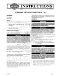
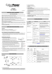
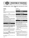
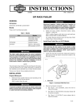
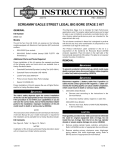
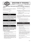
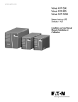
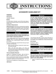
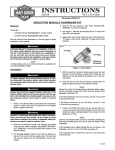
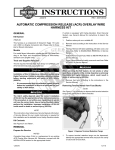
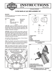
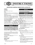
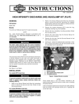
INSTRUCTIONS
®
REV. 07-13-2005
-J03817
Kit Number 29791-05
SCREAMIN’ EAGLE® TWIN-CAM 203 CAMSHAFT KIT, STAGE II, STREET LEGAL
Installation Procedure
General
This kit is designed for installation on 2005 Model Year
1550cc Anniversary Edition FLSTFI motorcycles.
NOTE
A Service Manual for your motorcycle is available from your
Harley-Davidson Dealer.
Additional Parts Required
Installation of the camshafts included in this kit requires the
separate purchase of the following kits from your HarleyDavidson Dealer:
Description
Spacer Kit
Part Number
25938-00)
Cam Service Kit
17045-99B
Drive Gear Retention Kit
25533-99A
1999 Models will require the purchase of Splined Cam Drive
Sprocket, 25716-99.
1WARNING
Kit Contents
Description
S.E. 203 camshaft, front
S.E. 203 camshaft, rear
NOTE
Both crank and primary cam sprocket flange bolts are specially hardened while the flat washers are of a special diameter and have ground surfaces. Therefore, use only the
parts provided in the Drive Gear Retention Kit (Part Number
25533-99A) when performing this upgrade. The crank and
primary cam sprocket flange bolts are NOT interchangeable.
1. Remove crank and primary cam sprocket flange bolts
and washers according to applicable Service Manual.
Discard cam drive sprocket flange bolts and washers.
2. Remove existing cam drive sprocket according to
instructions in applicable Service Manual.
The rider’s safety depends upon the correct installation
of this kit. Use the appropriate service manual procedures. If the procedure is not within your capabilities or
you do not have the correct tools, have a HarleyDavidson dealer perform the installation. Improper
installation of this kit could result in death or serious
injury. (00333a)
Qty
1
1
Installation of this kit requires removal and re-installation of
the cam support plate. Refer to Section 3, ENGINE,
BOTTOM END, Cam Support Plate, Removal and
Disassembly/Assembly (Camshaft, Camshaft Bearings) of
the applicable Service Manual for instructions. Replace
information pertaining to cam compartment components with
the following information:
Part Number
not sold
not sold
1WARNING
3. Remove cam bearings according to ENGINE, BOTTOM
END, Cam Support Plate, Disassembly/Assembly
(Camshaft, Camshaft Bearings) instructions in applicable Service Manual. Discard cam bearings.
Install New Cam Bearings
1. See Figure 1. Obtain new Rear Cam Roller Bearing Kit
(Part Number 8983) from Cam Service Kit (Part Number
17045-99B) and install according to the following:
2. Install O-ring (1), thrust washer (2), and bearing inner
race (3) onto rear camshaft as follows:
i02061
To prevent accidental vehicle start-up, which could
cause death or serious injury, disconnect negative battery cable before proceeding. (00048a)
2
1
1WARNING
To prevent accidental vehicle start-up, which could
cause death or serious injury, disconnect battery cables
(negative cable first) before proceeding. (00307a)
1WARNING
When servicing the fuel system, do not smoke or allow
open flame or sparks in the vicinity. Gasoline is
extremely flammable and highly explosive, which could
result in death or serious injury. (00330a)
4
1.
2.
3
O-ring
Thrust washer
3.
4.
Bearing inner race
Roller bearing
Figure 1. Rear Cam Roller Bearing Kit
(Part Number 8983)
1 of 4
a. To properly locate thrust washer (2), first install O-ring
(1) in grinding relief groove. Groove is on the splined
end between the machined area and the secondary
cam sprocket. Exercise caution to avoid stretching or
breaking the O-ring. Since the O-ring is not sold
separately, damage will require purchase of new roller
bearing kit.
3. Install new cam bearings into cam support plate according to the following:
i02063
2
1
CAUTION
The thrust washer will be offset to one side if the O-ring
is not installed in the grinding relief groove. Damage to
the bearing cage can occur if the thrust washer is not
properly centered.
b. Slide thrust washer (2) down rear camshaft until
centered over O-ring (1) in grinding relief position.
1.
2.
Rear cam, roller bearing
Front cam, ball bearing
Figure 3. Cam Bearings
c. Slide bearing inner race (3) down rear camshaft until
contact is made with shoulder of machined area.
d. Install primary cam sprocket spacer and sprocket on
camshaft and secure using thicker flat washer and
long flange bolt.
NOTE
If not enough of the splined shaft is exposed to install the
sprocket, leave out the spacer and proceed to Step 2(e).
Once the bearing inner race (3) has been started onto the
machined area, remove the flange bolt, washer and sprocket, then re-assemble using the spacer. Repeat Step 2(e) to
fully install bearing inner race.
NOTE
See Figure 3. Be aware that the front and rear cam bearings
are no longer interchangeable. The rear bearing (1) is now the
roller type, while the front bearing (2) remains the ball type.
i02064
3
i02062
1
2
4
Box wrench, 9/16 in.
Inner race
3.
4.
2
3
1.
2.
1.
2.
1
Thrust washer
Shop rag
Figure 2. Install Bearing Inner Race
(with O-Ring and Thrust Washer)
e. See Figure 2. Wrap a shop rag (4) around camshaft
to get a firm grip and also to protect hand from sharp
edges of sprocket. Using a 9/16 in. box wrench (1),
turn flange bolt in a clockwise direction. Bearing inner
race (2) is fully installed when it makes firm contact
with the thrust washer (3).
f. Verify that thrust washer (3) is locked in place and
cannot be rotated. If necessary, install shaft in vise
using brass jaw inserts, and further tighten flange
bolt until the desired result is achieved.
Support block
Bearing pilot/driver
3.
Camshaft driver
Figure 4. Camshaft/Camshaft Bearing Remover/Installer
(Part Number HD-43644)
a. See Figure 4. Obtain the CAMSHAFT/CAMSHAFT
BEARING REMOVER/INSTALLER (HD-43644).
NOTE
Bearings may be a press to loose fit. If deemed necessary,
clean bearing OD and apply Loctite® Low Strength
Threadlocker 242 (blue) before installation, but exercise
caution to avoid getting compound on rollers or bearing ID.
b. With the secondary cam chain side facing upward,
place cam support plate on support block (1), so that
outer races of bearings are properly supported. Note
that one corner of the support block (1) is contoured
to accommodate the chain guide blocks cast into the
front of the support plate.
g. Remove flange bolt, flat washer, sprocket and
spacer.
-J03817
2 of 4
c. Center new bearing over bearing bore with the
lettered side up. Slide pilot shaft of bearing driver (2)
through bearing into hole of support block (1).
i02066
2
1
i02065
2
1
3
3
1.
2.
Bearing pilot/driver
Bearing
3.
Support block
Figure 5. Press Bearings into Cam Support Plate
d. See Figure 5. Center bearing driver (1) under ram of
arbor press. Press on driver until bearing (2) makes
firm contact with counterbore in cam support plate.
Repeat steps to install second bearing.
4. Apply a small amount of Loctite Medium Strength
Threadlocker 243 (blue) to threads of four bearing
retainer plate screws. Using a T20 TORX drive head,
secure bearing retainer plate to cam support plate.
Tighten screws to 20-30 in-lbs (2.3-3.4 Nm) in a crosswise pattern.
5. Place cam support plate back on support block (3), if
removed. The block properly supports inner races of
bearings as camshafts are installed.
1.
2.
Camshaft, rear
Camshaft, front
3.
Punch marks
Figure 6. Align Punch Marks on Teeth of Camshaft
Sprockets
6. See Figure 6. Align punch marks (3) on teeth of
secondary cam sprockets (outboard faces). Using a
colored marker, carefully mark the punch mark (3)
locations on the inboard side of the sprocket teeth.
These marks are needed to observe proper orientation
of the camshafts when they are pressed into the
bearings.
7. Place the secondary cam chain around the sprockets of
both the front (2) and rear (1) camshafts. To maintain
the original direction of rotation, be sure that the colored
mark placed on the chain link during disassembly is
facing opposite the cam support plate during
installation.
8. Orient the camshafts so that they are positioned on
opposite ends of the chain, and then verify that the
colored marks placed on the inboard side of the
sprocket teeth are still in alignment.
9. Maintaining the position of the camshafts on the chain
with the colored marks in alignment, place the sprocket
ends of the camshafts into the bearings.
NOTE
Be sure not to mix camshafts during the press procedure.
The rear camshaft, which can be identified by the splined
shaft, must go into the roller bearing at the rear of the cam
support plate.
10. Place cup of camshaft driver over end of front camshaft
only.
CAUTION
Be sure that tensioner shoe is clear of the secondary
cam chain during the press procedure. Contact can
result in damage that requires replacement of the tensioner assembly.
11. Center end of front camshaft under ram and slowly
apply pressure to driver just to start front camshaft into
bearing ID.
-J03817
3 of 4
1WARNING
CAUTION
If rear camshaft is not properly aligned, edge of installed
inner race can catch on bearing rollers. Bearing damage
can result if contact occurs during the press procedure.
12. Slowly apply pressure to driver on front camshaft, while
wiggling rear camshaft as necessary to guide inner race
between bearing rollers.
Failure to use Loctite 262 (red) may result in a joint that
will not maintain proper clamp load and may loosen
under certain circumstances, causing engine failure,
which could result in death or serious injury.
c. Apply a thin film of clean H-D 20W50 engine oil to
both sides of flat washers.
13. When inner race on rear cam is started into roller
bearing, apply pressure to driver until front camshaft is
fully seated. If necessary, keep finger pressure at top of
rear camshaft to ensure that assembly remains square
and inner race moves to installed position in roller
bearing.
d. Start flange bolt with flat washer to secure crank
sprocket to end of crankshaft.
e. Start flange bolt with flat washer to secure primary
cam sprocket to end of camshaft.
i02067
14. After installing new cams, check for proper cam-to-cam
timing using straightedge along punch marks as
described in Service Manual.
15. Install new retaining ring in groove at end of front
camshaft.
NOTES
Replace original oil pump to cam plate O-ring with new Oring (Part Number 11286) from Service Kit (Part Number
17045-99B).
Replace original cam plate to crankcase O-ring with new
O-ring (Part Number 11301) from Service Kit (Part
Number 17045-99B).
1
16. Install cam plate according to ENGINE, BOTTOM END,
Cam Support Plate, Disassembly/Assembly instructions
in applicable Service Manual.
1.
17. Apply a thin film of clean H-D 20W50 engine oil to the
splines of the rear cam.
Figure 7. Crankshaft/Camshaft Sprocket Locking Tool
(Part Number HD-42314)
18. Install splined sprocket onto rear camshaft according to
ENGINE, BOTTOM END, Cam Support Plate,
Disassembly/Assembly (Camshaft, Camshaft Bearings)
instructions in applicable Service Manual. Use new
spacers provided in kit (Part Number 25938-00) in place
of those listed in Service Manual.
NOTES
Verify alignment at crank and primary cam sprocket punch
marks as described in Service Manual.
Verify alignment at crank and primary cam sprocket faces.
Use spacers provided in kit (Part Number 25938-00) to
maintain alignment at ± 0.10 in.
19. Use new cam drive sprocket flange bolt (Part Number
996), new washer (Part Number 6294), new crank
flange bolt (Part Number 898A), and new flat washer
(Part Number 6278A) provided in kit (Part Number
25533-99A).
20. Install new flange bolts and washers as follows:
a. Ensure threads are clean and free from oil; then
apply Loctite Primer 7649 (Part Number 98968-99).
b. Apply Loctite High Strength Threadlocker 262 (red)
(Part Number 94759-99) to threads of flange bolts.
Sprocket locking tool
f. See Figure 7. Position CRANKSHAFT/CAMSHAFT
SPROCKET LOCKING TOOL (HD-42314) between
the crank and primary cam sprockets to prevent
rotation. The handle of the tool is stamped
“Crank”and “Cam” to ensure proper orientation.
g. Tighten crank and primary cam sprocket flange bolts
to 15 ft-lbs (20.3 Nm).
h. Loosen each flange bolt one full turn.
i. Tighten the crank flange bolt to 24 ft-lbs (32.5 Nm)
final torque value.
j. Tighten the primary cam sprocket flange bolt to
34 ft-lbs (46.0 Nm) final torque value.
k. Remove the sprocket locking tool (1) and follow
instructions in Service Manual for unloading the
primary cam chain tensioner.
21. Install the cam cover according to ENGINE, BOTTOM
END, Cam Support Plate, Disassembly/Assembly
instructions in the applicable Service Manual.
NOTE
Replace original cam cover gasket with new cam cover gasket (Part Number 25244-99A) from Cam Service Kit (Part
Number 17045-99B).
22. Apply E.O. Label to frame tube.
-J03817
4 of 4