1
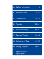
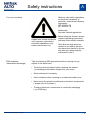
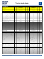
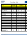
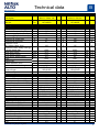
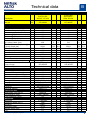
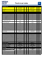
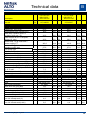
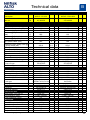
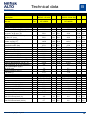
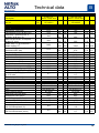
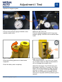
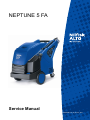
NEPTUNE 5 FA Service Manual NEPTUNE 5 FA_EN_Ver.2.0_25/11 Preface This service manual contains detailed description of the main repair work on the hot HPW NEPTUNE 5. Repair work requires a suitable testing workplace with the necessary water and power supply. If operating errors are evident, refer the customer to the operating instructions. A fault in the cleaner can have several causes as described in the section on troubleshooting. Refer to the illustrated spare parts lists during repairs. They show the assembly position and the sequence in which the individual components should be assembled. See ”Service Technical Information” (STI) sheets. They include information on technical modifications that have been made after this repair manual was printed. ”Service Technical Information” sheets are also valid as a supplement to the spare parts list until publication of a new edition. Repair manuals and ” Service Technical Information” sheets should be available at the site where repairs are carried out. It is not permitted to give them to third parties. Use original Nilfisk-ALTO spare parts only. NEPTUNE 5 FA_EN_Ver.2.0_25/11 2 A. Safety instructions 4 B. Technical data 5-18 C. Construction 19 -24 D. Function 25-31 E. Troubleshooting 32-35 F. Service / Repair 36 -48 G. Adjustment / Test 49 -53 H. Wiring diagrams Special tools / I. Spare parts 54-61 Safety instructions For your own safety A Observe valid safety regulations for electrical equipment. In particular, observe the following regulations: IEC 60335-2-79 EN 60335-2-79 Additionally: Also see national regulations Repair work should be carried out by persons instructed in electrical installations or by trained electricians only. ESD measures (electrostatic discharge) Before using the cleaner, always read the operating instructions and keep them readily available. Only allow the high pressure cleaner to be used by persons who have been trained in its use and who have been explicitly authorized to use it. Take the following ESD precautions before carrying out any repairs to the electronics: Touch the earth conductor before repairing the cleaner ( to discharge electrostatic charge from your body ). Wear wrist band if necassary. Use a conductive floor covering or a conductive table cover. Never touch the printed circuit board or electronic components ( always hold on to plastic ). Transport electronic components in conductive packaging ( e.g. ESD bag ). NEPTUNE 5 FA_EN_Ver.2.0_25/11 4 Technical data B NEPTUNE 5 FA Description Tol. Item no. Technical data Pump-Data Max. inlet pressure (bar) Max. Inlet temperature (°C) Pressure at pump head 0 Pressure @ Cylinder Head (bar) 0 Pressure @ Outlet (bar) 0 Pressure @ Gun (bar) 0 Pressure cut off @ Cylinder Head (bar) Pressure Pmax safety valve @ Cylinder Head (bar) Flow. Qiec (l/min) 2,5% Flow. Qmax (l/min) 5% Flow. Qmin, steam (l/min) 3% Type Piston type Piston diameter (mm) Stroke / Wobble disc angle Pump oil type Oil volume (l) Electrical Power supply Current consump. - hot (A) Current consump. - cold (A) Power Consumption - hot (kW) Fuse size (A) Cord type Plug type Control Contactor Electrical diagram Eletrical test data Highvoltage (HV) test (V) HV-Resistance (MΩ) Cord-resistance (Ohm) Motor-Data Motortype Rotational speed (min-1) Insulation Protection Class Nominal power [kW] Cos j NEPTUNE 5 FA_EN_Ver.2.0_25/11 5-50FA EU 400V/3 ~50Hz 16A 5-50FAX EU 400V/3 ~50Hz 16A 107146650 Test result 107146651 Test result Tol.+ Tol.- 10,0 40,0 175 180 163 140 10 10 9 8 200 250,0 13,6 14,6 6,3 NA5 Cermic 20,0 10,2 Oil BP Energol GR-XP220 0,8 Tol.+ Tol.- 10 10 9 8 10,0 40,0 180 185 166 144 10 10 9 8 10 10 9 8 5 5 205 5 5 5,0 0,3 0,7 0,2 5,0 0,3 0,7 0,2 250,0 13,6 14,6 6,3 NA5 Cermic 20,0 10,2 Oil BP Energol GR-XP220 0,8 5,0 0,3 0,7 0,2 5,0 0,3 0,7 0,2 400V/3~/50Hz 12,2 1,0 12,4 1,0 6,0 0,5 16,0 H07RN-F 4G1,5 x 6m CEE 3P+N+G / 16A PCB 24 volt 100-C16KJ10 24 106427171 3,0 3,0 0,5 400V/3~/50Hz 12,3 1,0 12,5 1,0 6,1 0,5 16,0 H07RN-F 4G1,5 x 6m CEE 3P+N+G / 16A PCB 24 volt 100-C16KJ10 24 106427171 1000 Vac ≥ 1MΩ / 500Vdc 0,2 1000 Vac ≥ 1MΩ / 500Vdc 0,2 3~ Induction 1450 Class F IP 54 5,5 0,7 3~ Induction 1450 Class F IP 54 5,5 0,7 3,0 3,0 3,0 3,0 3,0 0,5 3,0 5 Technical data B NEPTUNE 5 FA Description Item no. Technical data Heating Unit Boilerpower_input (kW) Temperature t max, @ inlet 12°C Delta temp. variance at 50 °C set point, at @ gun (°C) Boiler on time at 50 °C set point, @ inlet 12° (sec) Steam temp. t II @ outlet and v. Steam nozzle(°C) Pressure P2 @ outlet with standard nozzle (bar) Fuel pump type Oil pressure ( bar ) Nozzle size, oil CO2 content min ( % ) Efficiency burner ( % ) Soot picture Exhaust outlet temperature (°C) Exhaust temperature, cut off (°C) Fuel consump. @ dT=45 deg(kg/h) Fuel consumption (kg/h) @ 12°C inlet Water volume in coil (l) Fuel tank (l) Others Gun Lance Hose High Pressure Nozzle Noise level 1m Lpa( dBA) Noisepower LWA (dB) A Impact force Vibration ISO 5349 ( m/s² ) Protection Class Max detergent flow from full internal tank (%) Max detergent flow from full internal tank (L/min) NEPTUNE 5 FA_EN_Ver.2.0_25/11 Tol. 5-50FA EU 400V/3 ~50Hz 16A 5-50FAX EU 400V/3 ~50Hz 16A 107146650 Test result 107146651 Test result Tol.+ Tol.- 78,0 87,7 0,0 3,0 78,0 87,7 0,0 3,0 30,0 0,0 3,0 30,0 0,0 3,0 30,0 5,0 5,0 30,0 5,0 5,0 140,0 10,0 30,0 140,0 10,0 30,0 27,0 Diesel 10,0 1,75 60°H 10,5 92,0 0-1 175,0 270,0 4,0 N Tol.+ Tol.- 5,0 5,0 0,5 0,0 0,5 1,5 0,0 0,5 10,0 10,0 0,0 12,0 27,0 Diesel 10,0 1,75 60°H 10,5 92,0 0-1 175,0 270,0 4,0 6,7 4,8 17,0 6,7 4,8 ST ERGO 2000 TORNADO PLUS DN 8x10m 3/8" NT 0500 76,6 93,0 44,0 ≤ 2,5 IP X5 ST ERGO 2000 TORNADO PLUS DN 8x20m NT 0500 76,6 93,0 45,0 ≤ 2,5 IP X5 1,5 1,5 1,5 1,5 4,0 1,0 1,0 0,5 0,2 0,2 5,0 5,0 0,5 0,0 0,5 1,5 0,0 0,5 10,0 10,0 0,0 12,0 1,5 1,5 1,5 1,5 4,0 1,0 1,0 0,5 0,2 0,2 6 Technical data B NEPTUNE 5 FA Description Tol. Item no. Technical data Pump-Data Max. inlet pressure (bar) Max. Inlet temperature (°C) Pressure at pump head 0 Pressure @ Cylinder Head (bar) 0 Pressure @ Outlet (bar) 0 Pressure @ Gun (bar) 0 Pressure cut off @ Cylinder Head (bar) Pressure Pmax safety valve @ Cylinder Head (bar) Flow. Qiec (l/min) 2,5% Flow. Qmax (l/min) 5% Flow. Qmin, steam (l/min) 3% Type Piston type Piston diameter (mm) Stroke / Wobble disc angle Pump oil type Oil volume (l) Electrical Power supply Current consump. - hot (A) Current consump. - cold (A) Power Consumption - hot (kW) Fuse size (A) Cord type Plug type Control Contactor Electrical diagram Eletrical test data Highvoltage (HV) test (V) HV-Resistance (MΩ) Cord-resistance (Ohm) Motor-Data Motortype Rotational speed (min-1) Insulation Protection Class Nominal power [kW] Cos j NEPTUNE 5 FA_EN_Ver.2.0_25/11 SB FA EU 400V/3 ~50Hz 10A 107146652 Test result 5-61FA EU 400V/3 ~50 16A Tol.+ Tol.- 10,0 40,0 75 80 72 67 4 4 4 4 100 120,0 12,1 13,1 5,6 NA5 Cermic 20,0 9,2 Oil BP Energol GR-XP220 0,8 107146653 Test result Tol.+ Tol.- 4 4 4 4 10,0 40,0 190 195 193 168 10 11 11 9 10 11 11 9 5 5 215 5 5 5,0 0,3 0,7 0,2 5,0 0,3 0,7 0,2 250,0 15,8 16,9 9,2 NA5 Cermic 20,0 12,0 Oil BP Energol GR-XP220 0,8 5,0 0,4 0,8 0,3 5,0 0,4 0,8 0,3 400V/3~/50Hz 8,0 1,0 8,2 1,0 4,1 0,5 16,0 H07RN-F 4G1,5 x 6m CEE 3P+N+G / 16A PCB 24 volt 100-C12KJ10 5,5kW 106427171 + 71371 3,0 3,0 0,5 400V/3~/50Hz 15,4 1,0 16,0 1,0 7,6 0,5 16,0 H07RN-F 4G1,5 x 6m CEE 3P+N+G / 16A PCB 24 volt 100-C16KJ10 24 106427171 1000 Vac ≥ 1MΩ / 500Vdc 0,2 1000 Vac ≥ 1MΩ / 500Vdc 0,2 3~ Induction 1450 Class F IP 54 3,0 0,8 3~ Induction 1450 Class F IP 54 6,7 0,7 3,0 3,0 3,0 3,0 3,0 0,5 3,0 7 Technical data B NEPTUNE 5 FA Description SB FA EU 400V/3 ~50Hz 10A Tol. Item no. 107146652 Technical data Test result Heating Unit Boilerpower_input (kW) 67,0 Temperature t max, @ inlet 12°C 85,2 Delta temp. variance at 50 °C set point, at @ gun (°C) 30,0 Boiler on time at 50 °C set point, @ inlet 12° (sec) 30,0 Steam temp. t II @ outlet and v. Steam nozzle(°C) 140,0 Pressure P2 @ outlet with standard nozzle (bar) 27,0 Fuel pump type Diesel Oil pressure ( bar ) 12,0 Nozzle size, oil 1,35 60°H CO2 content min ( % ) 10,5 Efficiency burner ( % ) 92,0 Soot picture 0-1 Exhaust outlet temperature (°C) 160,0 Exhaust temperature, cut off (°C) 270,0 Fuel consump. @ dT=45 deg(kg/h) 3,5 Fuel consumption (kg/h) @ 12°C inlet 5,7 Water volume in coil (l) 4,8 Fuel tank (l) 17,0 Others Gun ST ERGO 2000 Lance TORNADO PLUS Hose DN 8x10m Quick 3/8" High Pressure Nozzle NT 0700 Noise level 1m Lpa( dBA) 76,4 Noisepower LWA (dB) A 92,0 Impact force N 26,0 Vibration ISO 5349 ( m/s² ) ≤ 2,5 Protection Class IP X5 Max detergent flow from full internal tank (%) 4,0 Max detergent flow from full internal tank (L/min) 0,5 NEPTUNE 5 FA_EN_Ver.2.0_25/11 5-61FA EU 400V/3 ~50 16A Tol.+ Tol.- 107146653 Test result Tol.+ Tol.- 0,0 3,0 85,0 83,0 0,0 3,0 30,0 0,0 3,0 5,0 5,0 30,0 5,0 5,0 10,0 30,0 140,0 10,0 30,0 5,0 5,0 0,5 0,0 0,5 1,5 0,0 0,5 10,0 10,0 0,0 12,0 0,0 0,1 0,0 1,5 1,5 0,0 27,0 Diesel 12,0 1,75 60°H 10,5 92,0 0-1 175,0 270,0 4,6 0,0 3,0 5,0 5,0 0,5 0,0 0,5 1,5 0,0 0,5 10,0 10,0 0,0 12,0 7,3 4,8 17,0 ST ERGO 2000 TORNADO PLUS DN 8x10m Quick 3/8" NT 0550 1,5 78,2 1,5 1,5 96,0 1,5 53,0 ≤ 2,5 IP X5 1,5 1,5 1,0 1,0 4,0 1,0 1,0 0,2 0,2 0,6 0,2 0,2 8 Technical data B NEPTUNE 5 FA Description Item no. Technical data Pump-Data Max. inlet pressure (bar) Max. Inlet temperature (°C) Pressure at pump head Pressure @ Cylinder Head (bar) Pressure @ Outlet (bar) Pressure @ Gun (bar) Pressure cut off @ Cylinder Head (bar) Pressure Pmax safety valve @ Cylinder Head (bar) Flow. Qiec (l/min) Flow. Qmax (l/min) Flow. Qmin, steam (l/min) Type Piston type Piston diameter (mm) Stroke / Wobble disc angle Pump oil type Oil volume (l) Electrical Power supply Current consump. - hot (A) Current consump. - cold (A) Power Consumption - hot (kW) Fuse size (A) Cord type Plug type Control Contactor Electrical diagram Eletrical test data Highvoltage (HV) test (V) HV-Resistance (MΩ) Cord-resistance (Ohm) Motor-Data Motortype Rotational speed (min-1) Insulation Protection Class Nominal power [kW] Cos j NEPTUNE 5 FA_EN_Ver.2.0_25/11 5-61FA NO 400V/230/3 ~ 50Hz 25/16A 5-61FAX EU 400V/3 ~50 16A Tol. 0 0 0 0 2,5% 5% 3% 107146654 Test result Tol.+ Tol.- 10,0 40,0 195 200 197 170 11 11 11 9 220 250,0 15,8 16,9 9,3 NA5 Cermic 20,0 12,0 Oil BP Energol GR-XP220 0,8 400V/3~/50Hz 15,8 16,0 7,8 16,0 H07RN-F 4G1,5 x 6m CEE 3P+N+G / 16A PCB 24 volt 100-C16KJ10 24 106427171 107146655 Test result Tol.+ Tol.- 11 11 11 9 10,0 40,0 190 195 193 168 10 11 11 9 10 11 11 9 5 5 215 5 5 5,0 0,4 0,8 0,3 5,0 0,4 0,8 0,3 250,0 15,8 16,9 9,2 NA5 Cermic 20,0 12,0 Oil BP Energol GR-XP220 0,8 5,0 0,4 0,8 0,3 5,0 0,4 0,8 0,3 1,0 1,0 0,5 3,0 3,0 0,5 3,0 3,0 1,0 1,0 0,5 400/230V/3~/50Hz 3,0 15,6 / 25 3,0 15,8 / 25 0,5 7,6 / 7,4 28 / 16 H07RN-F 4G2,5x6,0 PCB 24 volt 100-C23KJ10 106427177 1000 Vac ≥ 1MΩ / 500Vdc 0,2 1000 Vac ≥ 1MΩ / 500Vdc 0,2 3~ Induction 1450 Class F IP 54 6,7 0,7 3~ Induction 1450 Class F IP 54 6,7 0,8 3,0 3,0 9 Technical data B NEPTUNE 5 FA Description Item no. Technical data Heating Unit Boilerpower_input (kW) Temperature t max, @ inlet 12°C Delta temp. variance at 50 °C set point, at @ gun (°C) Boiler on time at 50 °C set point, @ inlet 12° (sec) Steam temp. t II @ outlet and v. Steam nozzle(°C) Pressure P2 @ outlet with standard nozzle (bar) Fuel pump type Oil pressure ( bar ) Nozzle size, oil CO2 content min ( % ) Efficiency burner ( % ) Soot picture Exhaust outlet temperature (°C) Exhaust temperature, cut off (°C) Fuel consump. @ dT=45 deg(kg/h) Fuel consumption (kg/h) Water volume in coil (l) Fuel tank (l) Others Gun Lance Hose High Pressure Nozzle Noise level 1m Lpa( dBA) Noisepower LWA (dB) A Impact force Vibration ISO 5349 ( m/s² ) Protection Class Max detergent flow from full internal tank (%) Max detergent flow from full internal tank (L/min) NEPTUNE 5 FA_EN_Ver.2.0_25/11 Tol. 5-61FAX EU 400V/3 ~50 16A 5-61FA NO 400V/230/3 ~ 50Hz 25/16A 107146654 Test result 107146655 Test result 85,0 83,0 0,0 30,0 Tol.+ Tol.- 3,0 85,0 83,0 0,0 3,0 0,0 3,0 30,0 0,0 3,0 30,0 5,0 5,0 30,0 5,0 5,0 140,0 10,0 30,0 140,0 10,0 30,0 27,0 Diesel 12,0 1,75 60°H 10,5 92,0 0-1 175,0 270,0 4,6 N Tol.+ Tol.- 5,0 5,0 0,5 0,0 0,5 1,5 0,0 0,5 10,0 10,0 0,0 12,0 27,0 Diesel 12,0 1,75 60°H 10,5 92,0 0-1 175,0 270,0 4,6 7,3 4,8 17,0 7,3 4,8 17,0 ST ERGO 2000 TORNADO PLUS DN 8x20m 3/8" NT 0550 78,2 96,0 54,0 ≤ 2,5 IP X5 ST ERGO 2000 TORNADO PLUS DN 8x20m 3/8" NT 0550 78,2 96,0 53,0 ≤ 2,5 IP X5 1,5 1,5 1,5 1,5 4,0 1,0 1,0 0,6 0,2 0,2 5,0 5,0 0,5 0,0 0,5 1,5 0,0 0,5 10,0 10,0 0,0 12,0 1,5 1,5 1,5 1,5 4,0 1,0 1,0 0,6 0,2 0,2 10 Technical data B NEPTUNE 5 FA Description Item no. Technical data Pump-Data Max. inlet pressure (bar) Max. Inlet temperature (°C) Pressure at pump head Pressure @ Cylinder Head (bar) Pressure @ Outlet (bar) Pressure @ Gun (bar) Pressure cut off @ Cylinder Head (bar) Pressure Pmax safety valve @ Cylinder Head (bar) Flow. Qiec (l/min) Flow. Qmax (l/min) Flow. Qmin, steam (l/min) Type Piston type Piston diameter (mm) Stroke / Wobble disc angle Pump oil type Oil volume (l) Electrical Power supply Current consump. - hot (A) Current consump. - cold (A) Power Consumption - hot (kW) Fuse size (A) Cord type Plug type Control Contactor Electrical diagram Eletrical test data Highvoltage (HV) test (V) HV-Resistance (MΩ) Cord-resistance (Ohm) Motor-Data Motortype Rotational speed (min-1) Insulation Protection Class Nominal power [kW] Cos j NEPTUNE 5 FA_EN_Ver.2.0_25/11 Tol. 0 0 0 0 2,5% 5% 3% 5-61FAX NO 400V/230/3 ~ 50Hz 25/16A 5-61FA Expt 440/220V/3 ~ 60Hz 23/14A 107146656 Test result 107146657 Test result Tol.+ Tol.- 10,0 40,0 195 200 197 170 11 11 11 9 220 250,0 15,8 16,9 9,3 NA5 Cermic 20,0 12,0 Oil BP Energol GR-XP220 0,8 400/230V/3~/50Hz 15,8 / 25 16 / 25 7,8 / 7,6 28 / 16 H07RN-F 4G2,5x6,0 PCB 24 volt 100-C23KJ10 106427177 Tol.+ Tol.- 11 11 11 9 10,0 40,0 190 195 193 165 10 11 11 9 10 11 11 9 5 5 215 5 5 5,0 0,4 0,8 0,3 5,0 0,4 0,8 0,3 5,0 0,4 0,8 0,3 5,0 0,4 0,8 0,3 8,9 11,3 250,0 15,8 16,9 9,2 NA5 Cermic 20,0 9,9 Oil BP Energol GR-XP220 0,8 8,9 11,3 1,0 1,0 0,5 3,0 3,0 0,5 3,0 3,0 1,0 1,0 0,5 220V/440/3~/60Hz 3,0 12,5 / 21,8 3,0 12,7 / 22 0,5 7,8 / 7 24 / 16 H07RN-F 4G2,5 x 6m PCB 24 volt 100-C23KJ10 106427177 1000 Vac ≥ 1MΩ / 500Vdc 0,2 1000 Vac ≥ 1MΩ / 500Vdc 0,2 3~ Induction 1450 Class F IP 54 6,7 0,8 3~ Induction 1450 Class F IP 54 6,7 0,8 3,0 3,0 11 Technical data B NEPTUNE 5 FA Description Item no. Technical data Heating Unit Boilerpower_input (kW) Temperature t max, @ inlet 12°C Delta temp. variance at 50 °C set point, at @ gun (°C) Boiler on time at 50 °C set point, @ inlet 12° (sec) Steam temp. t II @ outlet and v. Steam nozzle(°C) Pressure P2 @ outlet with standard nozzle (bar) Fuel pump type Oil pressure ( bar ) Nozzle size, oil CO2 content min ( % ) Efficiency burner ( % ) Soot picture Exhaust outlet temperature (°C) Exhaust temperature, cut off (°C) Fuel consump. @ dT=45 deg(kg/h) Fuel consumption (kg/h) @ 12°C inlet Water volume in coil (l) Fuel tank (l) Others Gun Lance Hose High Pressure Nozzle Noise level 1m Lpa( dBA) Noisepower LWA (dB) A Impact force Vibration ISO 5349 ( m/s² ) Protection Class Max detergent flow from full internal tank (%) Max detergent flow from full internal tank (L/min) NEPTUNE 5 FA_EN_Ver.2.0_25/11 Tol. 5-61FAX NO 400V/230/3 ~ 50Hz 25/16A 5-61FA Expt 440/220V/3 ~ 60Hz 23/14A 107146656 Test result 107146657 Test result 85,0 83,0 0,0 30,0 Tol.+ Tol.- 3,0 85,0 83,0 0,0 3,0 0,0 3,0 30,0 0,0 3,0 30,0 5,0 5,0 30,0 5,0 5,0 140,0 10,0 30,0 140,0 10,0 30,0 27,0 Diesel 12,0 1,75 60°H 10,5 92,0 0-1 175,0 270,0 4,6 N Tol.+ Tol.- 5,0 5,0 0,5 0,0 0,5 1,5 0,0 0,5 10,0 10,0 0,0 12,0 27,0 Diesel 12,0 1,75 60°H 10,5 92,0 0-1 175,0 270,0 4,6 7,3 4,8 17,0 7,3 4,8 17,0 ST ERGO 2000 TORNADO PLUS DN 8x20m 3/8" NT 0550 78,2 96,0 54,0 ≤ 2,5 IP X5 ST ERGO 2000 TORNADO PLUS DN 8x20m 3/8" NT 0550 78,2 96,0 53,0 ≤ 2,5 IP X5 1,5 1,5 1,5 1,5 4,0 1,0 1,0 0,6 0,2 0,2 5,0 5,0 0,5 0,0 0,5 1,5 0,0 0,5 10,0 10,0 0,0 12,0 1,5 1,5 1,5 1,5 4,0 1,0 1,0 0,6 0,2 0,2 12 Technical data B NEPTUNE 5 FA Description Item no. Technical data Pump-Data Max. inlet pressure (bar) Max. Inlet temperature (°C) Pressure at pump head Pressure @ Cylinder Head (bar) Pressure @ Outlet (bar) Pressure @ Gun (bar) Pressure cut off @ Cylinder Head (bar) Pressure Pmax safety valve @ Cylinder Head (bar) Flow. Qiec (l/min) Flow. Qmax (l/min) Flow. Qmin, steam (l/min) Type Piston type Piston diameter (mm) Stroke / Wobble disc angle Pump oil type Oil volume (l) Electrical Power supply Current consump. - hot (A) Current consump. - cold (A) Power Consumption - hot (kW) Fuse size (A) Cord type Plug type Control Contactor Electrical diagram Eletrical test data Highvoltage (HV) test (V) HV-Resistance (MΩ) Cord-resistance (Ohm) Motor-Data Motortype Rotational speed (min-1) Insulation Protection Class Nominal power [kW] Cos j NEPTUNE 5 FA_EN_Ver.2.0_25/11 Tol. 5-61FAX AU 400V/3 ~50 16A 5-44FA JP 200V/3 ~50Hz 20A 107146658 Test result 107146660 Test result Tol.+ Tol.- 0 10,0 40,0 195 11 0 0 0 200 197 170 2,5% 5% 3% Tol.+ Tol.- 11 10,0 40,0 157 9 9 11 11 9 11 11 9 162 149 130 9 8 7 9 8 7 220 5 5 182 5 5 250,0 16,3 16,7 9,3 NA5 Cermic 20,0 12,0 Oil BP Energol GR-XP220 0,8 5,0 0,4 0,8 0,3 5,0 0,4 0,8 0,3 250,0 13,5 14,5 5,8 NA5 Cermic 20,0 10,2 Oil BP Energol GR-XP220 0,8 5,0 0,3 0,7 0,2 5,0 0,3 0,7 0,2 1,0 1,0 0,5 3,0 3,0 0,5 3,0 3,0 400V/3~/50Hz 15,4 16,0 7,6 16,0 8,9 11,3 H07RN-F 4G1,5 x 6m PCB 24 volt 100-C23KJ10 106427171 200V/3~/50Hz 18,7 18,9 5,4 20,0 Power cord VCT 4x3,5x6m PCB 24 volt 100-C30 24V/50-60H 106421534 1000 Vac ≥ 1MΩ / 500Vdc 0,2 1000 Vac ≥ 1MΩ / 500Vdc 0,2 3~ Induction 1450 Class F IP 54 6,7 0,7 3~ Induction 1450 Class F IP 54 4,0 0,8 1,0 1,0 0,5 3,0 3,0 3,0 0,5 3,0 13 Technical data B NEPTUNE 5 FA 5-61FAX AU 400V/3 ~50 16A Description Item no. Technical data Heating Unit Boilerpower_input (kW) Temperature t max, @ inlet 12°C Delta temp. variance at 50 °C set point, at @ gun (°C) Boiler on time at 50 °C set point, @ inlet 12° (sec) Steam temp. t II @ outlet and v. Steam nozzle(°C) Pressure P2 @ outlet with standard nozzle (bar) Fuel pump type Oil pressure ( bar ) Nozzle size, oil CO2 content min ( % ) Efficiency burner ( % ) Soot picture Exhaust outlet temperature (°C) Exhaust temperature, cut off (°C) Fuel consump. @ dT=45 deg(kg/h) Fuel consumption (kg/h) @ 12°C inlet Water volume in coil (l) Fuel tank (l) Others Gun Lance Hose High Pressure Nozzle Noise level 1m Lpa( dBA) Noisepower LWA (dB) A Impact force Vibration ISO 5349 ( m/s² ) Protection Class Max detergent flow from full internal tank (%) Max detergent flow from full internal tank (L/min) NEPTUNE 5 FA_EN_Ver.2.0_25/11 Tol. 107146658 Test result Tol.+ Tol.- 85,0 80,8 0,0 30,0 107146660 Test result Tol.+ Tol.- 3,0 67,0 77,5 0,0 3,0 0,0 3,0 30,0 0,0 3,0 30,0 5,0 5,0 30,0 5,0 5,0 140,0 10,0 30,0 140,0 10,0 30,0 27,0 Diesel 12,0 1,75 60°H 10,5 92,0 0-1 175,0 270,0 4,8 N 5-44FA JP 200V/3 ~50Hz 20A 5,0 5,0 0,5 0,0 0,5 1,5 0,0 0,5 10,0 10,0 0,0 12,0 27,0 Diesel 12,0 1,35 60°H 10,5 92,0 0-1 160,0 270,0 3,9 7,3 4,8 17,0 5,7 4,8 17,0 ST ERGO 2000 TORNADO PLUS DN 8x20m 3/8" DN 8x20m 3/8" 78,2 96,0 56,0 ≤ 2,5 IP X5 ST ERGO 2000 TORNADO PLUS DN 8x20m 3/8" NT 0500 76,4 92,0 42,0 ≤ 2,5 IP X5 1,5 1,5 1,5 1,5 4,0 1,0 1,0 0,7 0,2 0,2 5,0 5,0 0,5 0,0 0,5 1,5 0,0 0,5 10,0 10,0 0,0 12,0 1,5 1,5 1,5 1,5 4,0 1,0 1,0 0,5 0,2 0,2 14 Technical data B NEPTUNE 5 FA 5-44FA JP 200/3 ~60Hz 20A Description Item no. Technical data Pump-Data Max. inlet pressure (bar) Max. Inlet temperature (°C) Pressure at pump head Pressure @ Cylinder Head (bar) Pressure @ Outlet (bar) Pressure @ Gun (bar) 107146661 Test result 0 0 0 0 Pressure cut off Pressure Pmax safety valve @ Flow. Qiec (l/min) 2,5% Flow. Qmax (l/min) 5% Flow. Qmin, steam (l/min) 3% Type Piston type Piston diameter (mm) Stroke / Wobble disc angle Pump oil type Oil volume (l) Electrical Power supply Current consump. - hot (A) Current consump. - cold (A) Power Consumption - hot (kW) Fuse size (A) Cord type Plug type Control Contactor Electrical diagram Eletrical test data Highvoltage (HV) test (V) HV-Resistance (MΩ) Cord-resistance (Ohm) Motor-Data Motortype Rotational speed (min-1) Insulation Protection Class Nominal power [kW] Cos j NEPTUNE 5 FA_EN_Ver.2.0_25/11 10,0 40,0 157 162 149 130 182 250,0 13,4 14,4 5,8 NA5 Cermic 20,0 8,4 5-50FAX USA 230V/1 ~60Hz 30A Tol.+ Tol.- 107146665 Test result Tol.+ Tol.- 9 9 10,0 40,0 133 9 8 7 9 8 7 138 118 111 8 7 6 8 7 6 5 5 158 5 5 5,0 0,3 0,7 0,2 5,0 0,3 0,7 0,2 250,0 16,6 16,9 9,3 NA5 Cermic 20,0 10,2 5,0 0,4 0,8 0,3 5,0 0,4 0,8 0,3 Oil BP Energol 7 7 0,8 Oil BP Energol 0,8 200V/3~/60Hz 16,6 17,5 5,1 20,0 Power cord VCT 4x3,5x6m PCB 24 volt 100-C30 24V/50-60H 106421534 230V/1~/60Hz 3,0 28,0 1,0 3,0 26,8 1,0 0,5 8,0 0,5 30,0 SJOW AWG10/3X9.0 NEMA 6-30P PCB 24 volt 100-C12KJ10 5,5kW 106420540 1,0 1,0 0,5 1000 Vac ≥ 1MΩ / 500Vdc 0,2 1000 Vac ≥ 1MΩ / 500Vdc 0,2 3~ Induction 1450 Class F IP 54 4,0 0,8 1~ Induction 1450 Class F IP 54 5,2 0,8 3,0 3,0 3,0 3,0 3,0 0,5 3,0 15 Technical data B NEPTUNE 5 FA 5-44FA JP 200/3 ~60Hz 20A Description Item no. Technical data Heating Unit Boilerpower_input (kW) Temperature t max, @ inlet 12°C Delta temp. variance at 50 °C set point, at @ gun (°C) Boiler on time at 50 °C set point, @ inlet 12° (sec) Steam temp. t II @ outlet and v. Steam nozzle(°C) Pressure P2 @ outlet with standard nozzle (bar) Fuel pump type Oil pressure ( bar ) Nozzle size, oil CO2 content min ( % ) Efficiency burner ( % ) Soot picture Exhaust outlet temperature (°C) Exhaust temperature, cut off (°C) Fuel consump. @ dT=45 deg(kg/h) Fuel consumption (kg/h) @ 12°C inlet Water volume in coil (l) Fuel tank (l) Others Gun Lance Hose High Pressure Nozzle Noise level 1m Lpa( dBA) Noisepower LWA (dB) A Impact force Vibration ISO 5349 ( m/s² ) Protection Class Max detergent flow from full internal tank (%) Max detergent flow from full internal tank (L/min) NEPTUNE 5 FA_EN_Ver.2.0_25/11 Tol. 107146661 Test result 67,0 78,2 30,0 30,0 140,0 27,0 Diesel 12,0 1,35 60°H 10,5 92,0 0-1 160,0 270,0 3,9 5-50FAX USA 230V/1 ~60Hz 30A Tol.+ Tol.- 3,0 78,0 74,4 0,0 3,0 0,0 3,0 30,0 0,0 3,0 5,0 5,0 30,0 5,0 5,0 10,0 30,0 140,0 10,0 30,0 5,0 5,0 0,5 0,0 0,5 1,5 0,0 0,5 10,0 10,0 0,0 12,0 27,0 Diesel 10,0 1,75 60°H 10,5 92,5 0-1 175,0 270,0 4,8 4,8 17,0 6,7 4,8 17,0 ST ERGO 2000 TORNADO PLUS DN 8x20m 3/8" NT 0500 76,4 92,0 41,0 ≤ 2,5 IP X5 ST ERGO 2000 TORNADO PLUS DN 8x20m 3/8" NT 0750 80,0 94,0 47,0 ≤ 2,5 IP X5 4,0 0,5 Tol.+ Tol.- 0,0 5,7 N 107146665 Test result 1,5 1,5 1,5 1,5 1,0 1,0 0,2 0,2 5,0 5,0 0,5 0,0 0,5 1,5 0,0 0,5 10,0 10,0 0,0 12,0 1,5 1,5 1,5 1,5 4,0 1,0 1,0 0,7 0,2 0,2 16 Technical data B NEPTUNE 5 FA Description Tol. Item no. Technical data Pump-Data Max. inlet pressure (bar) Max. Inlet temperature (°C) Pressure at pump head 0 Pressure @ Cylinder Head (bar) 0 Pressure @ Outlet (bar) 0 Pressure @ Gun (bar) 0 Pressure cut off @ Cylinder Head (bar) Pressure Pmax safety valve @ Cylinder Head (bar) Flow. Qiec (l/min) 2,5% Flow. Qmax (l/min) 5% Flow. Qmin, steam (l/min) 3% Type Piston type Piston diameter (mm) Stroke / Wobble disc angle Pump oil type Oil volume (l) Electrical Power supply Current consump. - hot (A) Current consump. - cold (A) Power Consumption - hot (kW) Fuse size (A) Cord type Plug type Control Contactor Electrical diagram Eletrical test data Highvoltage (HV) test (V) HV-Resistance (MΩ) Cord-resistance (Ohm) Motor-Data Motortype Rotational speed (min-1) Insulation Protection Class Nominal power [kW] Cos j NEPTUNE 5 FA_EN_Ver.2.0_25/11 5-61FA EU 400V/3 ~50 16A 5-61FAX EU 400V/3 ~50 16A 107146670 Test result 107146671 Test result Tol.+ Tol.- 10,0 40,0 190 195 193 168 10 11 11 9 215 250,0 15,8 16,9 9,2 NA5 Cermic 20,0 12,0 Oil BP Energol GR-XP220 0,8 Tol.+ Tol.- 10 11 11 9 10,0 40,0 195 200 197 170 11 11 11 9 11 11 11 9 5 5 220 5 5 5,0 0,4 0,8 0,3 5,0 0,4 0,8 0,3 250,0 15,8 16,9 9,3 NA5 Cermic 20,0 12,0 Oil BP Energol GR-XP220 0,8 5,0 0,4 0,8 0,3 5,0 0,4 0,8 0,3 400V/3~/50Hz 1,0 15,4 1,0 16,0 7,6 0,5 16,0 H07RN-F 4G1,5 x 6m CEE 3P+N+G / 16A PCB 24 volt 100-C16KJ10 24 106427171 3,0 3,0 0,5 400V/3~/50Hz 15,8 1,0 16,0 1,0 7,8 0,5 16,0 H07RN-F 4G1,5 x 6m CEE 3P+N+G / 16A PCB 24 volt 100-C16KJ10 24 106427171 1000 Vac ≥ 1MΩ / 500Vdc 0,2 1000 Vac ≥ 1MΩ / 500Vdc 0,2 3~ Induction 1450 Class F IP 54 6,7 0,7 3~ Induction 1450 Class F IP 54 6,7 0,7 3,0 3,0 3,0 3,0 3,0 0,5 3,0 17 Technical data B NEPTUNE 5 FA Description Item no. Technical data Heating Unit Boilerpower_input (kW) Temperature t max, @ inlet 12°C Delta temp. variance at 50 °C set point, at @ gun (°C) Boiler on time at 50 °C set point, @ inlet 12° (sec) Steam temp. t II @ outlet and v. Steam nozzle(°C) Pressure P2 @ outlet with standard nozzle (bar) Fuel pump type Oil pressure ( bar ) Nozzle size, oil CO2 content min ( % ) Efficiency burner ( % ) Soot picture Exhaust outlet temperature (°C) Exhaust temperature, cut off (°C) Fuel consump. @ dT=45 deg(kg/h) Fuel consumption (kg/h) @ 12°C inlet Water volume in coil (l) Fuel tank (l) Others Gun Lance Hose High Pressure Nozzle Noise level 1m Lpa( dBA) Noisepower LWA (dB) A Impact force Vibration ISO 5349 ( m/s² ) Protection Class Max detergent flow from full internal tank (%) Max detergent flow from full internal tank (L/min) NEPTUNE 5 FA_EN_Ver.2.0_25/11 Tol. 5-61FA EU 400V/3 ~50 16A 5-61FAX EU 400V/3 ~50 16A 107146670 Test result 107146671 Test result Tol.+ Tol.- 85,0 83,0 0,0 3,0 85,0 83,0 0,0 3,0 30,0 0,0 3,0 30,0 0,0 3,0 30,0 5,0 5,0 30,0 5,0 5,0 140,0 10,0 30,0 140,0 10,0 30,0 27,0 Diesel 12,0 1,75 60°H 10,5 92,0 0-1 175,0 270,0 4,6 7,3 4,8 17,0 5,0 5,0 0,5 0,0 0,5 1,5 0,0 0,5 10,0 10,0 0,0 12,0 0,0 0,1 0,0 0,0 ST ERGO 2000 TORNADO PLUS DN 10x10m Quick 3/8" N Tol.+ Tol.- 27,0 Diesel 12,0 1,75 60°H 10,5 92,0 0-1 175,0 270,0 4,6 7,3 4,8 17,0 5,0 5,0 0,5 0,0 0,5 1,5 0,0 0,5 10,0 10,0 0,0 12,0 0,0 0,1 0,0 0,0 ST ERGO 2000 TORNADO PLUS DN 10x20m 3/8" 78,2 96,0 53,0 ≤ 2,5 IP X5 1,5 1,5 1,5 1,5 78,2 96,0 54,0 ≤ 2,5 IP X5 1,5 1,5 1,5 1,5 4,0 1,0 1,0 4,0 1,0 1,0 0,6 0,2 0,2 0,6 0,2 0,2 18 Construction C Neptune 5 FA Variants. Single phase: 5-50 US. Three phase: 5-44 JP, 5-50 EU, 5-61 EU, 5-61NO, 5-61 EXP, 5-61 AU, 5-FA SB. X vs. Standard : Hose Reel and Hose lenght 15m on X models. _ : These numbers refer to the theoretical total impact of spraying water calculated by the formula: Impact = Q1 x √ P1 x 0.24 [ N ] P1 = bar. Q1 = l/min.v P1. The Neptune 5 FA is build with a NA5 pump. The by-pass system is flow activated, unlike the pressure activated by-pass system known from previous Neptune machines. The frame, cabinet, detergent tank and fuel tank is identical to previous Neptune 5 models. Burner fan housing Boiler Anti scale pump Fuel pump Water break tank Flow control Anti scale tank Pressure/water regulation Safety valve By-pass valve Fig.C.1: Side view Fuel filter Fuel gauge Boiler inlet Electrodes Flame sensor Ignition transformer Fuel nozzle Boiler outlet—with temperature sensor Exhaust thermal safety sensor Fig.C.2: Top view NEPTUNE 5 FA_EN_Ver.2.0_25/11 19 Construction 4 C 5 6 2 3 7 1 8 9 Fig.C.3: NEPTUNE 5 FA 12 11 10 Fig.C.3: Frame & cabinet parts 1. Lance holder 7. Handle 2. Detergent tank 8. Detergent tank 3. Fuel tank 9. Water break tank 4. Fuel filter 10. External detergent filter 5. Top cover 11. Frame 6. Side cabinet—right 12. Side cabinet—left NEPTUNE 5 FA_EN_Ver.2.0_25/11 20 Construction C The electric box (Fig.C.6) contains the control board, the transformer. relays, fuses,and connection terminals. The cover plate is mounted with the main switch, the display, the temperature adjustment and five status/warningLights (Fig.C.4). The cover is sealed around the edge and around the manometer and the detergent valve. Main switch S1: OFF- COLD - HOT Adjustment: Temperature settings Service interval settings Display: Temperature setting Error mesage Running hours Sevice interval setting Operation Fig.C.4: Operation panel Main switch S1 Display board A2 Pressure Gauge Fuel Detergent: A/B Service Anti stone Fig.C.5: Panel - inside Control board A1 Ignition transformer T1 Fuse F11 Contactor K1 NEPTUNE 5 FA_EN_Ver.2.0_25/11 Fig.C.6: Electrical box 21 Construction C The electric control system is built up around the control board A1 which is divided into two systems, a 5V DC system on one side to supply the sensors B8, B4, B6, B1,B9, B7 and on the other side it supplies the actors (contactor, relay, solenoid valve, anti stone pump) with 24V AC. The transformer T1 supplies the system with 24V and 8V AC. X7 is the connector to a remote control which is available as an accessory. X2 is the connector to the Nilfisk-Alto Datalogger and to service interval settings. Detailed function is described in chapter D. Detailed adjustment is described in chapter G. Electrical diagrams can be found in chapter H. 1: Switch for change of temperature display Celsius/fahrenheit. X9: Hour display setting X10: By-pass time canceling 2: Switch for by-pass setting when connecting a remote control. X7: Remote control X2: Data logger B 7 S 1 B 9 Y2 B 1 K2 B 6 K1 B 4 Fig.C.7: PCB A1 Y1 NEPTUNE 5 FA_EN_Ver.2.0_25/11 B2 MT B3 24V 8V Fuse F1 Fuse F2 22 Construction C The boiler is the heat generating part of a hot water machine. It consists of a labyrinth-constructed tube coil, which encloses the combustion chamber. The tube coil is enclosed by a double container with boiler jacket, bottom, and top in a sandwich construction, between which the combustion air is routed into the combustion. An insulating material placed in the bottom of the boiler makes sure that the inner bottom, among other things, is protected from super heating. Flame sensor Electrodes Fuel nozzle Exhaust Water outlet Water inlet Top plate Air distributor Flame tube top part Burner tube Flame tube Air inlet Fixation spacer Outer jacket Inner jacket Mounting plate Fig.C.8: Boiler Insolation NEPTUNE 5 FA_EN_Ver.2.0_25/11 23 Construction C Fig.C.9: Motor - Pump unit The NA 5 three piston axial pump used in Neptune 5 FA is build in line with the electrical motor as one compact unit. Fig.C.10: By-pass valve The start/stop system in Neptune 5 FA is flow Activated. NEPTUNE 5 FA_EN_Ver.2.0_25/11 Fig.C.11: Flow control The flow control checks if there is flow in the system, to stop and start the machine. 24 Function D If the machine and the power supply are working correctly the following will happend during start up. Display Suction from pump Pressure Start—hot Start—cold B A Detergent A/B Temperature setting Status indicators Detergent valve A-B Connected to water tank Fig.D.1: Display Depending on the electronic set-up the following will happen. When the start switch is turned into cold water mode the display will show the running hours the machine has been used in cold and hot mode (but it doesn’t count ‘standby time’). 7 second later the motor will start building up pressure to cut off pressure and then by-pass. 20 second later the motor stops, the display shows the set point of the temperature in degC or degF. The indicator lights up the green light on the plug icon only. The manometer shows by-pass pressure. Now the machine is on stand-by in cold water mode. By switching to hot water mode the machine is then in stand-by in hot water mode. When the spray handle is activated, flow will activate the flow switch and start the motor pump unit. At the same time anti scale pump starts up and the fan for the burner starts ventilating the combustion chamber for 3 sec. before the fuel is pumped into the boiler and the combustion takes place. The temperature will now raise until the setpoint, has been reached. The combustion will stop, but the water temperature will climb a little higher before it gets down to the setpoint. In the meantime the fan and the ignition are still working. When the combustion starts at the setpoint, the temperature will go a little lower before it starts rising. The detergent valve makes it possible to choose between detergent A from the built in tank or detergent B from the canister. With the valve in off position as shown, it draws in water from the tank to clean the channels. NEPTUNE 5 FA_EN_Ver.2.0_25/11 25 Function D When the machine is running in hot water mode, the fan draws in air and leads it into the side of the boiler, around and between the two jackets up to the air distributor. In this way the air is preheated before it is mixed with the oil spray from the nozzle. The cold water enters the boiler at the inner circle where the temperature is highest. By doing so, it will minimize the condensation of water on the surface of the tube. Fig.D.2: Hot water function The fuel is drawn from the tank through the fuel filter to the pump, while in hot water mode it passes through the magnetic solenoid valve to the nozzle in the air distributor if combustion is required. Fuel is returned to the tank if combustion is not required. The ignition transformer is active in hot water mode and it will form sparks between the electrodes. If the flame is not developed, a flame sensor placed on top of the boiler will secure that fuel pump is automatically stopped, and a fault code will be displayed on the panel. When the machine is running normally, and the boiler is burning normally, the flame is pressed against the insulated bottom. The temperature is here approximately. 1100°C. The hot exhaust gas is pressed further round the labyrinth-shaped combustion chamber, where the heat is absorbed by the water flow in the tubes. NEPTUNE 5 FA_EN_Ver.2.0_25/11 26 Function D Fig.D.3: Sensors & actors Sensors: B1: Temperature sensor in the outlet from the boiler. Controls the combustion (Y1 on/off) according to setting. B2: Flow switch sense the flow out of the pump into the boiler and controls solenoid Y1 on/off. B3: Safety thermal switch placed in the exhaust of the machine, if temperature > 270 deg C 222 deg F will switch off, if the burner keeps burning without water flow through the boiler. B4: Flow switch controls the motor start/stop. When pressure is higher than working pressure the switch will open and the motor stops. B6: Oil level-sensor stops the machine if the pump is low on oil. Activates red light on panel. B7: Flame-sensor detects light from the flame. If the flame is not detected when it should be there, the machine will be stopped. B8: Level switch Anti-Stone liquid. If low, yellow light will light up. B9: Level switch fuel (stops the fuel valve) when low on fuel and yellow light appears on the panel. MT: Temperature switch stops the motor if the temperature in the windings is >160 deg C (320 deg F). Automatic reset. Actors: Y1 Solenoid opens/closes the fuel for the burner. T2: Ignition transformer is on when burner fan is running. The machine is supplied with main power which is transformed into 8V AC to supply the microprocessor and sensors and 24VAC to supply the actors (contactor, relay, solenoid valve). To run the machine on hot water the following must be ok: on the front panel S1 and the temperature setting on hot and the spray handle open. If all the sensors are closed and ok K1 will start the motor and K2 the ignition and fan. Y1 will open and let in oil to the combustion chamber. If the flow stops B2 will open and the 24V supply to the solenoid Y1 will be interrupted and the combustion will stop. NEPTUNE 5 FA_EN_Ver.2.0_25/11 27 Function C A D D H B E G F J I Fig.D.4: Motor/pump A: Stator. E: Suction valve. B: Rotor. F: Pressure valve. C: Wobble disc. G: BY-pass housing D: Ceramic piston. H: Water regulation valve The three ceramic pistons ”D” are driven by a wobble disc ”C”, the mission of which is to transform the rotating power from the rotor ”B” into the reciprocating pumping pistons ”D”. The angle of the wobble disc ”C” decides the volume of water which is sucked through the suction valves ”E” and pressed out through the pressure valves ”F”. The inlet ”I” and the outlet ”J” are connected directly to the By-pass valve ”G”. The water volume can be adjusted by the regulation valve ”H”. NEPTUNE 5 FA_EN_Ver.2.0_25/11 28 Function D G F H E D I J K C B A Fig.D.5: Working pressure Machine is started and the gun ”J” with correct lance/nozzle is open Machine runs in working pressure ”K”: The water is pressed from the pump outlet ”A” into the by-pass housing ”C”. The water runs through the bottom of by-pass housing ”C” and directely to the outlet ”I”. Due to the water pressure the by-pass piston ”B” is pressed up and the seat ”E” is closed. G F E D H I J K C B A Fig.D.6: By-pass pressure Machine is started and the gun is closed - By-pass pressure: When the gun ”J” closes, the pressure inside the by-pass housing equalizes and the by-pass piston ”B” is pressed down by the tension of it’s spring. The seat ”E” in the top of by-pass piston opens. The water runs from the pump outlet ”A” into the by-pass housing ”C”. Due to the closed gun ”J” and the opening in the by-pass seat ”E”, the water runs back into the suction side of the pump through the valve ”D”. NEPTUNE 5 FA_EN_Ver.2.0_25/11 29 Function D C B A Fig.D.7: By-pass pressure The by-pass pressure is determined of the spring tension in valve ”A”. The tension is fixed and will bring out a by-pass pressure in about 30 - 35 bar. Valve ”A” also secures the self suction ability. The cut off pressure when the gun is released, is determined of the adjustment screw ”B”. When the screw is tightened the cut off pressure will rice and by loosening it the pressure will drop. The safety valve ”C” has no function under normal circumstances. The pressure of the safety valve is set to about 25 - 30 bar above the cut off pressure. The safety valve will open if the by-pass valve is stocked and lead water to the suction side of the pump. G F E D H I K C B A Fig.D.8: Water reduction When the water regulation ”G” is turned counter clock wise, the seat ”H” opens and the water runs both to the outlet of the by-pass housing and in by-pass to the suction side of the pump. The pressure ”K” will drop depending of the size of the opening in seat ”H”. NEPTUNE 5 FA_EN_Ver.2.0_25/11 30 Function D G E I J F D A: Hose connection/valve seat. B: Non return valves. C: Inlet for water from water supply. D: Magnet piston for reed switch E E: Reed switch for start of motor/pump. F: Water inlet from pump. G: Non return valve/magnet piston for H H: Reed switch for start of heating system. I: Water outlet. J: Back flow restriction. H A B C Fig.D.9: Flow control Water supply connected to the machine: Water from supply passes the non-return valves ”B” and lift up the piston ”D”. Machine started in cold/hot water mode: When piston ”D” is lifted up by the flow, the magnet in piston ”D” closes the reed contact NO ”E” which gives a signal to the PC board, which starts up the motor/pump unit. The flow from the pump lifts up piston ”G”. To secure the flow is all right, the magnet in piston ”G” closes the reed contact NC ”H” which gives the signal to the PC board. In hot water mode this signal controls the fuel solenoid valve and the anti scale pump. The fuel solenoid valve and the anti scale pump will activate when the PC board receives the signal from reed contact ”H”. Piston ”G”: When the gun is closed, piston ”G” closes the inlet of the flow control. Inside the piston there is a retaining valve which opens when the outlet pressure in the flow control is more than10 bar higher than the inlet pressure, when the gun is released. This pressure differens will improve the movement of piston ”G” when the gun again is activated. NEPTUNE 5 FA_EN_Ver.2.0_25/11 31 Troubleshooting E When trouble-shooting it will be a great help if you can locate the fault as being either an external fault or an internal fault. External faults are due to either improper maintenance, incorrect operation or operation under particularly straining conditions. External faults usually represent the following: The below-mentioned conditions have been checked and found ok: Check point 1. Installation fuse blown. Yes No Comment 3. Cable bursting. 4. Too long, to small or defective extension cables. 5. High/low pressure nozzle blocked or worn. 6. Spray handle defective or leaky. 7. High pressure hose too long or defective. 8. Water inlet filter blocked (dirty water). 9. Inadequate supply of mains water. 10. Air sucked into the pump (detergent tank empty). 11. Detergent system blocked (dried-up). 12. Inlet water too hot. 13. Fuel filter blocked. 14. Air adjustment faulty. 15. Fuel level low. Water in tank. 2. Plug defective. The internal faults require a systematic going through of the motor pump by a Nilfisk-ALTO technician. In order to establish the reason of the fault with certainty, it may be a help to use the over-leaf yes/no diagrams. NEPTUNE 5 FA_EN_Ver.2.0_25/11 32 Troubleshooting E Below there is a list of the actual detectable errors with the belonging code. The codes „SEO“, „SEC“, „LHE“ and „FLF“ only occure in Hotwater operation. Error describtion Code Display Error micro-processor ( uProcessor ) UPC ( Sensor closed ) SEC ( Sensor open ) SEO ( Flow failure ) FLF ( Flow problem or less water) FLO ( Leakage ) LEA ( Hot safety temp-switch) HOS ( Pump oil error ) POL ( Light, fuel not activated) LHL ( No light, fuel enabled ) LHE ( Fuel empty ) FUE Thermal protector motor open ( Hot motor protector ) HOP Temp-sensor closed (Short circuit) Temp-sensor open Flow sensor for start open / flow-sensor for hot water closed Flow sensor open while motor is running Leakage (detect. by micro-sw. / flow-sens.) Safety temperature switch open Pumpoil-switch open ( LED indication ) Light indication burner with fuel disabled No light indication burner with fuel enabled Fuel-level switch open ( LED indication ) NEPTUNE 5 FA_EN_Ver.2.0_25/11 33 Troubleshooting E ERROR CODE CHECK LIST Display Symptom HOS Hot Safety temperature switch B3 opens when temp is higher than 270 deg C (518 deg F). POL Pump Oil Low Switch B6 open. Outer cause Inner cause Flow and pressure switch out of adWire defective. justment. Oil residue in boiler. Boiler clogged up. Check Boiler security adjustment. Switch B3 must be changed IF open. Wire defective. Oil seals worn out. B6 Switch. LHL Light sensor B7 see Light, when Y1 is not activated Sensor not in Flame sensor short circuit place. (Cold water operation, not Wire defective. possible). Oil residue in boiler is burning. Y1 Leaky. Egnition failure. Oil pressure. Nozzle Electrode Flame sensor. HOP Pump pressure Fan on motor detoo high. Hot Motor Protector Motor winding >160degC Temp in room fective. Fuse(F1 2amp). >40degC (320degF). (104degF). Sensor in windings. FLF Flow Failure Flow switch B2 closed and Wire defective B4 open. Reed switch. LHE No Light, Fuel Enabled. Light sensor B7 see no light when Y1 is open. FUE LEA Fuel Empty. Levelswitch B9 Open. Leakage. Three times start without flow. Wire defective. Spark failure. Flow switch off. Oil filter blocked soot on glass. Fuse (F11). Sensor B7. Wire defective. B9 switch Leaky system. U-processor failure. SEO Temperature Sensor Wire defective. Open. Temperature Sensor CloWire defective. sed. Air in suction Flow switch B2open and water. flow switch B4 close. No water. FLO NEPTUNE 5 FA_EN_Ver.2.0_25/11 Leaky non-return valve. B4 switch. Water in electric system. UPC SEC Flow piston hanging. B1 switch B1 switch Detergent valve. 34 Troubleshooting E Boiler performance: The symptom is reduced performance of the pump effect or the boiler effect. The symptom of reduced boiler effect is a lower water outlet temperature than the set value. The possible causes for this are as follows: Scale deposits in boiler tube: Scale formation acts as insulation and reduces heat transfer to the water. The result is raised flue gastemperature = increased flue gas loss. Cause: The hardness of the water Remedy: Descale boiler tube. Sooted boiler tube: Soot has the same effect as scale deposits, i.e. that they are both insulating against the heat transfer to the water and results in increased flue gas temperature = increased flue gas loss. Other symptoms are that the machine smokes during steady operation. Cause 1: Air deficiency. Remedy: Check air adjustment and fan attachment to boiler. Cause 2: Bad oil/air mixture. Remedy: Check oil pressure and oil quality. Replace the oil nozzle. Adjust air diffuser. Cause 3: Unfinished combustion. Remedy: Check bottom insulation, boiler top gasket between tube and inner boiler jacket in top cover. Check burner tube. Cause 4: Unstable ignition. Remedy: Check electrodes. Adjust the air quantity (less air). Cause 5: Leaky solenoid valve on pump Y1. Remedy: Check/replace solenoid valve Y1. Low oil pressure Cause 1: Incorrect adjustment. Remedy: Adjust pump pressure (12 bar, see page 45). Cause 2: Filter blocked, defective pump. Remedy: Replace filter/pump. Empty and clean tank. Full water quantity at steam stage Cause: Mechanical defect of by-pass valve or adjustment. Remedy: Check by-pass valve. NEPTUNE 5 FA_EN_Ver.2.0_25/11 35 Service / Repair F Observitions Fig.F.01: Data Plate Fig.F.02: Water filter—Cleaning Prior to any maintenance, identify the External. Back left-hand side Internal. Inside the Electrical Box. As required clean the water filter. Unscrew connector for water break tank. Pull out the filter by use of a nose pliers. Clean the filter and inspect for damages. Clean the filter. Replace if necessary. Oil Maintenance Fuel filter. Fig.F.03: Oil extention. Fig.F.04: Fuel filter. Check the pump oil quality and quantity. Check the fuel filter and replace if necessary. machine version at the data plate. The data plate is situated in two places at the machine. Refill if necessary. Change the oil at major repairs. Type of oil, refer to part ”B”. NEPTUNE 5 FA_EN_Ver.2.0_25/11 36 Service / Repair F Electrical System - Maintenance Fig.F.05: Electrical box Fig.F.06: E box knob disassembly Caution ! Before any repair on the electrical Loosen the screw in the bottom of the knob. Drag the knob out from the shaft. Note ! When closing the electrical box, leave system - Pull out the power plug ! Remove the cover by loosing the 7 screws shown in the red circles. Caution ! On 1 ~ machines capacitor might the wiring diagram inside. still be charged ! Fig.F.07: Electrical box - Exploded view. Fig.F.08: Electrical box - Back side. The components in the E-box are shown by numbers in the wiring diagrams chapter H. Before connecting devices with voltage changeover: Check that the pre-selected voltage on the machine corresponds with the voltage of the electrical installation. Otherwise the electrical devices of the machine can be destroyed. NEPTUNE 5 FA_EN_Ver.2.0_25/11 37 Service / Repair F By-pass system. 1210558 Fig.F.10: By-pass - valve cone. By reassembling of the valve cone inside the water regulation, special tool no 1210558 can be used. Fig.F.09: By-pass—water regulation. By assembling and disassembling of the parts in the by-pass system be aware of the order of the components. Fig.F.11: By-pass - water regulation. By reassembling of the water regulation knob, special tool no 1211697 can be used. NEPTUNE 5 FA_EN_Ver.2.0_25/11 38 Service / Repair F Valves Fig.F.12: Valve housing Fig.F.13: Thrust collar Dismount the valve housing from the cylinder block by the three M12 bolts. Be aware of the o-rings and valve parts. Be carefull not to damage the surface inside when dismounting the thrust collar. Inspect the thrust collar for damages before mounting. Puller used in the picture is Bahco 4521N-F. Fig.F.14: Valve housing Fig.F.15: Valve housing Carefully tip out the sleeves with an adequate screwdriver and replace them. Be careful not to scratch the surface. NEPTUNE 5 FA_EN_Ver.2.0_25/11 Knock carefully on the back side of the valve seat to demount it or use an 8mm threaded pin and pull it out. Replace with new parts. 39 Service / Repair F Valves Pic. F.16: Suction valves Pic. F.17: Pressure valves Overview of the placement of suction valve parts. Overview of the placement of pressure valve parts Picture of piston guides Fig.F.18: Pressure valves Fig.F.19: Pressure valve seat The pressure valves can easily be taken out of the cylinder head. Replace with new parts if necessary. NEPTUNE 5 FA_EN_Ver.2.0_25/11 Take out the pressure valve seats with an adequate puller. Replace with new parts if necessary. Puller used in the picture is Bahco 4521N-00 40 Service / Repair F Cylinder block Fig.F.20: Cylinder block Fig.F.21: Oil Sleeves Overview of the placement of the parts in the cylinder block. Take out the oil sleeves using an adequate puller. Be careful not to damage the surface of the cylinder block. Puller used in the picture is Bahco 4521N-F. Oil seal and piston Fig.F.22: Valve Kit 3~ - Exploded View Fig.F.23: Pistons To make replacement easier moisten the sleeves with soapy water. Mount the sleeves using a 19mm box spanner and a fiber hammer. NEPTUNE 5 FA_EN_Ver.2.0_25/11 Place sleeves, pistons and springs as shown. Mount the cylinder block to the D-bearing cover by the two 6mm mounting screws. 41 Service / Repair F Replacement of secondary seals and header ring Pic.9. Showing the right position of the header ring. Knob on header ring must be placed in groove against the centre of the cylinder head. Fig.F.24: Header ring If the header ring is mounted wrongly and not according to instruction, there is a big risk of damaging the header ring and parts of it will block pistons and valves in the pump or get stucked in the non return valve in the unloader. Fig.F.25: Damaged header ring NEPTUNE 5 FA_EN_Ver.2.0_25/11 42 Service / Repair F Wobble disc Fig.F.26: Pump head Fig.F.27: D-bearing cover and wobble disc The cylinder head and the cylinder block is fastend to the D-bearing cover by two 6mm mounting bolts for the cylinder block and three 12mm bolts for the cylinder head. Overview of the parts inside the Dbearing cover. Fig.F.28: Wobble disc Fig.F.29: Wobble disc removal The center bolt is fixing the wobble disc to the motor shaft and ensure the rotor to be kept in the right position in proportion to the stator. NEPTUNE 5 FA_EN_Ver.2.0_25/11 Demount the wobble disc screwing a 16mm bolt into the threads. Tighten the bolt against the motorshaft and pull the wobble disc out. 43 Service / Repair F Bearing system A B Fig.F.30: Bearing track removal Fig.F.31: Bearing system & woble disc Remove bearing track in D-bearing cover. Replace the complete wobble disc system and make sure parts are as sembled according to instructions Fig.32 & Fig.33 pos. A & B B A Fig.F.32: Bearing track Fig.F.33: Bearing track The curved edge (A) of the bearing tracks must be mounted against the D-bearing cover and the wobble disc. NEPTUNE 5 FA_EN_Ver.2.0_25/11 The sharpe edge (B) of the bearing track must be mounted against the bearings 44 Service / Repair F D-bearing cover Fig.F.34: D-bearing cover Fig.F.35: Oil sleeve The D-bearing cover is mounted to the Motor by four 6mm bolts. When the bearing is damaged, always replace the complete D-bearing cover. The oil sleeve in the D-bearing cover can be demounted carefully using a screwdriver. Mount the oil sleeve by using an adequate box spanner and a fiber hammer. Electrical motor Fig.F.36: Electrical Motor Fig.F.37: fan Overview of the motor parts. NEPTUNE 5 FA_EN_Ver.2.0_25/11 The fan can be demounted by taking off the lock ring and carefully push the fan with a screwdriver. 45 Service / Repair Fuel tank. F Heating system. 1. 2. 3. 4. 5. 6. D E C B A Fig.F.38: Fuel tank - Overview. 1. Detergent tank. 2. Fuel tank. 3.Strainer. 4. Float valve 5. gasket. Fig.F.49. Boiler top Fig.F.39: Heating system - Overview. 1. Ignition Transformer. 2. Ignition cords. 3. Ignition electrodes 4. Flame sensor. 5. Fuel nozzle. 6. Air distributer. 4mm 5mm 5mm Fig.F.40: Fuel nozzle. NEPTUNE 5 FA_EN_Ver.2.0_25/11 Fig.F.41: Fuel nozzle. 46 Service / Repair F Exhaust temperature sensor. Fig.F.42: Temperatur sensor. Fig.F.43: Temperatur relay. The exhaust temperature sensor is fitted with If the exhaust temperature reaches 270°C (518°F) the machine cuts out. The relay placed in the E-box can be reset by pressing the green button. 2 screws in the exhaust. Burner Unit. 1 2 3 4 1. 2. 3. 4. 5. 6. 7. Fuel solenoid Fuel pump Burner motor Burner housing Fuel filter Fan Fan cover 5 6 7 Fig.F.44: Burner unit. NEPTUNE 5 FA_EN_Ver.2.0_25/11 47 Service / Repair F Heat exchanger Fig.F.45: Dismounting coil Fig.F.46: Dismounting coil Remove the outer top cover and mount the lifting tool over the two coil ends and fix it with the nuts. Dismount the 4 nuts "Arrows"and hook up the crane and lift out the coil. When landing on the floor press over to the side or protect the machine by a piece of cardboard. Attention : Be aware of the fact that the machine can tip over. Keep the coil close to the machine. A B Fig.F.47: Dismounting coil Fig.F.48: Inspection of coil Check the flame tube A and B. It is important that they are solid and whole. Clean up deposits and change the isolation if needed. NEPTUNE 5 FA_EN_Ver.2.0_25/11 48 Adjustment / Test G Torque specifications 20 Nm 20 Nm Fig.G.01: Wobble disc Fig.G.02: Cylinder block 65 Nm Fig.G.03: Cylinder head 25 Nm Fig.G.04: Venting valve 10 Nm By hand Fig.G.05: By-pass housing Fig.G.06: Venting valve 40 Nm Fig.G.07: Outlet fittings NEPTUNE 5 FA_EN_Ver.2.0_25/11 40 Nm Fig.G.08: Water regulation 49 Adjustment / Test G Adjustment of by-pass system. A Fig.G.09: Pressure gauge Fig.G.10: Test tap Connect test pressure gauge 1206358 to the machine water outlet. Machines with hose reel: Connect extension hose 301001311and test pressure gauge 1206358 to the machine water outlet B Fig.G.11: Safety valve Fig.G.12: Pressure bolt Check the working pressure in data sheets chapter B. Turn pressure bolt (B . Fig. G12) 1 to 2 turns out, to ensure that a too high cut off pressure will not damage the by-pass valve. Close the safety valve completely. Adjust the test tap (A. Fig G.09 & G.10) and the pressure bolt (B) so it couples 20-30 bars higher than working pressure, when the pressure gun is closed— CUT OFF PRESSURE. After the cut off pressure is reached the machine runs in by-pass untill the pressure gun is opened. NEPTUNE 5 FA_EN_Ver.2.0_25/11 50 Adjustment / Test G Fig.G.13: Pressure bolt Fig.G.14: Safety valve When adjustment is done, lock the bolt with the counter nut. NOTE: If the cut off pressure is adjusted too high > 60 bar higher than working pressure, the by-pass valve can be damaged due to fast and hard movements during the change from working pressure to by-pass pressure. Let the machine run 5 bars lower than the cut off pressure (working + adjustment) and adjust the safety valve out (Counter clockwise) until it couples out (go into bypass). Then you turn the adjusting “screw” a ½ turn back (Clockwise) and lock it with the counter nut. Open and close the pressure gun a couple of times to check the adjustment. Finalize the adjustment with locking glue/paint on both the bolt and the safety valve. NEPTUNE 5 FA_EN_Ver.2.0_25/11 51 Adjustment / Test G Burner settings. Note: Higher CO2 concentrations at different barometric pressure, altitude or temperature and poor quality of the used fuel can lead to faster soot deposition on the heating coil of the heat exchanger. Preparation 1. Set the fuel pressure. 2. Let the machine run in "Hot water" mode for at least two minutes so that it reaches operating temperature and meaningful results can be measured. Note: Machines that are primarily used for a brief period should run continuously for about half an hour in "Hot water" mode before an exhaust measurement. Measurement 3. Determine the soot rating with a soot pump and soot rating reference scale. The figure should not exceed "1". Otherwise, open the air flap a little and repeat the measurement. Repeat the procedure until the specified value is obtained. . 4. Then the CO2 content in the exhaust, the intake and exhaust temperature are determined. This can be done with conventional meters or with an electronic meter like the TESTO 327, which measures and displays all relevant data. If the measured value is too low, close the air flap a little and check the soot rating and Co2 content again. Repeat all settings until all specified values are obtained. 5. Finally seal the set screw (arrow A) of the air flap with varnish. Fig.G.15: Fuel pressure setting. Fig.G.16: Air flap. Mount pressure gauge on the fuel pump. Adjust the fuel pressure according to the va- The air flap on the side of the burner fan is lues in Technical data chapter A. NEPTUNE 5 FA_EN_Ver.2.0_25/11 adjusted by a self-locking spindle on a set screw. Turning clockwise increases the air intake, turning counterclockwise reduces it. 52 Adjustment / Test G Burner settings. Fig.G.17: Soot raiting Fig.G.18: Burner measurements. Determine the soot rating with a soot pump (1) and soot rating reference scale. The figure should not exceed "1". Otherwise, open the air flap (Fig.G.07) a little and repeat the measurement. Repeat the procedure until the specified value is obtained. The CO2 content in the exhaust, the intake and exhaust temperature are determined. This can be done with conventional meters or, as in Fig. G.08, with an electronic meter like the TESTO 327 (4), which measures and displays all relevant data. If the measured value is too low, close the air flap (Fig.G.06) a little and check the soot rating and Co2 content again. Service time setting. Change temperature display. When 1 is on the temp. Is shown in Fahrenheit (NB: it’s not possible to cancel by-pass time when temp. display is set on Fahrenheit). Cancel by-pass time Factory setting without hour display. Hour display setting. Fig.G.19: Service settings. NEPTUNE 5 FA_EN_Ver.2.0_25/11 Bridges 3 and 5 to change service interval. With the temperature adjustment knob100 to 600 hours. Change to hotwater mode to set new setting. 53 Wiring diagrams NEPTUNE 5 FA_EN_Ver.2.0_25/11 H 54 Wiring diagrams NEPTUNE 5 FA_EN_Ver.2.0_25/11 H 55 Wiring diagrams NEPTUNE 5 FA_EN_Ver.2.0_25/11 H 56 Wiring diagrams NEPTUNE 5 FA_EN_Ver.2.0_25/11 H 57 Wiring diagrams NEPTUNE 5 FA_EN_Ver.2.0_25/11 H 58 Wiring diagrams NEPTUNE 5 FA_EN_Ver.2.0_25/11 H 59 Wiring diagrams NEPTUNE 5 FA_EN_Ver.2.0_25/11 H 60 Wiring diagrams NEPTUNE 5 FA_EN_Ver.2.0_25/11 H 61 Notes NEPTUNE 5 FA_EN_Ver.2.0_25/11 62 NEPTUNE 5 FA_EN_Ver.2.0_25/11 63