1
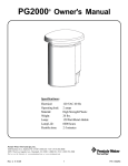
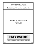
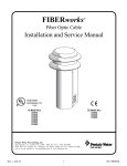
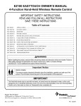
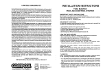
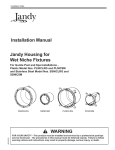
GLACIER POOL COOLERS, LLC OPERATOR INSTRUCTIONS, INSTALLATION AND SERVICE MANUAL ALL MODELS GPC 23 THROUGH GPC 280 SERIES GPC 23-280 SERIES PATENT NO: US 7,624,589 B1 MADE IN THE USA GLACIER POOL COOLERS, LLC P.O. BOX 5198 SCOTTSDALE, AZ 85261 PHONE: (480)272-7700 FAX: (866)276-2083 www.glacierpoolcoolers.com GLACIER POOL COOLERS, LLC IMPORTANT INSTRUCTIONS FOR YOUR SAFETY This product must be installed and serviced by authorized personnel, qualified in pool equipment installation. Improper installation and/or operation could cause serious injury or property damage. Improper installation and/or operation will void the warranty. When installing and using this electrical equipment, basic safety precautions should always be followed, including the following: 1. READ AND FOLLOW ALL INSTRUCTIONS BEFORE INSTALLATION! 2. WARNING: TO REDUCE THE RISK OF INJURY, DO NOT PERMIT CHILDREN TO USE THIS PRODUCT UNLESS THEY ARE CLOSELY SUPERVISED AT ALL TIMES. 3. SAVE THESE INSTRUCTIONS. DO NOT DISCARD! GIVE THIS MANUAL TO POOL OWNER!! GLACIER POOL COOLERS, LLC PO BOX 5198 SCOTTSDALE, AZ 85261 (480)272-7700 PREFACE Adequate knowledge of pool cooler maintenance and control is necessary for optimum safe performance over time. In this manual, equipment, function, operation, and checking procedures will be described as follows: CAUTIONS DURING OPERATION Keep hands and foreign objects away from fan motor and assembly at all times. Since the cooling performance will be affected by the volume of the circulating water, be sure to maintain the regulation of water flow at all times. Keep the interior of the cooler always clean and take care that no scale, calcium, salt, or debris accumulates. When the level of the water in the basin drops, air is sucked in and cavitation may develop; therefore, it is necessary to keep the water at the proper level at all times. It is important to note that the water level should rise and fall with the pump operation. DO NOT try to balance the water level as doing so will eventually result in the basin being sucked dry and WILL NOT ALLOW WATER TO YOUR POOL PUMP, WHICH IN RESULT COULD DAMAGE THIS PUMP. WARRANTY INFORMATION The Glacier Pool Cooler is sold with a limited factory warranty. A copy of the warranty is included in a plastic bag inside the cooler and on the back cover of this manual. The warranty does not cover damage caused by improper installation, operation, or field modification; or damage caused by corrosive water. See section on pool water chemistry and salt water pool disclaimer for guidelines. Glacier Pool Coolers, LLC warrants all parts to be free from manufacturing defects in materials and workmanship for a period of one year from the date of retail purchase, with the following exceptions: Commercial models on commercial pools will be covered for two years You can register your unit by emailing the following information to [email protected]: PURCHASE DATE RETAILER PURCHASED FROM MODEL NO SERIAL NO (located on fan motor plate) YOUR NAME, INSTALLED ADRESS, AND PHONE NUMBER GLACIER POOL COOLERS, LLC PO BOX 5198 SCOTTSDALE, AZ 85261 (480)272-7700 OPERATING INSTRUCTIONS CHECK THE COOLER Installer Needs To Check The Following BEFORE Installation: 1. Tighten any loose nuts and bolts on ALL areas outside of the pool cooler (visible) from top to bottom. These can come loose by vibration during shipping. 2. Tighten ALL bulkhead fittings at the bottom of the unit. This is done by tightening the union oring on the inside of the unit’s basin. 3. Make sure the unit is leveled on the surface where it is being installed. TO START AND OPERATE COOLER MANUAL OPERATION Close main drain. (This is the far left 1” line with ball valve at the bottom basin.) Turn pool pump on. Open center valve (about 10 % open) to the two o’clock position. This is the input line to the pool cooler. (Installer should marked this valve after setting) Look through hand hole cover. Sprinkler wands should be turning at a “moderate” medium speed. If sprinkler wands aren’t turning, slightly open center valve more to allow increased water flow and air out of the line which will activate wands. If sprinkler wands are moving too fast, close valve off more. (If water is splashing through the top of fan guard it is too fast.) Wait approx. 30 seconds while basin fills with water. Open right valve (about 13% open) to the two ½ o’clock position. This is the output line back to the pool. The chilled water will drain out slowly. If the water does not show it is draining open your valve a little bit more until you see it draining down. THIS IS YOUR SETTING ON THE OUTPUT LINE. You want the water to drain completely and then rise again to the sump pump float switch. Then the sump pump will turn on drain the water basin again. This is how the cooler works with water flow going up and down. DO NOT BALANCE THE WATER LEVEL, THIS WILL CAUSE OVERFLOWING OR CAVITATION. (Installer should mark valve after setting) Turn fan switch to the on position in the switch box or with your automated controls. WARNING Setting inlet and outlet lines improperly can cause large scale water loss or flooding. Special attention must be made each time cooler is operating especially after any change to pool water pressure. Glacier Pool Coolers, LLC cannot be responsible for such water loss or flooding or resulting damage. GLACIER POOL COOLERS, LLC PO BOX 5198 SCOTTSDALE, AZ 85261 (480)272-7700 IMPORTANT: OPERATE AND RUN YOUR POOL COOLER OVERNIGHT FOR MAXIMUM COOLING CAPACITY. A MINIMUM OF 10 TO 12 HOURS IS REQUIRED. WE DO NOT RECOMMEND OPERATING POOL COOLER DURING DAYTIME HOURS. THE HEAT FROM THE SUN AND DAYTIME TEMPERATURES WILL OVER POWER THE CHILLING PROCESS. TURNING THE COOLER OFF Turn the fan switch to the OFF position or turn your automated controls OFF to the chiller. Close the center and right valves and open the main drain valve and leave open until next use. THE COOLER SHOULD BE LEFT IN THIS POSITION WHEN NOT IN USE! FAILURE TO FOLLOW THESE INSTRUCTIONS COULD RESULT IN THE BURNING UP OF THE PUMP SYSTEM! During summer months of operation, you DO NOT have to open and close the valves after every chilling cycle. Your check valves in line will hold the water in the pool coolers basin and will allow your pool pump to turn on and re-cycle and prime itself for the next day use. The pool cooler will keep cycling the pool water back through to the pool. TO WINTERIZE YOUR POOL COOLER PLEASE FOLLOW THE INSTRUCTIONS ABOVE FOR TURNING OFF THE POOL COOLER. **These instructions are for manual operation. If system is automated refer to your automated system instructions. MAINTENANCE Clean Basin Open the drain at the bottom of the water basin and drain. Remove dirt and debris and clear suction holes at base of pump and basin with pool water or hose as needed. Close the drain for start of operation. Clean Fan Guard Clean leaves, pine needles, and any other debris from the top of the cooler on or around the fan guard. Check Inside Remove hand hole cover and inspect interior of cooler. Remove any debris from top of PVC filling by reaching through the hand hole cover. ALWAYS MAKE SURE COOLER IS COMPLETELY TURNED OFF BEFORE REACHING INSIDE THE UNIT! NEVER PLACE HAND INSIDE UNIT WHEN FAN MOTOR IS ON! GLACIER POOL COOLERS, LLC PO BOX 5198 SCOTTSDALE, AZ 85261 (480)272-7700 Pool Water Chemistry Failure to maintain pool water chemistry can result in rusting, corrosion, or scaling buildup on your pool cooler. The proper chemical balance in your pool water should be the following: pH level between 7.2 and 7.8 Total Alkalinity (TA) between 80-120 ppm Total Dissolved Solids (TDS) less than 2000 Salt Water Pools* Understand that salt is a corrosive mineral. Salt likes to remove ions and can take zinc away from galvanized steel and this type of chlorine is five times harder on pool equipment than regular chlorine. As such, use of a salt system may lead to the deterioration of certain materials if salt levels exceed the manufacturer’s limits. Steps should be taken to protect your pool cooler and keep it in good working operation for many years. Our units are made of reinforced fiberglass, with galvanized steel components. Homeowner or operator MUST HOSE DOWN WITH FRESH WATER REGULARLY ON THE FAN MOTOR SHAFT AND FAN MOTOR HOUSING AS WELL AS THE SPRINKLER HEAD ASSEMBLY LOCATED THROUGH THE FAN GUARD ( THIS IS THE CENTER PIECE CONNECTING THE SPRINKLER WANDS). FAILURE TO DO SO WILL CAUSE SALT RESIDUE BUILDUP AND WILL FREEZE UP THESE PARTS AND CAUSE DAMAGE. Keep these parts cleaned with fresh water regularly to reduce salt build up and rusting (from the fan motor housing and shaft to the exterior visible nuts and bolts). As with all pool equipment there should be some expectation of cosmetic effects from the corrosiveness of salt water. These cosmetic effects will not hinder the operation of the pool cooler. Glacier Pool Coolers, LLC, however, does not warranty fan motors or pumps on salt water pools due to salt corrosion or buildup. All remaining parts are fully warranted as per our limited factory warranty. FAN MOTOR MAINTENANCE Homeowner and/or operator needs to annually spray the fan motor casing with Rustoleum Paint ( color to match) to maintain the fan motor from rusting and/or corroding. This will keep the fan motor from rusting and keep its performance working for years to come. CAUTION Keep all objects off the top of the cooler and do not obstruct louver openings in cooler sides. Blocking ventilation air flow may damage the cooler and void the warranty. GLACIER POOL COOLERS, LLC PO BOX 5198 SCOTTSDALE, AZ 85261 (480)272-7700 INSTALLATION INSTRUCTIONS GENERAL REQUIREMENTS All Glacier Pool Cooler models require correct installation to assure safe and satisfactory operation. The requirements for pool coolers include the following: 1. Appropriate site location and clearances. Cooler must be installed at least 18 inches away from buildings, walls, or fences made from material that could degrade from water exposure. Our coolers are open systems that may experience some water splatter or misting. 2. Sufficient supply clean air and ventilation around and above the unit. A minimum of a 5 foot clearance above the unit is necessary to avoid condensation on the structure above. 3. Adequate water flow is required by your existing pool pump. 4. Do not locate pool cooler in an enclosed room (i.e. maintenance room, garage, utility room, equipment room). 5. SEE INSTALLATION INSTRUCTIONS DIAGRAMS FOR APPROPRIATE INSTALLATIONS. WARNING When pool equipment is located below the pool surface, a leak from any component can cause large scale water loss or flooding. Installation MUST have automated valves. Glacier Pool Coolers, LLC cannot be responsible for such water loss or flooding or resulting damage. SEE INSTALLATION DIAGRAMS FOR EXISTING AND NEW POOL SET UPS. AUTOMATION INSTRUCTIONS ARE LOCATED ON SEPARATE PAGES. ELECTRICAL POWER WIRING All GPC-23 through GPC-220 models are single phase and require electrical power from a 115V 60 Hz source. All GPC-230 through GPC-280 models are 3 phase and require electrical power from a 220/480V 60 Hz source. See installation diagrams for wiring instructions. WARNING ELECTRICAL SHOCK HAZARD. Residential pool coolers contain low voltage wiring. Commercial pool coolers contain high voltage wiring. Contact with these wires may result in severe injury or death. Wiring errors can cause improper and dangerous operation. GLACIER POOL COOLERS, LLC PO BOX 5198 SCOTTSDALE, AZ 85261 (480)272-7700 TROUBLESHOOTING EXCESS SPLATTER COMING FROM THE TOP OF THE COOLER If there is water droplets splattering out the top of the cooler you need to slow your sprinkler wands down. In order to do this simply restrict the flow of water coming into the unit by slowly turning the ball valve back on the IN line. The wands should be turning at a slower of “walking” rate of speed. As a rule of thumb both the IN and OUT valves should be positioned at about the 2 o’clock position. MY COOLER ONLY DROPPED MY POOL DOWN BY 5 DEGREES. IS THERE SOMETHING WRONG? If a desirable drop in degrees is not established within an 8-12 hour period, there may need to be some use adjustments. Always make sure that the sprinkler wands are turning at a slower or “walking” rate of speed. It is recommended that the cooler run at night when the sun is off the pool. An initial drop in temperature should be expected overnight. If the sun warms the pool back up by afternoon, just turn the system on to keep your pool refreshing. Please be reminded that all pools are different and your pool’s finish (i.e. dark bottom, pebble bottom), location (in the sun all day), and equipment location (over 15 ft. run from equipment to pool), among other variables can cause different cooling results. It may take some time to figure out what settings suit your preferences. You might need to run the cooler for a longer period of time. IS THE WATER SUPPOSED TO FILL UP IN THE BASIN AND THEN DRAIN EVERY FEW MINUTES? Yes. The cooler is designed so that the cool water collects in the basin and the internal pump system kicks on and pushes the water back into your pool. You should never try to balance the water flow as this will eventually cause cavitation in your pool pressure. DO NOT TRY TO BALANCE TO WATER LEVEL IN YOUR COOLER’S BASIN! THE LEVEL IS SUPPOSED TO GO UP AND DOWN. WHAT DO I NEED TO DO TO WINTERIZE MY COOLER? You must keep your IN and OUT valves closed and your main drain ball valve (the bottom left valve) open so the system is drained and will stay empty from rain water. If water stays in the basin over the off-season it could potentially burn up your pump. You may also want to purchase a cover or tarp to keep any leaves or debris out of the fan area and basin especially if the cooler is under or around trees or bushes. Upon start-up at the beginning of the summer season, make sure the unit is clear of debris especially around the pump. A good hose down should do the trick. SUMP PUMP IS NOT WORKING The sump pump float switch is the power switch to the pump. If the float switch is stuck and does not activate the pump, pull one side louver out and reach into the basin and see if you can manually move the float switch up to activate the pump. If the pump vibrates, there is power to it. If the water level still does not reduce in the basin then there may be some debris stuck in the impeller which is located at the bottom of the pump. Cleaning this out should solve that problem. If the float switch goes up and there is no vibration, the wiring configuration and/or power to the pump should be looked at. ALL POOL COOLERS ARE TURNED ON AND TESTED IN THE FACTORY PRIOR TO SHIPPING. GLACIER POOL COOLERS, LLC PO BOX 5198 SCOTTSDALE, AZ 85261 (480)272-7700 SPRINKLE WANDS ARE STUCK AND ARE NOT SPINNING Make sure all power is turned off to the unit. Take the hand hole cover off on the side panel of your cooler. DANGER!!! MAKE SURE YOUR FAN MOTOR IS NOT RUNNING! Reach into the hand hole to the sprinkler head assembly located in the center of the cooler. Spin the assembly clockwise to see if it is moving freely and to make sure that there is no debris in or around the wands. If there is debris clean accordingly. Our units require pressure to allow the wands to spin. You may need to increase water flow by opening the “IN” valve to the cooler to make the wands spin. COOLER IS OVERFLOWING Immediately shut the valves “IN’ and “OUT” of the cooler. Check to make sure that there is power to the pump. Follow instructions above for sump pump troubleshooting. CONTROL THE TEMPERATURE OF MY POOL Our residential coolers do not come with thermostat controls. Cooling is determined by the run time of your pool pump. If it’s too cold, cut back your hours. If it’s not cool enough, run your pump longer. Now if your pool is automated our pool cooler can integrate into your system and a temperature range can be set through your automated system. YOU MAY ALSO CONTACT OUR TECHNICAL SERVICE DEPARTMENT BY EMAILING [email protected] OR CALLING 480-272-7700. Glacier Pool Coolers, LLC and Glacier Pool Coolers is a registered trademark. All other brand names, products names or trademarks belong to their respective holders. GLACIER POOL COOLERS PARTS FAN MOTOR FRP CASING FAN ASSEMBLY SPRINKLER WAND ASSEMBLY PVC FILLING CASING SUPPORT LOUVERS PUMP SYSTEM OUTLET LINE BASIN INLET LINE MAIN DRAIN GLACIER POOL COOLERS, LLC PO BOX 5198 SCOTTSDALE, AZ 85261 (480)272-7700 BASIC PARTS LIST FOR INSTALLATION PLUMBING EXISTING POOL QTY 2 2 2 10 2 2 1 1 12" 20 FT 1 PART 2" 2 LB. JANDY CHECK VALVES 2" T-FITTINGS 2" TO 1.5" REDUCERS 90 DEGREE ELBOWS 1.5" MALE ADAPTERS (THREADED) OR NIPPLES 2" BALL VALVES - STANDARD 1" MALE ADAPTER (THREADED) OR NIPPLES 1" PLUG (THREADED) 1" PVC PIPE 2" PVC PIPE (EST. FT) 1" BALL VALVE - STANDARD NEW POOL BUILD QTY 1 1 1 5 2 1 1 1 12" 20 FT 1 PART 2" 2 LB. JANDY CHECK VALVES 2" T-FITTING 2" TO 1.5" REDUCER 90 DEGREE ELBOWS 1.5" MALE ADAPTERS (THREADED) OR NIPPLES 2" BALL VALVES - STANDARD 1" MALE ADAPTER (THREADED) OR NIPPLES 1" PLUG (THREADED) 1" PVC PIPE 2" PVC PIPE (EST. FT) 1" BALL VALVE - STANDARD ELECTRICAL EXISTING AND NEW POOL BUILD QTY PART 2 14 .5" SEAL TIGHT CONDUIT (DETERMINE FT) .5" CONDUIT CONNECTORS (water tight) GAUGE WIRE - 3 COLORS **ADDITIONAL PARTS MAY BE NEEDED FOR AUTOMATED SYSTEMS EXISTING POOL 2 - 3 -WAY AUTOMATED ACTUATOR VALVES NEW POOL 1 - 3 -WAY AUTOMATED ACTUATOR VALVE STANDARD INSTALLATION EXISTING POOL SET-UP in out 1" inlet line outlet line HEATER Ball Valves 2" Return to pool 2 lb. Check Valve Add T-Fitting 2lb. Check Valve Fitting FILTER =waterflow Skimmer/ suction Add T-Fitting PUMP main drain WARNING ELECTRICAL SHOCK HAZARD. Residential pool coolers contain low voltage wiring. Commercial pool coolers contain high voltage wiring. Contact with these wires may result in severe injury or death. Wiring errors can cause improper and dangerous operation. Glacier Pool Coolers, LLC is not responsible for improper installation or use of its equipment. 1. FIRST STEP - ADD and connect a PVC T- Fitting right after the Filter or Heater line return to the pool, then ADD your PVC pipe line. Next, ADD a 2lb.JANDY Check valve on this line, then ADD a (red or blue handle) Ball valve before the inlet. Connect this to a threaded adapter fitting (1 1/2 Male size) going to the MIDDLE inlet hole (input) to the cooler (connect and glue all parts). Use 2" pipe.(Must ADD 2" Reducer fitting after ball valve, going into cooler if using 2" pipe on install on ALL residential models). 2. SECOND STEP- ADD another adapter fitting at the right outlet hole, (output) then ADD and connect your Ball Valve FIRST, then ADD your PVC pipe line out of the cooler. NEXT, ADD a 2 lb. JANDY Check valve on this line down (closer to the pool pump) at the suction/skimmer side of the equipment set-up. Then, ADD a PVC T- Fitting at suction/skimmer line to connect this line at the pump. 3. THIRD STEP- ADD 1" plug in top hole on the left side of basin. ADD 1" threaded fitting, then a 1" Ball valve at bottom lower outlet. 4. FOURTH STEP- ELECTRICAL The pool cooler works with the pool pump power. The minimum amperage needed is a 20 amp breaker to operate the pool cooler with the pool pump. Electrical installation on a retro-fit Cooler 220v intermatic timeclock. The cooler is 110v and most pool systems operate @ 220v, therefore take the hot leg from the cooler and run it to either load on the T104R3 220v timeclock. The ground ties into the grounding lug on the bottom of the timeclock. The Neutral wire needs to be run either to the ground or to the open screw on the far left of the terminal. Run an extra piece of ground wire to the open terminal (far left, and a little offset)if you decide to use the extra terminal for the ground wire, which is preferred. Electrical installation using an Aqualink or Compool system. Installation of a Glacier Cooler on a Pentair, Jandy, Hayward or a Compool is virtually the same. First, find the primary filter pump which will be feeding the cooler. The relay has 4 screws 2 lines and 2 loads as follows from left to right....Line1 Load1 Line2 Load2. Use one of the Loads as your HOT for the Cooler, either one, but only one, you will need an available relay or add another if space is available. Take the cooler relay's (line) and wire it to either of the filter pumps load, this will keep the cooler from running without the filter pump. Ground and Neutral tie into the Grounding terminal. Each relay has a plug that must be plugged into an open Aux female socket to allow control through the automated system. When using actuators, you will need (Factory recommends one actuator per valve actuator control) otherwise both actuators can be tied together and plugged into one valve control. There are many different ways to electrically install a Glacier Cooler, depending on the needs of your customers. This product must be installed and serviced by authorized personnel, qualified in pool equipment installation. Improper installation and/or operation could cause serious injury or property damage. Improper installation and/or operation will void the warranty. AUTOMATING EXISTING POOL SET-UP in out 1" inlet line outlet line HEATER Ball Valves 2" Return to pool 3-Way Automated Actuator Valve 3-Way Automated Actuator Valve Add T-Fitting Fitting FILTER =waterflow Skimmer/ suction Add T-Fitting PUMP main drain WARNING ELECTRICAL SHOCK HAZARD. Residential pool coolers contain low voltage wiring. Commercial pool coolers contain high voltage wiring. Contact with these wires may result in severe injury or death. Wiring errors can cause improper and dangerous operation. Glacier Pool Coolers, LLC is not responsible for improper installation or use of its equipment. 1. FIRST STEP - ADD and connect a PVC T- Fitting with a 3- way actuator automated valve right after the Filter or Heater line return to the pool, then ADD your PVC pipe line. Next, then ADD a (red or blue) handle Ball valve before the inlet. Connect this to a threaded adapter fitting (1 1/2 Male size) going to the MIDDLE inlet hole (input) to the cooler (connect and glue all parts). Use 2" pipe.(Must ADD 2" Reducer fitting after ball valve, going into cooler if using 2" pipe on install on ALL residential models). DO NOT USE 1 1/2" PIPE 2. SECOND STEP- ADD another adapter fitting at the right outlet hole, (output) then ADD and connect your Ball Valve FIRST, then ADD your PVC pipe line out of the cooler. NEXT, ADD a PVC T- Fitting with 3- way actuator automated valve at suction/skimmer line to connect this line at the pump. 3. THIRD STEP- ADD 1" plug in top hole on the left side of basin. ADD 1" threaded fitting, then a 1" Ball valve at bottom lower outlet. 4. FOURTH STEP- ELECTRICAL The Glacier Pool Cooler is adaptable and can be automated with ALL systems. Installation of a Glacier Cooler on a Pentair, Jandy, Hayward or a Compool is virtually the same. You need two open relays to make it work. First, find an open relay which will be feeding the cooler and the inlet automated valve together on this relay.The relay has 4 screws 2 lines and 2 loads as follows from left to right....Line1 Load1 Line2 Load2. Use one of the Loads as your HOT for the Cooler and the other load 2 for the actuator. This turns on and opens the automated valve and at the same time it activates the power to the pool cooler. Ground and Neutral tie into the Grounding terminal. NEXT, find another open relay to connect in the second automated valve ( this is the valve at the T-fitting at the suction side of the pump). Repeat steps above for connecting. This valve needs to open up after the first aux. relay opens. ( Failure to do so, will cause air in the lines and cause cavitation of the pool pump ). Each relay has a plug that must be plugged into an open Aux female socket to allow control through the automated system. When using actuators, you will need (Factory recommends one actuator per valve actuator control) This product must be installed and serviced by authorized personnel, qualified in pool equipment installation. Improper installation and/or operation could cause serious injury or property damage. Improper installation and/or operation will void the warranty. STANDARD INSTALLATION NEW POOL SET-UP 1" Ball Valves HEATER Check Valve 2" Back to pool Add PVC T-Fitting FILTER Back to pool (designated line) Skimmer P U M P WARNING ELECTRICAL SHOCK HAZARD. Residential pool coolers contain low voltage wiring. Commercial pool coolers contain high voltage wiring. Contact with these wires may result in severe injury or death. Wiring errors can cause improper and dangerous operation. Glacier Pool Coolers, LLC is not responsible for improper installation or use of its equipment. 1. FIRST STEP - Replace to a PVC T- Fitting right after the FINAL Heater return/ or Filter return to the pool , then ADD your PVC line FIRST, a 2lb. Jandy Check valve SECOND and LAST a (red or blue handle) Ball valve on this line going to the MIDDLE inlet hole to the cooler (connect and glue all parts). Use 2" pipe (Must ADD 2" Coupling Reducer after ball valve, if using 2" pipe on install). 2. SECOND STEP - Then connect and glue your 1.5" inch Nipple PVC going out of cooler, then ADD a 2" coupling reducer to your 2" inch pipe dedicated line back to the pool. (This must be a designated line to the bottom center of the pool ). NOT ON THE SIDE WALLS. 3. THIRD STEP - ADD 1" Plug in the top hole on the left side of bottom basin. ADD 1" Ball valve (fitted) at bottom lower outlet drain. 4. FOURTH STEP - ELECTRICAL The pool cooler works with the pool pump power. The minimum amperage needed is a 20 amp breaker to operate the pool cooler with the pool pump. Electrical installation on a 220v intermatic timeclock. The cooler is 110v and most pool systems operate @ 220v, therefore take the hot leg from the cooler and run it to either load on the T104R3 220v timeclock. The ground ties into the grounding lug on the bottom of the timeclock. The Neutral wire needs to be run either to the ground or to the open screw on the far left of the terminal. Run an extra piece of ground wire to the open terminal (far left, and a little offset)if you decide to use the extra terminal for the ground wire, which is preferred. Electrical installation using an Aqualink or Compool system. Installation of a Glacier Cooler on a Pentair,Jandy, Hayward or a Compool is virtually the same. First, find the primary filter pump which will be feeding the cooler. The relay has 4 screws 2 lines and 2 loads as follows from left to right....Line1 Load1 Line2 Load2. Use one of the Loads as your HOT for the Cooler, either one, but only one, you will need an available relay or add another if space is available. Take the cooler relay's (line) and wire it to either of the filter pumps load, this will keep the cooler from running without the filter pump. Ground and Neutral tie into the Grounding terminal. Each relay has a plug that must be plugged into an open Aux female socket to allow control through the automated system. When using actuators, you will need (Factory recommends one actuator per valve actuator control) otherwise both actuators can be tied together and plugged into one valve control. There are many different ways to electrically install a Glacier Cooler, depending on the needs of your customers This product must be installed and serviced by authorized personnel, qualified in pool equipment installation. Improper installation and/or operation could cause serious injury or property damage. Improper installation and/or operation will void the warranty. AUTOMATION INSTALLATION NEW POOL SET-UP 3-Way Automated Actuator Valve 1" Ball Valves 2" Back to pool Back to pool (designated line at the bottom center) HEATER Add PVC T-Fitting FILTER Skimmer P U M P WARNING ELECTRICAL SHOCK HAZARD. Residential pool coolers contain low voltage wiring. Commercial pool coolers contain high voltage wiring. Contact with these wires may result in severe injury or death. Wiring errors can cause improper and dangerous operation. Glacier Pool Coolers, LLC is not responsible for improper installation or use of its equipment. 1. FIRST STEP - Replace to a Automated Aquator Valve PVC T- Fitting right after the FINAL Heater return/ or Filter return to the pool. then ADD your PVC line FIRST, then a (red or blue handle) Ball valve on this line going to the MIDDLE inlet hole to the cooler (connect and glue all parts). Use 2" pipe on All residential models (Must ADD 2" Coupling Reducer after 1 1/2 ' in. male adapter into inlet and outlet. 2. SECOND STEP - Then connect and glue your 1.5" inch Nipple PVC going out of cooler, then ADD a 2" coupling reducer to your 2" inch pipe dedicated line back to the pool. (This must be a designated line to the bottom center of the pool ). NOT ON THE SIDE WALLS. 3. THIRD STEP - ADD 1" Plug in the top hole on the left side of bottom basin. ADD 1" Ball valve (fitted) at bottom lower outlet drain. 4. FOURTH STEP - ELECTRICAL The Glacier Pool Cooler is adaptable and can be automated with ALL systems. Installation of a Glacier Cooler on a Pentair, Jandy, Hayward or a Compool is virtually the same. You need one open relay to make it work. First, find an open relay which will be feeding the cooler and the inlet automated valve together on this relay.The relay has 4 screws 2 lines and 2 loads as follows from left to right....Line1 Load1 Line2 Load2. Use one of the Loads as your HOT for the Cooler and the other load 2 for the actuator. This turns on and opens the automated valve and at the same time it activates the power to the pool cooler. Ground and Neutral tie into the Grounding terminal. The relay has a plug that must be plugged into an open Aux female socket to allow control through the automated system. When using actuators, you will need (Factory recommends one actuator per valve actuator control). This product must be installed and serviced by authorized personnel, qualified in pool equipment installation. Improper installation and/or operation could cause serious injury or property damage. Improper installation and/or operation will void the warranty. COMMERCIAL INSTALLATION DIAGRAM in out 1" inlet line outlet line HEATER Ball Valves Return to pool Add T-Fitting Fitting FILTER 1. FIRST STEP - ADD and connect a PVC T- Fitting right after the Filter or Heater line return to the pool, then ADD your PVC pipe line. Next, ADD a Ball valve before the inlet. Connect this to a threaded adapter fitting ( Check cooler model to see fitting size ) going to the MIDDLE inlet hole (input) to the cooler (connect and glue all parts). Use appropriate pipe by cooler model and on site plumbing. ( SEE TECH SPEC. SHEET ) 2. SECOND STEP- ADD another adapter fitting at the right outlet hole, (output) then ADD and connect your Ball Valve FIRST, then ADD your PVC pipe line out of the cooler toward the suction/skimmer side of the equipment set-up. Then, ADD a PVC T- Fitting on the suction/skimmer line near the pump, then connect line. ( If the Facility has a surge tank, then this line can drop down below the water line into this tank as the chill water return ). 3. THIRD STEP- ADD 1" plug in top hole on the left side of basin. ADD 1" threaded fitting, then a 1" Ball valve at bottom lower outlet. 4. FOURTH STEP- ELECTRICAL MODELS GPC- 23 TO GPC- 220 requires hook up to a single phase seperate 25 Amp breaker. MODELS GPC-230 TO GPC- 280 require 3-Phase 25 Amp breaker. Each 3Phase installation will require single pole to 3- Phase contactor for tie in from Motor to Sump Pump and Thermostat connections. The facility needs to have 3- Phase Breaker and Automatic Shut-off switch ready available for POOL COOLER hook up. Wire hot out of breaker to the contactor. When the a319 Thermostat calls for cooling it pulls in the contactor to supply voltage to the FAN motor and sump pump. The T-Stat controls the Fan motor on & off. The sump pump is single phase 115V. LN 1 FAN MOTOR LN 2 3 POLE TO 1 POLE CONTACTOR GND Skimmer/ suction Add T-Fitting PUMP main drain WARNING ELECTRICAL SHOCK HAZARD. Residential pool coolers contain low voltage wiring. Commercial pool coolers contain high voltage wiring. Contact with these wires may result in severe injury or death. Wiring errors can cause improper and dangerous operation. Glacier Pool Coolers, LLC is not responsible for improper installation or use of its equipment. SUMP PUMP LN 2 LN 3 LN 3 =waterflow LN 1 TSTAT 1 PH 3 PH 25 AMP BREAKER GLACIER POOL COOLERS, LLC LIMITED WARRANTY Glacier Pool Coolers, LLC warrants all parts to be free from manufacturing defects in materials and workmanship for a period of one year from the date of retail purchase, with the following exceptions: Commercial models on commercial pools will be covered for two years This warranty is limited to the first retail purchaser, is not transferable, and does not apply to products that have been moved from their original installation sites. The liability of Glacier Pool Coolers, LLC shall not exceed the repair or replacement of defective parts and does not include any costs for labor to remove and reinstall the defective part, transportation to or from the factory, and any other materials required to make the repair. This warranty does not cover failures or malfunctions resulting from the following: Failure to properly install, operate or maintain the product(s) in accordance with our published Installation and Operation Manual provided with the product(s). The workmanship of any installer of the product(s). Not maintaining a proper chemical balance in your pool water [pH level between 7.2 and 7.8, Total Alkalinity (TA) between 80 and 120 ppm, Total Dissolved Solids (TDS) less than 2000]. Abuse, alteration, accident, fire, flood, lightening, rodents, insects, debris, negligence, or acts of God. Scaling, freezing, or other conditions causing inadequate water circulation. Use of non-factory authorized parts or accessories in conjunction with the product(s). Chemical contamination or improper use of sanitizing chemicals. Incorrect wire runs, improper electrical supply, collateral damage caused by improper operation and maintenance. Damage or corrosion from, or buildup of salt on fan motors, pumps, or any other moving or non-moving parts resulting from a salt chloronation/generating pool. See salt pool disclaimer in Operations Manual. Damage from shipping/freighting from manufacturer. LIMITATION OF LIABILITY: This is the only warranty given by Glacier Pool Coolers, LLC. No one is authorized to make any other warranties on Glacier Pool Coolers, LLC’s behalf. THIS WARRANTY IS IN LIEU OF ALL OTHER WARRANTIES, EXPRESSED OR IMPLIED, INCLUDING BUT NOT LIMITED TO ANY IMPLIED WARRANTIES OF FITNESS FOR A PARTICULAR PURPOSE AND MERCHANTABILITY. GLACIER POOL COOLERS, LLC EXPRESSLY DISCLAIMS AND EXCLUDES ANY LIABILITY FOR CONSEQUENTIAL, INCIDENTAL, INDIRECT, OR PUNITIVE DAMAGES FOR BREECH OF ANY EXPRESSED OR IMPLIED WARRANTY. This warranty gives you specific legal rights. You may also have other rights which vary by state of province. WARRANTY CLAIMS: For prompt warranty consideration, contact your dealer and provide the following information: Proof of purchase, model number, serial number, and date of installation. The installer will contact the factory for instructions regarding the claim. If the dealer is not available, you can find an authorized service provider in your area by visiting www.glacierpoolcoolers.com or by calling our technical support department at 480.272.7700. All returned parts must accompany a return authorization number issued by Glacier Pool Coolers, LLC and require inspection prior to a warranty being fulfilled. Glacier Pool Coolers, LLC has the right to replace any warranty claim with a refurbished part. All replacement parts are warranted for the initial one year from date of purchase. GLACIER POOL COOLERS, LLC . PO BOX 5198 . SCOTTSDALE, AZ 85261 PH: 480-272-7700 . FAX: 866-276-2083