1
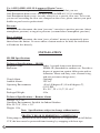
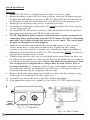
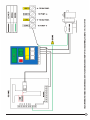
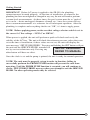
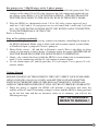
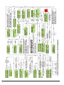
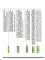
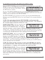
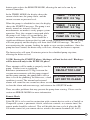
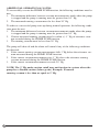
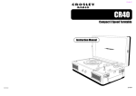
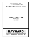
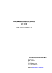
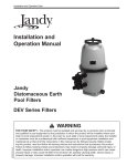
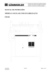
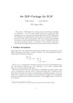
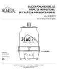
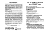
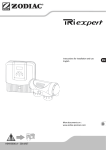
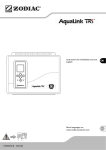
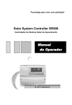
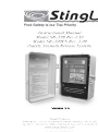
Ver
s
i
on3.
5
Table of Contents
Section
Page
INTRODUCTION.......................................................................2
IMPORTANT INFORMATION.................................................3
INSTALLATION........................................................................ 4
OPERATING INSTRUCTIONS...............................................16
TROUBLESHOOTING
CALIBRATION ISSUES (SR500)........................................23
CALIBRATION ISSUES (SR500PS)....................................34
ERROR CODES....................................................................39
CALIBRATION INSTRUCTIONS SR500.............................27
OPTIONAL EQUIPMENT........................................................43
PARTS LIST..............................................................................43
CONTACT INFORMATION.....................................................44
1
INTRODUCTION
Thank you for choosing to install the Stingl-Switch Model SR-500 on your
swimming pool, hot tub, or spa. The enclosed information is designed to give you
years of safe operation of your Stingl-Switch. Please closely review this important
product information.
The Stingl-Switch Model SR-500 works by monitoring the vacuum on the influent
side of the pool or spa pump. Whenever a blockage occurs in the pool drain or
skimmers, the sudden rise in vacuum will cause the Stingl-Switch to immediately
shut down pump operation and activate an audible alarm. The pump will remain off
and the audible alarm will sound until manually reset.
The Stingl-Switch Model SR-500 provides a 30-minute Maintenance/Cleaning
mode to allow pool vacuuming. Normally, the high vacuum generated by pool
vacuuming would cause the Stingl-Switch to sense an entrapment condition and shut
off the pump. However, in the Maintenance/Cleaning mode, the Stingl-Switch is
DEACTIVATED and the pump is allowed to run under a high vacuum situation.
WARNING: DURING MAINTENANCE/CLEANING MODE VACUUM IS
NOT MONITORED. A BLOCKAGE WILL GO UNDETECTED DURING
THE 30-MINUTE CYCLE, INCREASING THE RISK OF ENTRAPMENT.
*No bathers should be allowed in pool/spa while Maintenance Mode is in use.
To prevent the system from being left accidentally in Maintenance/Cleaning mode,
the audible alarm will be activated whenever the switch is in this mode. The pool,
hot tub, or spa should not be used or left unattended while servicing or cleaning in
the maintenance mode.
The Stingl-Switch Model SR-500 is designed to be easily retrofitted on all existing
pools, hot tubs, and spas, and is easily installed during new pool and spa
construction.
2
Use ANSI/ASME A112-19.8 approved Drain Covers
To prevent hair entrapment we STRONGLY recommend that you use
Anti-Entrapment drain covers that meet ANSI/ASME A112-19.8 standards.
Anti-Entrapment drain covers are only effective to a specific flow rate. To be sure
you are not exceeding the flow rate stamped on the cover, please contact your pool
builder or pool service professional.
Pressure
As used in this document, the term “pressure” can refer to positive pressure (above
atmospheric pressure) or negative pressure (vacuum below atmospheric pressure.)
Press a button
As used in this document, the term “press a button” means to momentarily press
then release the button. In cases where a button needs to be held, the instruction
will indicate this directly.
INSTALLATION
SR-500 Specifications
Technical Specifications – SR-500
Response Time:
under 3 seconds from event detection
Enclosure:
NEMA 3R (Intended for outdoor use. Provides a
degree of protection against falling rain and ice
formation. Meets rod entry, rain, external icing,
and rust-resistance design tests.)
Visual Alarm:
Optional
Audible Alarm:
24V AC
Operating Environment:
-40 to 140 degrees F (-40 to 60 degrees C),
0-95% RH,
Size:
H = 9.0”; W = 5 1/2”; D =4.0”
Packaged Weight:
4 lbs.
Technical Specifications – Remote Alarm
Voltage: 24 V AC
Operating Environment: Suitable for Indoor\Outdoor
Size: H = 9.0”; Dia. = 3.0”
Weight: 1 lbs.
Note: Specifications subject to change without notice.
PROTECT HOSE IN FREEZING CONDITIONS!!!
If the pump is operated in an area where the ambient air temperature can fall below
32˚F, the hose must be protected from freezing by wrapping with heat tape.
4
Pre-Installation Checklist
1.
2.
3.
4.
5.
6.
7.
8.
All Ports (drains, skimmers, vacuum lines, etc.) MUST BE FREE OF
DEBRIS PRIOR TO INSTALLATION. Clogged ports will disrupt the
normal vacuum level.
Backwash or otherwise clean filter as per manufacturer specification.
Clean pump trap basket and skimmer basket(s).
Inspect main drain cover. (Also Inspect Spa Drain if present) Drain covers
must be free of obstruction, securely fastened w/ stainless steel screws, and in
sound condition w/ no cracks or breaks.
Repair any leaks in circulation system before installation. Leaks will cause
the formation of air bubbles that disrupt the normal vacuum level.
Set all valves to normal operating position. Vacuum port valve(s) should be
closed and dedicated vacuum line(s) should be capped in pool. Installations
with pool and spa combinations, with a single pump, we recommend you
consult your pool builder or service professional about closing the spa drain
line during regular filtration.
Pump should be run prior to installation and left in fully primed condition.
ALL CHECK VALVES MUST BE REMOVED FROM SYSTEM!
Check values can cause a dangerous vacuum condition to remain even after
pump shut off.
❑
❑
❑
❑
❑
❑
❑
❑
BREAKER
PANEL
OR
SR-500
PUMP
CONTROLLER
CONDUIT
VACUUM HOSE
TO WATER JETS
TO MAIN DRAIN
LINT
TRAP
PUMP
MOTOR
DRAIN PLUG
Fig.1: System Diagram
5
Switch Installation
Mounting
1. Mount the SR-500 in a suitable location within 8 feet of the pump.
2. Before mounting, remove SR-500 from its plastic enclosure by depressing tab
in upper left and pulling top portion of SR-500. Slide SR-500 out from the top.
At this point, record the serial number of your SR-500 on the warranty card.
3. Mount plastic enclosure using screws & anchors provided.
4. Install the hose fitting provided in the 1/2” inner knockout below the vacuum
sensor. (Refer to Fig.2)
5. Re-install SR-500 into plastic enclosure. Slide the bottom of SR-500 into box;
then press upper portion until SR-500 snaps into place.
6. NOTE: Top portion of hose must be mounted onto vacuum sensor prior to
connecting lower end to pump trap. DO NOT connect the hose to the pump
until after successfully zeroing the sensor in service mode. The sensor must
be open to atmosphere to zero properly.
7. Feed the vacuum hose through the hose fitting and connect to the vacuum
sensor. Insure hose is snug onto vacuum sensor. Tighten the hose fitting
securely to provide strain relief for the hose. Attach hose clamp (included) for
additional strain relief (Refer to Fig.2.A). The vacuum hose MUST exit the box
straight down without bends or kinks.
8. When routing the hose take care to avoid high-traffic areas where the hose can
be stepped on or tripped over. Zip-tying the hose to the pump electric conduit is
a good option. Excess hose can be trimmed, but under no circumstances shall
the existing hose be lengthened or a longer hose be used. Protect hose in
freezing conditions by wrapping with heat tape. If the pump is operated in an
area where the ambient air temperature can fall below 32˚F, the hose must be
protected from freezing by wrapping with heat tape.
9. Remove drain plug from pump trap. Install in its place the flare adapter, using
Teflon tape (not included) to ensure a good seal.
10. Attach the free end of the hose to the flare adapter and tighten.
11. If no pump drain plug exists, plumb in a tee with a 1/4” FPT reducer bushing.
REMOVE
INNER
KNOCKOUT
Fig. 2: 1/2” Knockout
Fig. 2.A: Hose Clamp
6
Wiring the SR500/SR500PS
NOTE: THE STINGL-SWITCH CANNOT BE USED/RELIED ON AS AN ELECTRICAL DISCONNECT MEANS. A SEPARATE DISCONNECT MEANS MUST
BE PROVIDED. A CERTIFIED ELECTRICIAN IN ACCORDANCE WITH THE
NATIONAL ELECTRICAL CODE MUST COMPLETE ALL ELECTRICAL
WORK.
The voltage selector switch on the right side of the metal case MUST BE SET to match the
incoming power. Damages to the unit due to improper power input WILL NOT be covered
by warranty. The unit is set to 230 volts at the factory, this will also be the correct setting
for 208 volt applications. For 110/115/120 volt pumps, set the selector switch to 115v.
Line Voltage Option 1
High Voltage 120/240V Single Phase 3 HP Pumps (20AMP) or less
(See Fig. 3 for terminal locations)
1. Determine the operating input voltage of the pump, 120V or 240V. Set the red
input switch (located on the right side of SR-500) accordingly.
2. Wire incoming voltage to line terminals (#10 & #12)
3. Wire pump to load terminals (#9 & #11)
4. Connect line & load grounds to the green ground pigtail with wire nut.
5. For this scenario see Drawing 1 or 2
Line Voltage Option 2
High Voltage 240/480/600 Triple Phase 3.5 HP pumps (20AMPS) or greater.
1. Set the red input switch (located on the right side of SR-500) to 115V
2. For this scenario see Drawing 3
Low Voltage (See Fig. 3 for terminal locations)
1. Heater delay circuit (fireman’s switch) – connect heater delay circuit to contacts
(#3 & #4) on
terminal strip. NOTE: Heater delay must be enabled in set up menu – see
operating instructions
2. Remote powered alarms can be connected to terminals (#5 & #6), or the SR500 can power 24V alarms by jumping terminals (#6 & #7), and wiring alarm
to terminals (#5 & #8).
3. Remote interfaces such as Jandy® or ComPool®, pneumatic or solid-state
controls and external timer systems are connected to terminals (#1 & #2).
NOTE: The remote mode must be enabled in the on/start menu for remote
interfaces to operate properly.
Fig. 3: Terminal Diagram
7
8
9
10
11
12
13
14
15
OPERATING INSTRUCTIONS
Front Panel
The SR-500 front panel features a two-line by 16-character backlit liquid crystal
display and six momentary pushbutton switches implemented in a membrane label.
Switches
OFF/STOP – Immediately stops pump operation. Also silences any active alarms.
ON/RUN – Toggles between timed, continuous run, and remote modes.
MAINT/CLEAN – Initiate Maintenance/Cleaning mode, where the pump will
operate continuously for 30 minutes.
WARNING: DURING MAINTENANCE/CLEANING MODE VACUUM IS
NOT MONITORED. A BLOCKAGE WILL GO UNDETECTED DURING
THE 30-MINUTE CYCLE, INCREASING THE RISK OF ENTRAPMENT.
SET – Used to initiate set-up modes for time, date, and pump operating schedule.
+/YES and -/NO – Used to answer yes/no questions, and increment or decrement
the value of a displayed selection, (i.e. date and time).
Fig. 5: Membrane Switch
16
Getting Started
IMPORTANT! Before AC power is applied to the SR-500, the plumbing
connection must be made properly. At the time of installation, or whenever the
plumbing has been reconfigured or changed in any way, the unit will need to perform
vacuum level measurements. At these times, the pool system must be as “perfect”
as it can be – drains unclogged, skimmers cleaned, etc., since the system will use
these vacuum measurements as a reference for all subsequent operation. After the
plumbing is complete and everything checks out “OK”, it’s time to apply power.
NOTE: Before applying power, make sure that voltage selector switch is set to
the correct AC line voltage – 115VAC or 230VAC.
When power is applied, the unit will perform a quick self-check and verify the
stability of the AC line. The unit will check the reference pressure values that were
set at the time of installation; if these values are not set, the unit will display the
error message “SET-UP REQUIRED.” Pressing and holding the SET button will put
the unit into the SERVICE MODE, intended for
SET-UP REQUIRED!
use by service technicians only. Pressing any
REFER
TO MANUAL
other button will have no effect.
Once the clock is set and the pump is primed, the unit is ready for normal operation.
NOTE: The unit must be properly set-up in order to function: failing to
successfully perform the PRIME PUMP function will prevent the unit from
operating. Until the PRIME PUMP function is executed, you will continue to
see the ‘SET-UP REQUIRED’ message when you attempt to exit the SERVICE
MODE. No other operating modes may be selected.
17
Wiring
NOTE – THE SR500 CANNOT BE USED/RELIED UPON AS A SERVICE DISSCONNECT MEANS. A SEPARATE DISCONNECT MEANS (SUCH AS A CIRCUIT BREAKER) MUST BE PROVIDED. A CERTIFIED ELECTRICIAN IN
ACCORDANCE WITH THE NATIONAL ELECTRICAL CODE MUST COMPLETE ALL ELECTRICAL WORK.
Power Terminals are on the bottom right of the unit, and are labeled Line 1, Line 2,
(incoming voltage) and Load 1, Load 2 (power output to pump or contactor)
BEFORE TURNING ON THE POWER TO THE UNIT, VERIFY YOUR PUMP
OPERATING VOLTAGE (120 OR 240 VOLTS) AND SET THE VOLTAGE
SELECTOR SWITCH ON THE RIGHT SIDE OF THE SR500 ACCORDINGLY.
UNITS DAMAGED BY IMPROPER POWER INPUT WILL NOT BE COVERED
BY WARRANTY!
For Single Phase pumps, 120 or 240 volts, up to 3 Hp or 20 amps.
1. Wire incoming voltage to Line 1 and Line 2. (#10 and # 12) 120 VOLT INSTALLATIONS – THE NEUTRAL BUSS MUST BE GROUNDED TO THE
GROUND BUSS IN THE SUPPLY PANEL.
2. Wire pump leads to Load 1 and Load 2. (#9 and #11) 120 VOLT INSTALLATIONS
MUST USE BOTH LOADS CONNECTED TO BOTH TERMINALS OF THE
MOTOR.
3. Connect panel and motor grounds to the green ground pigtail with a wire nut.
Refer to Drawing 1 or 2
18
For pumps over 3 Hp/20 amps, or for 3 phase pumps
1. Pump voltage must be carried by an external contactor rated for the pump load. Coil
voltage can be either 120 or 240 volts, however, the coil voltage must match the output voltage of the SR500. 120 VOLT INSTALLATIONS – THE NEUTRAL BUSS
MUST BE GROUNDED TO THE GROUND BUSS IN THE SUPPLY PANEL.
2. Wire the SR500 to a dedicated circuit, 120 or 240 volts, power input to Line 1
and Line 2 (#10 and # 12) and power out to coil from Load 1 and Load 2 (#9 and
#11) 120 VOLT INSTALLATIONS MUST USE BOTH LOADS CONNECTED
TO BOTH TERMINALS OF THE COIL.
Refer to Drawing 3
Low or No voltage terminals.
1. Remote SW input (#1 and #2) are dry contacts for remotely controlling the startup of
the SR500 in Remote Mode, such as when used with a remote control system (Jandy
or ComPool) Open = pump off, Closed = pump on
2. Heater Delay circuit – (#5 and #6) or Fireman’s switch. Wire to the delay or safety
circuit of your heater to shut it down 15 minutes before the pump. HEATER DELAY
MUST BE ENABLED IN SERVICE MODE DURING CALIBRATION.
3. Alarm – dry contact that closes while the SR500 is in an alarm state or in maintenance
mode. Use in conjunction with the 24 volt output for remote alarms.
4. 24 volt alarm output (#7 and #8) provides a 24 volt output. Use to power 24 volt
remote alarms.
Getting Started
BEFORE TURNING ON THE POWER TO THE UNIT, VERIFY YOUR PUMP OPERATING VOLTAGE (120 OR 240 VOLTS) AND SET THE VOLTAGE SELECTOR
SWITCH ON THE RIGHT SIDE OF THE SR500 ACCORDINGLY. UNITS DAMAGED BY IMPROPER POWER INPUT WILL NOT BE COVERED BY WARRANTY!
1. When the power is applied, the SR500 will perform a self-check and verify the
stability of the AC input. If incoming voltage is correct and the SR500 is being powered
up for the first time and has no reference values in it’s memory, you will see the
following message:
SET UP REQUIRED
REFER TO MANUAL!
19
By pressing and HOLDING the SET button for 5 seconds, Service Mode can be
accessed and the SR500 can be calibrated. Wait until the screen changes from:
to
SET UP MODE RELEASE FOR NEXT
SERVICE MODE TECHNICIAN ONLY
Then release the SET button. The screen will
immediately change to:
FIRMWARE VERSION
1.10 XX/XX/XX
Push SET again and the screen will change to:
INITIALIZE UNIT?
FORMAT EE? Y/N
Pushing the YES button automatically formats the
EEPROM and Microprocessor, and the screen
will read:
INIT SUCCESFULL!
SET TO CONTINUE
Push the SET button to continue calibration.
Screen will read:
SET SENSOR ZERO
AT 1 ATM? Y/N
Pushing the YES button will automatically zero
the sensor based on your local atmospheric pressure.
(the hose should be removed from the sensor during
the zeroing procedure) The screen will read:
PLEASE WAIT...
XX.XX “Hg
while the sensor zeros, the level displayed should
be within +/- 1” of zero. If so, screen will display:
ZERO SUCCESFULL!
SET TO CONTINUE
Push the SET button to continue calibration. If you
see:
CANNOT SET ZERO!
SET TO CONTINUE
Refer to the section “Troubleshooting calibration
issues” The screen will read:
PRIME POOL? Y/N
PUMP RUNS 60 SEC.
FIRST, feed the hose through the hose fitting in the box and GENTLY slide the hose onto
the sensor until it is against the top of the sensor fitting. Tighten the provided clamp (not
too tight!) to prevent leakage. Then tighten the hose fitting for additional strain relief.
THEN you can remove the plug from the Hair and Lint Trap drain port and install the adaptor fitting (1/4” NPT x 3/8” flare) in it’s place, using Teflon tape to prevent leakage. (please
put the drain plug where it can be accessed later if needed) Then attach the brass end of the
hose to the adapter fitting. (If the system may possibly encounter freezing conditions, the
hose should be protected from freezing with heat tape) Once the hose connection
20
is complete, prime the pump by filling the trap with water, insure that all valves are set for normal operational, and clean the filter and all baskets. When the system is ready to operate, push
the YES button to start the pump, and the screen will read:
FULL PRIME? Y/N?
RUNNING XX.XX “Hg
and the current running vacuum level is displayed. It is important at this time that the pump
achieve a full prime and is running normally to insure accurate calibration. If it takes more than
60 seconds for the pump to catch prime, hit the YES button again to restart the pump for another 60 seconds. Once the pump is running at full head, and the vacuum level on the screen has
stabilized (1/2” to 1” of fluctuation is normal) press the YES button again WHILE THE PUMP
IS STILL RUNNING to immediately stop the pump and save the current vacuum values to the
memory.
The resting or stopped vacuum level will be
displayed.
If you see this error:
refer to the section “Troubleshooting calibration
issues”
PLEASE WAIT...
XX.XX”Hg
DELTA-P TOO LOW!
SET TO TRY AGAIN
Once the SR500 has saved the vacuum parameters,
the screen will read:
REFERENCE VACUUM
DELTA-P XX.XX “Hg
record this value for future reference. Push the SET
button, screen will read:
REFERENCE VACUUM
STOPPED XX.XX “Hg
record this value for future reference. Push the SET
button, screen will read:
REFERENCE VACUUM
RUNNING “Hg
record this value for future reference. Push the SET
button, screen will read:
VACUUM CUTOFF AT
03” ABOVE REF Y/N?
21
This is the upper vacuum threshold, or how much of a vacuum spike will register as an
alarm. The factory default setting is 3” above the running reference, this should not be
changed without factory consultation. Press the SET button to continue. Screen will read:
HEATER DELAY?
Y/N NO
enable the heater delay circuit here by pressing the YES button. Press the SET button to
continue. Screen will read:
DEFAULT RUN
MODE: NONE
This is how the SR500 will return to service after a power outage. This setting should correspond with the mode you will regularly use. Setting the Default run mode to either Timed
or Cont. will disable Remote mode. Setting the Default run mode to Remote mode disables
both Timed and Cont. modes. After setting the Default run mode to the proper setting, press
the SET button again, screen will read:
FIRMWARE VERSION
1.10 XX/XX/XX
Press the OFF button to exit Service Mode.
22
TROUBLESHOOTING CALIBRATION ISSUES
This message indicates that the sensor was not
able to calibrate within 1” of zero. The hose
MUST be disconnected from the sensor in order
for the sensor to properly zero.
CANNOT SET ZERO!
SET TO CONTINUE
A reading of 20 to 30 psi while trying to zero the sensor is usually indicative of
water in the sensor body. Disconnect the hose from the sensor and allow 24 to 36
hours for it to dry. Connect the hose to the sensor FIRST, then to the pump, to airlock the hose and prevent water form entering the sensor.
DO NOT attempt to dry the sensor by inserting foreign objects into the tube, you
will damage the sensitive diaphragm inside. If the sensor will not zero after 36 hours
open to atmosphere, call our Technical Department for assistance.
This message will be displayed if the SR500 did
DELTA-P TOO LOW!
not register a difference of 1” or greater between
SET TO TRY AGAIN
the Stopped vacuum level and the Running vacuum level. Several scenarios can cause this error:
1 The pump was not fully primed when the Prime Pump function was ended,
resulting in less than 1” Delta-P.
2 The hose is connected to the pressure side of the pump. If the screen reading
roughly matches your filter tank pressure, this means you are sensing the pressure side of the pump. See Fig. X - Hose Mounting.
It is possible for an unseen check valve (or a pre-existing obstruction in a suction
line) to cause residual vacuum to remain in a line after the pump shuts off. If your
vacuum does not drop significantly while “please wait” is displayed after ending the
Prime Pump function, there may be a check valve in the line underground
ON/RUN MODES for SR500 rev. 1.10
Pushing the “on/run” button scrolls through three possible run modes:
1 push = Timed mode. The SR500 will run the timed cycle set in setup mode
2 pushes = Continuous mode. The SR500 will run the pump 24hours/7days.
3 pushes = Remote mode. The SR500 will only operate by closing the remote sw
input circuit.
23
TROUBLESHOOTING
Notes on System Error 11 for new installations
1 – The SR500 is equipped with 2 relays to pass power to the pump, these relays switch every
time the SR500 starts. A REAL Error 11 means that one (or both) of the relays is/are fused
shut.
A “Fake” Error 11 can be either electrically or hydraulically reproduced.
Electrically reproduced: Pump will only run for 5 seconds three times, then gives Error 11.
1 – For either 115 volt pumps or contactors with 115 volt coils, an Error 11 can mean two
things a) that the neutral buss is not grounded to the ground buss in the main panel, or b) one
load has been left open.
To test the ground/neutral connection w/o going into the main panel, remove the neutral from
Line 2. Replace it with a pigtail from Line 2 to the ground from the motor and the ground
from the SR500. If this eliminates the Error 11, the neutral buss is not grounded to the ground
buss. (if it is not per code in your jurisdiction to ground the 2 busses together, you have no
choice but to change your pump motor or contactor coil to 230 volt)
Running a neutral directly to the pump, bypassing Load 2 (open) will also cause an Error 11.
Both Load 1 and Load 2 must be connected to both motor terminals or both coil terminals
Hydraulically reproduced: Pump will run for 30 seconds one time, then give Error 11, or will
run for 30 second three times and Give Error 11. This can be caused by a hydraulic condition or inaccurate data in the SR500 memory. These cases are rare but can happen, especially in suction lift systems. In these cases Stingl Products recommends contacting our
Technical Department for further assistance.
ERROR 17
If The SR500 tries to start 3 times and does not register a vacuum level consistent with it’s
stored values, it will enter an alarm state and display “Error 17”. In a new installation this
error could either mean the initial calibration was incorrect ( Pump not at full prime or valve
settings incorrect) Re-calibrate the unit, insuring that the valves are set for normal operation
and that the pump runs at a full head during the prime pump phase of service mode.
An SR500 that has been running for a week or more that displays Error 17 could indicate
a change in the starting vacuum level due to normal maintenance issues, such as debris in
the baskets or a dirty filter. If there are no apparent blockages in any of the baskets and the
filter is in good working order and displaying normal operating pressure, check the valve
settings to insure they are still in the normal operating positions. If the error persists, you
may have a blockage in the suction line(s) (higher vacuum) or debris in the pump impeller
(lower vacuum). Also, persistent Error 17 for lower vacuum levels can also indicate problems with filter media (old sand, old cartridge, greasy D.E. grids)
If no problems can be associated with a different vacuum level, re-calibrate the unit by running the Prime Pump function in Service Mode.
24
25
26
CALIBRATION INSTRUCTIONS FOR SR500 POOL/SPA
COMBINATION UNIT REV. 2.00
1. Before mounting, remove the SR500 from it’s plastic enclosure by depressing the
tab in upper left and pulling the top of the unit forward. Slide the SR500 out
toward the top. At this point, record the serial number of your SR500 on the
warranty card.
2. Mount plastic enclosure using screws and anchors provided, in a suitable location
within 8 feet of the pump.
3. Install the hose fitting provided in the bottom left 1/2” knockout below the
vacuum sensor.
4. Re-install the SR500 into the plastic enclosure, sliding the bottom in first and
pushing the top until the SR500 snaps into place.
5. Feed the vacuum hose through the fitting, but do not attach the hose to the sensor
at this time. The sensor will need to be open to atmosphere to properly zero.
6. Freezing conditions: If you are operating your pump in conditions where the
ambient air temperature will drop below 32* F., the hose must be wrapped with
heat tape to prevent it from freezing!
Figure 2 – box bottom
Wiring
NOTE – THE SR500 CANNOT BE USED/RELIED UPON AS A SERVICE DISSCONNECT MEANS. A SEPARATE DISCONNECT MEANS (SUCH AS A CIRCUIT BREAKER) MUST BE PROVIDED. A CERTIFIED ELECTRICIAN IN
ACCORDANCE WITH THE NATIONAL ELECTRICAL CODE MUST COMPLETE ALL ELECTRICAL WORK.
Power Terminals are on the bottom right of the unit, and are labeled Line 1, Line 2,
(incoming voltage) and Load 1, Load 2 (power output to pump or contactor)
BEFORE TURNING ON THE POWER TO THE UNIT, VERIFY YOUR PUMP
OPERATING VOLTAGE (120 OR 240 VOLTS) AND SET THE VOLTAGE
SELECTOR SWITCH ON THE RIGHT SIDE OF THE SR500 ACCORDINGLY.
UNITS DAMAGED BY IMPROPER POWER INPUT WILL NOT BE COVERED
BY WARRANTY!
For Single Phase pumps, 120 or 240 volts, up to 3 Hp or 20 amps.
1. Wire incoming voltage to Line 1 and Line 2. (#10 and # 12) 120 VOLT
27
2. Wire pump leads to Load 1 and Load 2. (#9 and #11) 120 VOLT INSTALLATIONS
MUST USE BOTH LOADS CONNECTED TO BOTH TERMINALS OF THE
MOTOR.
3. Connect panel and motor grounds to the green ground pigtail with a wire nut.
Refer to Drawing 1 or 2
For pumps over 3 Hp/20 amps, or for 3 phase pumps
1. Pump voltage must be carried by an external contactor rated for the pump load.
Coil voltage can be either 120 or 240 volts, however, the coil voltage must match
the output voltage of the SR500. 120 VOLT INSTALLATIONS – THE NEUTRAL BUSS MUST BE GROUNDED TO THE GROUND BUSS IN THE SUPPLY PANEL.
2. Wire the SR500 to a dedicated circuit, 120 or 240 volts, power input to Line 1
and Line 2 (#10 and # 12) and power out to coil from Load 1 and Load 2 (#9 and
#11) 120 VOLT INSTALLATIONS MUST USE BOTH LOADS CONNECTED
TO BOTH TERMINALS OF THE COIL.
Refer to Drawing 3
Low or No voltage terminals.
1. Remote SW input (#1 and #2) are dry contacts for remote operation. Use to control the
SR500ps via a remote system (Jandy, etc.) or remote timer mechanism. Open = pump
off/Closed = pump on
2. Pool/Spa input (fireman’s switch #3 and #4) are dry contacts inputs to switch the
SR500ps from pool mode to spa mode and back. WIre to an auxililary relay in
the remote system slaved to the spa mode. Open = pool mode/Closed = spa mode
3. Heater Delay circuit – (fireman’s switch #5 and #6) wire into heater safety circuit
to shut off heater 15 minutes before the pump. Heater delay must be enabled in
Service Mode.
4. Alarm output (#7 and #8) dry contact circuit that closes when the SR500ps enters
an alarm state or is running in Maintenance Mode. Use in conjuction with a
remote alarm stack.
Getting Started
BEFORE TURNING ON THE POWER TO THE UNIT, VERIFY YOUR PUMP
OPERATING VOLTAGE (120 OR 240 VOLTS) AND SET THE VOLTAGE SELECTOR
SWITCH ON THE RIGHT SIDE OF THE SR500 ACCORDINGLY. UNITS DAMAGED BY IMPROPER POWER INPUT WILL NOT BE COVERED BY WARRANTY!
1. When the power is applied, the SR500 will perform a self-check and verify the stability of the AC input. If incoming voltage is correct and the SR500 is being powered up
for the first time and has no reference values in
SET UP REQUIRED
it’s memory, you will see the following message:
REFER TO MANUAL!
28
By pressing and HOLDING the SET button for 5 seconds, Service Mode can be
accessed and the SR500 can be calibrated. Wait until the screen changes from:
to
SET UP MODE RELEASE FOR NEXT
SERVICE MODE TECHNICIAN ONLY
Then release the SET button. The screen will
immediately change to:
FIRMWARE VERSION
2.00 XX/XX/XX
Push SET again and the screen will change to:
INITIALIZE UNIT?
FORMAT EE? Y/N
Pushing the YES button automatically formats the
EEPROM and Microprocessor, and the screen
will read:
Push the SET button to continue calibration.
Screen will read:
INIT SUCCESFUL!
SET TO CONTINUE
SET SENSOR ZERO
AT 1 ATM? Y/N
Pushing the YES button will automatically zero
the sensor based on your local atmospheric pressure.
(the hose should be removed from the sensor during
the zeroing procedure) The screen will read:
PLEASE WAIT...
XX.XX “Hg
while the sensor zeros, the level displayed should
be within +/- 1” of zero. If so, screen will display:
ZERO SUCCESFUL!
SET TO CONTINUE
Push the SET button to continue calibration. If you
see:
CANNOT SET ZERO!
SET TO CONTINUE
Refer to the section “Troubleshooting calibration
issues” The screen will read:
SYSTEM CONFIG:
POOL ONLY?
If you are setting up a pool with no spa, push the
SET button, to continue. If you are setting up a pool
spa combination (shares the same filter system) push
the YES button to enable spa mode. The screen will
change to:
and the second spa parameter set will be enabled.
Once you have chosen your proper system
configuration, push the SET button to continue.
The screen will read:
SYSTEM CONFIG:
P/S COMBO?
PRIME POOL? Y/N
PUMP RUNS 60 SEC.
29
Now you are ready to run the pump and establish a set of reference values. Before this can be
done, the hose must be hooked from the sensor in the SR500 to the drain port of the pump’s Hair
and Lint Trap. FIRST, feed the hose through the hose fitting in the box and GENTLY slide the
hose onto the sensor until it is against the top of the sensor fitting. Tighten the provided clamp
(not too tight!) to prevent leakage. Then tighten the hose fitting for additional strain relief. THEN
you can remove the plug from the Hair and Lint Trap drain port and install the adaptor fitting
(1/4” NPT x 3/8” flare) in it’s place, using Teflon tape to prevent leakage. (please put the drain
plug where it can be accessed later if needed) Then attach the brass end of the hose to the adapter
fitting. (If the system may possibly encounter freezing conditions, the hose should be protected
from freezing with heat tape) Once the hose connection is complete, prime the pump by filling
the trap with water, insure that all valves are set for normal operational, and clean the filter and
all baskets. When the system is ready to operate, push the YES button to start the pump, and the
screen will read:
VALVES SET TO POOL?
Y/N YES = START PUMP
After verifying that the valves are set for pool operation,
pressing the YES button will start the pump for a 60
second run block. The screen will read:
FULL PRIME? Y/N?
RUNNING XX.XX “Hg
and the current running vacuum level is displayed. It
is important at this time that the pump achieve a full prime and is running normally to
insure accurate calibration. If it takes more than 60 seconds for the pump to catch prime,
hit the YES button again to restart the pump for another 60 seconds. Once the pump is running at full head, and the vacuum level on the screen has stabilized (1/2” to 1” of fluctuation is
normal) press the YES button again WHILE THE PUMP IS STILL RUNNING to immediately stop the pump and save the current vacuum values to the memory.
The resting or stopped vacuum level will be displayed.
If you see this error:
- refer to the section “Troubleshooting calibration
issues”
Once the SR500 has saved the vacuum parameters,
the screen will read:
record this value for future reference. Push the
SET button, screen will read:
record this value for future reference. Push the
SET button, screen will read:
record this value for future reference. Push the
SET button, screen will read:
30
PLEASE WAIT...
XX.XX”Hg
DELTA-P TOO LOW!
SET TO TRY AGAIN
REFERENCE VACUUM
DELTA-P XX.XX “Hg
REFERENCE VACUUM
STOPPED XX.XX “Hg
REFERENCE VACUUM
RUNNING “Hg
PRIME SPA? Y/N
PUMP RUNS 60 SEC.
If spa mode is enabled in the service menu. If a
pool only setup, the unit will skip to vacuum cutoff. Press the YES button, and screen will read:
VALVES SET FOR SPA?
Y/N YES = START PUMP
Press the YES button again to start the pump, after
verifying that the valves are set to spa. Calibrating
the spa parameter set is identical to setting the pool
parameters. After the screen displays:
PLEASE WAIT...
XX.XX”Hg
and the SR500 saves the spa parameters, it will display them as it did in pool mode.
The only way to edit these values is to re-run the “prime pool” or “prime spa“ function. After the spa parameters are displayed, press
DELTA-P TOO LOW!
SET again to continue. Screen will read: If you
SET TO TRY AGAIN
see this error:
refer to the section “Troubleshooting calibration
issues”
VACUUM CUTOFF AT
03” ABOVE REF Y/N?
This is the upper vacuum threshold, or how much of a vacuum spike will register as
an alarm. The factory default setting is 3” above the running reference, this should
not be changed without factory consultation.
HEATER DELAY?
Press the SET button to continue. Screen will
Y/N NO
read:
enable the heater delay circuit here by pressing
the YES button. Press the SET button to continue.
Screen will read:
DEFAULT RUN
MODE: NONE
This is how the SR500 will return to service after a power outage. This setting
should correspond with the mode you will regularly use. Setting the Default run
mode to either Timed or Cont. will disable Remote mode. Setting the Default run
mode to Remote mode disables both Timed and
FIRMWARE VERSION
Cont. modes. After setting the Default run mode
2.00 XX/XX/XX
to the proper setting, press the SET button again,
screen will read:
Press the OFF button to exit Service Mode.
31
32
33
TROUBLESHOOTING CALIBRATION ISSUES
This message indicates that the sensor was not
able to calibrate within 1” of zero. The hose
MUST be disconnected from the sensor in order
for the sensor to properly zero.
CANNOT SET ZERO!
SET TO CONTINUE
A reading of 20 to 30 psi while trying to zero the sensor is usually indicative of
water in the sensor body. Disconnect the hose from the sensor and allow 24 to 36
hours for it to dry. Connect the hose to the sensor FIRST, then to the pump, to airlock the hose and prevent water form entering the sensor.
DO NOT attempt to dry the sensor by inserting foreign objects into the tube, you
will damage the sensitive diaphragm inside. If the sensor will not zero after 36 hours
open to atmosphere, call our Technical Department for assistance.
This message will be displayed if the SR500 did
not register a difference of 1” or greater between
the Stopped vacuum level and the Running vacuum level. Several scenarios can cause this error:
DELTA-P TOO LOW!
SET TO TRY AGAIN
1 The pump was not fully primed when the Prime Pump function was ended,
resulting in less than 1” Delta-P.
2 The hose is connected to the pressure side of the pump. If the screen reading
roughly matches your filter tank pressure, this means you are sensing the pressure side of the pump. See Fig. X - Hose Mounting.
It is possible for an underground check valve (or a pre-existing obstruction in a suction line) to cause residual vacuum to remain in a line after the pump shuts off. If
your vacuum does not drop significantly while “please wait” is displayed after ending the Prime Pump function, there may be a check valve in the line underground
ON/RUN MODES for SR500PS rev. 2.00
The normal run modes selectable from the “sys off” screen will depend upon your
default run mode setting. If the SR500 has the default run mode set to either Timed
or Cont., only these modes will be selectable from the “sys off” screen. If Remote is
selected as the default run mode, only Remote mode will be selectable from the “sys
off” screen.
34
Set-Up Mode for Revision 1.10 and Revision 2.00 P/S Combo
Enter the SET-UP MODE by pressing the SET button when the unit is in the OFF
MODE. As soon as the SET button is pressed,
** SET-UP MODE **
you will see this message in the display. Release
RELEASE
FOR NEXT
the SET button to continue.
For any of the SET-UP MODE functions, pressing the SET button serves two
purposes – it saves whatever function value was changed, and it also causes the unit
to skip to the next function in the SET-UP MODE.
The SET-UP MODE can be exited at any time by pressing the OFF/STOP button.
Exiting by pressing OFF/STOP will not save any changes to the currently displayed
function.
NOTE: if the unit is placed into the SET-UP MODE, it will automatically
return to the OFF MODE after 60 seconds of button inactivity. Any changes to
the currently displayed function will not be saved.
PUMP START TIME: The first selection in the
SET START (-/+)
SET-UP MODE is pump start time. The unit
TIME 08:00 AM
defaults to an 8:00AM start time. To change the
start time, press the (-) and (+) buttons. Holding the buttons will make the time
change faster. Changing the pump start time causes the pump stop time to be preset
to 12 hours later than the selected pump start time. Once the desired pump start time
is selected, press the SET button to save it, and skip to the next function.
PUMP STOP TIME: The next selection in the
SET STOP (-/+)
SET-UP MODE is pump stop time. The unit
TIME 08:00 PM
defaults to an 8:00PM stop time. To change the
stop time, press the (-) and (+) buttons. The time
will change in 15-minute increments. Holding the buttons will make the time
change faster. Once the desired pump stop time is selected, press the SET button to
save it, and skip to the next function.
NOTE: The pump stop time cannot be set closer than FIFTEEN (15) minutes
to the pump start time. If the stop time value shown stops changing when you
are pressing the (-/+) buttons, you are getting close to the start time.
TIME-OF-DAY CLOCK: The next selection in
SET CLOCK (-/+)
the SET-UP MODE is the time-of-day clock time.
TIME 12:00 PM
The unit defaults to 12:00PM (noon). To change
the time-of-day clock time, press the (-) and (+)
buttons. Holding the buttons will make the time change faster. Once the desired
time-of-day clock time is selected, press the SET button to save it, and skip to the
next function.
35
SET DATE - YEAR: The next selection in the
SET DATE (-/+)
SET-UP MODE is the year. The unit defaults to
YEAR (00-99) 05
05, for 2005. To change the year, press the (-)
and (+) buttons. Holding the buttons will make the value change faster. Once the
desired year value is selected, press the SET button to save it and skip to the next
function.
SET DATE – MONTH: The next selection in
SET DATE (-/+)
the SET-UP MODE is the month. The unit
MONTH (01-12) 01
defaults to 01 for January. To change the month,
press the (-) and (+) buttons. Holding the buttons will make the value change faster.
Once the desired month value is selected, press the SET button to save it and skip to
the next function. Setting the month will cause the day value to reset to 01.
SET DATE – DAY: The next selection in the
SET DATE (-/+)
SET-UP MODE is the day of the selected month.
DAY (01-31) 01
The unit defaults to 01 for the day. To change the
day, press the (-) and (+) buttons. Holding the
buttons will make the value change faster. Once
UNIT SUCCESSFUL!
the desired day value is selected, press the SET
SET TO CONTINUE
button to save it and exit back to the OFF MODE.
NOTE: The maximum day count will change for different months, e.g., 31 days
in January, 28 days in February, etc. The unit does not account for leap years,
where there are 29 days in February.
Off/Stop Modes
Select the OFF/STOP MODE by pressing the
SYS OFF 2.3 “Hg
OFF/STOP button. The pump and heater are
01/01/04 12:00
shut off immediately, and remain off indefinitely.
In the OFF/STOP mode, the static pressure or vacuum level is displayed
continuously, as is the date and time.
NOTE: Freeze protection via the external “REMOTE SW-IN” will not
function!
On/Run Modes
With the unit in the OFF/STOP MODE, select between the three run modes (timed,
continuous, or remote) by pressing the ON/RUN button. The TIMED MODE is
selected first, where the pump runs according to the chosen pump start and stop
times. Pressing the ON/RUN button again selects the CONTINUOUS MODE,
where the pump runs continuously until shut off by pressing the OFF/STOP button.
Of course, a fault condition or an under or over-suction alarm condition will cause
the unit to exit the selected RUN MODE and shut down. Pressing the ON/RUN
36
button again selects the REMOTE MODE, allowing the unit to be run by an
external controller.
In the TIMED MODE, the display shows the
current clock time, the pump status, and the
current vacuum or pressure level.
TIMED 12:00 PM
PMP OFF 2.3 “Hg
When the pump is scheduled to start, the display
TIMED 12:00 PM
shows the STARTUP message. The pump is not
STARTUP 2.3 “Hg
merely turned on; instead, a series of
measurements are made to verify proper system
operation. First, the vacuum is measured while
TIMED
12:00 PM
the pump is off. After a 30 second delay, the
PUMP ON 7.5 “Hg
vacuum is measured again. There should be a
significant difference between the first and second vacuum measurement. The pump
will start properly and the display will show the PUMP ON message. The unit is
now monitoring the vacuum, looking for under or over-suction conditions. Once the
pump has been started, the heater relay will close, allowing the heater to operate.
The heater relay will open 10 minutes prior to the scheduled pump stop time,
allowing the heater to cool.
NOTE: During the STARTUP phase, blockages will not be detected! Blockages
will be detected only in the PUMP ON phase.
Three attempts will be made to properly start the
SYSTEM ERROR: 16
pump. If there is not a significant
DELTA-P TOO LOW
difference (minimum of 0.5”Hg) between the
vacuum measurements with the pump stopped
and the pump running, the pump didn’t start or
SYSTEM ERROR: 016
there is air in the plumbing. In either case, a fault
HIT OFF TO CLEAR
condition is noted. The internal and external
alarms will sound for one second on, three seconds off. Press the OFF/STOP button
to clear the alarm and error message, and return to the OFF/STOP mode.
There are other problems that may prevent the pump from starting. Please see the
section on ERROR MODE for more information.
Remote Mode
If the SR 500 is to be used in conjunction with a remote device such as a Jandy® or
Compool® system, a pneumatic switch, solid-state controls, or a remote timer, the
remote mode should be selected. This will disable the time cycle & place the SR500 under control of your remote device wired to the remote terminals (#1 & #2)
37
Maintenance Mode
With the unit in the OFF/STOP MODE, select the MAINTENANCE MODE
MAINTENANCE MODE by pressing the
ENDS IN 29:59
MAINT/CLEAN button. This mode is used while
operating a manual vacuuming system, or during trouble shooting procedures. The
pump will start immediately; the heater is shut off. The internal and external alarms
will sound for one second on, three seconds off. The MAINTENANCE MODE runs
for 30 minutes, and then the unit reverts to the OFF/STOP MODE. A countdown of
minutes/seconds shows the remaining time. Pressing either the MAINT/CLEAN or
the OFF/STOP buttons exits the MAINTENANCE MODE and returns the unit to
the OFF/STOP MODE.
WARNING: DURING MAINTENANCE/CLEANING MODE VACUUM IS
NOT MONITORED, INCREASING THE RISK OF ENTRAPMENT. A
BLOCKAGE WILL GO UNDETECTED DURING THE 30-MINUTE CYCLE.
THE POOL, HOT TUB, OR SPA SHOULD NOT BE USED OR LEFT
UNATTENDED WHILE SERVICING OR CLEANING IN THE
MAINTENANCE MODE.
Set-Up Verification Procedure
Proper operation of the SR-500 must be verified by restricting flow to the pump
while running in any of the normal operating modes (timed, continuous, and
remote). Begin testing by covering the main drain sump with a rubber mat. This will
cause the pump to pull through the skimmer line(s) only, resulting in a higher
operating vacuum. It may be possible to cover the drain and not increase the
operating vacuum past the cut-off threshold. In these cases it will be necessary to
close the skimmer valve(s) to create the vacuum necessary to create an alarm
condition.
NOTE: Repeat this test 3 times to verify proper installation.
38
NOTE: Stingl Products does not recommend testing the main drain with an
influent valve, due to the possibility of eliminating variables such as springloaded hydrostatic valves, and leaking or collapsing lines. Covering the sump
with a mat ensures that the entire line is tested from the sump to pump.
ERROR CODES & TROUBLESHOOTING
Problem
Possible Cause
Solution
No Power
(No display)
Wrong power (error
message displayed)
High Vacuum
(system error:
15 or 17
Low Vacuum
(system error:
16 or 17)
Breaker off/tripped
or improper wiring
SR-500 switch not set
properly
Clogged baskets or pump
trap, blocked drain,
improper valve setting
Stuck skimmer weir,
water level too low, high
filter pressure
Check and/or reset breaker
Verify that wiring is correct
Verify that incoming power and
switch setting are the same
Remove debris/clean baskets
Verify valves are set for normal
operation
Verify that weirs function smoothly,
top off to regular operating level,
backwash or clean filter as needed
The SR-500 will display several different error messages:
System Error 11 – Possible fused relay or Hydraulic Imbalance
System Error 12 – STP VACUUM LOW (reserved)
System Error 13 – STP VACUUM HIGH (reserved)
System Error 14 – RUN VACUUM LOW (reserved)
System Error 15 – RUN VACUUM HIGH – a condition exists that caused the
pump to pull more than 20” of Hg upon start up, (such as a packed pump trap or
clogged line).
39
Error 11 – Check Pump Relay
Explanation of a REAL error 11 – the SR500 is equipped with 2 redundant relays
that swap places every time the unit starts the pump or energizes a contactor coil. If
one of the two relays fuses closed it would make it impossible to stop the pump, so a
switching/checking program is employed to prevent this from occurring.
Checking the relays – disconnect all lines in and out of the unit (line 1 and 2, load 1
and 2) and check across line 1 and load 1, and then across line 2 and load 2, with an
ohmmeter or diode-checking circuit on a multimeter. Continuity across either
line1/load1 or line2/load2 indicates that the relay is fused closed. If the relays are
open, there will be no continuity across line1/load1 or line2/load2. The relays should
be open when there is no power applied to the unit.
It is much more common to electrically reproduce an Error 11 than to actually have a
real one. 99% of the time this will occur on systems using 115 volt input power.
1- The most common culprit is the panel where the breaker supplying the SR500 is
located. If the neutral buss and ground buss are not connected in the electrical service
panel, the relays will not switch properly, and error 11 will occur on the second startup. (it will start properly once. The second time it will start on the same relay as the
first time, and error 11 will occur)
2- Also a culprit but less common (depends on the “creativity” of the electrician
installing the unit) is Load 2 being left open (or not used) and the neutral from the
motor running straight back to the electrical service panel. This will have the same
effect; it will prevent the relays from switching properly, and the unit will show error
11 on the second startup. Both loads must be wired to both terminals of the motor or
contactor coil.
Residual vacuum left on the system after the pump has stopped can also reproduce or
“fake” an error 11, however this is a rare occurrence. If the SR500 senses that the vacuum is already at running level upon pump startup, it is only smart enough to assume
that the pump is already running even though it just started. It will take this to indicate a fused relay and give error 11.
If the real-time stopped vacuum is raised due to changing water level in the hose or
mis-calibration, it can also “fake” an error 11. Also a very rare occurrence.
System Error 17 – Delta P off reference
Error 17- Delta P off reference – occurs when the SR500 sees a real-time vacuum
measurement upon starting that is outside of its acceptable starting “window” set in
the memory. If this occurs on a newly installed unit, this is usually due to improper
calibration. Run the “Prime Pump” function again in Service Mode, insuring the
pump is running at full prime and filter pressure and flow rates are normal before
pressing “yes” to stop and save.
Error 17 on units that have performed properly for a set period of time – these
systems have experienced a change in operating vacuum that has strayed from the
40
set operating vacuum window. Usually caused by either the filter becoming dirty over time
and needing to be backwashed (decreases running vacuum) or conversely the unit was
installed on a dirty filter which was later backwashed (increases running vacuum) or baskets need to be emptied (increases running vacuum)
Virtually any changes to the system such as installing a new motor or pump or
adding/removing plumbing will alter the running vacuum. If any changes have been made
to the system that have had an effect on the hydraulic dynamics (In general, the addition or
removal of anything pool water flows through) the unit must be recalibrated to re-establish
a correct vacuum value in the memory. Run the “Prime Pump” function again in Service
Mode, insuring the pump is running at full prime and filter pressure and flow rates are normal before pressing “yes” to stop and save.
System Error 16 – Delta P too low or suction alarm @ 6” lower than running vacuum
Should the installer leave the timer in the pump circuit and try to operate the SR500
in Continuous mode instead of Remote mode, every time the timer turns off the pump
the SR500 will assume the pump has lost prime. It will enter an alarm state after 2
minutes. The circuit will have to be re-wired:
1 The timer must be removed from the pump circuit and the circuit made complete
at that point. Incoming power should go from the breaker to the SR500, power out
of the SR500 should go straight to the pump or contactor coil.
2 The timer will need to be rewired directly to the Remote Switch Input on the low
voltage terminal strip. (#1 and #2) Wire the two leads from the back of the timer
DIRECTLY to remote sw in. This is a SEPARATE DRY-CONTACT ONLY circuit! No voltage is required to remotely start and stop the pump in Remote
Mode! DO NOT apply any voltage to the Remote Switch Input, you will cause
irreparable damage to the SR500!
System Error E9 – Hold “Set” for 5 seconds to enter Service Mode. Usually caused
by incorrect initialization procedure, re-initialize and re-calibrate unit. Please set the
date and time even if you are operating in continuous mode.
Power Fault BF – “AC Line Too Low” possible causes include insufficient wire
gauge, excessive wire length, additional loads on circuit, excessive incoming impedance, excessive pump load.
41
ADDITIONAL OPERATIONAL NOTES:
To successfully execute the PRIME PUMP function, the following conditions must be
met:
1. The minimum difference between vacuum measurements made when the pump
is stopped and the pump is running must be greater than 0.5” Hg.
2. The measured running vacuum must be less than 20” Hg
To achieve a successful pump start-up during normal operation, the following conditions must be met:
1. The minimum difference between vacuum measurements made when the pump
is stopped and the pump is running must be greater than 0.5” Hg
2. Current measured running vacuum must be within +/- 3” Hg of reference vacuum recorded during the PRIME PUMP function.
3. The running vacuum must be less than 20” Hg
The pump will shut off and the alarm will sound if any of the following conditions
are detected:
1. If the current running vacuum measurement falls 3”Hg below the reference vacuum measured during the PRIME PUMP function.
2. If the current vacuum measurement rises 3” Hg above the reference running
vacuum measured during the PRIME PUMP function.
3. If the current vacuum measurement exceeds 20” Hg.
NOTE: The 3” Hg under-suction cutoff may not function in systems where the
pump has a flooded suction (below grade). Example: If normal
running vacuum is less than or equal to 3” Hg.
42
OPTIONAL EQUIPMENT
Remote Alarm: A stack alarm device with an audible and visual alarm. Wired
directly to the 24V remote terminal in the SR-500.
Freeze Protection: For the pool or spa that remain open year round. A freeze
protection device that engages the pump when temperatures drop to near freezing.
PARTS LIST
Part #
SR -500
SR-500-1001
SR-500-2001
Part Description
SR-500
Hose
Hardware Kit
• (1) Pump Fitting
• (3) Anchor bolts & screws
• (1) Hose Fitting
SR-500-3001
SR-500-4001
SR-500-5001
E-Stop
Instructional Manual
Freeze Protection Kit(Optional)
Remote Alarm Kit(Optional)
Emergency Stop Button
43
CONTACT INFORMATION
STINGL PRODUCTS LLC
Mailing Address:
PMB # 325
21010 Southbank Stree
Sterling, VA 20165
Office Address:
1334-B Shepard Drive
Sterling, VA 20164
Telephone: (571) 434-6010
Toll Free: (888) 749-5433
Fax:
(571) 434-6013
www.stinglproducts.com